US4831873A - Method and apparatus for remote monitoring of valves and valve operators - Google Patents
Method and apparatus for remote monitoring of valves and valve operatorsDownload PDFInfo
- Publication number
- US4831873A US4831873AUS06/848,451US84845186AUS4831873AUS 4831873 AUS4831873 AUS 4831873AUS 84845186 AUS84845186 AUS 84845186AUS 4831873 AUS4831873 AUS 4831873A
- Authority
- US
- United States
- Prior art keywords
- valve
- operator
- power parameter
- measuring
- valve operator
- Prior art date
- Legal status (The legal status is an assumption and is not a legal conclusion. Google has not performed a legal analysis and makes no representation as to the accuracy of the status listed.)
- Expired - Fee Related
Links
Images


Classifications
- F—MECHANICAL ENGINEERING; LIGHTING; HEATING; WEAPONS; BLASTING
- F16—ENGINEERING ELEMENTS AND UNITS; GENERAL MEASURES FOR PRODUCING AND MAINTAINING EFFECTIVE FUNCTIONING OF MACHINES OR INSTALLATIONS; THERMAL INSULATION IN GENERAL
- F16K—VALVES; TAPS; COCKS; ACTUATING-FLOATS; DEVICES FOR VENTING OR AERATING
- F16K37/00—Special means in or on valves or other cut-off apparatus for indicating or recording operation thereof, or for enabling an alarm to be given
- F16K37/0075—For recording or indicating the functioning of a valve in combination with test equipment
- F16K37/0083—For recording or indicating the functioning of a valve in combination with test equipment by measuring valve parameters
Definitions
- This inventionrelates generally to the field of testing and diagnosis of valve operators and, more specifically, to a method and apparatus for remotely testing the condition of a valve operator.
- valvesare operated remotely from open, closed and intermediate positions to improve or maintain utility power plant output, or in many cases to provide for the protection of the general public from release of radioactive materials either directly or indirectly.
- Continual, proper operation of these valvesis essential to the well-being of the industry and the general public.
- the extreme emphasis on safety in nuclear power plants (and the presently bad reputation of the nuclear industry)has put a premium on the importance of maintaining proper operation of valves, of which there may be hundreds within a single plant.
- the 649 inventiondisclosed a new and important valve operator monitoring system to measure, record and correlate valve stem load, limit and torque switch positions, spring pack movement and motor current, providing time related information on valve performance.
- the information made available by the 649 patentprovides a direct indication of developing valve and operator problems, such as excessive or inadequate packing load, excessive inertia, proximity to premature tripping, incorrectly set operating limit and torque switches, improperly functioning thermal overload devices, inadequate or excessive stem thrust loads, gear train wear, stem damage, and load relaxation.
- the "649" inventionaccomplishes monitoring of valve operator parameters by direct signal and equipment measurements taken at the location of the valve or valve operator. A user must venture to the location of the valve/valve operator and take direct measurements for monitoring purposes. More and more demand is being made by government and other agencies for a system which can monitor a valve condition from a remote, meaning distant, location, i.e. the power plant operation center or Master Control Center. Neither the "649" invention nor other known prior art provides a reliable system for accomplishing such remote monitoring.
- prior art valve monitoringis typically accomplished during no-flow conditions and requires at least minor, temporary modification of the valve operator.
- testing equipmentwhich is intrusive, meaning it in anyway modifies the valve operator or its circuitry, can not be left connected during valve-in-use conditions.
- typical prior art monitoring and testingis under no flow conditions with operation of the plant or valve sector closed down.
- the present inventionis unique in its discovery and utilization of a valve operator parameter measurable from a remote location, which discovered parameter is a reliable indicator of valve operator condition.
- the system of the present inventioncomprises method and apparatus: for simulating an operation impairing load on the valve operator; for measuring a power related parameter, such as motor input power or "power factor", which parameter is readily measured at the remote location; for correlating the power parameter and the operator stem load; for calibrating and establishing a control value of the power parameter, which control value is directly related to the operation impairing stem load; for periodically and remotely monitoring the power parameter during daily, in-use operation of the valve operator; and for generating and recording actual in-use values of the power parameter for comparison with the control value to signal an actual operation impairing condition at the valve operator.
- a power related parametersuch as motor input power or "power factor"
- the apparatus of the present inventionincludes a dynamic load simulator for controllably and accurately simulating a load on the valve stem of a valve operator.
- the apparatusfurther comprises devices for monitoring the valve operator thrust load and for non-intrusive monitoring of the power and/or power factor associated with the valve operator motor.
- Another object of the present inventionis to provide a method and apparatus for monitoring the condition of a valve, while the valve is in use, in a manner which is "remote", meaning it is non-intrusive.
- Another object of the present inventionis to provide a system (method and apparatus) which provides a remote observer of the valve with a manner for remotely determining if the thrust available within the valve operator to close/open the valve has been adversely reduced so as to render the valve in need of maintenance.
- Yet another object of the present inventionis to provide for permanent storage of power or power factor signatures relating to a valve operator which can be analyzed and compared to simultaneous thrust load signatures of the same operator for the purpose of relating a maximum allowable power or power factor to an adversely reduced thrust capability of the operator.
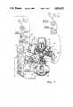
- FIG. 1is a pictorial representation, with parts broken away and parts isolated, of the Valve Operator Remote Monitoring System in accordance with the present invention, shown outfitted in the calibration mode.
- FIG. 2is a pictorical representation of the Valve Operator Remote Monitoring System of FIG. 1, shown in the valve-in-use monitoring mode.
- FIG. 3is a pictorial representation, with parts broken away and parts isolated, of the Valve Operator Remote Monitoring System in accordance with the present invention, shown outfitted in the calibration mode, and showing an alternate embodiment to that of FIG. 1.
- FIG. 1shows the Valve Operator Remote Monitoring System 10 of the present invention outfitted for its calibration mode.
- a valve operator 16of a type typically used in the art, is shown as having a motor 18 which drives a worm shaft 19, which in turn drives a worm 20, which in turn drives a worm gear 22.
- the worm gear 21is formed with a drive sleeve 22 into which is inserted and to which is splined a drive nut (not seen).
- the internally threaded drive nutdrives an externally threaded valve stem 24.
- the valve stem 24engages valve shaft 27 to open or close the valve element 26 of the valve assembly 25.
- a torque switch assembly 32is seen as connected by a post 33 to a spur gear 34 for movement in relation to the worm 20.
- the torque switch assembly 32is of a type typical in the industry and generally includes a switch chamber 35 which houses an electrical/mechanical torque switch (not seen), a face plate 36 and switch setting screws 37 at the face plate.
- the valve assembly 25which is preferably operated on by the system of the present invention is a gate valve of the type typically known in the industry.
- Gate valve assembly 25includes a gate element 26 which is moved up and down perpendicular to the fluid flow through the piping 28.
- the present inventionincludes a dynamic load simulator 40 mounted to the valve operator 16 above the valve stem 24.
- the dynamic load simulator 40comprises a plate member 42 rigidly supported above the operator body 16 by threaded posts 43 which are threaded into existing screw holes of the operator.
- Mounted above the plate member 42is an hydraulic cylinder 45.
- the cylinder piston rod 47protrudes through a central opening in the plate number 42 and extends below the plate member.
- a tubing network 48communicates among the upper and lower sectors of the cylinder 45 and an accumulator 52. Within the tubing network is provided a hand operated flow adjusting valve 50 and a flow directing valve 51.
- the apparatus of the present inventionfurther comprises a load measuring device 54.
- the load measuring device 54is shown as being in the form of the spring pack movement measuring device 54 as disclosed in the Charbonneau 649 Patent.
- U.S. Pat. No. 4,542,649is, by this reference, made a part hereof, and operation of this spring pack movement measuring device is as described therein.
- the spring pack movement measuring device 54determines thrust load values by relating actually measured spring pack movement to the thrust load.
- the output signal of the load measuring device 54is directed by signal cable 58 to a signal conditioner 59 and then to a display Device 60.
- the signal conditioner 59provides a conditioned power supply for the LVDT of the load measuring device 54 and provides necessary sub-components for generating and delivering the output signal to a display device 60, such as an oscilloscope, meter or other such device 60.
- a power terminal assembly 70Shown housed within the control box 39 of the operator 16 is a power terminal assembly 70.
- 3-phase powertypically 480 volts, is directed from an AC power source by power cables 71, 72, 81 to the 3-phase power terminals 73. From the 3-phase power terminals, the power is directed to the motor 18 through the motor cable 74.
- the forestated power connectionsare accomplished in a manner typically known in the industry.
- the three power cables 71, 72, 81are seen as eminating from master control terminals 89 located within the master control center 90 of the power plant.
- a power parameter transducer 75is shown with input leads 76 connecting (i.e. by simple allegator clips) to each of the 3-phase master control terminals 89.
- the power parameter transducer 75is also seen as connected by leads 78 to a current transducer 79.
- the current transducer 79is clamped around one power cable 81 at the master control center 90.
- the power parameter transducer 75is either a power transducer or a Power Factor transducer, depending upon the parameter selected, and is connected in a manner typically known.
- the load measuring device 54comprises a load cell 54' mounted to the lower end of the piston rod 47. Resting on top of the valve stem 24, in communication between the valve stem 24 and the lower surface of the load cell 54 is a valve stem extension 56.
- the load cell 54'is connected by signal conducting cable 58 to the signal conditioner 59.
- the purpose of the signal conditioner 59is to provide a conditioned power supply for the load cell 54; and to provide necessary sub-components for generating and delivering the output signal to the display device 60.
- the power parameter transducer 75is shown with leads 76 connecting (i.e. by simple allegator clips) to each of the three-phase power terminals 73 at the operator control box 39.
- the power parameter transducer 75is also seen as connected by lead 78 to a current transducer 79.
- the current transducer 79is clamped to one input cable 81.
- a separate current transducer 79is clamped to each of the three input cables 71, 72, 81.
- the power parameter transducer 75is connected at its output to a signal conditioner 83 which is connected to a display device 84.
- the Valve Operator Remote Monitoring System 10 of the present inventioncan be utilized to monitor a valve operator 16 from a remote control center (i.e. master control center 90).
- the method of the present inventionwill assist the user in recognizing that a valve operator positioned in a remote location is jammed, over packed, damaged or otherwise malfunctioning.
- the determination of a valve malfunction in accordance with the present inventionis determined as a condition in which the valve thrust available to the valve operator has reached an unacceptable low level. This unacceptable low level of available thrust is, for purposes of the present invention, defined as the "minimum thrust" which the user deems necessary for the valve operator 16 to properly open and close the valve 26.
- This minimum thrust valueis typically calculated or otherwise determined by an engineer, power plant administrator, the user or other competent party.
- One method of determining the minimum thrustis to calculate the thrust required to overcome the maximum ⁇ P (pressure differential) of the valve and then increase that thrust by a margin of safety (i.e. 25%), using the resulting figure as the "minimum thrust".
- the method of the present inventionis generally performed as follows:
- the userassures that the torque switch 32 setting of the operator 16 which is to be monitored is properly set. It is the purpose of the torque switch setting to automatically cut off the motor 18 when the valve operator torque (and, thus, thrust load) has exceeded a predetermined maximum.
- the setting and verification of the torque switch settingare accomplished, preferably, in accordance with the methods of the Charbonneau 649 Patent.
- the valve operatoris outfitted with the system apparatus of the present invention in the manner described above in relation to FIG. 1 (and FIG. 3). With the system apparatus 10 outfitted as per FIGS. 1 and 3, the system is in the calibration mode. Calibration of the remote monitoring system 10 of the present invention is accomplished as follows:
- valve operator motor 18is turned on and the operator is set to open the valve gate 26. With the operator in this open-valve mode, the driven valve stem 24 begins to move upward pushing against the valve stem extension 56 of the dynamic load simulator 40. Upward movement of the valve stem extension 56 compresses the piston rod 47 into the hydraulic cylinder 45.
- the usersimulates a load on the value stem 24.
- the simulated loadsimulates a blockage, warpage, excessive packing load, or other stressful condition of the valve operator.
- the load which the user will simulateis preferrably a load which will deplete the available operator thrust to a level which is equal to the "minimum Thrust" deemed necessary for proper opening and closing of the valve, as determined at step 2 above.
- the maximum available thrustis that maximum thrust which the operator 16 can deliver before the torque switch 32 is tripped; the minimum required thrust is that determined at step 2 above; and, thus, the simulated load to be created by the dynamic load simulator 40 would be equal to: the maximum available thrust minus the minimum required thrust.
- the simulated loadis measured at the load measuring device 54.
- measurement of the simulated loadis accomplished through the use of a spring pack movement device 54 which operates in a manner described in the Charbonneau's 649 Patent; the specification of that patent having been incorporated herein by reference.
- the signal created by the LVDT of the spring pack movement measuring device 54is conveyed to the signal conditioner 59 and subsequently delivered to the device 60 for display in the form of a meter reading, load/time trace or other user observable format. By observation of the display device 60 signal, the user verifies that the simulated load has reached the desired value.
- measurement of the simulated loadis by the load cell 54'.
- the force signal generated at the load cell by force of the valve stem extension 56 and piston rod 47is conveyed to the signal conditioner 59.
- the output signalis read by the user at the display device 60 in the form of a meter reading or a generated curve such as a load/time curve. By observation of the display device signal, the user verifies that the simulated load has reached the desired value.
- the simulated loadis sustained for a sufficient time to stabilize the motor parameters at the given operator load.
- the power parameter transducer 75is connected (or was previously connected) to the master control terminals 89 and to the current transducer 79 in the master control center 90, as previously described.
- the userconnects the power parameter transducer 75 so as to generate from the power parameter transducer an output as to either the motor power or the motor power factor. Either of these parameters may be monitored by the user within the scope of the present invention. Both of these power parameters vary directly with the stem load (and simulated load).
- the output of the power parameter transducer 75is provided through the signal conditioner 83 and display device 84 in the form of a meter reading, power parameter/time curve or other user observable manner. It is within the scope of the present invention to provide a power parameter versus thrust load curve by inputting the respective output from the load measuring device 54, and the power parameter transducer 75 to the same, appropriately receptive signal conditioner and recording device.
- control value for the power parametercorresponds with the maximum thrust load which the user will tolerate to build up within the valve operator 16 prior to the time that the valve gate 26 has fully opened or fully closed.
- the valve operator 16is returned to service by removal of the dynamic load simulator 40, load cell 54 and/or spring pack movement monitoring device 54.
- the system apparatus 10 of the present inventionis now no longer in the calibration mode (see FIG. 1 and 3) but is now in the monitoring mode (see FIG. 2).
- the power parameter transducer 75remains connected, preferrably in its non-intrusive manner as discussed above, to the power terminals 89 or 73.
- the output from the power parameter transducer 75is conveyed by appropriate signal conveying cable to its signal conditioner 83 and then to the display device 84, i.e. meter or oscilloscope.
- the usermonitors the power parameter (motor power and/or motor power factor) on a periodic basis at the master control center 90 or, in certain embodiments, at the valve operator 16.
- the usermay be alerted, either by mental association or by a physical alarm that there is a possibility that the thrust now available to the operator is insufficient to successfully open or close the valve gate 26.
- the usershould know to investigate the valve to determine if there is, indeed, a condition which requires repair, maintenance or replacement of the valve.
- a physical alarmis not a required component of the present invention, alternate embodiments of the invention include a buzzer alarm or other audible signal.
- the recording device located at the remote master control centeris a device which provides a printed, time related record of the monitored parameter to allow for scanning by the user of the parameter condition over a period of time.
- the power parameter measurements, during both the calibration mode (control value) and the valve-in-use monitoring mode (actual value)are taken from the same terminal block.
- that terminal blockis preferrably the master control terminal 89.
- the common terminal blockis the operator terminal 73.
- control value determined during the calibration modeis taken at the valve power terminal assembly 70 (see FIG. 3), while the actual values measured during the valve-in-use monitoring mode are still taken at the remote control center terminal 89.
- the present inventionis described with particular reference to AC Powered valve operators, it is within the scope of the invention to monitor DC powered valve operators.
- the monitored power parameteris motor power only.
Landscapes
- Engineering & Computer Science (AREA)
- General Engineering & Computer Science (AREA)
- Mechanical Engineering (AREA)
- Testing Of Devices, Machine Parts, Or Other Structures Thereof (AREA)
Abstract
Description
Claims (17)
Priority Applications (4)
| Application Number | Priority Date | Filing Date | Title |
|---|---|---|---|
| US06/848,451US4831873A (en) | 1986-04-04 | 1986-04-04 | Method and apparatus for remote monitoring of valves and valve operators |
| US07/092,648US4869102A (en) | 1986-04-04 | 1987-09-03 | Method and apparatus for remote monitoring of valves and valve operators |
| US07/278,977US4891975A (en) | 1986-04-04 | 1988-12-01 | Method and apparatus for remote monitoring of valves and valve operators |
| US07/446,985US5000040A (en) | 1986-04-04 | 1989-12-06 | Method and apparatus for remote monitoring of valves and valve operators |
Applications Claiming Priority (1)
| Application Number | Priority Date | Filing Date | Title |
|---|---|---|---|
| US06/848,451US4831873A (en) | 1986-04-04 | 1986-04-04 | Method and apparatus for remote monitoring of valves and valve operators |
Related Child Applications (2)
| Application Number | Title | Priority Date | Filing Date |
|---|---|---|---|
| US07/092,648Continuation-In-PartUS4869102A (en) | 1986-04-04 | 1987-09-03 | Method and apparatus for remote monitoring of valves and valve operators |
| US07/278,977ContinuationUS4891975A (en) | 1986-04-04 | 1988-12-01 | Method and apparatus for remote monitoring of valves and valve operators |
Publications (1)
| Publication Number | Publication Date |
|---|---|
| US4831873Atrue US4831873A (en) | 1989-05-23 |
Family
ID=25303310
Family Applications (1)
| Application Number | Title | Priority Date | Filing Date |
|---|---|---|---|
| US06/848,451Expired - Fee RelatedUS4831873A (en) | 1986-04-04 | 1986-04-04 | Method and apparatus for remote monitoring of valves and valve operators |
Country Status (1)
| Country | Link |
|---|---|
| US (1) | US4831873A (en) |
Cited By (32)
| Publication number | Priority date | Publication date | Assignee | Title |
|---|---|---|---|---|
| US5000040A (en)* | 1986-04-04 | 1991-03-19 | Movats Incorporated | Method and apparatus for remote monitoring of valves and valve operators |
| US5029597A (en)* | 1990-01-22 | 1991-07-09 | Liberty Technology Center, Inc. | Controller for controlling the operation of a motor operated valve combination |
| US5056046A (en)* | 1989-06-20 | 1991-10-08 | Combustion Engineering, Inc. | Pneumatic operated valve data acquisitioner |
| US5168753A (en)* | 1990-12-20 | 1992-12-08 | Krupp Maschinentechnik Gesellschaft Mit Beschrankter Haftung | Measuring device for detecting parameters charterizing the operating behavior of hydraulic assembles |
| US5174152A (en)* | 1991-03-06 | 1992-12-29 | Wohld Peter R | Power operated valve stem thrust verification test system |
| WO1993005378A1 (en)* | 1991-09-03 | 1993-03-18 | Westinghouse Electric Corporation | Method of monitoring the condition of a motor operated valve system |
| US5239874A (en)* | 1990-06-19 | 1993-08-31 | Westinghouse Electric Corp. | Method of monitoring the condition of a motor operated valve system |
| WO1993019317A1 (en)* | 1992-03-18 | 1993-09-30 | Elektro-Mechanik Gmbh | Process and device for testing the operability of a valve or fitting driven a motor element |
| US5257535A (en)* | 1992-09-16 | 1993-11-02 | Westinghouse Electric Corp. | Stem stress measuring instrument for valve operating system |
| US5430368A (en)* | 1993-06-03 | 1995-07-04 | Liberty Technologies, Inc. | Method for remotely approximating the stem thrust of motor operated valves |
| US5432436A (en)* | 1993-06-03 | 1995-07-11 | Liberty Technologies, Inc. | Method for remotely approximating the stem thurst of motor operated valves |
| US5453626A (en)* | 1994-06-28 | 1995-09-26 | Dispigna; Angelo V. | Valve stem thrust measurement system |
| US5524484A (en)* | 1993-12-22 | 1996-06-11 | Westinghouse Electric Corporation | Solenoid operated valve diagnostic system |
| US5533410A (en)* | 1993-12-03 | 1996-07-09 | Westinghouse Electric Corporation | Motor power measuring cell for motor operated valves |
| US5548997A (en)* | 1991-09-03 | 1996-08-27 | Westinghouse Electric Corporation | Apparatus for applying a known axial force to a valve stem |
| WO1996030684A1 (en)* | 1995-03-31 | 1996-10-03 | Institut Für Sicherheitstechnologie (Istec) Gmbh | Process for monitoring and operating valve units, in particular motor-driven valve units |
| US5651667A (en)* | 1991-10-11 | 1997-07-29 | Helix Technology Corporation | Cryopump synchronous motor load monitor |
| US5673331A (en)* | 1995-06-03 | 1997-09-30 | United States Department Of Energy | Method and apparatus for reading meters from a video image |
| US5966679A (en)* | 1995-10-30 | 1999-10-12 | Fisher Controls International, Inc. | Method of and apparatus for nonobtrusively obtaining on-line measurements of a process control device parameter |
| US5992229A (en)* | 1996-02-05 | 1999-11-30 | Neles-Jamesbury Oy | Method and equipment for determining the performance of control valve |
| US6192321B1 (en) | 1997-09-29 | 2001-02-20 | Fisher Controls International, Inc. | Method of and apparatus for deterministically obtaining measurements |
| US20020040284A1 (en)* | 1997-09-29 | 2002-04-04 | Junk Kenneth W. | Detection and discrimination of instabilities in process control loops |
| US6466893B1 (en) | 1997-09-29 | 2002-10-15 | Fisher Controls International, Inc. | Statistical determination of estimates of process control loop parameters |
| US20040228173A1 (en)* | 2003-02-14 | 2004-11-18 | Larry Schoonover | Method, system and storage medium for performing online valve diagnostics |
| US20070142936A1 (en)* | 2005-10-04 | 2007-06-21 | Fisher-Rosemount Systems, Inc. | Analytical Server Integrated in a Process Control Network |
| US7283894B2 (en) | 2006-02-10 | 2007-10-16 | Dresser, Inc. | System and method for fluid regulation |
| US20080163936A1 (en)* | 2007-01-05 | 2008-07-10 | Dresser, Inc. | Control Valve and Positioner Diagnostics |
| US7444191B2 (en) | 2005-10-04 | 2008-10-28 | Fisher-Rosemount Systems, Inc. | Process model identification in a process control system |
| US20080309507A1 (en)* | 2007-06-12 | 2008-12-18 | Paul Gene Anderson | Self-configuring data acquisition system for diagnostic testing |
| US8036760B2 (en) | 2005-10-04 | 2011-10-11 | Fisher-Rosemount Systems, Inc. | Method and apparatus for intelligent control and monitoring in a process control system |
| US20120016607A1 (en)* | 2007-06-15 | 2012-01-19 | Michael Edward Cottrell | Remote monitoring systems and methods |
| US20170232285A1 (en)* | 2014-09-16 | 2017-08-17 | Amtron Valve Monitoring Device Pty. Ltd. | Valve monitoring |
Citations (8)
| Publication number | Priority date | Publication date | Assignee | Title |
|---|---|---|---|---|
| SU431464A1 (en)* | 1970-03-03 | 1974-06-05 | ||
| US4029122A (en)* | 1976-03-11 | 1977-06-14 | Westinghouse Electric Corporation | Apparatus and method for determining friction forces in position modulated valves |
| US4123009A (en)* | 1974-05-14 | 1978-10-31 | The International Nickel Company, Inc. | Load sensor for a grinding mill |
| US4321529A (en)* | 1979-10-02 | 1982-03-23 | Simmonds Charles W | Power factor metering device |
| US4333118A (en)* | 1980-01-29 | 1982-06-01 | El-Fi Innovationer Ab | Load indicators for alternating-current motors |
| US4542649A (en)* | 1983-07-19 | 1985-09-24 | Charbonneau And Godfrey Associates | Motor operated valve analysis and testing system |
| US4551808A (en)* | 1983-03-30 | 1985-11-05 | Eaton Corporation | Tool wear sensors |
| US4570903A (en)* | 1982-04-19 | 1986-02-18 | Crass Otto G | Method and apparatus for measurement of valve stem thrust |
- 1986
- 1986-04-04USUS06/848,451patent/US4831873A/ennot_activeExpired - Fee Related
Patent Citations (8)
| Publication number | Priority date | Publication date | Assignee | Title |
|---|---|---|---|---|
| SU431464A1 (en)* | 1970-03-03 | 1974-06-05 | ||
| US4123009A (en)* | 1974-05-14 | 1978-10-31 | The International Nickel Company, Inc. | Load sensor for a grinding mill |
| US4029122A (en)* | 1976-03-11 | 1977-06-14 | Westinghouse Electric Corporation | Apparatus and method for determining friction forces in position modulated valves |
| US4321529A (en)* | 1979-10-02 | 1982-03-23 | Simmonds Charles W | Power factor metering device |
| US4333118A (en)* | 1980-01-29 | 1982-06-01 | El-Fi Innovationer Ab | Load indicators for alternating-current motors |
| US4570903A (en)* | 1982-04-19 | 1986-02-18 | Crass Otto G | Method and apparatus for measurement of valve stem thrust |
| US4551808A (en)* | 1983-03-30 | 1985-11-05 | Eaton Corporation | Tool wear sensors |
| US4542649A (en)* | 1983-07-19 | 1985-09-24 | Charbonneau And Godfrey Associates | Motor operated valve analysis and testing system |
Non-Patent Citations (6)
| Title |
|---|
| Square D Class 8430 Type G Load Converter Relays Instruction Sheet 63080 003 01, Nov., 1983.* |
| Square D Product Data Bulletin M 629 Load Monitoring For Three Phase Induction Motors Apr., 1984.* |
| Square D Product News Control Products Load Detector and Load Converter Relays Type V and G IC 277, Class 8430, Nov. 1983.* |
| Square D-Class 8430 Type G Load Converter Relays-Instruction Sheet 63080-003-01, Nov., 1983. |
| Square D-Product Data-Bulletin M-629 Load Monitoring For Three Phase Induction Motors-Apr., 1984. |
| Square D-Product News-Control Products-Load Detector and Load Converter Relays Type V and G-IC-277, Class 8430, Nov. 1983. |
Cited By (50)
| Publication number | Priority date | Publication date | Assignee | Title |
|---|---|---|---|---|
| US5000040A (en)* | 1986-04-04 | 1991-03-19 | Movats Incorporated | Method and apparatus for remote monitoring of valves and valve operators |
| US5056046A (en)* | 1989-06-20 | 1991-10-08 | Combustion Engineering, Inc. | Pneumatic operated valve data acquisitioner |
| US5029597A (en)* | 1990-01-22 | 1991-07-09 | Liberty Technology Center, Inc. | Controller for controlling the operation of a motor operated valve combination |
| US5239874A (en)* | 1990-06-19 | 1993-08-31 | Westinghouse Electric Corp. | Method of monitoring the condition of a motor operated valve system |
| US5168753A (en)* | 1990-12-20 | 1992-12-08 | Krupp Maschinentechnik Gesellschaft Mit Beschrankter Haftung | Measuring device for detecting parameters charterizing the operating behavior of hydraulic assembles |
| US5174152A (en)* | 1991-03-06 | 1992-12-29 | Wohld Peter R | Power operated valve stem thrust verification test system |
| US5548997A (en)* | 1991-09-03 | 1996-08-27 | Westinghouse Electric Corporation | Apparatus for applying a known axial force to a valve stem |
| JP3188267B2 (en) | 1991-09-03 | 2001-07-16 | ウエスチングハウス・エレクトリック・コーポレイション | Method of monitoring the condition of a motor-driven valve system |
| WO1993005378A1 (en)* | 1991-09-03 | 1993-03-18 | Westinghouse Electric Corporation | Method of monitoring the condition of a motor operated valve system |
| US5900822A (en)* | 1991-10-11 | 1999-05-04 | Helix Technology Corporation | Cryopump synchronous motor load monitor |
| US5651667A (en)* | 1991-10-11 | 1997-07-29 | Helix Technology Corporation | Cryopump synchronous motor load monitor |
| WO1993019317A1 (en)* | 1992-03-18 | 1993-09-30 | Elektro-Mechanik Gmbh | Process and device for testing the operability of a valve or fitting driven a motor element |
| US5257535A (en)* | 1992-09-16 | 1993-11-02 | Westinghouse Electric Corp. | Stem stress measuring instrument for valve operating system |
| US5475299A (en)* | 1993-06-03 | 1995-12-12 | Liberty Technologies, Inc. | Method for remotely determining operability of motor operated valves |
| US5432436A (en)* | 1993-06-03 | 1995-07-11 | Liberty Technologies, Inc. | Method for remotely approximating the stem thurst of motor operated valves |
| US5430368A (en)* | 1993-06-03 | 1995-07-04 | Liberty Technologies, Inc. | Method for remotely approximating the stem thrust of motor operated valves |
| US5533410A (en)* | 1993-12-03 | 1996-07-09 | Westinghouse Electric Corporation | Motor power measuring cell for motor operated valves |
| US5524484A (en)* | 1993-12-22 | 1996-06-11 | Westinghouse Electric Corporation | Solenoid operated valve diagnostic system |
| US5453626A (en)* | 1994-06-28 | 1995-09-26 | Dispigna; Angelo V. | Valve stem thrust measurement system |
| WO1996030684A1 (en)* | 1995-03-31 | 1996-10-03 | Institut Für Sicherheitstechnologie (Istec) Gmbh | Process for monitoring and operating valve units, in particular motor-driven valve units |
| US5673331A (en)* | 1995-06-03 | 1997-09-30 | United States Department Of Energy | Method and apparatus for reading meters from a video image |
| US5966679A (en)* | 1995-10-30 | 1999-10-12 | Fisher Controls International, Inc. | Method of and apparatus for nonobtrusively obtaining on-line measurements of a process control device parameter |
| US5992229A (en)* | 1996-02-05 | 1999-11-30 | Neles-Jamesbury Oy | Method and equipment for determining the performance of control valve |
| US20020040284A1 (en)* | 1997-09-29 | 2002-04-04 | Junk Kenneth W. | Detection and discrimination of instabilities in process control loops |
| US6192321B1 (en) | 1997-09-29 | 2001-02-20 | Fisher Controls International, Inc. | Method of and apparatus for deterministically obtaining measurements |
| US6466893B1 (en) | 1997-09-29 | 2002-10-15 | Fisher Controls International, Inc. | Statistical determination of estimates of process control loop parameters |
| US6804618B2 (en) | 1997-09-29 | 2004-10-12 | Fisher Controls International, Llc | Detection and discrimination of instabilities in process control loops |
| US20050021298A1 (en)* | 1997-09-29 | 2005-01-27 | Fisher Controls International Llc | Detection and discrimination of instabilities in process control loops |
| US7039537B2 (en) | 1997-09-29 | 2006-05-02 | Fisher Controls Llc. | Detection and discrimination of instabilities in process control loops |
| US20040228173A1 (en)* | 2003-02-14 | 2004-11-18 | Larry Schoonover | Method, system and storage medium for performing online valve diagnostics |
| US7089086B2 (en) | 2003-02-14 | 2006-08-08 | Dresser, Inc. | Method, system and storage medium for performing online valve diagnostics |
| US8046096B2 (en) | 2005-10-04 | 2011-10-25 | Fisher-Rosemount Systems, Inc. | Analytical server integrated in a process control network |
| US8036760B2 (en) | 2005-10-04 | 2011-10-11 | Fisher-Rosemount Systems, Inc. | Method and apparatus for intelligent control and monitoring in a process control system |
| US11487252B2 (en) | 2005-10-04 | 2022-11-01 | Fisher-Rosemount Systems, Inc. | Process model identification in a process control system |
| US7444191B2 (en) | 2005-10-04 | 2008-10-28 | Fisher-Rosemount Systems, Inc. | Process model identification in a process control system |
| US10310456B2 (en) | 2005-10-04 | 2019-06-04 | Fisher-Rosemount Systems, Inc. | Process model identification in a process control system |
| US8706267B2 (en) | 2005-10-04 | 2014-04-22 | Fisher-Rosemount Systems, Inc. | Process model identification in a process control system |
| US20070142936A1 (en)* | 2005-10-04 | 2007-06-21 | Fisher-Rosemount Systems, Inc. | Analytical Server Integrated in a Process Control Network |
| US7738975B2 (en) | 2005-10-04 | 2010-06-15 | Fisher-Rosemount Systems, Inc. | Analytical server integrated in a process control network |
| US20100228363A1 (en)* | 2005-10-04 | 2010-09-09 | Fisher-Rosemount Systems, Inc. | Analytical server integrated in a process control network |
| US7283894B2 (en) | 2006-02-10 | 2007-10-16 | Dresser, Inc. | System and method for fluid regulation |
| US7890216B2 (en) | 2007-01-05 | 2011-02-15 | Dresser, Inc. | Control valve and positioner diagnostics |
| US20090216350A1 (en)* | 2007-01-05 | 2009-08-27 | Dresser, Inc. | Control valve and positioner diagnostics |
| US7539560B2 (en) | 2007-01-05 | 2009-05-26 | Dresser, Inc. | Control valve and positioner diagnostics |
| US20080163936A1 (en)* | 2007-01-05 | 2008-07-10 | Dresser, Inc. | Control Valve and Positioner Diagnostics |
| US20080309507A1 (en)* | 2007-06-12 | 2008-12-18 | Paul Gene Anderson | Self-configuring data acquisition system for diagnostic testing |
| US20120016607A1 (en)* | 2007-06-15 | 2012-01-19 | Michael Edward Cottrell | Remote monitoring systems and methods |
| US8688405B2 (en)* | 2007-06-15 | 2014-04-01 | Shell Oil Company | Remote monitoring systems and methods |
| US20170232285A1 (en)* | 2014-09-16 | 2017-08-17 | Amtron Valve Monitoring Device Pty. Ltd. | Valve monitoring |
| US10188886B2 (en)* | 2014-09-16 | 2019-01-29 | Amtron Valve Monitoring Device Pty. Ltd. | Valve monitoring |
Similar Documents
| Publication | Publication Date | Title |
|---|---|---|
| US4831873A (en) | Method and apparatus for remote monitoring of valves and valve operators | |
| US5000040A (en) | Method and apparatus for remote monitoring of valves and valve operators | |
| US4891975A (en) | Method and apparatus for remote monitoring of valves and valve operators | |
| US4869102A (en) | Method and apparatus for remote monitoring of valves and valve operators | |
| US4690003A (en) | Motor operated valve analysis and testing system | |
| US4542649A (en) | Motor operated valve analysis and testing system | |
| US4570903A (en) | Method and apparatus for measurement of valve stem thrust | |
| US4693113A (en) | Motor operated valve analysis and testing system | |
| US4888996A (en) | DC motor operated valve remote monitoring system | |
| US4896101A (en) | Method for monitoring, recording, and evaluating valve operating trends | |
| DE68911617T2 (en) | METHOD AND DEVICE FOR MEASURING AND WARNING ABOUT DYNAMIC LOADS IN SHOCK-INDUCING SYSTEMS. | |
| US4805451A (en) | System for evaluating the condition and performance of a valve and valve operator combination | |
| US5239874A (en) | Method of monitoring the condition of a motor operated valve system | |
| JP3192429B2 (en) | Apparatus and method used for testing gas decompression apparatus | |
| US5197338A (en) | System and method for determining torque output of motor actuated valve operators | |
| EP0252143A4 (en) | Motor operated valve analysis and testing system with monitoring of spring pack movement through torque switch post | |
| KR20090019421A (en) | Valve performance test apparatus and method | |
| CN106093776A (en) | A kind of simulated machine load characteristic low voltage test system based on converter | |
| US4860596A (en) | Motor operated valve analysis and testing system with monitoring of spring pack movement through torque switch post | |
| EP1676027A1 (en) | Method of testing a fuel injection valve for a diesel engine | |
| CN103196664B (en) | Hydraulic power plant mechanical hydraulic pressure over-speed protection device simulation test platform and test method | |
| US5548997A (en) | Apparatus for applying a known axial force to a valve stem | |
| CN110333067B (en) | Stop valve checking device and checking method | |
| CN112857790A (en) | Pressure relief valve high-low temperature opening performance calibration device and calibration method | |
| CN206175386U (en) | Hydraulic system fault simulation and dismouting test bench |
Legal Events
| Date | Code | Title | Description |
|---|---|---|---|
| AS | Assignment | Owner name:MOVATS INCORPORATED, 2999 JOHNSON FERRY ROAD, , MA Free format text:ASSIGNMENT OF ASSIGNORS INTEREST.;ASSIGNOR:SAYED, EDMOND A.;REEL/FRAME:004558/0937 Owner name:MOVATS INCORPORATED, 2999 JOHNSON FERRY ROAD, MARI Free format text:ASSIGNMENT OF ASSIGNORS INTEREST.;ASSIGNOR:CHARBONNEAU, ARTHUR G.;REEL/FRAME:004558/0939 Effective date:19860501 Owner name:MOVATS INCORPORATED, 2999 JOHNSON FERRY ROAD, MARI Free format text:ASSIGNMENT OF ASSIGNORS INTEREST.;ASSIGNOR:HALE, STANLEY N.;REEL/FRAME:004558/0946 Effective date:19860501 Owner name:MOVATS INCORPORATED,GEORGIA Free format text:ASSIGNMENT OF ASSIGNORS INTEREST;ASSIGNOR:CHARBONNEAU, ARTHUR G.;REEL/FRAME:004558/0939 Effective date:19860501 Owner name:MOVATS INCORPORATED,GEORGIA Free format text:ASSIGNMENT OF ASSIGNORS INTEREST;ASSIGNOR:HALE, STANLEY N.;REEL/FRAME:004558/0946 Effective date:19860501 | |
| AS | Assignment | Owner name:WESTINGHOUSE ELECTRIC CORPORATION, WESTINGHOUSE BU Free format text:ASSIGNMENT OF ASSIGNORS INTEREST.;ASSIGNOR:NUCLEAR SUPPORT SERVICES, INC.;REEL/FRAME:005634/0916 Effective date:19910313 | |
| FEPP | Fee payment procedure | Free format text:PAYOR NUMBER ASSIGNED (ORIGINAL EVENT CODE: ASPN); ENTITY STATUS OF PATENT OWNER: LARGE ENTITY | |
| FPAY | Fee payment | Year of fee payment:4 | |
| REMI | Maintenance fee reminder mailed | ||
| LAPS | Lapse for failure to pay maintenance fees | ||
| FP | Lapsed due to failure to pay maintenance fee | Effective date:20010523 | |
| STCH | Information on status: patent discontinuation | Free format text:PATENT EXPIRED DUE TO NONPAYMENT OF MAINTENANCE FEES UNDER 37 CFR 1.362 |