US4830430A - Split-back chair, particularly office chair - Google Patents
Split-back chair, particularly office chairDownload PDFInfo
- Publication number
- US4830430A US4830430AUS07/149,106US14910688AUS4830430AUS 4830430 AUS4830430 AUS 4830430AUS 14910688 AUS14910688 AUS 14910688AUS 4830430 AUS4830430 AUS 4830430A
- Authority
- US
- United States
- Prior art keywords
- spring
- chair
- attachment
- elements
- parts
- Prior art date
- Legal status (The legal status is an assumption and is not a legal conclusion. Google has not performed a legal analysis and makes no representation as to the accuracy of the status listed.)
- Expired - Fee Related
Links
- 230000008878couplingEffects0.000claimsdescription6
- 238000010168coupling processMethods0.000claimsdescription6
- 238000005859coupling reactionMethods0.000claimsdescription6
- 230000008859changeEffects0.000claimsdescription5
- 230000001154acute effectEffects0.000claimsdescription4
- 230000008901benefitEffects0.000description7
- 238000010276constructionMethods0.000description5
- 239000000463materialSubstances0.000description4
- 230000000717retained effectEffects0.000description4
- 230000009977dual effectEffects0.000description3
- 230000007246mechanismEffects0.000description3
- 229910000639Spring steelInorganic materials0.000description2
- 230000000694effectsEffects0.000description2
- 238000004519manufacturing processMethods0.000description2
- 239000002184metalSubstances0.000description2
- 230000035807sensationEffects0.000description2
- 241000239290AraneaeSpecies0.000description1
- 238000005452bendingMethods0.000description1
- 230000037237body shapeEffects0.000description1
- 210000000078clawAnatomy0.000description1
- 230000003247decreasing effectEffects0.000description1
- 230000001771impaired effectEffects0.000description1
- 238000003780insertionMethods0.000description1
- 230000037431insertionEffects0.000description1
- 230000004048modificationEffects0.000description1
- 238000012986modificationMethods0.000description1
- 238000010137moulding (plastic)Methods0.000description1
- 230000001360synchronised effectEffects0.000description1
Images


Classifications
- A—HUMAN NECESSITIES
- A47—FURNITURE; DOMESTIC ARTICLES OR APPLIANCES; COFFEE MILLS; SPICE MILLS; SUCTION CLEANERS IN GENERAL
- A47C—CHAIRS; SOFAS; BEDS
- A47C7/00—Parts, details, or accessories of chairs or stools
- A47C7/36—Supports for the head or the back
- A47C7/40—Supports for the head or the back for the back
- A47C7/44—Supports for the head or the back for the back with elastically-mounted back-rest or backrest-seat unit in the base frame
- A47C7/445—Supports for the head or the back for the back with elastically-mounted back-rest or backrest-seat unit in the base frame with bar or leaf springs
Definitions
- the present inventionrelates to chairs, and more particularly to the construction of a multi-part back for a chair, especially for an office chair, in which the back and the seat both can tilt.
- torsion rods or barsextend from one side of the back to the other, and are retained, rotatably, in the center of the back.
- the ends of the torsion rods or barshave oppositely bent-over parts secured thereto, for attachment to the respective back segments.
- five attachment elements or arrangementsare necessary, four for the ends of the torsion rods and one for the center, an expensive and complex arrangement.
- Adjustment of the spring pressureis not possible in these arrangements. Thus, the designer is faced with always designing for a compromise. If the user is light-weight, the back is too stiff. If the user is quite heavy, it is too flexible, and does not provide the necessary support; on the contrary, it may lead the user to have a feeling of instability. For a heavy user, the segmented back is less desirable than a single unit back; for a light person, the segmented back is useless and merely excessively complex and expensive.
- two segments of a back--theremay be more--are respectively interconnected by spring elements which couple the back elements together.
- Adjustable clamps or claws or the likeare associated with the spring elements to change the spring force--deflection characteristics of the spring elements connecting the back segments together.
- the spring elementsare essentially vertically extending rods, secured firmly to one of the back elements but slidably or adjustably secured to the other, to which clamping elements may be attached in such a way that the spring force--deflection characteristics of the coupling of the back segments can be changed.
- two such rod sectionsare located at respectively opposite sides of the center line or a plane of symmetry of the back.
- the rod elementsthemselves can be dual elements, for example U-shaped springs, in which end portions of the legs of the springs are, respectively, rigidly secured to one of the segments and adjustably to the other, for example by placing an adjustable clamping bar across the U-shaped spring elements at a position in the vicinity of the bend of the U or, alternatively, by providing an adjustable back-up element which itself can be stiff or slightly springy with, however, a substantially stiffer spring constant than the U elements.
- Constructing the spring element in the form of U-shaped dual spring elementshas the additional advantage that the spring elements can be located already on a pre-bowed or cradling-type frame, that is, the planes of the U can extend at an acute angle with respect to the sagittal plane of the chair, or of the user, respectively.
- specific use of different connections for the respective sides of the chairis not necessary; nor is it required that the spring elements be located in the same plane. The designer thus has wide latitude.
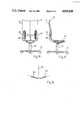
- FIG. 1is a rear elevational view of the chair
- FIG. 2is a side elevational view of the chair
- FIG. 3is a horizontal schematic sectional view through the chair, illustrating the placement of U-shaped spring elements in a cradle-type back;
- FIG. 4is a fragmentary enlarged elevation of a first embodiment of the invention, illustrating attachment of a U-spring;
- FIG. 5is a section along line V--V of FIG. 4;
- FIG. 6is a section along line VI--VI of FIG. 4;
- FIG. 7is a rear elevational view of a support for a spring element
- FIG. 8is a rear elevational view for an upper support of a spring element
- FIG. 9is a section along line IX--IX of FIG. 8;
- FIG. 10is a rear elevational view of another embodiment of the invention.
- FIG. 11is a section along line XI--XI of FIG. 10;
- FIG.12is a section along line XII--XII of FIG. 10;
- FIG. 13is a section along line XIII--XIII of FIG. 11;
- FIG. 14is a rear elevational view of the upper attachment of a U-spring
- FIG. 15is a section along the broken section line XV--XV of FIG. 14;
- FIG. 16is a front elevational view in which the spring elements are located at the forward side of the chair back;
- FIG. 17is a side elevational view of the chair of FIG. 16.
- FIG. 18is a schematic horizontal sectional view through the chair back of FIG. 16 or 17, and illustrating placement of the spring.
- a base supportformed as a spider 11, for example with casters, retains a center post 13 on which a seat 15 is secured.
- the seat 15is connected to the back 17.
- Seat 15 and back 17are padded, as usual. In the illustration shown, the padding has been removed so that the adjustment mechanism on the back is clearly visible.
- the chairmay be of the synchronous movement type, in which the back 17 inclines when the seat 15 is inclined, but by only half the angle of inclination as the seat.
- the present inventionis preferably applicable with other types of office chairs, for example where the back moves independently, or is rigidly coupled to the seat. In essence, the presence invention is related to the construction of the back, independently of the remainder of the chair.
- the back 17includes at least two vertically arranged or superposed or stacked segments 19, 21, which are coupled by two spaced spring links 23. More than two segments may be used although, for most applications, two segments are sufficient. It is, of course, also possible to utilize only a single spring element 23 which, then, would be located at the central plane of symmetry shown by the central or sagittal axis 25 (FIG. 3). More than two spring elements or units 23 may be used.
- each one of the spring elements 23are coupled to an arrangement 27 (FIG. 4) which permits independent adjustment by an adjustment element, shown as an adjustment screw 29, to change the spring characteristics of the spring coupling or spring joint.
- an adjustment elementshown as an adjustment screw 29, to change the spring characteristics of the spring coupling or spring joint.
- the spring link unit 23is coupled to a first or lower support 31 (FIGS. 4-6) which, in turn, is coupled to the segment 19 of the chair at the lower side; a second support 33 (FIGS. 8 and 9) is coupled to the upper segment 21 of the back 17 of the chair.
- Each one of the spring links 23includes at least one round spring bar 35, made of springy material, for example spring steel.
- the round bars 35preferably, are bent in U-shaped form to form U-spring elements 37.
- One end of the spring elements 37is secured to the support 31.
- a clamping jaw 38is secured by screws 39 to the support base 31 which, in turn, is screwed by screws passing through screw holes 31a into the back section 19 of the back 17.
- a support 33is secured to the upper segment 21 with a nut 33a.
- the upper end of the spring element 37is clamped to the upper segment 21 by a screw secured to the support 33 and a nut 41, clamping a clamping jaw or bridge 43 to secure the U-spring rods to the upper section 21.
- the spring-deflection characteristic of the spring element 37can be changed, which includes a changing mechanism essentially formed of a slider 45, which can be shifted in a guide track 47 located in the support 31.
- the rods 35 of the spring element 37are engaged by the slider 45 or, alternatively, they are positioned immediately adjacent thereto.
- the effective length of the springwill change, that is, will be less or longer.
- the path over which the slider 45 can be changedis defined and limited by the slit 49 in the support 31.
- the slider 45is coupled to the adjustment element 29 by an engagement spring 53 which can fit in suitable depressions formed in the guide track 47, the engagement spring 53 being undulated so that specific adjustment locations are determined.
- the adjustment element 29can be constructed merely in form of a push button to, respectively, engage the spring element 53 in the corrugations 55; alternatively, a camming rotary movement can be provided for locking the element 29 in position.
- the spring link 23includes a first support 31' and a second, upper support 33'.
- essentially similar elementshave been given the same reference numeral, with prime notation, as appropriate.
- Two round rods 35are bent into U-shape 37.
- One end of the U-spring element 37is secured in support 31' which, for example, is formed as a plastic block 30.
- Screws 32are molded into the block 30 which permit attachment of the support 31' on the segment 19 by nuts 34.
- the upper end of the spring element unit 37is secured by clamp 43' and the support 33' to the seat back section or segment 21.
- the clamp 43has four threaded studs 44 (FIG. 15) which pass through openings or bores 46 of the segment 21, so that nuts 48 can be applied thereon.
- the arms 43" of the clamping bridge 43'are so dimensioned that the spring elements 37 are not securely clamped, but may slide therein. This permits attachment of the segment 21 on the segment 19, or to remove the segment 21 therefrom, merely by vertically sliding it off.
- the support 33'(FIG. 15) is a plastic element which has an upper springy portion 50 formed with a latch 52, and an operating element, for example a button 54. If, for example, segment 21 is to be attached to segment 19, the latch 52 engages the upper portion of the corresponding spring element 37--see FIG. 11--and holds the spring element in the position shown. To remove the upper segment 21, for example for reupholstering, or for replacement by a larger or smaller element, at the option of a customer, it is only necessary to press on the two buttons 54 on each side of the segment 21, thus releasing the latch hooks of the latches 52 from the respective spring elements 37 and permitting the segment 21 to be vertically removed. Support 33 can be made of plastic or, respectively, as a punched sheet metal element.
- Support 33'has a stop 36 (FIGS. 10 and 14) which has essentially U-shaped cross section. The open ends of the U are outwardly bent over to form flanges 40 (FIG. 12). This arrangement permits insertion of the support 33' in a slit 22 of the segment 21. Support 33' is retained in the slit 22, since, by clamping the clamp 43', flange 40 is pressed against the walls of segment 21.
- the spring characteristics of the spring element 37are changed, in accordance with a feature of the invention, by adjustment of a slider 45' which can be shifted in position on a guide 47' of the support 31'.
- the adjustment element 29'is rotatably retained in position together with projecting shaft elements 54, and is formed with two eccentrics 56, operable by a knurled or otherwise roughened operating portion 58 to, respectively, lock the slider 45' in the guide 47, or to release it.
- the guide 47is formed by two spring elements, for example the legs of a U-shaped spring element made of spring steel of circular cross section, or other suitable spring elements.
- the spring element 47is stiffer than the spring element 37.
- Making the guide element 47 of springy materialhas the advantage that it also contributes to the overall springiness of the construction, while providing a comparatively stiff backing, yet permitting some yielding.
- the guide 47preferably also includes a spring element, some slight rocking or deflection of the back is possible, although substantially restrained by the much higher spring constant of the guide element 47. As the rearward deflection continues, the combined restoring forces of both the spring elements 37 and 47 will become effective which, usually, is felt agreeably by the user because it provides for a sensation of security against backward tipping.
- the spring elements 23can be located either on the back side, that is behind the user's side of the chair, or at the front side of the chair back, as illustrated in connection with FIGS. 16 to 18.
- placing the spring elements at the back side of thehas the advantage of better accessibility for adjustment and handling; locating the spring elements at the forward side of the chair, however, has the advantage that the adjustment element 29 (FIGS. 4 to 7) or 29' (FIGS. 10 to 13) are accessible without reaching around the chair back, and thus can be adjusted more easily by the user.
- the respective adjustment elementscan be located hidden within the padding of the chair back, to provide a comfortable seat back while permitting pleasant appearance and upholstery.
- the respective spring elements 37 and 47'can be easily released from the respective supports.
- the latch 52 engaging behind the U-bend of the spring element 37is particularly suitable (FIGS. 10 and 11), thus permitting ready attachment of the chair segment 21 on top of the chair segment 19.
- the easy interchangeability of the segmentshas the advantage that a basic chair can be supplied with a bottom element fixed, and a selection of upper or multiple back elements which can be used by the ultimate customer, as desired, so that different heights of users and different weights can be easily accomodated.
- the spring elementsin form of round spring rods, are simple, can be easily made of stock material, and do not require any specific movable hinge parts which might wear.
- the latch elementscan be made of a single plastic molding or of a single sheet-metal stamping.
- Adjusting the spring constant by varying the effective length of the spring through which the spring element can become effectiveis a simple and effective way of controlling the spring force, easily adjustable, and not requiring any complex mechanisms.
- the length of the respective spring portion of the spring elementsis controlled by using a slider which is operable in a slider adjustment path.
- An engagement spring, fitting into a corrugated or undulating engagement element(FIGS. 4 to 6) is a particularly simple way of maintaining fixed adjustments, ensuring that the spring element and spring strength will be maintained and no undesired shifting will take place.
- an engagement spring fitting into a corrugated track elementis secured directly to the slider so that a simple and reliable arrangement is provided.
- an eccentricmay be used in which, by mere rotation of the eccentric, release and reengagement of the slider is effectively obtained.
- the guidance for the slideris obtained by a resilient rod or by a pair of parallel resilient rods, for example one elongated rod bent into U or V shape.
- a second spring rodas the guide element has the additional advantage that it, also, can contribute to the spring characteristics of the adjustment arrangement.
- Spring rods of circular cross sectionare preferred since they are easily available and simple to handle. Further, the arrangement is inexpensive and esthetically acceptable, while avoiding any sharp corners which cannot be readily embedded in cushioning or padding material.
- the backcan be shaped as desired by a designer, and no restraints due, for example, to a transversely extending shaft or the like have to be considered.
Landscapes
- Chairs Characterized By Structure (AREA)
- Chair Legs, Seat Parts, And Backrests (AREA)
- Chairs For Special Purposes, Such As Reclining Chairs (AREA)
Abstract
Description
Claims (20)
Applications Claiming Priority (2)
| Application Number | Priority Date | Filing Date | Title |
|---|---|---|---|
| CH333/87 | 1987-01-30 | ||
| CH33387 | 1987-01-30 |
Publications (1)
| Publication Number | Publication Date |
|---|---|
| US4830430Atrue US4830430A (en) | 1989-05-16 |
Family
ID=4184631
Family Applications (1)
| Application Number | Title | Priority Date | Filing Date |
|---|---|---|---|
| US07/149,106Expired - Fee RelatedUS4830430A (en) | 1987-01-30 | 1988-01-27 | Split-back chair, particularly office chair |
Country Status (4)
| Country | Link |
|---|---|
| US (1) | US4830430A (en) |
| EP (1) | EP0277912B1 (en) |
| AT (1) | ATE56599T1 (en) |
| DE (1) | DE3860611D1 (en) |
Cited By (28)
| Publication number | Priority date | Publication date | Assignee | Title |
|---|---|---|---|---|
| US5649739A (en)* | 1993-09-13 | 1997-07-22 | Zapf; Otto W. | Backrest for a seat arrangement |
| USD391424S (en) | 1997-01-03 | 1998-03-03 | Raftery William B | Chair seat |
| US5887946A (en)* | 1997-01-03 | 1999-03-30 | Raftery Design, Inc. | Chair with movable back support |
| US20020043843A1 (en)* | 2000-09-28 | 2002-04-18 | Formway Furniture Limited | Reclinable Chair |
| US20030151287A1 (en)* | 2002-02-08 | 2003-08-14 | Kokuyoco., Ltd. | Chair |
| US6637072B2 (en) | 2000-09-29 | 2003-10-28 | Formway Furniture Limited | Castored base for an office chair |
| US6739663B2 (en)* | 2001-02-23 | 2004-05-25 | Krueger International, Inc. | Flexible bar-type back pivot mounting arrangement for a chair |
| US20040119325A1 (en)* | 2002-12-18 | 2004-06-24 | Goodworth William H. | Steel wire chair with springs |
| US6840582B2 (en) | 2002-05-14 | 2005-01-11 | Formway Furniture Limited | Height adjustable arm assembly |
| US20050082891A1 (en)* | 2002-01-17 | 2005-04-21 | Lor Lean S. | Dining chair with reclining mechanism |
| US20050161990A1 (en)* | 2004-01-26 | 2005-07-28 | Giancarlo Piretti | Chair with tiltable backrest |
| US20070108822A1 (en)* | 2005-11-11 | 2007-05-17 | Kokuyo Furniture Co., Ltd. | Chair |
| US20070108819A1 (en)* | 2005-11-11 | 2007-05-17 | Kokuyo Furniture Co., Ltd. | Chair |
| US20070108821A1 (en)* | 2005-11-11 | 2007-05-17 | Kokuyo Furniture Co.,Ltd. | Chair |
| US20070108831A1 (en)* | 2005-11-11 | 2007-05-17 | Kokuyo Furniture Co., Ltd. | Structure for connecting members |
| US20070246984A1 (en)* | 2006-04-24 | 2007-10-25 | Manuel Saez | Chair Having an Automatically Adjusting Resistance to Tilting |
| US20070246983A1 (en)* | 2006-04-24 | 2007-10-25 | Crown Equipment Corporation | Materials handling vehicles having seats with pivoting backrests |
| US20070273189A1 (en)* | 2006-05-22 | 2007-11-29 | Carsten Gehner | Chair |
| EP2130455A1 (en) | 2008-06-06 | 2009-12-09 | Pro-Cord S.P.A. | Chair with tiltable backrest |
| US20100264709A1 (en)* | 2009-04-16 | 2010-10-21 | Steven Pearse | Back extension backrest |
| CN102381217A (en)* | 2010-08-25 | 2012-03-21 | 株式会社电装 | Seat device having a function of retaining person's seated position |
| CN102407792A (en)* | 2010-08-25 | 2012-04-11 | 株式会社电装 | Seat device having a function of retaining person's seated position |
| US9504326B1 (en) | 2012-04-10 | 2016-11-29 | Humanscale Corporation | Reclining chair |
| US20170340120A1 (en)* | 2016-05-27 | 2017-11-30 | Su-Ming Chen | Structure for chair backrest |
| WO2017214156A1 (en)* | 2016-06-09 | 2017-12-14 | Steelcase Inc. | Seating arrangement |
| US10206508B2 (en)* | 2014-10-13 | 2019-02-19 | Haworth, Inc. | Chair, in particular office chair |
| USD919994S1 (en)* | 2019-04-28 | 2021-05-25 | Peter Doricko | Office chair |
| US12226030B1 (en)* | 2024-11-07 | 2025-02-18 | NPS Public Furniture Corp. | Flex-back banquet chair |
Families Citing this family (2)
| Publication number | Priority date | Publication date | Assignee | Title |
|---|---|---|---|---|
| ES2110874B1 (en)* | 1994-04-21 | 1998-11-16 | Jevit Manufact Metalicas Sa | SEAT FURNITURE. |
| JP5229285B2 (en)* | 2010-08-25 | 2013-07-03 | 株式会社デンソー | Sitting position holding device |
Citations (7)
| Publication number | Priority date | Publication date | Assignee | Title |
|---|---|---|---|---|
| US530880A (en)* | 1894-12-11 | Chair | ||
| US764287A (en)* | 1903-09-15 | 1904-07-05 | John Gilson | Adjustment for backs of type-writer or other chairs. |
| US786326A (en)* | 1904-07-08 | 1905-04-04 | Charles J Travers | Spring-back for chairs. |
| DE523720C (en)* | 1929-08-15 | 1931-04-27 | Wagner Fa Robert | Chair, the back of which is supported by resilient holding members that are adjustable on the seat |
| FR1298392A (en)* | 1960-04-13 | 1962-07-13 | Chair or similar piece of furniture comprising a subdivided, elastic and movable backrest as well as a sliding seat | |
| FR2297021A1 (en)* | 1975-01-10 | 1976-08-06 | Fehlbaum Fa | ADJUSTABLE BACK CHAIR |
| EP0107627A1 (en)* | 1982-10-22 | 1984-05-02 | Castelli S.P.A. | Chair having a back comprising a plurality of articulated segments |
- 1988
- 1988-01-18DEDE8888810023Tpatent/DE3860611D1/ennot_activeExpired - Fee Related
- 1988-01-18EPEP88810023Apatent/EP0277912B1/ennot_activeExpired - Lifetime
- 1988-01-18ATAT88810023Tpatent/ATE56599T1/enactive
- 1988-01-27USUS07/149,106patent/US4830430A/ennot_activeExpired - Fee Related
Patent Citations (7)
| Publication number | Priority date | Publication date | Assignee | Title |
|---|---|---|---|---|
| US530880A (en)* | 1894-12-11 | Chair | ||
| US764287A (en)* | 1903-09-15 | 1904-07-05 | John Gilson | Adjustment for backs of type-writer or other chairs. |
| US786326A (en)* | 1904-07-08 | 1905-04-04 | Charles J Travers | Spring-back for chairs. |
| DE523720C (en)* | 1929-08-15 | 1931-04-27 | Wagner Fa Robert | Chair, the back of which is supported by resilient holding members that are adjustable on the seat |
| FR1298392A (en)* | 1960-04-13 | 1962-07-13 | Chair or similar piece of furniture comprising a subdivided, elastic and movable backrest as well as a sliding seat | |
| FR2297021A1 (en)* | 1975-01-10 | 1976-08-06 | Fehlbaum Fa | ADJUSTABLE BACK CHAIR |
| EP0107627A1 (en)* | 1982-10-22 | 1984-05-02 | Castelli S.P.A. | Chair having a back comprising a plurality of articulated segments |
Cited By (57)
| Publication number | Priority date | Publication date | Assignee | Title |
|---|---|---|---|---|
| US5649739A (en)* | 1993-09-13 | 1997-07-22 | Zapf; Otto W. | Backrest for a seat arrangement |
| USD391424S (en) | 1997-01-03 | 1998-03-03 | Raftery William B | Chair seat |
| US5887946A (en)* | 1997-01-03 | 1999-03-30 | Raftery Design, Inc. | Chair with movable back support |
| US6817667B2 (en)* | 2000-09-28 | 2004-11-16 | Formway Furniture Limited | Reclinable chair |
| US7798573B2 (en) | 2000-09-28 | 2010-09-21 | Formway Furniture Limited | Reclinable chair |
| US7441839B2 (en) | 2000-09-28 | 2008-10-28 | Formway Furniture Limited | Reclinable chair |
| US6802566B2 (en) | 2000-09-28 | 2004-10-12 | Formway Furniture Limited | Arm assembly for a chair |
| US6908159B2 (en) | 2000-09-28 | 2005-06-21 | Formway Furniture Limited | Seat for a reclining office chair |
| US20020043843A1 (en)* | 2000-09-28 | 2002-04-18 | Formway Furniture Limited | Reclinable Chair |
| US6874852B2 (en) | 2000-09-28 | 2005-04-05 | Formway Furniture Limited | Lumbar support |
| US6910741B2 (en) | 2000-09-28 | 2005-06-28 | Formway Furniture Limited | Lumbar support |
| US6637072B2 (en) | 2000-09-29 | 2003-10-28 | Formway Furniture Limited | Castored base for an office chair |
| US6739663B2 (en)* | 2001-02-23 | 2004-05-25 | Krueger International, Inc. | Flexible bar-type back pivot mounting arrangement for a chair |
| US7416252B2 (en)* | 2002-01-17 | 2008-08-26 | Green Continental Furniture (M) Sdn Bhd | Backpost unit of wooden dining chair with reclining mechanism |
| US20070278841A1 (en)* | 2002-01-17 | 2007-12-06 | Lor Lean S | backpost unit of wooden dining chair with reclining mechanism |
| US20050082891A1 (en)* | 2002-01-17 | 2005-04-21 | Lor Lean S. | Dining chair with reclining mechanism |
| US7134722B2 (en)* | 2002-02-08 | 2006-11-14 | Kokuyo Co., Ltd. | Chair |
| US20030151287A1 (en)* | 2002-02-08 | 2003-08-14 | Kokuyoco., Ltd. | Chair |
| US6840582B2 (en) | 2002-05-14 | 2005-01-11 | Formway Furniture Limited | Height adjustable arm assembly |
| US6896328B2 (en)* | 2002-12-18 | 2005-05-24 | Hon Technology Inc. | Steel wire chair with springs |
| US20040119325A1 (en)* | 2002-12-18 | 2004-06-24 | Goodworth William H. | Steel wire chair with springs |
| US20050161990A1 (en)* | 2004-01-26 | 2005-07-28 | Giancarlo Piretti | Chair with tiltable backrest |
| US7118177B2 (en)* | 2004-01-26 | 2006-10-10 | Pro-Cord Spa | Chair with tiltable backrest |
| US20070108819A1 (en)* | 2005-11-11 | 2007-05-17 | Kokuyo Furniture Co., Ltd. | Chair |
| US7857389B2 (en) | 2005-11-11 | 2010-12-28 | Kokuyo Furniture Co., Ltd | Structure for connecting members |
| US7717513B2 (en) | 2005-11-11 | 2010-05-18 | Kokuyo Furniture Co., Ltd. | Chair |
| US20100117422A1 (en)* | 2005-11-11 | 2010-05-13 | Kokuyo Furniture Co., Ltd | Structure for connecting members |
| US7712833B2 (en) | 2005-11-11 | 2010-05-11 | Kokuyo Furniture Co., Ltd. | Structure for connecting members |
| US20070108831A1 (en)* | 2005-11-11 | 2007-05-17 | Kokuyo Furniture Co., Ltd. | Structure for connecting members |
| US20070108821A1 (en)* | 2005-11-11 | 2007-05-17 | Kokuyo Furniture Co.,Ltd. | Chair |
| US20070108822A1 (en)* | 2005-11-11 | 2007-05-17 | Kokuyo Furniture Co., Ltd. | Chair |
| US7862120B2 (en) | 2005-11-11 | 2011-01-04 | Kokuyo Furniture Co., Ltd. | Chair |
| US7665805B2 (en)* | 2005-11-11 | 2010-02-23 | Kokuyo Furniture Co., Ltd. | Chair |
| US20070246983A1 (en)* | 2006-04-24 | 2007-10-25 | Crown Equipment Corporation | Materials handling vehicles having seats with pivoting backrests |
| US7543877B2 (en) | 2006-04-24 | 2009-06-09 | Crown Equipment Corporation | Materials handling vehicles having seats with pivoting backrests |
| WO2007127740A3 (en)* | 2006-04-24 | 2008-02-21 | Humanscale Corp | Chair having an automatically adjusting resistance to tilting |
| US20070246984A1 (en)* | 2006-04-24 | 2007-10-25 | Manuel Saez | Chair Having an Automatically Adjusting Resistance to Tilting |
| US7717515B2 (en) | 2006-04-24 | 2010-05-18 | Humanscale Corporation | Chair having an automatically adjusting resistance to tilting |
| US20070273189A1 (en)* | 2006-05-22 | 2007-11-29 | Carsten Gehner | Chair |
| US7770973B2 (en)* | 2006-05-22 | 2010-08-10 | Wilkhahn Wilkening + Hahne Gmbh + Co. Kg | Chair |
| US7681952B2 (en)* | 2008-06-06 | 2010-03-23 | Pro-Cord S.P.A. | Chair with tiltable backrest |
| US20090302654A1 (en)* | 2008-06-06 | 2009-12-10 | Giancarlo Piretti | Chair With Tiltable Backrest |
| EP2130455A1 (en) | 2008-06-06 | 2009-12-09 | Pro-Cord S.P.A. | Chair with tiltable backrest |
| US20100264709A1 (en)* | 2009-04-16 | 2010-10-21 | Steven Pearse | Back extension backrest |
| CN102381217A (en)* | 2010-08-25 | 2012-03-21 | 株式会社电装 | Seat device having a function of retaining person's seated position |
| CN102407792A (en)* | 2010-08-25 | 2012-04-11 | 株式会社电装 | Seat device having a function of retaining person's seated position |
| US9504326B1 (en) | 2012-04-10 | 2016-11-29 | Humanscale Corporation | Reclining chair |
| US10206508B2 (en)* | 2014-10-13 | 2019-02-19 | Haworth, Inc. | Chair, in particular office chair |
| US20170340120A1 (en)* | 2016-05-27 | 2017-11-30 | Su-Ming Chen | Structure for chair backrest |
| CN109310207A (en)* | 2016-06-09 | 2019-02-05 | 斯特尔凯斯公司 | seat unit |
| WO2017214156A1 (en)* | 2016-06-09 | 2017-12-14 | Steelcase Inc. | Seating arrangement |
| US10463153B2 (en) | 2016-06-09 | 2019-11-05 | Steelcase Inc. | Seating arrangement |
| US10813459B2 (en) | 2016-06-09 | 2020-10-27 | Steelcase Inc. | Seating arrangement |
| CN109310207B (en)* | 2016-06-09 | 2023-02-17 | 斯特尔凯斯公司 | Seat device |
| US11583082B2 (en)* | 2016-06-09 | 2023-02-21 | Steelcase Inc. | Seating arrangement |
| USD919994S1 (en)* | 2019-04-28 | 2021-05-25 | Peter Doricko | Office chair |
| US12226030B1 (en)* | 2024-11-07 | 2025-02-18 | NPS Public Furniture Corp. | Flex-back banquet chair |
Also Published As
| Publication number | Publication date |
|---|---|
| EP0277912A1 (en) | 1988-08-10 |
| ATE56599T1 (en) | 1990-10-15 |
| DE3860611D1 (en) | 1990-10-25 |
| EP0277912B1 (en) | 1990-09-19 |
Similar Documents
| Publication | Publication Date | Title |
|---|---|---|
| US4830430A (en) | Split-back chair, particularly office chair | |
| US5123702A (en) | Interaction-high density stacking chair | |
| US6945601B1 (en) | Multi-stage backrest assembly | |
| US4660887A (en) | Ergonomic support | |
| US5411316A (en) | Single piece chair shell | |
| US4157203A (en) | Articulated double back for chairs | |
| JP6353443B2 (en) | Chair | |
| US4084850A (en) | Chair | |
| US4938530A (en) | Wire frame chair | |
| EP0547752B1 (en) | Back support and internal frame | |
| EP0175320B1 (en) | Ergonomic chair | |
| US4790596A (en) | Resilient chair | |
| JP2000079034A (en) | Chair | |
| WO1996039896A1 (en) | Tilt back chair and control | |
| WO1996039900A1 (en) | Ergonomic chair | |
| EP0763338A1 (en) | A chair with a pivoting backrest | |
| US4159146A (en) | Chairs | |
| JP2021500118A (en) | Seat module and tilt mechanism | |
| JPH1071043A (en) | Tilt adjusting mechanism for chair seat part | |
| JPH0795913A (en) | Chair with backrest | |
| JP2006231087A (en) | Chair | |
| KR102820140B1 (en) | Chair with lumbar support with height adjustment | |
| KR102514183B1 (en) | Office chair with elastic restoration structure of joint type backrest | |
| JP2004208813A (en) | Chair | |
| JPH0773555B2 (en) | Elasticity adjustment device for seat in chair |
Legal Events
| Date | Code | Title | Description |
|---|---|---|---|
| AS | Assignment | Owner name:EQUUS MARKETING AG, BIRLI 85, CH-9044 WALD/SWITZER Free format text:ASSIGNMENT OF ASSIGNORS INTEREST.;ASSIGNOR:SCHAFER, STEPHAN;REEL/FRAME:004857/0414 Effective date:19880125 Owner name:EQUUS MARKETING AG, A CORP. OF SWITZERLAND, SWITZE Free format text:ASSIGNMENT OF ASSIGNORS INTEREST;ASSIGNOR:SCHAFER, STEPHAN;REEL/FRAME:004857/0414 Effective date:19880125 | |
| FEPP | Fee payment procedure | Free format text:PAYOR NUMBER ASSIGNED (ORIGINAL EVENT CODE: ASPN); ENTITY STATUS OF PATENT OWNER: SMALL ENTITY | |
| FEPP | Fee payment procedure | Free format text:PAYER NUMBER DE-ASSIGNED (ORIGINAL EVENT CODE: RMPN); ENTITY STATUS OF PATENT OWNER: SMALL ENTITY Free format text:PAYOR NUMBER ASSIGNED (ORIGINAL EVENT CODE: ASPN); ENTITY STATUS OF PATENT OWNER: SMALL ENTITY | |
| FPAY | Fee payment | Year of fee payment:4 | |
| FEPP | Fee payment procedure | Free format text:PAYOR NUMBER ASSIGNED (ORIGINAL EVENT CODE: ASPN); ENTITY STATUS OF PATENT OWNER: SMALL ENTITY Free format text:PAYER NUMBER DE-ASSIGNED (ORIGINAL EVENT CODE: RMPN); ENTITY STATUS OF PATENT OWNER: SMALL ENTITY | |
| REFU | Refund | Free format text:REFUND PROCESSED. MAINTENANCE FEE HAS ALREADY BEEN PAID (ORIGINAL EVENT CODE: R160); ENTITY STATUS OF PATENT OWNER: SMALL ENTITY | |
| REMI | Maintenance fee reminder mailed | ||
| LAPS | Lapse for failure to pay maintenance fees | ||
| FP | Lapsed due to failure to pay maintenance fee | Effective date:19970521 | |
| STCH | Information on status: patent discontinuation | Free format text:PATENT EXPIRED DUE TO NONPAYMENT OF MAINTENANCE FEES UNDER 37 CFR 1.362 |