US4830005A - Disposable in-package load test element for pacemakers - Google Patents
Disposable in-package load test element for pacemakersDownload PDFInfo
- Publication number
- US4830005A US4830005AUS07/076,952US7695287AUS4830005AUS 4830005 AUS4830005 AUS 4830005AUS 7695287 AUS7695287 AUS 7695287AUS 4830005 AUS4830005 AUS 4830005A
- Authority
- US
- United States
- Prior art keywords
- pacemaker
- series
- switch element
- terminal
- contact
- Prior art date
- Legal status (The legal status is an assumption and is not a legal conclusion. Google has not performed a legal analysis and makes no representation as to the accuracy of the status listed.)
- Expired - Lifetime
Links
- 238000012360testing methodMethods0.000titleclaimsabstractdescription40
- 235000014676Phragmites communisNutrition0.000claimsabstractdescription17
- 102100026827Protein associated with UVRAG as autophagy enhancerHuman genes0.000claimsdescription23
- 101710102978Protein associated with UVRAG as autophagy enhancerProteins0.000claimsdescription23
- 229920003023plasticPolymers0.000claimsdescription9
- 230000005355Hall effectEffects0.000claimsdescription2
- 230000008878couplingEffects0.000claimsdescription2
- 238000010168coupling processMethods0.000claimsdescription2
- 238000005859coupling reactionMethods0.000claimsdescription2
- 239000004065semiconductorSubstances0.000claims1
- 238000002513implantationMethods0.000abstractdescription10
- 238000002360preparation methodMethods0.000abstractdescription4
- 230000004044responseEffects0.000abstractdescription2
- 238000004806packaging method and processMethods0.000description7
- 230000000747cardiac effectEffects0.000description6
- 230000009977dual effectEffects0.000description4
- 238000013100final testMethods0.000description4
- 238000004519manufacturing processMethods0.000description4
- 230000008901benefitEffects0.000description2
- 238000010586diagramMethods0.000description2
- 239000002184metalSubstances0.000description2
- 230000001954sterilising effectEffects0.000description2
- 230000004913activationEffects0.000description1
- 230000007547defectEffects0.000description1
- 230000002950deficientEffects0.000description1
- 238000013461designMethods0.000description1
- 238000001514detection methodMethods0.000description1
- 238000009826distributionMethods0.000description1
- 238000009413insulationMethods0.000description1
- 230000007257malfunctionEffects0.000description1
- 239000000463materialSubstances0.000description1
- 238000012986modificationMethods0.000description1
- 230000004048modificationEffects0.000description1
- 230000002093peripheral effectEffects0.000description1
- 230000002028prematureEffects0.000description1
- 238000007789sealingMethods0.000description1
- 238000004659sterilization and disinfectionMethods0.000description1
- 238000001356surgical procedureMethods0.000description1
- 238000012956testing procedureMethods0.000description1
Images

Classifications
- A—HUMAN NECESSITIES
- A61—MEDICAL OR VETERINARY SCIENCE; HYGIENE
- A61N—ELECTROTHERAPY; MAGNETOTHERAPY; RADIATION THERAPY; ULTRASOUND THERAPY
- A61N1/00—Electrotherapy; Circuits therefor
- A61N1/18—Applying electric currents by contact electrodes
- A61N1/32—Applying electric currents by contact electrodes alternating or intermittent currents
- A61N1/36—Applying electric currents by contact electrodes alternating or intermittent currents for stimulation
- A61N1/362—Heart stimulators
- A61N1/37—Monitoring; Protecting
- A—HUMAN NECESSITIES
- A61—MEDICAL OR VETERINARY SCIENCE; HYGIENE
- A61N—ELECTROTHERAPY; MAGNETOTHERAPY; RADIATION THERAPY; ULTRASOUND THERAPY
- A61N1/00—Electrotherapy; Circuits therefor
- A61N1/18—Applying electric currents by contact electrodes
- A61N1/32—Applying electric currents by contact electrodes alternating or intermittent currents
- A61N1/36—Applying electric currents by contact electrodes alternating or intermittent currents for stimulation
- A61N1/372—Arrangements in connection with the implantation of stimulators
- A61N2001/37294—Means for testing medical devices within the package prior to implantation
Definitions
- This inventionrelates to cardiac pacemakers and, more particularly, to an element to be included in a sterile packaged pacemaker to permit more thorough testing thereof prior to surgical implantation.
- Such testingmay include checking the various modes of operation of the equipment for satisfactory performance, proper adjustment of controls within prescribed tolerances, operating ranges, etc. and it may also include several hours or days of operation ("burn-in") to check for stability and to detect possible premature failure. Still other tests may involve running the equipment under specified overload conditions, performing tests of certain components or portions of individual circuits within the equipment, and checking for weaknesses or the presence of defective components or other circuit parts which may not be readily apparent from test operation of the equipment. It is not uncommon for others down-line in the distribution channel leading to the ultimate end user to perform similar tests of the equipment before final disposition.
- a cardiac pacemakeris a type of electrical equipment in which testing for proper, reliable operation is essential. Because of the nature of the use of a pacemaker, it is literally true that a life may be at stake if a pacemaker malfunctions during operation when implanted in a patient. For this reason, elaborate tests are performed during the manufacture of pacemakers to make them as reliable as possible.
- pacemakersA further, relatively unique demand is imposed on pacemakers by virtue of their ultimate use.
- the pacemaker and all of its internal componentsmust be surgically sterile.
- the pacemakeris sterilized and sealed in sterile packaging, to be maintained in sterile condition until the packaging is removed in preparation for implantation of the pacemaker by a surgical team.
- arrangements in accordance with the present inventioncomprise a prefabricated until which can be temporarily installed in a circuit connection to the pacemaker terminals and is adapted to sterilization and packaging with the pacemaker.
- the unit circuitrycan be used during the final testing of the pacemaker by the surgical team to permit tests of the pacemaker terminal connectors and circuits which were not heretofore possible without removing the pacemaker from its sterile packaging.
- a unit in accordance with the present inventioncomprises a resistor in series with a normally open magnetic reed switch.
- This series circuitis placed electrically between the signal output and return terminals of the pacemaker.
- the circuitremains attached to the pacemaker in the sterile package. It presents no electrical load to the pacemaker circuits because the reed switch is in the normally open position.
- a permanent magnet in the interrogation deviceis used to close a reed switch which is internal to the pacemaker.
- the electrical loadcomprising the unit's resistor (plus the negligible resistance of the reed switch) is placed across the pacemaker terminals.
- the value of the resistoris not critical, it preferably approximates the load that a heart presents to the pacemaker, typically 300 to 500 ohms.
- the measured data telemetered back to the interrogating devicewill be representative of data measured from a properly implanted pacemaker.
- the pacemaker connector/feedthrough terminal integritymay be tested.
- Such a devicethus further improves the reliability and thoroughness of the testing procedure which occurs prior to implantation. Since it has only two electrical components, the device is extremely reliable. Moreover, because of its simplicity and low number of parts, its cost is very low. The device is designed to be discarded after a single use.
- Variations of the inventionare designed for use with different kinds of pacemakers.
- the embodiment as just describedis for use with a single chamber, bipolar (not inline) pacemaker).
- two series circuit pathseach including a single resistor and magnetic reed switch, are provided for connection to the terminals of a unipolar, dual-chamber pacemaker.
- the distal ends of the two individual pathsare tied together and connected to a pacemaker return contact.
- Still another embodiment of the present inventionincorporates a pair of separate circuit paths, each including a load resistor and a magnetic reed switch, with both ends of these circuit paths being located for coupling to the terminal leads of a dual chamber, inline, bipolar pacemaker when the device is inserted into the female terminal configurations of the pacemaker.
- each unitis sealed within a plastic body, from which only the electrical lead terminals extend.
- the plastic bodyis configured to mate with the female terminal configuration of the pacemaker with which it is associated and, for units providing a pacer return contact, the configuration of the plastic body is such that the return contact is fixed in a position and attitude to contact the metal case of the pacemaker when the unit is inserted into the female terminal connectors of the pacemaker.
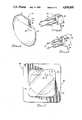
- FIG. 1is an enlarged view of a cardiac pacemaker to which the present invention is related;
- FIG. 2is a perspective view of one particular arrangement in accordance with the present invention.
- FIG. 3is a perspective view of another particular arrangement in accordance with the present invention.
- FIG. 4is a schematic diagram representing circuitry of the present invention in association with a pacemaker like that shown in FIG. 1;
- FIG. 5is a schematic view showing circuitry of another arrangement in accordance with the present invention in association with a pacemaker like that represented in FIG. 1;
- FIG. 6is a schematic diagram representing circuitry of still another arrangement in accordance with the present invention in association with a pacemaker like that shown in FIG. 1;
- FIG. 7is a side view of a pacemaker and a disposable device of the present invention as installed within a sterile package, ready for testing.
- Implantable cardiac pacemakers of the type here involvedhave a housing which is of more or less standard size and shape for those models of pacemakers which are presently being manufactured.
- a typical pacemaker 10is shown in an enlarged view in FIG. 1. Such a pacemaker is approximately the size and weight of a conventional pocket watch.
- the pacemaker 10 of FIG. 1has a housing comprising a metal case 12 to which is affixed a connector top 14, usually formed of plastic.
- the pacemaker 10is shown with a pair of openings 16, 18 in the end wall 20 of the connector top. These openings 16, 18 are the outer ends of bores which extend back into the connector top and are provided to receive the terminal connectors of leads which extend to the patient's heart.
- the pacemakermay be single chamber or dual chamber, unipolar or bipolar, inline or not inline, and a test element configuration in accordance with the present invention may be adapted accordingly to be usable with a given pacemaker.
- FIG. 2shows a particular arrangement of the present invention configured for a dual chamber unipolar pacemaker and corresponds to the circuit arrangement depicted in FIG. 4.
- Device 22is shown with two wire terminal connectors 24, one for each of two pacer outputs, and a pacer return contact 26 which makes contact with the pacemaker case in the region 28 (FIG. 1) when the unit 22 is mounted in place on the pacemaker 10.
- Device 22has a pair of cylindrical hollow rods 21 extending longitudinally from a base portion 30. By means of this arrangement, the rods 21 and the terminal connectors 24 are maintained in the proper orientation to enter the bores 16, 18 of the pacemaker when the device 22 is installed.
- Each cylindrical rodcontains a resistor 32 and a magnetically responsive reed switch 34, interconnected with the return contact 26 as shown in FIG. 4.
- FIG. 5shows a single chamber, bipolar (not inline) pacemaker, wherein the return contact 26 is dispensed with, only one resistor and switch combination 32, 34 is present in one of the cylindrical rod portions 21.
- the other member 21only contains a wire extending from the lower terminal connector 24 and completing the circuit to the reed switch 34.
- FIG. 3shows a test device 36, like the device 22 of FIG. 2 except that the device 36 is provided with added contact elements 38 for use with a dual chamber, inline, bipolar pacer, such as the combination represented schematically in FIG. 6.
- the return contact 26is not in the circuit; it is not used electrically but is included for uniformity of fabrication.
- one of the terminals 24is the pacer output; the other is for the signal return.
- the terminals 24are typically pacer output leads while the connectors 38 correspond to the signal return contacts where they connect into the pacemaker 10.
- FIG. 7shows a combination 40 of a pacemaker 10 as packaged within a sterile pack 42, ready for shipment or for testing in preparation for implantation.
- the in-package test device 22is shown installed on the pacemaker with the terminal connectors inserted into the plastic cap 14.
- the pack 42is shown with a peripheral sealing edge 44 which surrounds the trapped, sterile chamber 46 in which the pacemaker 10 is maintained in a sterile environment.
- the chamber 46typically contains a sterilizing gas which serves to sterilize the pacemaker and its components and to maintain the contents of the chamber sterile as long as the integrity of the package is not disrupted.
- the material of the pack 42is typically of transparent plastic so that the pacemaker is clearly visible within the package.
- faulty connector elements and feedthrough to internal electronics of a package pacercan be detected without opening the sterile package.
- Telemetered interrogation of the packaged paceroccurs with the pacer under load--i.e., in circuit with the series resistor 32 of the test device--yet when the interrogation device is removed, the load is removed from the pacer circuitry upon the opening of the reed switch 34 so that there is no excessive battery drain between the time of manufacture and the time of implantation.
- the surgical implantation teamcan verify electrical functionality of the pacer by the same means before the sterile package is opened.
- the concept of the present inventionis independent of the pacer manufacturer or pacer design, and is readily adaptable to different terminal configurations.
- the only requirementis that a magnetic field must be present to activate the reed swich during telemetered interrogation.
- equivalent devicesproviding the capability of the reed switch may be substituted in the test device circuit(s). For example, a Hall effect switch or some other proximity switch which can open and close an electrical path in response to a remote signal or applied field may be used.
- a light emitting diode (LED) or similar indicatormay also be placed in the circuit, in series with the device as shown, thereby providing a simple, quick diagnostic tool which requires only the presence of a magnetic field to cause activation.
- LEDlight emitting diode
- Other variations in accordance with the present inventionmay be devised.
Landscapes
- Health & Medical Sciences (AREA)
- Cardiology (AREA)
- Heart & Thoracic Surgery (AREA)
- Engineering & Computer Science (AREA)
- Biomedical Technology (AREA)
- Nuclear Medicine, Radiotherapy & Molecular Imaging (AREA)
- Radiology & Medical Imaging (AREA)
- Life Sciences & Earth Sciences (AREA)
- Animal Behavior & Ethology (AREA)
- General Health & Medical Sciences (AREA)
- Public Health (AREA)
- Veterinary Medicine (AREA)
- Electrotherapy Devices (AREA)
Abstract
Description
Claims (16)
Priority Applications (1)
| Application Number | Priority Date | Filing Date | Title |
|---|---|---|---|
| US07/076,952US4830005A (en) | 1987-07-23 | 1987-07-23 | Disposable in-package load test element for pacemakers |
Applications Claiming Priority (1)
| Application Number | Priority Date | Filing Date | Title |
|---|---|---|---|
| US07/076,952US4830005A (en) | 1987-07-23 | 1987-07-23 | Disposable in-package load test element for pacemakers |
Publications (1)
| Publication Number | Publication Date |
|---|---|
| US4830005Atrue US4830005A (en) | 1989-05-16 |
Family
ID=22135194
Family Applications (1)
| Application Number | Title | Priority Date | Filing Date |
|---|---|---|---|
| US07/076,952Expired - LifetimeUS4830005A (en) | 1987-07-23 | 1987-07-23 | Disposable in-package load test element for pacemakers |
Country Status (1)
| Country | Link |
|---|---|
| US (1) | US4830005A (en) |
Cited By (77)
| Publication number | Priority date | Publication date | Assignee | Title |
|---|---|---|---|---|
| US5237991A (en)* | 1991-11-19 | 1993-08-24 | Cyberonics, Inc. | Implantable medical device with dummy load for pre-implant testing in sterile package and facilitating electrical lead connection |
| US5314452A (en)* | 1991-09-23 | 1994-05-24 | Siemens Aktiengesellschaft | Protective arrangement for an implantable defibrillator |
| US5350407A (en)* | 1992-12-30 | 1994-09-27 | Telectronics Pacing Systems, Inc. | Implantable stimulator having quiescent and active modes of operation |
| EP0775503A3 (en)* | 1995-11-22 | 1998-04-15 | INCONTROL, Inc. | System and method for implanting an implantable cardiac device |
| US6292697B1 (en) | 2000-02-15 | 2001-09-18 | Medtronic, Inc. | Testing sterile packaged components of an implantable medical device prior to chronic implantation |
| US20020035380A1 (en)* | 2000-09-18 | 2002-03-21 | Cameron Health, Inc. | Power supply for an implantable subcutaneous cardioverter-defibrillator |
| US6370432B1 (en) | 1999-08-20 | 2002-04-09 | Cardiac Pacemakers, Inc. | Pacemaker passive measurement testing system and method |
| US20020042629A1 (en)* | 2000-09-18 | 2002-04-11 | Cameron Health, Inc. | Cardioverter-defibrillator having a focused shocking area and orientation thereof |
| US20020049476A1 (en)* | 2000-09-18 | 2002-04-25 | Cameron Health, Inc. | Biphasic waveform anti-bradycardia pacing for a subcutaneous implantable cardioverter-defibrillator |
| US20020052636A1 (en)* | 2000-09-18 | 2002-05-02 | Cameron Health, Inc. | Subcutaneous electrode for transthoracic conduction with low-profile installation appendage and method of doing same |
| WO2002022208A3 (en)* | 2000-09-18 | 2002-06-06 | Cameron Health Inc | Subcutaneous only implantable cardioverter-defibrillator and optional pacer |
| US20020091414A1 (en)* | 2000-09-18 | 2002-07-11 | Cameron Health, Inc. | Monophasic waveform for anti-bradycardia pacing for a subcutaneous implantable cardioverter-defibrillator |
| US20020107544A1 (en)* | 2000-09-18 | 2002-08-08 | Cameron Health, Inc. | Current waveform for anti-bradycardia pacing for a subcutaneous implantable cardioverter-defibrillator |
| US20020107546A1 (en)* | 2000-09-18 | 2002-08-08 | Cameron Health, Inc. | Packaging technology for non-transvenous cardioverter/defibrillator devices |
| US20020120299A1 (en)* | 2000-09-18 | 2002-08-29 | Cameron Health, Inc. | Current waveforms for anti-tachycardia pacing for a subcutaneous implantable cardioverter- defibrillator |
| US20030045904A1 (en)* | 2000-09-18 | 2003-03-06 | Bardy Gust H. | Subcutaneous cardiac stimulator device and method generating uniform electric field through the heart |
| US20030088282A1 (en)* | 2001-11-05 | 2003-05-08 | Cameron Health, Inc. | Defibrillation pacing circuitry |
| US20030088280A1 (en)* | 2001-11-05 | 2003-05-08 | Cameron Health, Inc. | Low power A/D converter |
| US20030088278A1 (en)* | 2000-09-18 | 2003-05-08 | Cameron Health, Inc. | Optional use of a lead for a unitary subcutaneous implantable cardioverter-defibrillator |
| US20030088283A1 (en)* | 2001-11-05 | 2003-05-08 | Ostroff Alan H. | Simplified defibrillator output circuit |
| US6647292B1 (en) | 2000-09-18 | 2003-11-11 | Cameron Health | Unitary subcutaneous only implantable cardioverter-defibrillator and optional pacer |
| US20040068303A1 (en)* | 2002-10-04 | 2004-04-08 | Ostroff Alan H. | Implantable cardiac system with a selectable active housing |
| US6754528B2 (en) | 2001-11-21 | 2004-06-22 | Cameraon Health, Inc. | Apparatus and method of arrhythmia detection in a subcutaneous implantable cardioverter/defibrillator |
| US6778860B2 (en) | 2001-11-05 | 2004-08-17 | Cameron Health, Inc. | Switched capacitor defibrillation circuit |
| US20040186529A1 (en)* | 2000-09-18 | 2004-09-23 | Cameron Health, Inc. | Subcutaneous electrode for transthoracic conduction with highly maneuverable insertion tool |
| US20040199082A1 (en)* | 2003-04-03 | 2004-10-07 | Ostroff Alan H. | Selctable notch filter circuits |
| US20040210293A1 (en)* | 2000-09-18 | 2004-10-21 | Cameron Health, Inc. | Subcutaneous electrode for transthoracic conduction with insertion tool |
| US20040215308A1 (en)* | 2000-09-18 | 2004-10-28 | Cameron Health, Inc. | Subcutaneous electrode with improved contact shape for transthoracic conduction |
| US20040254611A1 (en)* | 2003-06-02 | 2004-12-16 | Cameron Health, Inc. | Method and devices for performing cardiac waveform appraisal |
| US6834204B2 (en) | 2001-11-05 | 2004-12-21 | Cameron Health, Inc. | Method and apparatus for inducing defibrillation in a patient using a T-shock waveform |
| US20040260353A1 (en)* | 2000-09-18 | 2004-12-23 | Cameron Health, Inc. | Radian curve shaped implantable cardioverter-defibrillator canister |
| US6856835B2 (en) | 2000-09-18 | 2005-02-15 | Cameron Health, Inc. | Biphasic waveform for anti-tachycardia pacing for a subcutaneous implantable cardioverter-defibrillator |
| US20050049644A1 (en)* | 2001-11-21 | 2005-03-03 | Cameron Health, Inc. | Multiple electrode vectors for implantable cardiac treatment devices |
| US6865417B2 (en) | 2001-11-05 | 2005-03-08 | Cameron Health, Inc. | H-bridge with sensing circuit |
| US6866044B2 (en) | 2000-09-18 | 2005-03-15 | Cameron Health, Inc. | Method of insertion and implantation of implantable cardioverter-defibrillator canisters |
| US20050107835A1 (en)* | 2000-09-18 | 2005-05-19 | Cameron Health, Inc. | Ceramics and/or other material insulated shell for active and non-active S-ICD can |
| US20050131464A1 (en)* | 2000-11-22 | 2005-06-16 | Heinrich Stephen D. | Apparatus for detecting and treating ventricular arrhythmia |
| US20050192639A1 (en)* | 2000-09-18 | 2005-09-01 | Cameron Health, Inc. | Flexible subcutaneous implantable cardioverter-defibrillator |
| US20050192505A1 (en)* | 2001-11-21 | 2005-09-01 | Cameron Health, Inc. | Method for discriminating between ventricular and supraventricular arrhythmias |
| US6950705B2 (en) | 2000-09-18 | 2005-09-27 | Cameron Health, Inc. | Canister designs for implantable cardioverter-defibrillators |
| US20060001070A1 (en)* | 2004-05-03 | 2006-01-05 | Samsung Electronics Co., Ltd. | Capacitor of a memory device and fabrication method thereof |
| US20060025826A1 (en)* | 2000-09-18 | 2006-02-02 | Cameron Health, Inc. | Subcutaneous implantable cardioverter-defibrillator employing a telescoping lead |
| US20060089681A1 (en)* | 2004-10-21 | 2006-04-27 | Cameron Health, Inc. | Implantable medical device |
| US20060116595A1 (en)* | 2004-11-29 | 2006-06-01 | Cameron Health, Inc. | Method for defining signal templates in implantable cardiac devices |
| US20060116725A1 (en)* | 2004-11-29 | 2006-06-01 | Cameron Health, Inc. | Method and apparatus for beat alignment and comparison |
| US20060122652A1 (en)* | 2004-11-05 | 2006-06-08 | Das Stephen D | Test method and apparatus for verification of medical device functionality |
| US20060122676A1 (en)* | 2004-12-06 | 2006-06-08 | Cameron Health, Inc. | Apparatus and method for subcutaneous electrode insertion |
| US7065407B2 (en) | 2000-09-18 | 2006-06-20 | Cameron Health, Inc. | Duckbill-shaped implantable cardioverter-defibrillator canister and method of use |
| US20060167503A1 (en)* | 2005-01-25 | 2006-07-27 | Cameron Health, Inc. | Method for adapting charge initiation for an implantable cardioverter-defibrillator |
| US20060167504A1 (en)* | 2005-01-25 | 2006-07-27 | Cameron Health, Inc. | Devices for adapting charge initiation for an implantable cardioverter-defibrillator |
| US7090682B2 (en) | 2000-09-18 | 2006-08-15 | Cameron Health, Inc. | Method and apparatus for extraction of a subcutaneous electrode |
| US20060241698A1 (en)* | 2005-04-26 | 2006-10-26 | Cameron Health, Inc. | Methods and implantable devices for inducing fibrillation by alternating constant current |
| US7149575B2 (en) | 2000-09-18 | 2006-12-12 | Cameron Health, Inc. | Subcutaneous cardiac stimulator device having an anteriorly positioned electrode |
| US20070032829A1 (en)* | 2005-08-04 | 2007-02-08 | Cameron Health, Inc. | Methods and devices for tachyarrhythmia sensing and high-pass filter bypass |
| US20070049979A1 (en)* | 2000-09-18 | 2007-03-01 | Cameron Health, Inc. | Bradycardia pacing in a subcutaneous device |
| US20070119741A1 (en)* | 2005-11-30 | 2007-05-31 | Wenger William K | Medical device packaging system |
| US7239925B2 (en) | 2000-09-18 | 2007-07-03 | Cameron Health, Inc. | Subcutaneous electrode for transthoracic conduction with improved installation characteristics |
| US20070276452A1 (en)* | 2006-05-26 | 2007-11-29 | Cameron Health, Inc. | Implantable medical device systems having initialization functions and methods of operation |
| US20070276445A1 (en)* | 2006-05-26 | 2007-11-29 | Cameron Health, Inc. | Systems and methods for sensing vector selection in an implantable medical device |
| US20080015644A1 (en)* | 2006-07-14 | 2008-01-17 | Cameron Health, Inc. | End of life battery testing in an implantable medical device |
| US20080077030A1 (en)* | 2006-09-26 | 2008-03-27 | Cameron Health, Inc. | Signal analysis in implantable cardiac treatment devices |
| US20080154350A1 (en)* | 2006-12-20 | 2008-06-26 | Cameron Health, Inc. | Implantable cardiac stimulus devices and methods with input recharge circuitry |
| US20080172100A1 (en)* | 2007-01-16 | 2008-07-17 | Cameron Health, Inc. | Systems and methods for sensing vector selection in an implantable medical device using a polynomial approach |
| US20080188901A1 (en)* | 2007-02-07 | 2008-08-07 | Cameron Health, Inc. | Sensing vector selection in a cardiac stimulus device with postural assessment |
| WO2008130292A1 (en)* | 2007-04-24 | 2008-10-30 | St. Jude Medical Ab | A system, an apparatus and a container for storing an implantable medical device, and a method for packaging such a device |
| US20090132009A1 (en)* | 2007-11-21 | 2009-05-21 | Medtronic, Inc. | Determination of stimulation output capabilities throughout power source voltage range |
| US20090276004A1 (en)* | 2008-04-30 | 2009-11-05 | Kronich Christine G | Lead Implant System |
| US7623913B2 (en) | 2006-08-01 | 2009-11-24 | Cameron Health, Inc. | Implantable medical devices using heuristic filtering in cardiac event detection |
| US7623909B2 (en) | 2006-05-26 | 2009-11-24 | Cameron Health, Inc. | Implantable medical devices and programmers adapted for sensing vector selection |
| US20100114257A1 (en)* | 2008-10-31 | 2010-05-06 | Medtronic, Inc. | Determination of stimulation output capabilities throughout power source voltage range |
| US7877139B2 (en) | 2006-09-22 | 2011-01-25 | Cameron Health, Inc. | Method and device for implantable cardiac stimulus device lead impedance measurement |
| US8718793B2 (en) | 2006-08-01 | 2014-05-06 | Cameron Health, Inc. | Electrode insertion tools, lead assemblies, kits and methods for placement of cardiac device electrodes |
| US9149645B2 (en) | 2013-03-11 | 2015-10-06 | Cameron Health, Inc. | Methods and devices implementing dual criteria for arrhythmia detection |
| US9212981B2 (en) | 2012-12-07 | 2015-12-15 | Purdue Research Foundation | Feedback system and method for assessing fixation and stability of implantable leads |
| US9340342B2 (en) | 2014-07-28 | 2016-05-17 | Energizer Brands, Llc | Product packaging having magnetic activated test mode |
| US9469437B2 (en) | 2013-01-18 | 2016-10-18 | Cyberonics, Inc. | Radiofrequency shielded container |
| US9579065B2 (en) | 2013-03-12 | 2017-02-28 | Cameron Health Inc. | Cardiac signal vector selection with monophasic and biphasic shape consideration |
Citations (7)
| Publication number | Priority date | Publication date | Assignee | Title |
|---|---|---|---|---|
| US3508538A (en)* | 1967-11-22 | 1970-04-28 | Cordis Corp | Method and apparatus for positioning the ventricular lead of a cardiac pacer |
| US3625201A (en)* | 1969-11-28 | 1971-12-07 | Cordis Corp | Tester for standby cardiac pacing |
| US3798542A (en)* | 1972-07-05 | 1974-03-19 | R Dempsey | Energy measuring device for pulse type defibrillators |
| US4423732A (en)* | 1980-09-26 | 1984-01-03 | Cordis Corporation | Sterile connector system for packaged pacer |
| US4476869A (en)* | 1980-06-05 | 1984-10-16 | Intermedics, Inc. | Pacer analyzer |
| US4605007A (en)* | 1980-06-02 | 1986-08-12 | Medtronic, Inc. | Temporary package for an electrical component |
| US4705042A (en)* | 1985-05-21 | 1987-11-10 | Cordis Corporation | Pacing system analyzer having provision for direct connection of pacer to pacing leads |
- 1987
- 1987-07-23USUS07/076,952patent/US4830005A/ennot_activeExpired - Lifetime
Patent Citations (7)
| Publication number | Priority date | Publication date | Assignee | Title |
|---|---|---|---|---|
| US3508538A (en)* | 1967-11-22 | 1970-04-28 | Cordis Corp | Method and apparatus for positioning the ventricular lead of a cardiac pacer |
| US3625201A (en)* | 1969-11-28 | 1971-12-07 | Cordis Corp | Tester for standby cardiac pacing |
| US3798542A (en)* | 1972-07-05 | 1974-03-19 | R Dempsey | Energy measuring device for pulse type defibrillators |
| US4605007A (en)* | 1980-06-02 | 1986-08-12 | Medtronic, Inc. | Temporary package for an electrical component |
| US4476869A (en)* | 1980-06-05 | 1984-10-16 | Intermedics, Inc. | Pacer analyzer |
| US4423732A (en)* | 1980-09-26 | 1984-01-03 | Cordis Corporation | Sterile connector system for packaged pacer |
| US4705042A (en)* | 1985-05-21 | 1987-11-10 | Cordis Corporation | Pacing system analyzer having provision for direct connection of pacer to pacing leads |
Cited By (219)
| Publication number | Priority date | Publication date | Assignee | Title |
|---|---|---|---|---|
| US5314452A (en)* | 1991-09-23 | 1994-05-24 | Siemens Aktiengesellschaft | Protective arrangement for an implantable defibrillator |
| US5237991A (en)* | 1991-11-19 | 1993-08-24 | Cyberonics, Inc. | Implantable medical device with dummy load for pre-implant testing in sterile package and facilitating electrical lead connection |
| US5350407A (en)* | 1992-12-30 | 1994-09-27 | Telectronics Pacing Systems, Inc. | Implantable stimulator having quiescent and active modes of operation |
| EP0775503A3 (en)* | 1995-11-22 | 1998-04-15 | INCONTROL, Inc. | System and method for implanting an implantable cardiac device |
| US6370432B1 (en) | 1999-08-20 | 2002-04-09 | Cardiac Pacemakers, Inc. | Pacemaker passive measurement testing system and method |
| US8639337B2 (en) | 1999-08-20 | 2014-01-28 | Cardiac Pacemakers, Inc. | Pacemaker passive measurement testing system |
| US6845269B2 (en) | 1999-08-20 | 2005-01-18 | Cardiac Pacemakers, Inc. | Pacemaker passive measurement testing system and method |
| US8046071B2 (en) | 1999-08-20 | 2011-10-25 | Cardiac Pacemakers, Inc. | Pacemaker passive measurement testing system |
| US20100204746A1 (en)* | 1999-08-20 | 2010-08-12 | Conley Vickie L | Pacemaker passive measurement testing system and method |
| US7729765B2 (en) | 1999-08-20 | 2010-06-01 | Cardiac Pacemakers, Inc. | Pacemaker passive measurement testing system and method |
| US20070073349A1 (en)* | 1999-08-20 | 2007-03-29 | Cardiac Pacemakers, Inc. | Pacemaker passive measurement testing system and method |
| US7149580B2 (en) | 1999-08-20 | 2006-12-12 | Cardiac Pacemakers, Inc. | Pacemaker passive measurement testing system and method |
| US20050102004A1 (en)* | 1999-08-20 | 2005-05-12 | Cardiac Pacemakers, Inc. | Pacemaker passive measurement testing system and method |
| US6292697B1 (en) | 2000-02-15 | 2001-09-18 | Medtronic, Inc. | Testing sterile packaged components of an implantable medical device prior to chronic implantation |
| US7720536B2 (en) | 2000-09-18 | 2010-05-18 | Cameron Health, Inc. | Power supply for an implantable subcutaneous cardioverter-defibrillator |
| US7813797B2 (en) | 2000-09-18 | 2010-10-12 | Cameron Health, Inc. | Cardioverter-defibrillator having a focused shocking area and orientation thereof |
| US7299097B2 (en) | 2000-09-18 | 2007-11-20 | Cameron Health, Inc. | Subcutaneous electrode for transthoracic conduction with insertion tool |
| US20020120299A1 (en)* | 2000-09-18 | 2002-08-29 | Cameron Health, Inc. | Current waveforms for anti-tachycardia pacing for a subcutaneous implantable cardioverter- defibrillator |
| US20030045904A1 (en)* | 2000-09-18 | 2003-03-06 | Bardy Gust H. | Subcutaneous cardiac stimulator device and method generating uniform electric field through the heart |
| US9144683B2 (en) | 2000-09-18 | 2015-09-29 | Cameron Health, Inc. | Post-shock treatment in a subcutaneous device |
| EP2764892A1 (en)* | 2000-09-18 | 2014-08-13 | Cameron Health, Inc. | Subcutaneous only implantable cardioverter-defibrillator and optional pacer |
| US20030088278A1 (en)* | 2000-09-18 | 2003-05-08 | Cameron Health, Inc. | Optional use of a lead for a unitary subcutaneous implantable cardioverter-defibrillator |
| US20020035380A1 (en)* | 2000-09-18 | 2002-03-21 | Cameron Health, Inc. | Power supply for an implantable subcutaneous cardioverter-defibrillator |
| US6647292B1 (en) | 2000-09-18 | 2003-11-11 | Cameron Health | Unitary subcutaneous only implantable cardioverter-defibrillator and optional pacer |
| US8447398B2 (en) | 2000-09-18 | 2013-05-21 | Cameron Health, Inc. | Subcutaneous implantable cardioverter-defibrillator placement methods |
| US6721597B1 (en) | 2000-09-18 | 2004-04-13 | Cameron Health, Inc. | Subcutaneous only implantable cardioverter defibrillator and optional pacer |
| US8412320B2 (en) | 2000-09-18 | 2013-04-02 | Cameron Health, Inc. | Nontransvenous and nonepicardial methods of cardiac treatment and stimulus |
| US7302300B2 (en) | 2000-09-18 | 2007-11-27 | Cameron Health, Inc. | Subcutaneous electrode for transthoracic conduction with highly maneuverable insertion tool |
| US20040172071A1 (en)* | 2000-09-18 | 2004-09-02 | Cameron Health, Inc. | Subcutaneous only implantable cardioverter-defibrillator and optional pacer |
| US20040186529A1 (en)* | 2000-09-18 | 2004-09-23 | Cameron Health, Inc. | Subcutaneous electrode for transthoracic conduction with highly maneuverable insertion tool |
| US8160699B2 (en) | 2000-09-18 | 2012-04-17 | Cameron Health, Inc. | Cardioverter-defibrillator having a focused shocking area and orientation thereof |
| US20040210294A1 (en)* | 2000-09-18 | 2004-10-21 | Cameron Health, Inc. | Subcutaneous electrode for transthoracic conduction with low profile installation appendage |
| US20040210293A1 (en)* | 2000-09-18 | 2004-10-21 | Cameron Health, Inc. | Subcutaneous electrode for transthoracic conduction with insertion tool |
| US20040215308A1 (en)* | 2000-09-18 | 2004-10-28 | Cameron Health, Inc. | Subcutaneous electrode with improved contact shape for transthoracic conduction |
| US20020042629A1 (en)* | 2000-09-18 | 2002-04-11 | Cameron Health, Inc. | Cardioverter-defibrillator having a focused shocking area and orientation thereof |
| US8014862B2 (en) | 2000-09-18 | 2011-09-06 | Cameron Health, Inc. | Anterior active housing subcutaneous positioning methods |
| US7835790B2 (en) | 2000-09-18 | 2010-11-16 | Cameron Health, Inc. | Anterior active housing subcutaneous positioning methods |
| US20040260353A1 (en)* | 2000-09-18 | 2004-12-23 | Cameron Health, Inc. | Radian curve shaped implantable cardioverter-defibrillator canister |
| US20050010251A9 (en)* | 2000-09-18 | 2005-01-13 | Cameron Health, Inc. | Optional use of a lead for a unitary subcutaneous implantable cardioverter-defibrillator |
| US20020107544A1 (en)* | 2000-09-18 | 2002-08-08 | Cameron Health, Inc. | Current waveform for anti-bradycardia pacing for a subcutaneous implantable cardioverter-defibrillator |
| US6856835B2 (en) | 2000-09-18 | 2005-02-15 | Cameron Health, Inc. | Biphasic waveform for anti-tachycardia pacing for a subcutaneous implantable cardioverter-defibrillator |
| US20050049643A9 (en)* | 2000-09-18 | 2005-03-03 | Cameron Health, Inc. | Power supply for a subcutaneous implantable cardioverter-defibrillator |
| US20020107546A1 (en)* | 2000-09-18 | 2002-08-08 | Cameron Health, Inc. | Packaging technology for non-transvenous cardioverter/defibrillator devices |
| US20020049476A1 (en)* | 2000-09-18 | 2002-04-25 | Cameron Health, Inc. | Biphasic waveform anti-bradycardia pacing for a subcutaneous implantable cardioverter-defibrillator |
| US6866044B2 (en) | 2000-09-18 | 2005-03-15 | Cameron Health, Inc. | Method of insertion and implantation of implantable cardioverter-defibrillator canisters |
| US7299092B2 (en) | 2000-09-18 | 2007-11-20 | Cameron Health, Inc. | Subcutaneous electrode for transthoracic conduction with low profile installation appendage |
| US20020107545A1 (en)* | 2000-09-18 | 2002-08-08 | Cameron Health, Inc. | Power supply for a subcutaneous implantable cardioverter-defibrillator |
| US20050107835A1 (en)* | 2000-09-18 | 2005-05-19 | Cameron Health, Inc. | Ceramics and/or other material insulated shell for active and non-active S-ICD can |
| US20050119705A9 (en)* | 2000-09-18 | 2005-06-02 | Cameron Health, Inc. | Cardioverter-defibrillator having a focused shocking area and orientation thereof |
| US7774059B2 (en) | 2000-09-18 | 2010-08-10 | Cameron Health | Anterior positioning inactive housing |
| US7774058B2 (en) | 2000-09-18 | 2010-08-10 | Cameron Health, Inc. | Anterior positioning on opposing sides of sternum |
| US20050137637A1 (en)* | 2000-09-18 | 2005-06-23 | Cameron Health, Inc. | Biphasic waveform for anti-tachycardia pacing for a subcutaneous implantable cardioverter-defibrillator |
| US20050137625A1 (en)* | 2000-09-18 | 2005-06-23 | Cameron Health, Inc. | Power supply for a subcutaneous implantable cardioverter-defibrillator |
| US7751885B2 (en) | 2000-09-18 | 2010-07-06 | Cameron Health, Inc. | Bradycardia pacing in a subcutaneous device |
| US20050143778A1 (en)* | 2000-09-18 | 2005-06-30 | Cameron Health, Inc. | Current waveforms for anti-bradycardia pacing for a subcutaneous implantable cardioverter-defibrillator |
| US20020052636A1 (en)* | 2000-09-18 | 2002-05-02 | Cameron Health, Inc. | Subcutaneous electrode for transthoracic conduction with low-profile installation appendage and method of doing same |
| US6937907B2 (en) | 2000-09-18 | 2005-08-30 | Cameron Health, Inc. | Subcutaneous electrode for transthoracic conduction with low-profile installation appendage and method of doing same |
| WO2002022208A3 (en)* | 2000-09-18 | 2002-06-06 | Cameron Health Inc | Subcutaneous only implantable cardioverter-defibrillator and optional pacer |
| US20050192639A1 (en)* | 2000-09-18 | 2005-09-01 | Cameron Health, Inc. | Flexible subcutaneous implantable cardioverter-defibrillator |
| US7720534B2 (en) | 2000-09-18 | 2010-05-18 | Cameron Health, Inc. | Transthoracic impedance measurement in a subcutaneous device |
| US6950705B2 (en) | 2000-09-18 | 2005-09-27 | Cameron Health, Inc. | Canister designs for implantable cardioverter-defibrillators |
| US6952610B2 (en) | 2000-09-18 | 2005-10-04 | Cameron Health, Inc. | Current waveforms for anti-tachycardia pacing for a subcutaneous implantable cardioverter- defibrillator |
| US7657322B2 (en) | 2000-09-18 | 2010-02-02 | Cameron Health, Inc. | Subcutaneous electrode with improved contact shape for transthoracic conduction |
| US7657311B2 (en) | 2000-09-18 | 2010-02-02 | Cameron Health, Inc. | Subcutaneous only implantable cardioverter-defibrillator and optional pacer |
| US20050277990A1 (en)* | 2000-09-18 | 2005-12-15 | Cameron Health, Inc. | Current waveforms for anti-tachycardia pacing for a subcutaneous implantable cardioverter-defibrillator |
| US7627375B2 (en) | 2000-09-18 | 2009-12-01 | Cameron Health, Inc. | Implantable cardiac stimulus methods |
| US20060004416A1 (en)* | 2000-09-18 | 2006-01-05 | Cameron Health, Inc. | Canister designs for implantable cardioverter-defibrillators |
| US7536222B2 (en) | 2000-09-18 | 2009-05-19 | Cameron Health, Inc. | Nonvascular implantable defibrillator and method |
| US7502645B2 (en) | 2000-09-18 | 2009-03-10 | Cameron Health, Inc. | Current waveforms for anti-bradycardia pacing for a subcutaneous implantable cardioverter-defibrillator |
| US6988003B2 (en) | 2000-09-18 | 2006-01-17 | Cameron Health, Inc. | Implantable cardioverter-defibrillator having two spaced apart shocking electrodes on housing |
| US20060025826A1 (en)* | 2000-09-18 | 2006-02-02 | Cameron Health, Inc. | Subcutaneous implantable cardioverter-defibrillator employing a telescoping lead |
| US20060036289A1 (en)* | 2000-09-18 | 2006-02-16 | Cameron Health, Inc. | Optional use of a lead for a unitary subcutaneous implantable cardioverter-defibrillator |
| US7463924B2 (en) | 2000-09-18 | 2008-12-09 | Cameron Health, Inc. | Methods for determining placement of an implantable cardiac stimulus device |
| US7039465B2 (en) | 2000-09-18 | 2006-05-02 | Cameron Health, Inc. | Ceramics and/or other material insulated shell for active and non-active S-ICD can |
| US7039459B2 (en) | 2000-09-18 | 2006-05-02 | Cameron Health, Inc. | Cardioverter-defibrillator having a focused shocking area and orientation thereof |
| US7043299B2 (en) | 2000-09-18 | 2006-05-09 | Cameron Health, Inc. | Subcutaneous implantable cardioverter-defibrillator employing a telescoping lead |
| US7428437B2 (en) | 2000-09-18 | 2008-09-23 | Cameron Health, Inc. | Canister designs for implantable cardioverter-defibrillators |
| US7406350B2 (en) | 2000-09-18 | 2008-07-29 | Cameron Health, Inc. | Subcutaneous implantable cardioverter-defibrillator employing a telescoping lead |
| US7363083B2 (en) | 2000-09-18 | 2008-04-22 | Cameron Health, Inc. | Flexible subcutaneous implantable cardioverter-defibrillator |
| US7359754B2 (en) | 2000-09-18 | 2008-04-15 | Cameron Health, Inc. | Optional use of a lead for a unitary subcutaneous implantable cardioverter-defibrillator |
| US7349736B2 (en) | 2000-09-18 | 2008-03-25 | Cameron Health, Inc. | Active housing dual lead assembly |
| US7065407B2 (en) | 2000-09-18 | 2006-06-20 | Cameron Health, Inc. | Duckbill-shaped implantable cardioverter-defibrillator canister and method of use |
| US7065410B2 (en) | 2000-09-18 | 2006-06-20 | Cameron Health, Inc. | Subcutaneous electrode with improved contact shape for transthorasic conduction |
| US7069080B2 (en) | 2000-09-18 | 2006-06-27 | Cameron Health, Inc. | Active housing and subcutaneous electrode cardioversion/defibrillating system |
| US7076296B2 (en) | 2000-09-18 | 2006-07-11 | Cameron Health, Inc. | Method of supplying energy to subcutaneous cardioverter-defibrillator and pacer |
| US7076294B2 (en) | 2000-09-18 | 2006-07-11 | Cameron Health, Inc. | Method of implanting ICD and subcutaneous lead |
| US20050065559A1 (en)* | 2000-09-18 | 2005-03-24 | Cameron Health, Inc. | Monophasic waveform for anti-tachycardia pacing for a subcutaneous implantable cardioverter-defibrillator |
| US20020107548A1 (en)* | 2000-09-18 | 2002-08-08 | Cameron Health, Inc. | Cardioverter-defibrillator having a focused shocking area and orientation thereof |
| US7092754B2 (en) | 2000-09-18 | 2006-08-15 | Cameron Health, Inc. | Monophasic waveform for anti-bradycardia pacing for a subcutaneous implantable cardioverter-defibrillator |
| US7090682B2 (en) | 2000-09-18 | 2006-08-15 | Cameron Health, Inc. | Method and apparatus for extraction of a subcutaneous electrode |
| US7120496B2 (en) | 2000-09-18 | 2006-10-10 | Cameron Health, Inc. | Radian curve shaped implantable cardioverter-defibrillator canister |
| US7120495B2 (en) | 2000-09-18 | 2006-10-10 | Cameron Health, Inc. | Flexible subcutaneous implantable cardioverter-defibrillator |
| US20060229682A1 (en)* | 2000-09-18 | 2006-10-12 | Cameron Health, Inc. | Power supply for an implantable subcutaneous cardioverter-defibrillator |
| US20060235479A1 (en)* | 2000-09-18 | 2006-10-19 | Cameron Health, Inc. | Monophasic waveform for anti-bradycardia pacing for a subcutaneous implantable cardioverter-defibrillator |
| US7274962B2 (en) | 2000-09-18 | 2007-09-25 | Cameron Health, Inc. | Subcutaneous electrode with improved contact shape for transthoracic conduction |
| US7146212B2 (en) | 2000-09-18 | 2006-12-05 | Cameron Health, Inc. | Anti-bradycardia pacing for a subcutaneous implantable cardioverter-defibrillator |
| US20020095184A1 (en)* | 2000-09-18 | 2002-07-18 | Bardy Gust H. | Monophasic waveform for anti-tachycardia pacing for a subcutaneous implantable cardioverter-defibrillator |
| US7149575B2 (en) | 2000-09-18 | 2006-12-12 | Cameron Health, Inc. | Subcutaneous cardiac stimulator device having an anteriorly positioned electrode |
| US20070021791A1 (en)* | 2000-09-18 | 2007-01-25 | Cameron Health, Inc. | Transthoracic impedance measurement in a subcutaneous device |
| US7239925B2 (en) | 2000-09-18 | 2007-07-03 | Cameron Health, Inc. | Subcutaneous electrode for transthoracic conduction with improved installation characteristics |
| US7181274B2 (en) | 2000-09-18 | 2007-02-20 | Cameron Health, Inc. | Methods for inducing fibrillation utilizing subcutaneous electrodes |
| US20070049979A1 (en)* | 2000-09-18 | 2007-03-01 | Cameron Health, Inc. | Bradycardia pacing in a subcutaneous device |
| US20070055309A1 (en)* | 2000-09-18 | 2007-03-08 | Cameron Health, Inc. | Active housing dual lead assembly |
| US20070060960A1 (en)* | 2000-09-18 | 2007-03-15 | Cameron Health, Inc. | Anterior active housing subcutaneous positioning methods |
| US20070060958A1 (en)* | 2000-09-18 | 2007-03-15 | Cameron Health, Inc. | Anterior positioning inactive housing |
| US20070060957A1 (en)* | 2000-09-18 | 2007-03-15 | Cameron Health, Inc. | Anterior positioning on opposing sides of sternum |
| US7194302B2 (en) | 2000-09-18 | 2007-03-20 | Cameron Health, Inc. | Subcutaneous cardiac stimulator with small contact surface electrodes |
| US7194309B2 (en) | 2000-09-18 | 2007-03-20 | Cameron Health, Inc. | Packaging technology for non-transvenous cardioverter/defibrillator devices |
| US20070142865A1 (en)* | 2000-09-18 | 2007-06-21 | Cameron Health, Inc. | Subcutaneous Implantable Cardioverter-Defibrillator Placement Methods |
| US20020091414A1 (en)* | 2000-09-18 | 2002-07-11 | Cameron Health, Inc. | Monophasic waveform for anti-bradycardia pacing for a subcutaneous implantable cardioverter-defibrillator |
| US20050143776A1 (en)* | 2000-11-22 | 2005-06-30 | Cardiac Pacemakers, Inc. | Apparatus for detecting and treating ventricular arrhythmia |
| US20050131464A1 (en)* | 2000-11-22 | 2005-06-16 | Heinrich Stephen D. | Apparatus for detecting and treating ventricular arrhythmia |
| US9022962B2 (en) | 2000-11-22 | 2015-05-05 | Boston Scientific Scimed, Inc. | Apparatus for detecting and treating ventricular arrhythmia |
| US20030088282A1 (en)* | 2001-11-05 | 2003-05-08 | Cameron Health, Inc. | Defibrillation pacing circuitry |
| US20050131466A1 (en)* | 2001-11-05 | 2005-06-16 | Cameron Health, Inc. | H-bridge with sensing circuit |
| US6954670B2 (en) | 2001-11-05 | 2005-10-11 | Cameron Health, Inc. | Simplified defibrillator output circuit |
| US6952608B2 (en) | 2001-11-05 | 2005-10-04 | Cameron Health, Inc. | Defibrillation pacing circuitry |
| US20050288714A1 (en)* | 2001-11-05 | 2005-12-29 | Cameron Health, Inc. | Defibrillation pacing circuitry |
| US9522284B2 (en) | 2001-11-05 | 2016-12-20 | Cameron Health Inc. | Defibrillation pacing circuitry |
| US7623920B2 (en) | 2001-11-05 | 2009-11-24 | Cameron Health, Inc. | Low power A/D converter |
| US6778860B2 (en) | 2001-11-05 | 2004-08-17 | Cameron Health, Inc. | Switched capacitor defibrillation circuit |
| US6927721B2 (en) | 2001-11-05 | 2005-08-09 | Cameron Health, Inc. | Low power A/D converter |
| US20070179537A1 (en)* | 2001-11-05 | 2007-08-02 | Cameron Health, Inc. | Implantable Cardioverter-Defibrillator With Post-Shock Reset |
| US6865417B2 (en) | 2001-11-05 | 2005-03-08 | Cameron Health, Inc. | H-bridge with sensing circuit |
| US7194303B2 (en) | 2001-11-05 | 2007-03-20 | Cameron Health, Inc. | H-bridge with sensing circuit |
| US20030088280A1 (en)* | 2001-11-05 | 2003-05-08 | Cameron Health, Inc. | Low power A/D converter |
| US6834204B2 (en) | 2001-11-05 | 2004-12-21 | Cameron Health, Inc. | Method and apparatus for inducing defibrillation in a patient using a T-shock waveform |
| US20030088283A1 (en)* | 2001-11-05 | 2003-05-08 | Ostroff Alan H. | Simplified defibrillator output circuit |
| US7522957B2 (en) | 2001-11-05 | 2009-04-21 | Cameron Health, Inc. | Defibrillation pacing circuitry |
| US20060009807A1 (en)* | 2001-11-05 | 2006-01-12 | Cameron Health, Inc. | Simplified defibrillator output circuit |
| US7389139B2 (en) | 2001-11-05 | 2008-06-17 | Cameron Health, Inc. | Simplified defibrillator output circuit |
| US7769445B2 (en) | 2001-11-05 | 2010-08-03 | Cameron Health, Inc. | Implantable cardioverter-defibrillator with post-shock reset |
| US7330757B2 (en) | 2001-11-21 | 2008-02-12 | Cameron Health, Inc. | Method for discriminating between ventricular and supraventricular arrhythmias |
| US6754528B2 (en) | 2001-11-21 | 2004-06-22 | Cameraon Health, Inc. | Apparatus and method of arrhythmia detection in a subcutaneous implantable cardioverter/defibrillator |
| US20050192505A1 (en)* | 2001-11-21 | 2005-09-01 | Cameron Health, Inc. | Method for discriminating between ventricular and supraventricular arrhythmias |
| US7392085B2 (en) | 2001-11-21 | 2008-06-24 | Cameron Health, Inc. | Multiple electrode vectors for implantable cardiac treatment devices |
| US7627367B2 (en) | 2001-11-21 | 2009-12-01 | Cameron Health, Inc. | Multiple electrode vectors for implantable cardiac treatment devices |
| US7444182B2 (en) | 2001-11-21 | 2008-10-28 | Cameron Health, Inc. | Method for discriminating between ventricular and supraventricular arrhythmias |
| US20040236379A1 (en)* | 2001-11-21 | 2004-11-25 | Cameron Health, Inc. | Apparatus and method of arrhythmia detection in a subcutaneous implantable cardioverter/defibrillator |
| US20050192507A1 (en)* | 2001-11-21 | 2005-09-01 | Cameron Health, Inc. | Multiple electrode vectors for implantable cardiac treatment devices |
| US7379772B2 (en) | 2001-11-21 | 2008-05-27 | Cameron Health, Inc. | Apparatus and method of arrhythmia detection in a subcutaneous implantable cardioverter/defibrillator |
| US20050049644A1 (en)* | 2001-11-21 | 2005-03-03 | Cameron Health, Inc. | Multiple electrode vectors for implantable cardiac treatment devices |
| US20040068303A1 (en)* | 2002-10-04 | 2004-04-08 | Ostroff Alan H. | Implantable cardiac system with a selectable active housing |
| US7062329B2 (en) | 2002-10-04 | 2006-06-13 | Cameron Health, Inc. | Implantable cardiac system with a selectable active housing |
| US20040199082A1 (en)* | 2003-04-03 | 2004-10-07 | Ostroff Alan H. | Selctable notch filter circuits |
| US8942802B2 (en) | 2003-05-29 | 2015-01-27 | Cameron Health, Inc. | Method for discriminating between ventricular and supraventricular arrhythmias |
| US9968796B2 (en) | 2003-05-29 | 2018-05-15 | Cameron Health, Inc. | Method for discriminating between ventricular and supraventricular arrhythmias |
| US11020602B2 (en) | 2003-05-29 | 2021-06-01 | Cameron Health, Inc. | Method for discriminating between ventricular and supraventricular arrhythmias |
| US20080132965A1 (en)* | 2003-05-29 | 2008-06-05 | Cameron Health, Inc. | Method for Discriminating Between Ventricular and Supraventricular Arrhythmias |
| US10183171B2 (en) | 2003-05-29 | 2019-01-22 | Cameron Health, Inc. | Method for discriminating between ventricular and supraventricular arrhythmias |
| US9155485B2 (en) | 2003-05-29 | 2015-10-13 | Cameron Health, Inc. | Method for discriminating between ventricular and supraventricular arrhythmias |
| US9555259B2 (en) | 2003-05-29 | 2017-01-31 | Cameron Health Inc. | Method for discriminating between ventricular and supraventricular arrhythmias |
| US8626285B2 (en) | 2003-06-02 | 2014-01-07 | Cameron Health, Inc. | Method and devices for performing cardiac waveform appraisal |
| US20040254611A1 (en)* | 2003-06-02 | 2004-12-16 | Cameron Health, Inc. | Method and devices for performing cardiac waveform appraisal |
| US7248921B2 (en) | 2003-06-02 | 2007-07-24 | Cameron Health, Inc. | Method and devices for performing cardiac waveform appraisal |
| US20060001070A1 (en)* | 2004-05-03 | 2006-01-05 | Samsung Electronics Co., Ltd. | Capacitor of a memory device and fabrication method thereof |
| US20060089681A1 (en)* | 2004-10-21 | 2006-04-27 | Cameron Health, Inc. | Implantable medical device |
| US8137311B2 (en) | 2004-11-05 | 2012-03-20 | The Alfred E. Mann Foundation For Scientific Research | Test method and apparatus for verification of medical device functionality |
| US20090270805A1 (en)* | 2004-11-05 | 2009-10-29 | Das Stephen D | Test Method and Apparatus for Verification of Medical Device Functionality |
| US7604614B2 (en) | 2004-11-05 | 2009-10-20 | Infusion Systems, Llc | Test method and apparatus for verification of medical device functionality |
| US20060122652A1 (en)* | 2004-11-05 | 2006-06-08 | Das Stephen D | Test method and apparatus for verification of medical device functionality |
| US20060116595A1 (en)* | 2004-11-29 | 2006-06-01 | Cameron Health, Inc. | Method for defining signal templates in implantable cardiac devices |
| US20060116725A1 (en)* | 2004-11-29 | 2006-06-01 | Cameron Health, Inc. | Method and apparatus for beat alignment and comparison |
| US7477935B2 (en) | 2004-11-29 | 2009-01-13 | Cameron Health, Inc. | Method and apparatus for beat alignment and comparison |
| US7991459B2 (en) | 2004-11-29 | 2011-08-02 | Cameron Health, Inc. | Method for defining signal templates in implantable cardiac devices |
| US7376458B2 (en) | 2004-11-29 | 2008-05-20 | Cameron Health, Inc. | Method for defining signal templates in implantable cardiac devices |
| US7655014B2 (en) | 2004-12-06 | 2010-02-02 | Cameron Health, Inc. | Apparatus and method for subcutaneous electrode insertion |
| US20060122676A1 (en)* | 2004-12-06 | 2006-06-08 | Cameron Health, Inc. | Apparatus and method for subcutaneous electrode insertion |
| US11083897B2 (en) | 2005-01-25 | 2021-08-10 | Cameron Health, Inc. | Methods and devices for adapting charge initiation for an implantable defibrillator |
| US8160697B2 (en) | 2005-01-25 | 2012-04-17 | Cameron Health, Inc. | Method for adapting charge initiation for an implantable cardioverter-defibrillator |
| US8229563B2 (en) | 2005-01-25 | 2012-07-24 | Cameron Health, Inc. | Devices for adapting charge initiation for an implantable cardioverter-defibrillator |
| US10052487B2 (en) | 2005-01-25 | 2018-08-21 | Cameron Health, Inc. | Methods and devices for adapting charge initiation for an implantable defibrillator |
| US20060167504A1 (en)* | 2005-01-25 | 2006-07-27 | Cameron Health, Inc. | Devices for adapting charge initiation for an implantable cardioverter-defibrillator |
| US20060167503A1 (en)* | 2005-01-25 | 2006-07-27 | Cameron Health, Inc. | Method for adapting charge initiation for an implantable cardioverter-defibrillator |
| US20060241698A1 (en)* | 2005-04-26 | 2006-10-26 | Cameron Health, Inc. | Methods and implantable devices for inducing fibrillation by alternating constant current |
| US7555338B2 (en) | 2005-04-26 | 2009-06-30 | Cameron Health, Inc. | Methods and implantable devices for inducing fibrillation by alternating constant current |
| US8116867B2 (en) | 2005-08-04 | 2012-02-14 | Cameron Health, Inc. | Methods and devices for tachyarrhythmia sensing and high-pass filter bypass |
| US20070032829A1 (en)* | 2005-08-04 | 2007-02-08 | Cameron Health, Inc. | Methods and devices for tachyarrhythmia sensing and high-pass filter bypass |
| US8224447B2 (en)* | 2005-11-30 | 2012-07-17 | Medtronic, Inc. | Medical device packaging system |
| US20070119741A1 (en)* | 2005-11-30 | 2007-05-31 | Wenger William K | Medical device packaging system |
| US9364677B2 (en) | 2006-05-26 | 2016-06-14 | Cameron Health, Inc. | Systems and methods for sensing vector selection in an implantable medical device |
| US8788023B2 (en) | 2006-05-26 | 2014-07-22 | Cameron Health, Inc. | Systems and methods for sensing vector selection in an implantable medical device |
| US7623909B2 (en) | 2006-05-26 | 2009-11-24 | Cameron Health, Inc. | Implantable medical devices and programmers adapted for sensing vector selection |
| US10575740B2 (en) | 2006-05-26 | 2020-03-03 | Cameron Health Inc. | Systems and methods for sensing vector selection in an implantable medical device |
| US9744366B2 (en) | 2006-05-26 | 2017-08-29 | Cameron Health, Inc. | Sensing vector selection in a cardiac stimulus device with postural assessment |
| US9357969B2 (en) | 2006-05-26 | 2016-06-07 | Cameron Health, Inc. | Sensing vector selection in a cardiac stimulus device with postural assessment |
| US20070276452A1 (en)* | 2006-05-26 | 2007-11-29 | Cameron Health, Inc. | Implantable medical device systems having initialization functions and methods of operation |
| US20070276445A1 (en)* | 2006-05-26 | 2007-11-29 | Cameron Health, Inc. | Systems and methods for sensing vector selection in an implantable medical device |
| US8965530B2 (en) | 2006-05-26 | 2015-02-24 | Cameron Health, Inc. | Implantable cardiac devices and methods using an x/y counter |
| US20080015644A1 (en)* | 2006-07-14 | 2008-01-17 | Cameron Health, Inc. | End of life battery testing in an implantable medical device |
| US8718793B2 (en) | 2006-08-01 | 2014-05-06 | Cameron Health, Inc. | Electrode insertion tools, lead assemblies, kits and methods for placement of cardiac device electrodes |
| US9216284B2 (en) | 2006-08-01 | 2015-12-22 | Cameron Health, Inc. | Electrode insertion tools, lead assemblies, kits and methods for placement of cardiac device electrodes |
| US7623913B2 (en) | 2006-08-01 | 2009-11-24 | Cameron Health, Inc. | Implantable medical devices using heuristic filtering in cardiac event detection |
| US7877139B2 (en) | 2006-09-22 | 2011-01-25 | Cameron Health, Inc. | Method and device for implantable cardiac stimulus device lead impedance measurement |
| US20080077030A1 (en)* | 2006-09-26 | 2008-03-27 | Cameron Health, Inc. | Signal analysis in implantable cardiac treatment devices |
| US8014851B2 (en) | 2006-09-26 | 2011-09-06 | Cameron Health, Inc. | Signal analysis in implantable cardiac treatment devices |
| US20080154350A1 (en)* | 2006-12-20 | 2008-06-26 | Cameron Health, Inc. | Implantable cardiac stimulus devices and methods with input recharge circuitry |
| US7623916B2 (en) | 2006-12-20 | 2009-11-24 | Cameron Health, Inc. | Implantable cardiac stimulus devices and methods with input recharge circuitry |
| US7783340B2 (en) | 2007-01-16 | 2010-08-24 | Cameron Health, Inc. | Systems and methods for sensing vector selection in an implantable medical device using a polynomial approach |
| US20080172100A1 (en)* | 2007-01-16 | 2008-07-17 | Cameron Health, Inc. | Systems and methods for sensing vector selection in an implantable medical device using a polynomial approach |
| US20080188901A1 (en)* | 2007-02-07 | 2008-08-07 | Cameron Health, Inc. | Sensing vector selection in a cardiac stimulus device with postural assessment |
| US8200341B2 (en) | 2007-02-07 | 2012-06-12 | Cameron Health, Inc. | Sensing vector selection in a cardiac stimulus device with postural assessment |
| US10016609B2 (en) | 2007-02-07 | 2018-07-10 | Cameron Health, Inc. | Sensing vector selection in a cardiac stimulus device with postural assessment |
| US8781602B2 (en) | 2007-02-07 | 2014-07-15 | Cameron Health, Inc. | Sensing vector selection in a cardiac stimulus device with postural assessment |
| WO2008130292A1 (en)* | 2007-04-24 | 2008-10-30 | St. Jude Medical Ab | A system, an apparatus and a container for storing an implantable medical device, and a method for packaging such a device |
| US8457755B2 (en) | 2007-04-24 | 2013-06-04 | St. Jude Medical Ab | Container for storing an implantable medical device and a method for packaging such a device |
| US20090132009A1 (en)* | 2007-11-21 | 2009-05-21 | Medtronic, Inc. | Determination of stimulation output capabilities throughout power source voltage range |
| US20090276004A1 (en)* | 2008-04-30 | 2009-11-05 | Kronich Christine G | Lead Implant System |
| WO2009134580A1 (en)* | 2008-04-30 | 2009-11-05 | Medtronic, Inc. | Lead implant system |
| US8214045B2 (en) | 2008-04-30 | 2012-07-03 | Medtronic, Inc. | Lead implant system |
| US20100114257A1 (en)* | 2008-10-31 | 2010-05-06 | Medtronic, Inc. | Determination of stimulation output capabilities throughout power source voltage range |
| US8219196B2 (en) | 2008-10-31 | 2012-07-10 | Medtronic, Inc. | Determination of stimulation output capabilities throughout power source voltage range |
| US9212981B2 (en) | 2012-12-07 | 2015-12-15 | Purdue Research Foundation | Feedback system and method for assessing fixation and stability of implantable leads |
| US9469437B2 (en) | 2013-01-18 | 2016-10-18 | Cyberonics, Inc. | Radiofrequency shielded container |
| US9149645B2 (en) | 2013-03-11 | 2015-10-06 | Cameron Health, Inc. | Methods and devices implementing dual criteria for arrhythmia detection |
| US9844678B2 (en) | 2013-03-11 | 2017-12-19 | Cameron Health, Inc. | Methods and devices implementing dual criteria for arrhythmia detection |
| US9421390B2 (en) | 2013-03-11 | 2016-08-23 | Cameron Health Inc. | Methods and devices implementing dual criteria for arrhythmia detection |
| US9579065B2 (en) | 2013-03-12 | 2017-02-28 | Cameron Health Inc. | Cardiac signal vector selection with monophasic and biphasic shape consideration |
| US9340342B2 (en) | 2014-07-28 | 2016-05-17 | Energizer Brands, Llc | Product packaging having magnetic activated test mode |
Similar Documents
| Publication | Publication Date | Title |
|---|---|---|
| US4830005A (en) | Disposable in-package load test element for pacemakers | |
| US4605007A (en) | Temporary package for an electrical component | |
| US5237991A (en) | Implantable medical device with dummy load for pre-implant testing in sterile package and facilitating electrical lead connection | |
| US5080096A (en) | Method and apparatus for accessing a nonvolatile memory | |
| US6292697B1 (en) | Testing sterile packaged components of an implantable medical device prior to chronic implantation | |
| US8577437B2 (en) | System for in-vivo measurement of an analyte concentration | |
| US6551345B2 (en) | Protection apparatus for implantable medical device | |
| US7881801B2 (en) | Medical device testing apparatus | |
| KR100853949B1 (en) | Telemetric Medical Systems and Methods | |
| US4141367A (en) | Cardiac electrode/pacer system analyzer | |
| US7606619B2 (en) | Connection verification apparatus, systems, and methods | |
| EP1024855B1 (en) | Packaging and coating for bio-electrical stimulation and recording electrodes | |
| US20020068956A1 (en) | Electrically activated implant | |
| JP2005319322A (en) | Method of testing portable defibrillator | |
| US7047075B2 (en) | Apparatus for actively monitoring device for lead fixation in implantable tissue stimulators | |
| US8750961B1 (en) | Implantable medical device having a multi-axis magnetic sensor | |
| EP0087015A2 (en) | Self-contained estrus detection tag | |
| US20150254550A1 (en) | Method for recording the number of sterilizations of a piece for a medical device | |
| US4522209A (en) | Cochlear prosthesis test system | |
| US7670363B2 (en) | Protection apparatus for implantable medical device | |
| US5314452A (en) | Protective arrangement for an implantable defibrillator | |
| Tyers et al. | The non-hermetically sealed pacemaker myth, or, Navy-Ribicoff 22,000—FDA-Weinberger 0 | |
| ES3006438T3 (en) | Assembly for checking the functionality of a measuring object | |
| CN218211346U (en) | Multi-cabin packaged wireless monitoring sensor for attitude of joint replacement object | |
| Supino | The system |
Legal Events
| Date | Code | Title | Description |
|---|---|---|---|
| AS | Assignment | Owner name:SIEMENS-PACESETTER, INC., SYLMAR, CALIFORNIA, A DE Free format text:ASSIGNMENT OF ASSIGNORS INTEREST.;ASSIGNOR:WOSKOW, ROBERT M.;REEL/FRAME:004770/0070 Effective date:19870722 Owner name:SIEMENS-PACESETTER, INC.,CALIFORNIA Free format text:ASSIGNMENT OF ASSIGNORS INTEREST;ASSIGNOR:WOSKOW, ROBERT M.;REEL/FRAME:004770/0070 Effective date:19870722 | |
| STCF | Information on status: patent grant | Free format text:PATENTED CASE | |
| FEPP | Fee payment procedure | Free format text:PAYOR NUMBER ASSIGNED (ORIGINAL EVENT CODE: ASPN); ENTITY STATUS OF PATENT OWNER: LARGE ENTITY | |
| FPAY | Fee payment | Year of fee payment:4 | |
| AS | Assignment | Owner name:PACESETTER, INC., CALIFORNIA Free format text:ASSIGNMENT OF ASSIGNORS INTEREST;ASSIGNOR:SIEMENS PACESETTER, INC.;REEL/FRAME:007388/0042 Effective date:19940930 | |
| FPAY | Fee payment | Year of fee payment:8 | |
| FEPP | Fee payment procedure | Free format text:PAYER NUMBER DE-ASSIGNED (ORIGINAL EVENT CODE: RMPN); ENTITY STATUS OF PATENT OWNER: LARGE ENTITY Free format text:PAYOR NUMBER ASSIGNED (ORIGINAL EVENT CODE: ASPN); ENTITY STATUS OF PATENT OWNER: LARGE ENTITY | |
| FPAY | Fee payment | Year of fee payment:12 | |
| REMI | Maintenance fee reminder mailed |