US4829313A - Drive system and filament for a twistable septum in a feedhorn - Google Patents
Drive system and filament for a twistable septum in a feedhornDownload PDFInfo
- Publication number
- US4829313A US4829313AUS06/851,163US85116386AUS4829313AUS 4829313 AUS4829313 AUS 4829313AUS 85116386 AUS85116386 AUS 85116386AUS 4829313 AUS4829313 AUS 4829313A
- Authority
- US
- United States
- Prior art keywords
- septum
- drive
- aperture
- feedhorn
- longitudinal axis
- Prior art date
- Legal status (The legal status is an assumption and is not a legal conclusion. Google has not performed a legal analysis and makes no representation as to the accuracy of the status listed.)
- Expired - Fee Related
Links
Images


Classifications
- H—ELECTRICITY
- H01—ELECTRIC ELEMENTS
- H01Q—ANTENNAS, i.e. RADIO AERIALS
- H01Q13/00—Waveguide horns or mouths; Slot antennas; Leaky-waveguide antennas; Equivalent structures causing radiation along the transmission path of a guided wave
- H01Q13/02—Waveguide horns
- H01Q13/0241—Waveguide horns radiating a circularly polarised wave
- H—ELECTRICITY
- H01—ELECTRIC ELEMENTS
- H01P—WAVEGUIDES; RESONATORS, LINES, OR OTHER DEVICES OF THE WAVEGUIDE TYPE
- H01P1/00—Auxiliary devices
- H01P1/165—Auxiliary devices for rotating the plane of polarisation
Definitions
- the septumcould be rotated by a drive system comprising a combination of gears mounted on a support structure at the aperture of the feedhorn for coupling to the rotatable leg of the septum.
- the systemcan be powered by a remotely-controlled motor mounted at the rear of the feedhorn which is coupled to the gear train by a drive rod.
- gear trainsare susceptible to freezing and icing in harsh weather, are subject to mechanical inaccuracies such as backlash and are more complex to assemble and expensive to manufacture.
- the septum of the above-identified inventioncomprises a continuous, serpentine-shaped, electrically-conductive filament.
- the filamentis formed into a series of interconnected legs for transverse orientation to wave propagation at the diameter of the circular waveguide of the feedhorn.
- the ends of one end leg of the filamentare rigidly mounted to the inner wall of the circular waveguide at or near its output end.
- the other end leg of the filamentis coupled to a system for rotating that end leg around the longitudinal axis of the circular waveguide. As the driven leg rotates, the other legs follow such rotation in approximately equal, incremental angular rotations as determined by the leg-to-leg interconnections.
- One scheme for rotating the end leginvolves fastening the rotatable leg to an outer rotatable sleeve through slots in the wall of the circular wave guide.
- the sleevemay be manually rotated or rotated by a remotely controlled motor driving a V-belt in a V-groove formed in the outer surface of the sleeve.
- the septum described in the above identified inventionis formed of half-hard brass rod or other material having similar resilient and shape-holding characteristics. Fabrication of the septum by bending a continuous wire to the required shape is difficult. As the wire is bent to form interconnected legs, the septum takes on an irregular, warped shape which produces unacceptable feedhorn performance.
- the septum drive wheelincludes an off-center hole or recess disposed intermediate the center hole and the grooved rim. The off-center hole is configured to engage one end of a flexible drive rod.
- the drive wheelis rotatably mounted on the inside surface of an aperture cover concentric with the longitudinal axis of the circular waveguide.
- the drive rodextends through the feedhorn along a path generally parallel to and nearly concentric with the longitudinal axis of the circular waveguide.
- the other end of the drive rodis coupled to the rotational output of a drive motor. Torsional rotation of the drive rod by the drive motor imparts rotation of the drive wheel in direct response thereto.
- the drive motoris mounted on the backside of the corrugated plate of the feedhorn.
- a rodcoupled to the rotational output of the motor through the corrugated plate, is rotatably coupled to the aperture cover.
- a second pulley wheelis mounted concentric with the axis of the rod at or near the inside surface of the aperture cover in the same plane as the septum drive wheel.
- the second pulley wheelis coupled to the septum drive wheel by a flexible belt having a suitable cross-sectional shape for circumferentially engaging the two wheels.
- the flexible drive rodeliminates the need for a drive wheel.
- the drive rodincludes the chuck-like keepers for securing to the rotatable leg of the filament and a pivot for rotatable mounting to support structure at the aperture concentric with the longitudinal axis of the circular wave guide.
- a filament constructed according to the present inventioncomprises a thin sheet of stainless steel.
- the interconnected legsare formed by removing material by a well-known stamping process and conventional tooling methods. Notches are formed in the rotatable leg for secure engagement with the keepers on the drive wheel.
- the fixedly mounted leg of the filamentincludes an additional signal attenuator which forms part of the fixed mounting of the leg.
- FIG. 1is an exploded, perspective view of the septum drive system for a twistable septum in a feedhorn according to the principles of the present invention.
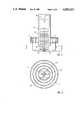
- FIG. 2is a cutaway side view of the septum drive system of FIG. 1.
- FIG. 3is a front view at section A-A of the septum drive system of FIG. 2.
- FIG. 4is a side view of the septum drive wheel employed in the septum drive system of FIG. 3.
- FIG. 5is a front view of the septum drive wheel of FIG. 4.
- FIG. 6is a cutaway side view of another embodiment of the septum drive system of FIG. 1.
- FIG. 7is a front view of the twistable septum system of FIG. 6.
- FIG. 8is a side view of a septum constructed according to the principles of the present invention.
- FIG. 9is a perspective view of another embodiment of the flexible drive rod of the septum drive system of FIG. 1.
- feedhorn 10comprising circular waveguide 11 and corrugated plate 12
- drive motor 13mounted at or near the rear wall on the inside of circular waveguide 11.
- the rotational output of drive motor 13is oriented parallel to and on the circular waveguide and behind the microwave signal output of the feedhorn.
- Aperture cover 14is mounted to corrugated plate 12 employing mounting screws 15. Septum drive wheel 16 is rotatably mounted on the inside surface of aperture cover 14 concentric with the longitudinal axis 7 of circular waveguide 11.
- Septum 20is disposed at the diameter of circular waveguide 11 to receive the desired microwave signal polarization.
- Rotatable leg 21 of septum 20is fixedly coupled to septum drive wheel 16 by keepers 18 formed on one side of septum drive wheel 16.
- One end of drive rod 22fixedly engages septum drive wheel 16 and the other end of drive rod 22 is coupled to the rotational output of drive motor 13. No other support for drive rod 22 is required.
- septum drive wheel 16includes center mounting hole 17 coaxial with the center of the wheel, and off-center hole 19 for receiving one end of drive rod 22.
- the inside diameter of off-center hole 19is slightly less than the outside diameter of drive rod 22, thus providing interference fit of drive rod 22 into off-center hole 19.
- the interference fitassures fixed relationship of septum drive wheel 16 with drive rod 22.
- the fixed relationship of the assembled partsmay be enhanced by providing shoulders in the bore of off-center hole 19 or a polygonal bore for engaging the circular cross section of drive rod 22.
- off-center hole 19need not be a hole if a recess will provide satisfactory fixed relationship of the drive wheel and drive rod assembly.
- drive rod 22When drive motor 13 is energized, torsional rotation is applied to drive rod 22. Since drive rod 22 is fixedly coupled to septum drive wheel 16, it rotates in response to the torsional rotation applied to drive rod 22. Drive rod 22 is flexible along its longitudinal axis 7 so that, as it rotates, it bends to accommodate its off-center coupling with septum drive wheel 16. The distance between center mounting hole 17 and off-center hole 19 determines the radius around which drive rod 22 must flexibly rotate.
- Keepers 18are formed on one side of septum drive wheel 16 for receiving and coupling to rotatable end leg 21 of filament 20 at the diameter of septum drive wheel 16. Keepers 18 each comprise pairs of compression members between which the thinnest dimension of end leg 21 fits. Groove 50 is formed in the rim of drive wheel 16. As septum drive wheel 16 rotates, rotatable end leg 21 is rotated and the remaining interconnected legs of septum 20 incrementally rotate in the same direction. Drive wheel 16 may include noteches as shown in FIG. 5 for use in another embodiment of the present invention described later in this specification.
- feedhorn 10is the same as that described for a feedhorn in the specification mentioned elsewhere and incorporated by reference herein.
- Septum drive motor 13can be the same as, or similar to, servo motors used in remotely controlled model aircraft for control surface movement.
- drive motor 13is mounted on the backside of corrugated plate 12 as shown in FIG. 6.
- Drive rod 60is coupled at one end to the rotational output of drive motor 13 through corrugaged plate 12, and rotatably mounted at the other end to aperture cover 14.
- Pulley wheel 62is coaxially and fixedly mounted at or near the end of drive rod 60,nearest and inside aperture cover 14.
- Pulley wheel 62is coupled to drive wheel 16 by drive belt 64 as shown in FIG. 7.
- Drive belt 64is formed with cross sectional shape suitable for engaging groove 50 of septum drive wheel 16 and includes protrusions for engaging notches 52.
- the dimensions and the configuration of the groove and notches in the rim of pulley wheel 62are identical to the dimensions and the configuration of the groove and notches in the rim of septum drive wheel 16.
- Flexible drive rod 90 shown in FIG. 9eliminates the need for septum drive wheel 16 while still providing axial rotation of the septum.
- Pivot 92is rotatably supported by any support structure such as aperture cover 14 at the aperture concentric with the longitudinal axis of the circular waveguide of the feedhorn.
- Keepers 18, mounted to support bar 93,couple to the rotatable leg 21.
- flexible drive rod 90rotates around pivot 92 which in turn rotates support bar 93 and rotatable end leg 21 around the longitudinal axis 7 of the circular waveguide of the feedhorn.
- the longitudinal axis 7 of drive rod 90 and pivot 92are parallel. They are coupled together by coupling member 94 which, though not required, may be perpendicular to both. Since the longitudinal axis of drive rod 90 is typically fixed at motor end 91, the length of coupling member 94 determines the radius around which drive rod 90 must flexibly rotate.
- Drive rod 90may be a one-piece, molded part including support bar 93 and keepers 18. It should be constructed of material selected for minimal effect on the electrical performance of the feedhorn.
- septum 20is constructed of 0.015 inch thick, type 304 stainless steel flat sheet.
- the interconnected legsare formed by removing the interstitial material from between the legs by conventional stamping processes employing well-known tooling techniques.
- Notches 81are formed in rotatable leg 21 to assure reliable, centered coupling with keepers 18 of septums drive wheel 16.
- Attenuator 84an extension of end leg 86, is rigidly mounted to the inner wall at or near the output end of feedhorn 10 to further attenuate any unwanted polarization transmitted through the feedhorn.
- attenuator 84facilitates mounting of end leg 21 to the wall of circular waveguide 11.
- Aperture cover 14, septum drive wheel 16, drive rod 22, drive rod 60, pulley wheel 62are all molded of plastic material such as polyurethane. Any other, equally lightweight material, having similar electrical characteristics for minimal effect on the electrical performances of the feedhorn, may be used. The material must also be capable of withstanding the environmental extremes of temperature, precipitation and contamination to which feedhorns, used with reflector antennas in earth stations for satellite communications, are exposed.
Landscapes
- Transmission Devices (AREA)
Abstract
Description
Claims (45)
Priority Applications (1)
| Application Number | Priority Date | Filing Date | Title |
|---|---|---|---|
| US06/851,163US4829313A (en) | 1984-11-15 | 1986-04-14 | Drive system and filament for a twistable septum in a feedhorn |
Applications Claiming Priority (2)
| Application Number | Priority Date | Filing Date | Title |
|---|---|---|---|
| US67209484A | 1984-11-15 | 1984-11-15 | |
| US06/851,163US4829313A (en) | 1984-11-15 | 1986-04-14 | Drive system and filament for a twistable septum in a feedhorn |
Related Parent Applications (1)
| Application Number | Title | Priority Date | Filing Date |
|---|---|---|---|
| US67209484AContinuation | 1984-11-15 | 1984-11-15 |
Publications (1)
| Publication Number | Publication Date |
|---|---|
| US4829313Atrue US4829313A (en) | 1989-05-09 |
Family
ID=27100686
Family Applications (1)
| Application Number | Title | Priority Date | Filing Date |
|---|---|---|---|
| US06/851,163Expired - Fee RelatedUS4829313A (en) | 1984-11-15 | 1986-04-14 | Drive system and filament for a twistable septum in a feedhorn |
Country Status (1)
| Country | Link |
|---|---|
| US (1) | US4829313A (en) |
Cited By (103)
| Publication number | Priority date | Publication date | Assignee | Title |
|---|---|---|---|---|
| US4902988A (en)* | 1989-01-27 | 1990-02-20 | Chapparal Communications, Inc. | Control for flexible probe |
| US4951010A (en)* | 1989-03-15 | 1990-08-21 | Maxi Rotor, Inc. | Polarization rotating apparatus for microwave signals |
| US5109232A (en)* | 1990-02-20 | 1992-04-28 | Andrew Corporation | Dual frequency antenna feed with apertured channel |
| US5255003A (en)* | 1987-10-02 | 1993-10-19 | Antenna Downlink, Inc. | Multiple-frequency microwave feed assembly |
| US6297710B1 (en) | 1999-09-02 | 2001-10-02 | Channel Master Llc | Slip joint polarizer |
| US20020171503A1 (en)* | 2001-05-17 | 2002-11-21 | Tetsuyuki Ohtani | Polarized wave separating structure, radio wave receiving converter and antenna apparatus |
| WO2008045350A3 (en)* | 2006-10-06 | 2008-07-17 | Tyco Healthcare | Endoscopic vessel sealer and divider having a flexible articulating shaft |
| US7708735B2 (en) | 2003-05-01 | 2010-05-04 | Covidien Ag | Incorporating rapid cooling in tissue fusion heating processes |
| US7722607B2 (en) | 2005-09-30 | 2010-05-25 | Covidien Ag | In-line vessel sealer and divider |
| US7771425B2 (en) | 2003-06-13 | 2010-08-10 | Covidien Ag | Vessel sealer and divider having a variable jaw clamping mechanism |
| US7776037B2 (en) | 2006-07-07 | 2010-08-17 | Covidien Ag | System and method for controlling electrode gap during tissue sealing |
| US7776036B2 (en) | 2003-03-13 | 2010-08-17 | Covidien Ag | Bipolar concentric electrode assembly for soft tissue fusion |
| US7789878B2 (en) | 2005-09-30 | 2010-09-07 | Covidien Ag | In-line vessel sealer and divider |
| US7799028B2 (en) | 2004-09-21 | 2010-09-21 | Covidien Ag | Articulating bipolar electrosurgical instrument |
| US7799026B2 (en) | 2002-11-14 | 2010-09-21 | Covidien Ag | Compressible jaw configuration with bipolar RF output electrodes for soft tissue fusion |
| US20100249769A1 (en)* | 2009-03-24 | 2010-09-30 | Tyco Healthcare Group Lp | Apparatus for Tissue Sealing |
| US7811283B2 (en) | 2003-11-19 | 2010-10-12 | Covidien Ag | Open vessel sealing instrument with hourglass cutting mechanism and over-ratchet safety |
| US7828798B2 (en) | 1997-11-14 | 2010-11-09 | Covidien Ag | Laparoscopic bipolar electrosurgical instrument |
| US7846161B2 (en) | 2005-09-30 | 2010-12-07 | Covidien Ag | Insulating boot for electrosurgical forceps |
| US7857812B2 (en) | 2003-06-13 | 2010-12-28 | Covidien Ag | Vessel sealer and divider having elongated knife stroke and safety for cutting mechanism |
| US7877852B2 (en) | 2007-09-20 | 2011-02-01 | Tyco Healthcare Group Lp | Method of manufacturing an end effector assembly for sealing tissue |
| US7879035B2 (en) | 2005-09-30 | 2011-02-01 | Covidien Ag | Insulating boot for electrosurgical forceps |
| US7877853B2 (en) | 2007-09-20 | 2011-02-01 | Tyco Healthcare Group Lp | Method of manufacturing end effector assembly for sealing tissue |
| US7887536B2 (en) | 1998-10-23 | 2011-02-15 | Covidien Ag | Vessel sealing instrument |
| US7909823B2 (en) | 2005-01-14 | 2011-03-22 | Covidien Ag | Open vessel sealing instrument |
| US7922718B2 (en) | 2003-11-19 | 2011-04-12 | Covidien Ag | Open vessel sealing instrument with cutting mechanism |
| US7922953B2 (en) | 2005-09-30 | 2011-04-12 | Covidien Ag | Method for manufacturing an end effector assembly |
| US7931649B2 (en) | 2002-10-04 | 2011-04-26 | Tyco Healthcare Group Lp | Vessel sealing instrument with electrical cutting mechanism |
| US7935052B2 (en) | 2004-09-09 | 2011-05-03 | Covidien Ag | Forceps with spring loaded end effector assembly |
| US7947041B2 (en) | 1998-10-23 | 2011-05-24 | Covidien Ag | Vessel sealing instrument |
| US7951150B2 (en) | 2005-01-14 | 2011-05-31 | Covidien Ag | Vessel sealer and divider with rotating sealer and cutter |
| US7955332B2 (en) | 2004-10-08 | 2011-06-07 | Covidien Ag | Mechanism for dividing tissue in a hemostat-style instrument |
| US7963965B2 (en) | 1997-11-12 | 2011-06-21 | Covidien Ag | Bipolar electrosurgical instrument for sealing vessels |
| US8016827B2 (en) | 2008-10-09 | 2011-09-13 | Tyco Healthcare Group Lp | Apparatus, system, and method for performing an electrosurgical procedure |
| USD649249S1 (en) | 2007-02-15 | 2011-11-22 | Tyco Healthcare Group Lp | End effectors of an elongated dissecting and dividing instrument |
| US8070746B2 (en) | 2006-10-03 | 2011-12-06 | Tyco Healthcare Group Lp | Radiofrequency fusion of cardiac tissue |
| US8142473B2 (en) | 2008-10-03 | 2012-03-27 | Tyco Healthcare Group Lp | Method of transferring rotational motion in an articulating surgical instrument |
| US8162940B2 (en) | 2002-10-04 | 2012-04-24 | Covidien Ag | Vessel sealing instrument with electrical cutting mechanism |
| US8162973B2 (en) | 2008-08-15 | 2012-04-24 | Tyco Healthcare Group Lp | Method of transferring pressure in an articulating surgical instrument |
| US8192433B2 (en) | 2002-10-04 | 2012-06-05 | Covidien Ag | Vessel sealing instrument with electrical cutting mechanism |
| US8197479B2 (en) | 2008-12-10 | 2012-06-12 | Tyco Healthcare Group Lp | Vessel sealer and divider |
| US8211105B2 (en) | 1997-11-12 | 2012-07-03 | Covidien Ag | Electrosurgical instrument which reduces collateral damage to adjacent tissue |
| US8221416B2 (en) | 2007-09-28 | 2012-07-17 | Tyco Healthcare Group Lp | Insulating boot for electrosurgical forceps with thermoplastic clevis |
| US8235992B2 (en) | 2007-09-28 | 2012-08-07 | Tyco Healthcare Group Lp | Insulating boot with mechanical reinforcement for electrosurgical forceps |
| US8236025B2 (en) | 2007-09-28 | 2012-08-07 | Tyco Healthcare Group Lp | Silicone insulated electrosurgical forceps |
| US8235993B2 (en) | 2007-09-28 | 2012-08-07 | Tyco Healthcare Group Lp | Insulating boot for electrosurgical forceps with exohinged structure |
| US8241284B2 (en) | 2001-04-06 | 2012-08-14 | Covidien Ag | Vessel sealer and divider with non-conductive stop members |
| US8241283B2 (en) | 2007-09-28 | 2012-08-14 | Tyco Healthcare Group Lp | Dual durometer insulating boot for electrosurgical forceps |
| US8241282B2 (en) | 2006-01-24 | 2012-08-14 | Tyco Healthcare Group Lp | Vessel sealing cutting assemblies |
| US8251996B2 (en) | 2007-09-28 | 2012-08-28 | Tyco Healthcare Group Lp | Insulating sheath for electrosurgical forceps |
| US8257387B2 (en) | 2008-08-15 | 2012-09-04 | Tyco Healthcare Group Lp | Method of transferring pressure in an articulating surgical instrument |
| US8257352B2 (en) | 2003-11-17 | 2012-09-04 | Covidien Ag | Bipolar forceps having monopolar extension |
| US8267936B2 (en) | 2007-09-28 | 2012-09-18 | Tyco Healthcare Group Lp | Insulating mechanically-interfaced adhesive for electrosurgical forceps |
| US8267935B2 (en) | 2007-04-04 | 2012-09-18 | Tyco Healthcare Group Lp | Electrosurgical instrument reducing current densities at an insulator conductor junction |
| US8298228B2 (en) | 1997-11-12 | 2012-10-30 | Coviden Ag | Electrosurgical instrument which reduces collateral damage to adjacent tissue |
| US8298232B2 (en) | 2006-01-24 | 2012-10-30 | Tyco Healthcare Group Lp | Endoscopic vessel sealer and divider for large tissue structures |
| US8303586B2 (en) | 2003-11-19 | 2012-11-06 | Covidien Ag | Spring loaded reciprocating tissue cutting mechanism in a forceps-style electrosurgical instrument |
| US8303582B2 (en) | 2008-09-15 | 2012-11-06 | Tyco Healthcare Group Lp | Electrosurgical instrument having a coated electrode utilizing an atomic layer deposition technique |
| US8317787B2 (en) | 2008-08-28 | 2012-11-27 | Covidien Lp | Tissue fusion jaw angle improvement |
| US8348948B2 (en) | 2004-03-02 | 2013-01-08 | Covidien Ag | Vessel sealing system using capacitive RF dielectric heating |
| US8361071B2 (en) | 1999-10-22 | 2013-01-29 | Covidien Ag | Vessel sealing forceps with disposable electrodes |
| US8382754B2 (en) | 2005-03-31 | 2013-02-26 | Covidien Ag | Electrosurgical forceps with slow closure sealing plates and method of sealing tissue |
| USD680220S1 (en) | 2012-01-12 | 2013-04-16 | Coviden IP | Slider handle for laparoscopic device |
| US8454602B2 (en) | 2009-05-07 | 2013-06-04 | Covidien Lp | Apparatus, system, and method for performing an electrosurgical procedure |
| US8469957B2 (en) | 2008-10-07 | 2013-06-25 | Covidien Lp | Apparatus, system, and method for performing an electrosurgical procedure |
| US8469956B2 (en) | 2008-07-21 | 2013-06-25 | Covidien Lp | Variable resistor jaw |
| US8475453B2 (en) | 2006-10-06 | 2013-07-02 | Covidien Lp | Endoscopic vessel sealer and divider having a flexible articulating shaft |
| US8486107B2 (en) | 2008-10-20 | 2013-07-16 | Covidien Lp | Method of sealing tissue using radiofrequency energy |
| US8491625B2 (en) | 2010-06-02 | 2013-07-23 | Covidien Lp | Apparatus for performing an electrosurgical procedure |
| US8496656B2 (en) | 2003-05-15 | 2013-07-30 | Covidien Ag | Tissue sealer with non-conductive variable stop members and method of sealing tissue |
| US8523898B2 (en) | 2009-07-08 | 2013-09-03 | Covidien Lp | Endoscopic electrosurgical jaws with offset knife |
| US8535312B2 (en) | 2008-09-25 | 2013-09-17 | Covidien Lp | Apparatus, system and method for performing an electrosurgical procedure |
| US8591506B2 (en) | 1998-10-23 | 2013-11-26 | Covidien Ag | Vessel sealing system |
| US8597297B2 (en) | 2006-08-29 | 2013-12-03 | Covidien Ag | Vessel sealing instrument with multiple electrode configurations |
| US8623276B2 (en) | 2008-02-15 | 2014-01-07 | Covidien Lp | Method and system for sterilizing an electrosurgical instrument |
| US8636761B2 (en) | 2008-10-09 | 2014-01-28 | Covidien Lp | Apparatus, system, and method for performing an endoscopic electrosurgical procedure |
| US8641713B2 (en) | 2005-09-30 | 2014-02-04 | Covidien Ag | Flexible endoscopic catheter with ligasure |
| US8647341B2 (en) | 2003-06-13 | 2014-02-11 | Covidien Ag | Vessel sealer and divider for use with small trocars and cannulas |
| US8734443B2 (en) | 2006-01-24 | 2014-05-27 | Covidien Lp | Vessel sealer and divider for large tissue structures |
| US8764748B2 (en) | 2008-02-06 | 2014-07-01 | Covidien Lp | End effector assembly for electrosurgical device and method for making the same |
| US8784417B2 (en) | 2008-08-28 | 2014-07-22 | Covidien Lp | Tissue fusion jaw angle improvement |
| US8795274B2 (en) | 2008-08-28 | 2014-08-05 | Covidien Lp | Tissue fusion jaw angle improvement |
| US8852228B2 (en) | 2009-01-13 | 2014-10-07 | Covidien Lp | Apparatus, system, and method for performing an electrosurgical procedure |
| US8882766B2 (en) | 2006-01-24 | 2014-11-11 | Covidien Ag | Method and system for controlling delivery of energy to divide tissue |
| US8898888B2 (en) | 2009-09-28 | 2014-12-02 | Covidien Lp | System for manufacturing electrosurgical seal plates |
| US8968314B2 (en) | 2008-09-25 | 2015-03-03 | Covidien Lp | Apparatus, system and method for performing an electrosurgical procedure |
| CN104577326A (en)* | 2013-10-09 | 2015-04-29 | 启碁科技股份有限公司 | Feed-in device and wave collector |
| US9023043B2 (en) | 2007-09-28 | 2015-05-05 | Covidien Lp | Insulating mechanically-interfaced boot and jaws for electrosurgical forceps |
| US9028493B2 (en) | 2009-09-18 | 2015-05-12 | Covidien Lp | In vivo attachable and detachable end effector assembly and laparoscopic surgical instrument and methods therefor |
| US9095347B2 (en) | 2003-11-20 | 2015-08-04 | Covidien Ag | Electrically conductive/insulative over shoe for tissue fusion |
| US9107672B2 (en) | 1998-10-23 | 2015-08-18 | Covidien Ag | Vessel sealing forceps with disposable electrodes |
| US9113940B2 (en) | 2011-01-14 | 2015-08-25 | Covidien Lp | Trigger lockout and kickback mechanism for surgical instruments |
| US9149323B2 (en) | 2003-05-01 | 2015-10-06 | Covidien Ag | Method of fusing biomaterials with radiofrequency energy |
| US9214711B2 (en) | 2013-03-11 | 2015-12-15 | Commscope Technologies Llc | Twist septum polarization rotator |
| US9375254B2 (en) | 2008-09-25 | 2016-06-28 | Covidien Lp | Seal and separate algorithm |
| US9603652B2 (en) | 2008-08-21 | 2017-03-28 | Covidien Lp | Electrosurgical instrument including a sensor |
| US9848938B2 (en) | 2003-11-13 | 2017-12-26 | Covidien Ag | Compressible jaw configuration with bipolar RF output electrodes for soft tissue fusion |
| US10213250B2 (en) | 2015-11-05 | 2019-02-26 | Covidien Lp | Deployment and safety mechanisms for surgical instruments |
| US10231777B2 (en) | 2014-08-26 | 2019-03-19 | Covidien Lp | Methods of manufacturing jaw members of an end-effector assembly for a surgical instrument |
| US10646267B2 (en) | 2013-08-07 | 2020-05-12 | Covidien LLP | Surgical forceps |
| US10987159B2 (en) | 2015-08-26 | 2021-04-27 | Covidien Lp | Electrosurgical end effector assemblies and electrosurgical forceps configured to reduce thermal spread |
| US11166759B2 (en) | 2017-05-16 | 2021-11-09 | Covidien Lp | Surgical forceps |
| USD956973S1 (en) | 2003-06-13 | 2022-07-05 | Covidien Ag | Movable handle for endoscopic vessel sealer and divider |
Citations (10)
| Publication number | Priority date | Publication date | Assignee | Title |
|---|---|---|---|---|
| US2429601A (en)* | 1943-11-22 | 1947-10-28 | Bell Telephone Labor Inc | Microwave radar directive antenna |
| US2541030A (en)* | 1941-10-30 | 1951-02-13 | Standard Telephones Cables Ltd | Radio pulse distance and direction indicator |
| US2628278A (en)* | 1951-09-20 | 1953-02-10 | Gen Precision Lab Inc | Apparatus for rotating microwave energy |
| GB804200A (en)* | 1954-12-31 | 1958-11-12 | Sperry Rand Corp | Microwave transmission systems |
| US2987722A (en)* | 1947-12-29 | 1961-06-06 | Bell Telephone Labor Inc | Scanning mechanism for radio signaling apparatus |
| US3296558A (en)* | 1965-09-22 | 1967-01-03 | Canadian Patents Dev | Polarization converter comprising metal rods mounted on a torsion wire that twists when rotated |
| US3307183A (en)* | 1957-03-11 | 1967-02-28 | Boeing Co | Conical scan radar system and antenna |
| US4503379A (en)* | 1983-04-12 | 1985-03-05 | Chaparral Communications, Inc. | Rotation of microwave signal polarization using a twistable, serpentine-shaped filament |
| US4504836A (en)* | 1982-06-01 | 1985-03-12 | Seavey Engineering Associates, Inc. | Antenna feeding with selectively controlled polarization |
| US4574258A (en)* | 1984-08-27 | 1986-03-04 | M/A-Com, Inc. | Polarized signal receiving apparatus |
- 1986
- 1986-04-14USUS06/851,163patent/US4829313A/ennot_activeExpired - Fee Related
Patent Citations (10)
| Publication number | Priority date | Publication date | Assignee | Title |
|---|---|---|---|---|
| US2541030A (en)* | 1941-10-30 | 1951-02-13 | Standard Telephones Cables Ltd | Radio pulse distance and direction indicator |
| US2429601A (en)* | 1943-11-22 | 1947-10-28 | Bell Telephone Labor Inc | Microwave radar directive antenna |
| US2987722A (en)* | 1947-12-29 | 1961-06-06 | Bell Telephone Labor Inc | Scanning mechanism for radio signaling apparatus |
| US2628278A (en)* | 1951-09-20 | 1953-02-10 | Gen Precision Lab Inc | Apparatus for rotating microwave energy |
| GB804200A (en)* | 1954-12-31 | 1958-11-12 | Sperry Rand Corp | Microwave transmission systems |
| US3307183A (en)* | 1957-03-11 | 1967-02-28 | Boeing Co | Conical scan radar system and antenna |
| US3296558A (en)* | 1965-09-22 | 1967-01-03 | Canadian Patents Dev | Polarization converter comprising metal rods mounted on a torsion wire that twists when rotated |
| US4504836A (en)* | 1982-06-01 | 1985-03-12 | Seavey Engineering Associates, Inc. | Antenna feeding with selectively controlled polarization |
| US4503379A (en)* | 1983-04-12 | 1985-03-05 | Chaparral Communications, Inc. | Rotation of microwave signal polarization using a twistable, serpentine-shaped filament |
| US4574258A (en)* | 1984-08-27 | 1986-03-04 | M/A-Com, Inc. | Polarized signal receiving apparatus |
Cited By (164)
| Publication number | Priority date | Publication date | Assignee | Title |
|---|---|---|---|---|
| US5255003A (en)* | 1987-10-02 | 1993-10-19 | Antenna Downlink, Inc. | Multiple-frequency microwave feed assembly |
| US4902988A (en)* | 1989-01-27 | 1990-02-20 | Chapparal Communications, Inc. | Control for flexible probe |
| US4951010A (en)* | 1989-03-15 | 1990-08-21 | Maxi Rotor, Inc. | Polarization rotating apparatus for microwave signals |
| US5109232A (en)* | 1990-02-20 | 1992-04-28 | Andrew Corporation | Dual frequency antenna feed with apertured channel |
| US7963965B2 (en) | 1997-11-12 | 2011-06-21 | Covidien Ag | Bipolar electrosurgical instrument for sealing vessels |
| US8211105B2 (en) | 1997-11-12 | 2012-07-03 | Covidien Ag | Electrosurgical instrument which reduces collateral damage to adjacent tissue |
| US8298228B2 (en) | 1997-11-12 | 2012-10-30 | Coviden Ag | Electrosurgical instrument which reduces collateral damage to adjacent tissue |
| US7828798B2 (en) | 1997-11-14 | 2010-11-09 | Covidien Ag | Laparoscopic bipolar electrosurgical instrument |
| US9107672B2 (en) | 1998-10-23 | 2015-08-18 | Covidien Ag | Vessel sealing forceps with disposable electrodes |
| US7887536B2 (en) | 1998-10-23 | 2011-02-15 | Covidien Ag | Vessel sealing instrument |
| US9375270B2 (en) | 1998-10-23 | 2016-06-28 | Covidien Ag | Vessel sealing system |
| US8591506B2 (en) | 1998-10-23 | 2013-11-26 | Covidien Ag | Vessel sealing system |
| US9375271B2 (en) | 1998-10-23 | 2016-06-28 | Covidien Ag | Vessel sealing system |
| US9463067B2 (en) | 1998-10-23 | 2016-10-11 | Covidien Ag | Vessel sealing system |
| US7947041B2 (en) | 1998-10-23 | 2011-05-24 | Covidien Ag | Vessel sealing instrument |
| US7896878B2 (en) | 1998-10-23 | 2011-03-01 | Coviden Ag | Vessel sealing instrument |
| US6297710B1 (en) | 1999-09-02 | 2001-10-02 | Channel Master Llc | Slip joint polarizer |
| US8361071B2 (en) | 1999-10-22 | 2013-01-29 | Covidien Ag | Vessel sealing forceps with disposable electrodes |
| US10265121B2 (en) | 2001-04-06 | 2019-04-23 | Covidien Ag | Vessel sealer and divider |
| US10251696B2 (en) | 2001-04-06 | 2019-04-09 | Covidien Ag | Vessel sealer and divider with stop members |
| US8241284B2 (en) | 2001-04-06 | 2012-08-14 | Covidien Ag | Vessel sealer and divider with non-conductive stop members |
| US10687887B2 (en) | 2001-04-06 | 2020-06-23 | Covidien Ag | Vessel sealer and divider |
| US6859184B2 (en)* | 2001-05-17 | 2005-02-22 | Sharp Kabushiki Kaisha | Polarized wave separating structure, radio wave receiving converter and antenna apparatus |
| US20020171503A1 (en)* | 2001-05-17 | 2002-11-21 | Tetsuyuki Ohtani | Polarized wave separating structure, radio wave receiving converter and antenna apparatus |
| US8333765B2 (en) | 2002-10-04 | 2012-12-18 | Covidien Ag | Vessel sealing instrument with electrical cutting mechanism |
| US8162940B2 (en) | 2002-10-04 | 2012-04-24 | Covidien Ag | Vessel sealing instrument with electrical cutting mechanism |
| US9585716B2 (en) | 2002-10-04 | 2017-03-07 | Covidien Ag | Vessel sealing instrument with electrical cutting mechanism |
| US8192433B2 (en) | 2002-10-04 | 2012-06-05 | Covidien Ag | Vessel sealing instrument with electrical cutting mechanism |
| US10537384B2 (en) | 2002-10-04 | 2020-01-21 | Covidien Lp | Vessel sealing instrument with electrical cutting mechanism |
| US10987160B2 (en) | 2002-10-04 | 2021-04-27 | Covidien Ag | Vessel sealing instrument with cutting mechanism |
| US8551091B2 (en) | 2002-10-04 | 2013-10-08 | Covidien Ag | Vessel sealing instrument with electrical cutting mechanism |
| US7931649B2 (en) | 2002-10-04 | 2011-04-26 | Tyco Healthcare Group Lp | Vessel sealing instrument with electrical cutting mechanism |
| US8740901B2 (en) | 2002-10-04 | 2014-06-03 | Covidien Ag | Vessel sealing instrument with electrical cutting mechanism |
| US8945125B2 (en) | 2002-11-14 | 2015-02-03 | Covidien Ag | Compressible jaw configuration with bipolar RF output electrodes for soft tissue fusion |
| US7799026B2 (en) | 2002-11-14 | 2010-09-21 | Covidien Ag | Compressible jaw configuration with bipolar RF output electrodes for soft tissue fusion |
| US7776036B2 (en) | 2003-03-13 | 2010-08-17 | Covidien Ag | Bipolar concentric electrode assembly for soft tissue fusion |
| US8679114B2 (en) | 2003-05-01 | 2014-03-25 | Covidien Ag | Incorporating rapid cooling in tissue fusion heating processes |
| US9149323B2 (en) | 2003-05-01 | 2015-10-06 | Covidien Ag | Method of fusing biomaterials with radiofrequency energy |
| US7708735B2 (en) | 2003-05-01 | 2010-05-04 | Covidien Ag | Incorporating rapid cooling in tissue fusion heating processes |
| US8496656B2 (en) | 2003-05-15 | 2013-07-30 | Covidien Ag | Tissue sealer with non-conductive variable stop members and method of sealing tissue |
| USRE47375E1 (en) | 2003-05-15 | 2019-05-07 | Coviden Ag | Tissue sealer with non-conductive variable stop members and method of sealing tissue |
| US10918435B2 (en) | 2003-06-13 | 2021-02-16 | Covidien Ag | Vessel sealer and divider |
| US10278772B2 (en) | 2003-06-13 | 2019-05-07 | Covidien Ag | Vessel sealer and divider |
| US10842553B2 (en) | 2003-06-13 | 2020-11-24 | Covidien Ag | Vessel sealer and divider |
| US7771425B2 (en) | 2003-06-13 | 2010-08-10 | Covidien Ag | Vessel sealer and divider having a variable jaw clamping mechanism |
| USD956973S1 (en) | 2003-06-13 | 2022-07-05 | Covidien Ag | Movable handle for endoscopic vessel sealer and divider |
| US7857812B2 (en) | 2003-06-13 | 2010-12-28 | Covidien Ag | Vessel sealer and divider having elongated knife stroke and safety for cutting mechanism |
| US9492225B2 (en) | 2003-06-13 | 2016-11-15 | Covidien Ag | Vessel sealer and divider for use with small trocars and cannulas |
| US8647341B2 (en) | 2003-06-13 | 2014-02-11 | Covidien Ag | Vessel sealer and divider for use with small trocars and cannulas |
| US9848938B2 (en) | 2003-11-13 | 2017-12-26 | Covidien Ag | Compressible jaw configuration with bipolar RF output electrodes for soft tissue fusion |
| US8257352B2 (en) | 2003-11-17 | 2012-09-04 | Covidien Ag | Bipolar forceps having monopolar extension |
| US8597296B2 (en) | 2003-11-17 | 2013-12-03 | Covidien Ag | Bipolar forceps having monopolar extension |
| US10441350B2 (en) | 2003-11-17 | 2019-10-15 | Covidien Ag | Bipolar forceps having monopolar extension |
| US8623017B2 (en) | 2003-11-19 | 2014-01-07 | Covidien Ag | Open vessel sealing instrument with hourglass cutting mechanism and overratchet safety |
| US7811283B2 (en) | 2003-11-19 | 2010-10-12 | Covidien Ag | Open vessel sealing instrument with hourglass cutting mechanism and over-ratchet safety |
| US7922718B2 (en) | 2003-11-19 | 2011-04-12 | Covidien Ag | Open vessel sealing instrument with cutting mechanism |
| US8394096B2 (en) | 2003-11-19 | 2013-03-12 | Covidien Ag | Open vessel sealing instrument with cutting mechanism |
| US8303586B2 (en) | 2003-11-19 | 2012-11-06 | Covidien Ag | Spring loaded reciprocating tissue cutting mechanism in a forceps-style electrosurgical instrument |
| US9980770B2 (en) | 2003-11-20 | 2018-05-29 | Covidien Ag | Electrically conductive/insulative over-shoe for tissue fusion |
| US9095347B2 (en) | 2003-11-20 | 2015-08-04 | Covidien Ag | Electrically conductive/insulative over shoe for tissue fusion |
| US8348948B2 (en) | 2004-03-02 | 2013-01-08 | Covidien Ag | Vessel sealing system using capacitive RF dielectric heating |
| US7935052B2 (en) | 2004-09-09 | 2011-05-03 | Covidien Ag | Forceps with spring loaded end effector assembly |
| US8366709B2 (en) | 2004-09-21 | 2013-02-05 | Covidien Ag | Articulating bipolar electrosurgical instrument |
| US7799028B2 (en) | 2004-09-21 | 2010-09-21 | Covidien Ag | Articulating bipolar electrosurgical instrument |
| US7955332B2 (en) | 2004-10-08 | 2011-06-07 | Covidien Ag | Mechanism for dividing tissue in a hemostat-style instrument |
| US8123743B2 (en) | 2004-10-08 | 2012-02-28 | Covidien Ag | Mechanism for dividing tissue in a hemostat-style instrument |
| US20110196368A1 (en)* | 2005-01-14 | 2011-08-11 | Covidien Ag | Open Vessel Sealing Instrument |
| US8147489B2 (en) | 2005-01-14 | 2012-04-03 | Covidien Ag | Open vessel sealing instrument |
| US7951150B2 (en) | 2005-01-14 | 2011-05-31 | Covidien Ag | Vessel sealer and divider with rotating sealer and cutter |
| US7909823B2 (en) | 2005-01-14 | 2011-03-22 | Covidien Ag | Open vessel sealing instrument |
| US8382754B2 (en) | 2005-03-31 | 2013-02-26 | Covidien Ag | Electrosurgical forceps with slow closure sealing plates and method of sealing tissue |
| US9549775B2 (en) | 2005-09-30 | 2017-01-24 | Covidien Ag | In-line vessel sealer and divider |
| USRE44834E1 (en) | 2005-09-30 | 2014-04-08 | Covidien Ag | Insulating boot for electrosurgical forceps |
| US7879035B2 (en) | 2005-09-30 | 2011-02-01 | Covidien Ag | Insulating boot for electrosurgical forceps |
| US8394095B2 (en) | 2005-09-30 | 2013-03-12 | Covidien Ag | Insulating boot for electrosurgical forceps |
| US7722607B2 (en) | 2005-09-30 | 2010-05-25 | Covidien Ag | In-line vessel sealer and divider |
| US9579145B2 (en) | 2005-09-30 | 2017-02-28 | Covidien Ag | Flexible endoscopic catheter with ligasure |
| US8197633B2 (en) | 2005-09-30 | 2012-06-12 | Covidien Ag | Method for manufacturing an end effector assembly |
| US8668689B2 (en) | 2005-09-30 | 2014-03-11 | Covidien Ag | In-line vessel sealer and divider |
| US7789878B2 (en) | 2005-09-30 | 2010-09-07 | Covidien Ag | In-line vessel sealer and divider |
| US8361072B2 (en) | 2005-09-30 | 2013-01-29 | Covidien Ag | Insulating boot for electrosurgical forceps |
| US8641713B2 (en) | 2005-09-30 | 2014-02-04 | Covidien Ag | Flexible endoscopic catheter with ligasure |
| US7846161B2 (en) | 2005-09-30 | 2010-12-07 | Covidien Ag | Insulating boot for electrosurgical forceps |
| US7922953B2 (en) | 2005-09-30 | 2011-04-12 | Covidien Ag | Method for manufacturing an end effector assembly |
| US8882766B2 (en) | 2006-01-24 | 2014-11-11 | Covidien Ag | Method and system for controlling delivery of energy to divide tissue |
| US8734443B2 (en) | 2006-01-24 | 2014-05-27 | Covidien Lp | Vessel sealer and divider for large tissue structures |
| US9539053B2 (en) | 2006-01-24 | 2017-01-10 | Covidien Lp | Vessel sealer and divider for large tissue structures |
| US8241282B2 (en) | 2006-01-24 | 2012-08-14 | Tyco Healthcare Group Lp | Vessel sealing cutting assemblies |
| US9113903B2 (en) | 2006-01-24 | 2015-08-25 | Covidien Lp | Endoscopic vessel sealer and divider for large tissue structures |
| US8298232B2 (en) | 2006-01-24 | 2012-10-30 | Tyco Healthcare Group Lp | Endoscopic vessel sealer and divider for large tissue structures |
| US9918782B2 (en) | 2006-01-24 | 2018-03-20 | Covidien Lp | Endoscopic vessel sealer and divider for large tissue structures |
| US7776037B2 (en) | 2006-07-07 | 2010-08-17 | Covidien Ag | System and method for controlling electrode gap during tissue sealing |
| US8597297B2 (en) | 2006-08-29 | 2013-12-03 | Covidien Ag | Vessel sealing instrument with multiple electrode configurations |
| US8425504B2 (en) | 2006-10-03 | 2013-04-23 | Covidien Lp | Radiofrequency fusion of cardiac tissue |
| US8070746B2 (en) | 2006-10-03 | 2011-12-06 | Tyco Healthcare Group Lp | Radiofrequency fusion of cardiac tissue |
| US9204924B2 (en) | 2006-10-06 | 2015-12-08 | Covidien Lp | Endoscopic vessel sealer and divider having a flexible articulating shaft |
| WO2008045350A3 (en)* | 2006-10-06 | 2008-07-17 | Tyco Healthcare | Endoscopic vessel sealer and divider having a flexible articulating shaft |
| US20100076433A1 (en)* | 2006-10-06 | 2010-03-25 | Eric Taylor | Endoscopic Vessel Sealer and Divider Having a Flexible Articulating Shaft |
| US9968397B2 (en)* | 2006-10-06 | 2018-05-15 | Covidien Lp | Endoscopic vessel sealer and divider having a flexible articulating shaft |
| US8721640B2 (en) | 2006-10-06 | 2014-05-13 | Covidien Lp | Endoscopic vessel sealer and divider having a flexible articulating shaft |
| US20100094289A1 (en)* | 2006-10-06 | 2010-04-15 | Taylor Eric J | Endoscopic Vessel Sealer and Divider Having a Flexible Articulating Shaft |
| US8475453B2 (en) | 2006-10-06 | 2013-07-02 | Covidien Lp | Endoscopic vessel sealer and divider having a flexible articulating shaft |
| CN101522128B (en)* | 2006-10-06 | 2012-02-15 | Tyco医疗健康集团 | Endoscopic vessel sealer and divider having a flexible articulating shaft |
| USD649249S1 (en) | 2007-02-15 | 2011-11-22 | Tyco Healthcare Group Lp | End effectors of an elongated dissecting and dividing instrument |
| US8267935B2 (en) | 2007-04-04 | 2012-09-18 | Tyco Healthcare Group Lp | Electrosurgical instrument reducing current densities at an insulator conductor junction |
| US7877853B2 (en) | 2007-09-20 | 2011-02-01 | Tyco Healthcare Group Lp | Method of manufacturing end effector assembly for sealing tissue |
| US7877852B2 (en) | 2007-09-20 | 2011-02-01 | Tyco Healthcare Group Lp | Method of manufacturing an end effector assembly for sealing tissue |
| US9554841B2 (en) | 2007-09-28 | 2017-01-31 | Covidien Lp | Dual durometer insulating boot for electrosurgical forceps |
| US8236025B2 (en) | 2007-09-28 | 2012-08-07 | Tyco Healthcare Group Lp | Silicone insulated electrosurgical forceps |
| US8251996B2 (en) | 2007-09-28 | 2012-08-28 | Tyco Healthcare Group Lp | Insulating sheath for electrosurgical forceps |
| US8241283B2 (en) | 2007-09-28 | 2012-08-14 | Tyco Healthcare Group Lp | Dual durometer insulating boot for electrosurgical forceps |
| US8267936B2 (en) | 2007-09-28 | 2012-09-18 | Tyco Healthcare Group Lp | Insulating mechanically-interfaced adhesive for electrosurgical forceps |
| US8696667B2 (en) | 2007-09-28 | 2014-04-15 | Covidien Lp | Dual durometer insulating boot for electrosurgical forceps |
| US8221416B2 (en) | 2007-09-28 | 2012-07-17 | Tyco Healthcare Group Lp | Insulating boot for electrosurgical forceps with thermoplastic clevis |
| US9023043B2 (en) | 2007-09-28 | 2015-05-05 | Covidien Lp | Insulating mechanically-interfaced boot and jaws for electrosurgical forceps |
| US8235992B2 (en) | 2007-09-28 | 2012-08-07 | Tyco Healthcare Group Lp | Insulating boot with mechanical reinforcement for electrosurgical forceps |
| US8235993B2 (en) | 2007-09-28 | 2012-08-07 | Tyco Healthcare Group Lp | Insulating boot for electrosurgical forceps with exohinged structure |
| US8764748B2 (en) | 2008-02-06 | 2014-07-01 | Covidien Lp | End effector assembly for electrosurgical device and method for making the same |
| US8623276B2 (en) | 2008-02-15 | 2014-01-07 | Covidien Lp | Method and system for sterilizing an electrosurgical instrument |
| US8469956B2 (en) | 2008-07-21 | 2013-06-25 | Covidien Lp | Variable resistor jaw |
| US9113905B2 (en) | 2008-07-21 | 2015-08-25 | Covidien Lp | Variable resistor jaw |
| US9247988B2 (en) | 2008-07-21 | 2016-02-02 | Covidien Lp | Variable resistor jaw |
| US8162973B2 (en) | 2008-08-15 | 2012-04-24 | Tyco Healthcare Group Lp | Method of transferring pressure in an articulating surgical instrument |
| US8257387B2 (en) | 2008-08-15 | 2012-09-04 | Tyco Healthcare Group Lp | Method of transferring pressure in an articulating surgical instrument |
| US9603652B2 (en) | 2008-08-21 | 2017-03-28 | Covidien Lp | Electrosurgical instrument including a sensor |
| US8795274B2 (en) | 2008-08-28 | 2014-08-05 | Covidien Lp | Tissue fusion jaw angle improvement |
| US8317787B2 (en) | 2008-08-28 | 2012-11-27 | Covidien Lp | Tissue fusion jaw angle improvement |
| US8784417B2 (en) | 2008-08-28 | 2014-07-22 | Covidien Lp | Tissue fusion jaw angle improvement |
| US8303582B2 (en) | 2008-09-15 | 2012-11-06 | Tyco Healthcare Group Lp | Electrosurgical instrument having a coated electrode utilizing an atomic layer deposition technique |
| US8968314B2 (en) | 2008-09-25 | 2015-03-03 | Covidien Lp | Apparatus, system and method for performing an electrosurgical procedure |
| US8535312B2 (en) | 2008-09-25 | 2013-09-17 | Covidien Lp | Apparatus, system and method for performing an electrosurgical procedure |
| US9375254B2 (en) | 2008-09-25 | 2016-06-28 | Covidien Lp | Seal and separate algorithm |
| US8142473B2 (en) | 2008-10-03 | 2012-03-27 | Tyco Healthcare Group Lp | Method of transferring rotational motion in an articulating surgical instrument |
| US8568444B2 (en) | 2008-10-03 | 2013-10-29 | Covidien Lp | Method of transferring rotational motion in an articulating surgical instrument |
| US8469957B2 (en) | 2008-10-07 | 2013-06-25 | Covidien Lp | Apparatus, system, and method for performing an electrosurgical procedure |
| US8636761B2 (en) | 2008-10-09 | 2014-01-28 | Covidien Lp | Apparatus, system, and method for performing an endoscopic electrosurgical procedure |
| US8016827B2 (en) | 2008-10-09 | 2011-09-13 | Tyco Healthcare Group Lp | Apparatus, system, and method for performing an electrosurgical procedure |
| US9113898B2 (en) | 2008-10-09 | 2015-08-25 | Covidien Lp | Apparatus, system, and method for performing an electrosurgical procedure |
| US8486107B2 (en) | 2008-10-20 | 2013-07-16 | Covidien Lp | Method of sealing tissue using radiofrequency energy |
| US8197479B2 (en) | 2008-12-10 | 2012-06-12 | Tyco Healthcare Group Lp | Vessel sealer and divider |
| US9655674B2 (en) | 2009-01-13 | 2017-05-23 | Covidien Lp | Apparatus, system and method for performing an electrosurgical procedure |
| US8852228B2 (en) | 2009-01-13 | 2014-10-07 | Covidien Lp | Apparatus, system, and method for performing an electrosurgical procedure |
| US20100249769A1 (en)* | 2009-03-24 | 2010-09-30 | Tyco Healthcare Group Lp | Apparatus for Tissue Sealing |
| US8858554B2 (en) | 2009-05-07 | 2014-10-14 | Covidien Lp | Apparatus, system, and method for performing an electrosurgical procedure |
| US10085794B2 (en) | 2009-05-07 | 2018-10-02 | Covidien Lp | Apparatus, system and method for performing an electrosurgical procedure |
| US8454602B2 (en) | 2009-05-07 | 2013-06-04 | Covidien Lp | Apparatus, system, and method for performing an electrosurgical procedure |
| US9345535B2 (en) | 2009-05-07 | 2016-05-24 | Covidien Lp | Apparatus, system and method for performing an electrosurgical procedure |
| US8523898B2 (en) | 2009-07-08 | 2013-09-03 | Covidien Lp | Endoscopic electrosurgical jaws with offset knife |
| US9931131B2 (en) | 2009-09-18 | 2018-04-03 | Covidien Lp | In vivo attachable and detachable end effector assembly and laparoscopic surgical instrument and methods therefor |
| US9028493B2 (en) | 2009-09-18 | 2015-05-12 | Covidien Lp | In vivo attachable and detachable end effector assembly and laparoscopic surgical instrument and methods therefor |
| US8898888B2 (en) | 2009-09-28 | 2014-12-02 | Covidien Lp | System for manufacturing electrosurgical seal plates |
| US8491625B2 (en) | 2010-06-02 | 2013-07-23 | Covidien Lp | Apparatus for performing an electrosurgical procedure |
| US10383649B2 (en) | 2011-01-14 | 2019-08-20 | Covidien Lp | Trigger lockout and kickback mechanism for surgical instruments |
| US9113940B2 (en) | 2011-01-14 | 2015-08-25 | Covidien Lp | Trigger lockout and kickback mechanism for surgical instruments |
| US11660108B2 (en) | 2011-01-14 | 2023-05-30 | Covidien Lp | Trigger lockout and kickback mechanism for surgical instruments |
| USD680220S1 (en) | 2012-01-12 | 2013-04-16 | Coviden IP | Slider handle for laparoscopic device |
| US9214711B2 (en) | 2013-03-11 | 2015-12-15 | Commscope Technologies Llc | Twist septum polarization rotator |
| US10646267B2 (en) | 2013-08-07 | 2020-05-12 | Covidien LLP | Surgical forceps |
| CN104577326B (en)* | 2013-10-09 | 2017-05-10 | 启碁科技股份有限公司 | Feed-in device and wave collector |
| CN104577326A (en)* | 2013-10-09 | 2015-04-29 | 启碁科技股份有限公司 | Feed-in device and wave collector |
| US10231777B2 (en) | 2014-08-26 | 2019-03-19 | Covidien Lp | Methods of manufacturing jaw members of an end-effector assembly for a surgical instrument |
| US10987159B2 (en) | 2015-08-26 | 2021-04-27 | Covidien Lp | Electrosurgical end effector assemblies and electrosurgical forceps configured to reduce thermal spread |
| US10213250B2 (en) | 2015-11-05 | 2019-02-26 | Covidien Lp | Deployment and safety mechanisms for surgical instruments |
| US11166759B2 (en) | 2017-05-16 | 2021-11-09 | Covidien Lp | Surgical forceps |
Similar Documents
| Publication | Publication Date | Title |
|---|---|---|
| US4829313A (en) | Drive system and filament for a twistable septum in a feedhorn | |
| US6987487B2 (en) | Antenna system | |
| US4353185A (en) | Window raiser | |
| US6034643A (en) | Directional beam antenna device and directional beam controlling apparatus | |
| US4528528A (en) | Waveguide polarization coupling | |
| JPS60136618A (en) | Car steering sub-assembly | |
| CA1249366A (en) | Drive system and filament for a twistable septum in a feedhorn | |
| JPH0532921B2 (en) | ||
| EP0199417B1 (en) | Flexible-element transmission unit for driving rotary members | |
| US4866456A (en) | Horizon-to-horizon satellite antenna drive mechanism | |
| US3568208A (en) | Varying propagation constant waveguide | |
| CA1208720A (en) | Method and apparatus for rotation of microwave signal polarization | |
| US5389940A (en) | Antenna pointing mechanism | |
| CA1210230A (en) | Shaving apparatus | |
| EP1093201B1 (en) | Cable reel and electromagnetic wave communication device equipped with such a reel | |
| DE69421009T2 (en) | Antenna connection with individual transmit and receive antenna elements for different frequencies | |
| US4080049A (en) | Apparatus for adjusting a mirror around two mutually perpendicular axes | |
| GB2215138A (en) | Means for tuning an antenna | |
| US2947955A (en) | Multi-channel rotary joint | |
| EP0211075B1 (en) | Apparatus for simultaneously rotating a plurality of parallel shafts | |
| US5463358A (en) | Multiple channel microwave rotary polarizer | |
| US4951010A (en) | Polarization rotating apparatus for microwave signals | |
| EP0218349A3 (en) | Antenna feed polariser | |
| USRE32835E (en) | Polarized signal receiver system | |
| JP2001196804A (en) | Variable phase shifter and phased array antenna |
Legal Events
| Date | Code | Title | Description |
|---|---|---|---|
| AS | Assignment | Owner name:CHAPARRAL COMMUNICATIONS, INC., 2360 BERING DRIVE, Free format text:ASSIGNMENT OF ASSIGNORS INTEREST.;ASSIGNOR:TAGGART, ROBERT B.;REEL/FRAME:004561/0104 Effective date:19860527 Owner name:CHAPARRAL COMMUNICATIONS, INC., CALIFORNIA Free format text:ASSIGNMENT OF ASSIGNORS INTEREST;ASSIGNOR:TAGGART, ROBERT B.;REEL/FRAME:004561/0104 Effective date:19860527 | |
| REFU | Refund | Free format text:REFUND PROCESSED. MAINTENANCE FEE HAS ALREADY BEEN PAID (ORIGINAL EVENT CODE: R160); ENTITY STATUS OF PATENT OWNER: SMALL ENTITY | |
| FPAY | Fee payment | Year of fee payment:4 | |
| REFU | Refund | Free format text:REFUND OF EXCESS PAYMENTS PROCESSED (ORIGINAL EVENT CODE: R169); ENTITY STATUS OF PATENT OWNER: SMALL ENTITY | |
| FEPP | Fee payment procedure | Free format text:PAYOR NUMBER ASSIGNED (ORIGINAL EVENT CODE: ASPN); ENTITY STATUS OF PATENT OWNER: SMALL ENTITY | |
| FPAY | Fee payment | Year of fee payment:8 | |
| REMI | Maintenance fee reminder mailed | ||
| LAPS | Lapse for failure to pay maintenance fees | ||
| FP | Lapsed due to failure to pay maintenance fee | Effective date:20010509 | |
| STCH | Information on status: patent discontinuation | Free format text:PATENT EXPIRED DUE TO NONPAYMENT OF MAINTENANCE FEES UNDER 37 CFR 1.362 |