US4828587A - Device for separating gas bubbles from fluids - Google Patents
Device for separating gas bubbles from fluidsDownload PDFInfo
- Publication number
- US4828587A US4828587AUS07/075,726US7572687AUS4828587AUS 4828587 AUS4828587 AUS 4828587AUS 7572687 AUS7572687 AUS 7572687AUS 4828587 AUS4828587 AUS 4828587A
- Authority
- US
- United States
- Prior art keywords
- degassing
- capillaries
- casing
- filter
- capillary
- Prior art date
- Legal status (The legal status is an assumption and is not a legal conclusion. Google has not performed a legal analysis and makes no representation as to the accuracy of the status listed.)
- Expired - Lifetime
Links
Images


Classifications
- A—HUMAN NECESSITIES
- A61—MEDICAL OR VETERINARY SCIENCE; HYGIENE
- A61M—DEVICES FOR INTRODUCING MEDIA INTO, OR ONTO, THE BODY; DEVICES FOR TRANSDUCING BODY MEDIA OR FOR TAKING MEDIA FROM THE BODY; DEVICES FOR PRODUCING OR ENDING SLEEP OR STUPOR
- A61M5/00—Devices for bringing media into the body in a subcutaneous, intra-vascular or intramuscular way; Accessories therefor, e.g. filling or cleaning devices, arm-rests
- A61M5/36—Devices for bringing media into the body in a subcutaneous, intra-vascular or intramuscular way; Accessories therefor, e.g. filling or cleaning devices, arm-rests with means for eliminating or preventing injection or infusion of air into body
- B—PERFORMING OPERATIONS; TRANSPORTING
- B01—PHYSICAL OR CHEMICAL PROCESSES OR APPARATUS IN GENERAL
- B01D—SEPARATION
- B01D19/00—Degasification of liquids
- B01D19/0031—Degasification of liquids by filtration
- B—PERFORMING OPERATIONS; TRANSPORTING
- B01—PHYSICAL OR CHEMICAL PROCESSES OR APPARATUS IN GENERAL
- B01D—SEPARATION
- B01D63/00—Apparatus in general for separation processes using semi-permeable membranes
- B01D63/02—Hollow fibre modules
- B01D63/025—Bobbin units
- B—PERFORMING OPERATIONS; TRANSPORTING
- B01—PHYSICAL OR CHEMICAL PROCESSES OR APPARATUS IN GENERAL
- B01D—SEPARATION
- B01D63/00—Apparatus in general for separation processes using semi-permeable membranes
- B01D63/02—Hollow fibre modules
- B01D63/026—Wafer type modules or flat-surface type modules
- B—PERFORMING OPERATIONS; TRANSPORTING
- B01—PHYSICAL OR CHEMICAL PROCESSES OR APPARATUS IN GENERAL
- B01D—SEPARATION
- B01D63/00—Apparatus in general for separation processes using semi-permeable membranes
- B01D63/02—Hollow fibre modules
- B01D63/04—Hollow fibre modules comprising multiple hollow fibre assemblies
- B—PERFORMING OPERATIONS; TRANSPORTING
- B01—PHYSICAL OR CHEMICAL PROCESSES OR APPARATUS IN GENERAL
- B01D—SEPARATION
- B01D2319/00—Membrane assemblies within one housing
- B01D2319/06—Use of membranes of different materials or properties within one module
Definitions
- the inventionrelates to a device for separating gas bubbles from infusion fluids or human-body fluids by means of fluid-repellent, gas-permeable, microporous degassing elements with a casing.
- the casingis provided with an inlet opening for the fluid to be degassed, an outlet opening for the degassed fluid, and at least one outlet opening for gas.
- the degassing elementis disposed at least in the area of the casing in which gas bubbles occur.
- the degassing elementis a flat membrane (West German Patent Specification No. 2,317,750) or at least part of the casing (West German Laid-open Patent Application No. 3,304,951).
- these devicesare attached to the arm of the patient, as a result of which the casing, though it can no longer be rotated about the longitudinal axis, can be brought into an inclined position by the arm movement of the patient.
- the degassing elementviewed in the longitudinal direction of the casing, the degassing element must be disposed at both ends of, and in the area of or above, the longitudinal axis of the casing so as to produce a reliable separation of the gas bubbles from the fluid in any inclined position of the casing.
- All the devices of known constructionhave the disadvantage that, owing to the required porosity of the degassing elements, the latter are not transparent, and it is therefore impossible to check whether the gas bubbles are being removed from the fluid.
- flat membranes as the degassing elementextra work is necessary to tightly embed the degassing elements during manufacture, which results in greater expense for the known devices. This has particularly unfavorable consequences, since these devices are disposable articles and are therefore mass-produced.
- An object of the present inventionis to provide a device for separating gas bubbles from fluids, in which the existence of gas bubbles can be observed and the effectiveness of the degassing can be monitored. Furthermore, the subject device is designed in such a way that it can be manufactured inexpensively. In particular, the effectiveness of the degassing element is ensured in very simple fashion even in an inclined position, or even in a vertical position of the longitudinal axis of the casing. The effectiveness of the degassing element is ensured even if adhesive plaster is unfavorably applied.
- the degassing elementof at least one capillary comprising an inside cavity closed against the passage of fluid, and an outlet opening for the gas.
- the casingcan be made of transparent material, so that the capillary (capillaries), whose wall consists of a fluid-repellent, gas-permeable, microporous material, and the existence of gas bubbles can be readily observed.
- the position and length of the degassing capillary (capillaries)is (are) chosen such that the degassing function is ensured, i.e., the degassing capillary (capillaries) is (are) disposed at least in the part of the casing in which gas bubbles occur.
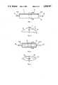
- FIG. 1is a longitudinal section of a degassing device
- FIG. 2is a cross-sectional view of the degassing device shown in FIG. 1;
- FIG. 3is a longitudinal section of another degassing device
- FIG. 4is a cross section of the degassing device shown in FIG. 3;
- FIG. 5shows a woven fabric in which warp and weft threads comprise capillaries
- FIG. 6is a cross section of a degassing device with an embedded woven fabric according to FIG. 5;
- FIG. 7is a diagram showing one application of the devices taught by the invention.
- FIG. 8is a longitudinal section of an embodiment of a degassing and filtering device according to the invention.
- FIG. 9is a longitudinal section of another embodiment of a degassing and filtering device according to the invention.
- the degassing capillarymay extend over the entire, or almost the entire, length of the casing, whereby in each case preferably at least one end of the capillary (capillaries) disposed in the axial direction of the casing is used as the outlet opening for the gas. Needless to say, either both ends of the degassing capillaries are outlet openings or the end not used as the outlet opening is closed against the passage of fluid.
- Suitable materials for the fluid-repellent, gas-permeable, microporous degassing capillariesare, for example, polypropylene, polyvinylidene fluoride or polytetrafluoroethylene.
- the manufacture of such degassing capillariescan be carried out, for example, in the manner described in West German Laid-open Patent Application No. 3,049,557 or West German Laid-open Patent Application No. 2,737,745.
- a particularly advantageous embodiment of the device according to the inventionresults if, during rotation about its longitudinal axis in any (swivelling) position, it performs a good degassing job.
- the device of the inventionby distributing a plurality of degassing capillaries along the circumference on the inner face of the casing jacket.
- the same functioncan alternatively, or additionally, be achieved if the degassing capillaries are disposed in such a way that they extend from one casing wall to the opposite casing wall, so that the degassing capillaries form with each other a net-like structure which, at least in part, is disposed perpendicularly to the direction of flow of the fluid to be degassed.
- the degassing capillariescan be interlaced with each other.
- a plurality of degassing capillaries parallel to each otheris used in the form of a small band.
- These capillariescan be disposed either in the direction of flow or perpendicular thereto.
- the small bandmay also have a tubular shape, which at one end, for example, is closed in the manner of a thimble.
- the shape of a small band or of a net-like structurecan be simply achieved by disposing the degassing capillaries as weft and/or warp threads of a woven fabric. If only the weft, or only the warp, threads are degassing capillaries, yarns or threads which need only be compatible with the fluid to be degassed are used for the other type of thread (warp or weft threads). As a rule, threads of synthetic polymers are used for this purpose.
- a wettable, gas-impermeable, microporous filtermay additionally be contained in the device of the invention.
- a filtersubdivides the casing into a first compartment with the inlet opening and a second compartment with the outlet opening, the degassing capillary or capillaries in the space between filter and casing wall being disposed at least above the filter. (Whenever reference is made herein that the degassing capillary is disposed above the filter, this means that the degassing capillary is placed above the filter in the casing when in the operating position.)
- Filters which are suitable for the filtration of the fluid and which may also be membranescan inherently have, or can have by means of a special treatment, the property of being wettable (for example, lyophilic or hydrophilic) by the fluid to be filtered.
- the fluid-repellente.g., lyophobic or hydrophobic
- gas-permeable materialfor the degassing capillary.
- Suitable materials of the filter membraneinclude, for example, polyamide-6,6, polyamide-6, cellulose, cellulose acetate and polyvinyl acetate (PVA).
- Suitable materials for the fluid-repellent gas-permeable microporous parts of the device according to the inventioninclude, for example, polypropylene, polyvinylidene fluoride or polytetrafluoroethylene.
- the average pore size for the filteris directed towards the particular filtering effect desired and is, for example, 0.2 micron for sterile filtration or 1 micron for particle filtration.
- the maximum pore size of the wettable, gas-impermeable microporous filter (membrane)must be such that the associated bubble pressure (i.e., the pressure at which gas penetrates through the filter layer by displacing the fluid from the pores) is higher than the filtration pressure.
- the bubble pressure, and thereby the filtration pressure that can be appliedincreases as the size of the largest pore of the wettable microporous filter layer decreases.
- the pore size of the fluid-repellent, gas-permeable, microporous degassing capillarymust be chosen such that the filtration pressure is lower than the pressure needed for fluid intrusion.
- the pressure for fluid intrusionalso known as the fluid-penetration pressure, increases as the maximum pore size of the degassing capillary decreases and as the difference of the surface tensions of fluid and the fluid-repellent gas-permeable microporous material increases.
- a reduction in the difference of the surface tension of fluid and materialcan be compensated for by reducing the pore size of the material, or by choosing a material with a suitable pore size. Where appropriate, the surface available for degassing must be increased. Moreover, the fluid-repellent property of a material can also be deleteriously affected or entirely lost at high fluid temperatures. This means that, for the porous parts of the device according to the invention which cause the gases to be separated from the fluid, it is necessary to choose a material with which the escape of fluid is prevented under specified operating conditions. By a simple preliminary test, one can ascertain whether the fluid-repellent property present in a porous material under normal conditions is still present under operating conditions as well.
- the device embodying the inventionis also suitable if, for its intended use, there is an appreciable over-pressure relative to the ambient pressure in the fluid, as may be the case, for example, with infusion filters with an upstream pump.
- the outlet openings of the degassing capillariesmay also be combined into a single outlet opening, so that a reduced pressure can be applied to the inner cavity of the degassing capillaries to increase their effectiveness.
- the filterhas at least one filter capillary and the inner cavity of the filter capillaries, at least in part, forms the second compartment. Compared with flat filters, a particularly large effective filter surface is obtained by means of filter capillaries.
- the degassing of the fluidcan be carried out with great success if the degassing capillary (capillaries) is (are) wound several times loosely around the filter capillary (capillaries) along the length thereof.
- the filter capillariesare disposed in the form of a bundle, along whose circumference the degassing capillaries are disposed.
- the degassing capillaries and filter setupcan lie beside each other in any desired arrangement.
- every filter capillarycan be disposed next to a degassing capillary, and every degassing capillary next to a filter capillary.
- filter capillaries and degassing capillariesare to be disposed beside each other, it has proved best to combine the filter capillaries and the degassing capillaries as weft and/or warp threads into one woven fabric or several woven fabrics. If only the weft threads or only the warp threads are capillaries, the yarns or threads, which preferably consist of synthetic polymers, but which must be compatible with the fluids to be degassed, are used for the other (warp or weft) threads.
- a devicein which the filter capillaries and degassing capillaries are disposed in a tubular casing in the form of an extended U.
- all ends of the capillariesare embedded in a sealing compound at one end of the casing in such a way that there terminate in the central area of the embedment point only filter capillaries and in the outer area thereof only degassing capillaries.
- the end of the casing provided with the sealing compoundis shut off by a downstream cap containing the outlet opening for the degassed fluid in such a way that the ends of the filter capillaries terminate inside, and the ends of the degassing capillaries terminate outside, the downstream cap.
- the ends of the degassing capillaries in the area of the sealing compoundprefferably be disposed at least substantially axially parallel to the casing.
- the cavities of the degassing capillariesit has proved particularly advantageous for the cavities of the degassing capillaries to be in communication with a circumferential channel formed by the downstream cap of the sealing compound and the casing.
- this embodimentit is made certain that, even if relatively large parts of the groove are covered by adhesive plaster, degassing will occur.
- a ring between cap end and sealing compoundhas proved the most satisfactory expedient.
- This ringmay be tapered toward the sealing compound, so that it penetrates in part into the sealing compound when the downstream cap is put in place.
- the ringcan also be inserted prior to introduction of the sealing compound and embedded therein. It may be bonded to the casing and/or to the downstream cap, e.g., by cementing, so that the downstream cap is bonded to the casing, for example, via the ring.
- This ringdoes not absolutely have to be circular. Polygons or elliptical rings can also be used.
- Materials commonly used for the embedment of capillarieswhich may be thermoplastic or self-curing, can be used for the sealing compound.
- Casings with practically all possible cross sectionsespecially with an elliptical, triangular or circular cross section, may be used as tubular casings.
- the degassing capillary 1is disposed in the upper area of the casing 2.
- the casing 2has, in cross section, a triangular outline, one side 7 of the triangular outline being much longer than the two other sides 8, so that only the side 7 can be used for placement on the patient's arm.
- the side 7is curved slightly inward.
- the degassing capillary 1 in the embodiment shownextends with certainty into the upper area of the degassing device, so that the gas bubbles rising during the flow through the casing 2 come into contact with the degassing capillary 1 and are evacuated through the microporous layer into the inner cavity of the degassing capillary 1.
- the two ends of the degassing capillary 1are each embedded into the end walls 3 of the casing 2 in such a way that the inner cavity is in communication with the surrounding atmosphere.
- the inner cavity of the degassing capillary 1forms two outlet openings 4a and 4b for the gas.
- the casing 12 of the degassing device illustrated in FIGS. 3 and 4has an oval cross section.
- two degassing capillaries 11are provided in this device.
- the ends of both degassing capillariesare again embedded into the end faces, each degassing capillary having two outlet openings 14a, 14b for the gas.
- the casing 12has an inlet opening 15 for the fluid to be degassed and an outlet opening 16 for the degassed fluid.
- FIG. 5shows schematically a woven fabric in which both the weft threads 17 and the warp threads 18 comprise degassing capillaries.
- a woven fabriccan be embedded between two casing parts 19, so that a close-meshed net is formed by the degassing capillaries to trap gas bubbles with certainty.
- the degassing capillarieshave outlet openings 20 for the gas.
- FIG. 7shows one application of a device 26 according to the invention.
- an infusion fluid 22is passed through a hose 24 to a device 26 for separating gas bubbles and filtering this infusion fluid.
- This degassing and filtering deviceis pasted onto the forearm A of a patient by means of an adhesive plaster 28.
- the feed rate of the infusion fluidcan be controlled by the dosing aid 23.
- the infusion fluidpasses through another hose 29 and an infusion needle 27 into the bloodstream.
- a degassing and filtering devicesuitable for such an application is shown in Figure 8.
- a tubular casing 30 with an inlet connection 37 for the fluid to be degassedis closed via a ring 32 by a downstream cap 31 with an outlet connection 36.
- the casing 30there are cut at least two grooves 40, in pairs and in diametrically opposed positions, into which are embedded, with sealing compound, the degassing capillaries 33 disposed in the form of a U in the casing 30, the two ends of the U being inserted into two diametrically opposed grooves.
- the ring 32 inserted into the casingcloses off the grooves 40, so that the ends of the degassing capillaries 33 are tightly embedded in the area of the ring 32.
- the ring 32has grooves or bores 41 in the outer rim, into which the ends of the degassing capillary are extended further, or which serve as an extension of the inside cavities of the degassing capillaries 33.
- the downstream cap 31 connected to the casing in a manner not shown herein (e.g., by means of snap locks)is supported on the interior of the ring 32.
- the downstream cap 31may also be connected to the ring 32 and/or the ring 32 may be connected to the casing 30, e.g., by ultrasonic welding.
- the ring 32serves at the same time to receive the sealing compound 35, into which are embedded filter capillaries 34, which are also introduced in the form of a U into the casing 30.
- the filter capillaries 34are surrounded by the degassing capillaries 33, so that the gas bubbles filtered off by the filter capillaries 34 can escape through the degassing capillaries 33 in any tilted position of the axis. If the degassing capillaries 33 are uniformly distributed along the inner circumference of the casing 30, the latter may have a circular-cylindrical cross section, because now rotation about the axis of the casing 30 is no longer of importance for venting off the degassing capillaries.
- the ends 38 of the degassing capillaries 33terminate in a circumferential groove 39 formed by the ring 32 and the downstream cap 31.
- the degassing operationis basically ensured.
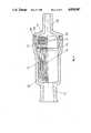
- FIG. 9shows another advantageous embodiment of a degassing and filtering device according to the invention.
- a filter-capillary bundle 44which is inserted in the form of a U into the casing 41, is wound helically within the casing 41 by a degassing capillary 45.
- the ends 46 of the filter capillaries 44, and along the outer circumferenceare embedded the ends 47 of the degassing capillaries 45, with the cavities of both capillary types remaining open to the outside.
- a downstream cap 42is formed in such a way that it subdivides the sealing compound into two areas.
- the central area, in which the ends 46 of the filter capillaries 44 terminate,runs into the outlet connection 49 of the downstream cap 42.
- the outer areacomprises a circumferential groove, which is formed by the downstream cap 42, the sealing compound 51 and the casing 41, and in which the ends 47 of the degassing capillaries 45 terminate in the circumferential groove.
- the downstream cap 42is connected by means of snap locks 43 to the casing 41, the snap locks 43 being formed as clips and latching into catches 52 of the casing 41.
- the casing 41has an inlet connection 48.
- the filter capillaries 34 or 44may be present in the form of several woven fabrics laminated one on top of the other, the filter capillaries 34 or 44 being present as warp threads in this woven fabric.
- the degassing capillaries 33additionally may also be disposed as warp threads in this woven fabric.
- the degassing capillariesmay also be woven only with each other as warp threads. In this case it is particularly recommended that a woven hose be used.
- the snap lock 43is formed not as a stud but as a circumferential ring, then this circumferential ring, the downstream cap 42, the sealing compound 51, and the casing 41 form a circulating annular duct in which a reduced pressure can be applied in the circumferential ring through an entry fitting not shown.
Landscapes
- Health & Medical Sciences (AREA)
- Chemical Kinetics & Catalysis (AREA)
- Chemical & Material Sciences (AREA)
- Life Sciences & Earth Sciences (AREA)
- General Health & Medical Sciences (AREA)
- Biomedical Technology (AREA)
- Heart & Thoracic Surgery (AREA)
- Hematology (AREA)
- Engineering & Computer Science (AREA)
- Animal Behavior & Ethology (AREA)
- Anesthesiology (AREA)
- Public Health (AREA)
- Veterinary Medicine (AREA)
- Vascular Medicine (AREA)
- Emergency Medicine (AREA)
- Separation Using Semi-Permeable Membranes (AREA)
- Degasification And Air Bubble Elimination (AREA)
- External Artificial Organs (AREA)
- Infusion, Injection, And Reservoir Apparatuses (AREA)
Abstract
Description
Claims (16)
Applications Claiming Priority (2)
| Application Number | Priority Date | Filing Date | Title |
|---|---|---|---|
| DE3624363ADE3624363C2 (en) | 1986-07-18 | 1986-07-18 | Device for separating gas bubbles from infusion liquids or liquids from the human body |
| DE3624363 | 1986-07-18 |
Publications (1)
| Publication Number | Publication Date |
|---|---|
| US4828587Atrue US4828587A (en) | 1989-05-09 |
Family
ID=6305497
Family Applications (1)
| Application Number | Title | Priority Date | Filing Date |
|---|---|---|---|
| US07/075,726Expired - LifetimeUS4828587A (en) | 1986-07-18 | 1987-07-20 | Device for separating gas bubbles from fluids |
Country Status (5)
| Country | Link |
|---|---|
| US (1) | US4828587A (en) |
| EP (1) | EP0254100B1 (en) |
| JP (1) | JPS6373971A (en) |
| DE (2) | DE3624363C2 (en) |
| ES (1) | ES2053473T3 (en) |
Cited By (33)
| Publication number | Priority date | Publication date | Assignee | Title |
|---|---|---|---|---|
| US4985055A (en)* | 1988-12-19 | 1991-01-15 | The Boc Group, Inc. | Liquid/gas separation device |
| US5032116A (en)* | 1991-01-09 | 1991-07-16 | Becton, Dickinson And Company | Flashback plug |
| US5190524A (en)* | 1990-02-10 | 1993-03-02 | Roland Wex | Device for bringing together several infusions and/or injections |
| US5221474A (en)* | 1990-12-28 | 1993-06-22 | Terumo Kabushiki Kaisha | Transfusion filtering device |
| US5279647A (en)* | 1990-12-04 | 1994-01-18 | Thermo Separation Products (California) Inc. | Methods and apparatus for degassing a liquid |
| USD351230S (en) | 1992-06-30 | 1994-10-04 | Baxter International Inc. | Filter for I.V. administration |
| US5439587A (en)* | 1993-07-27 | 1995-08-08 | Millipore Corporation | Self priming filter apparatus |
| US5500003A (en)* | 1993-11-09 | 1996-03-19 | Industrie Borla, S.P.A. | Transducer-protector device for biomedical haemodialysis lines |
| WO1997026030A1 (en)* | 1996-01-16 | 1997-07-24 | Medtronic, Inc. | Leak prevention in blood oxygenators |
| US5902490A (en)* | 1994-03-10 | 1999-05-11 | Hemasure, Inc. | Filtration method and device useable for removal of leukocytes and other blood components |
| US6010633A (en)* | 1997-03-06 | 2000-01-04 | Hemasure Inc. | Method of preventing air from becoming entrapped within a filtration device |
| US6251292B1 (en) | 1994-03-10 | 2001-06-26 | Hemasure, Inc. | Method of preventing air from becoming entrapped within a filtration device |
| US6342092B1 (en)* | 1999-10-07 | 2002-01-29 | General Dynamics Ots (Aerospace), Inc. | Apparatus to separate gas from a liquid flow |
| WO2002018037A3 (en)* | 2000-08-31 | 2002-06-06 | Millipore Corp | Gas vent filter construction incorporating a hollow fiber membrane assembly |
| US6537356B1 (en)* | 1999-08-06 | 2003-03-25 | Nathaniel M. Soriano | Gas and solid trap for an intravenous line |
| US6669762B2 (en)* | 2000-12-28 | 2003-12-30 | Nipro Corporation | Air trap for liquid circulation line |
| US20040000232A1 (en)* | 2001-11-13 | 2004-01-01 | Van Horne William J. | Device and method for exchanging oxygen and carbon dioxide between a gas and an aqueous liquid |
| US20040031744A1 (en)* | 1998-12-09 | 2004-02-19 | Jms Co., Ltd. | Infusion filter |
| EP1473073A1 (en)* | 2003-05-02 | 2004-11-03 | Norit Proces Technologie Holding B.V. | Membrane filter with deaeration and method for the manufacture thereof |
| US20040226542A1 (en)* | 2003-02-21 | 2004-11-18 | Ekstam Charles Bradley | Fuel/air separation system |
| US20070240569A1 (en)* | 2005-05-09 | 2007-10-18 | Nitto Denko Corporation | Degasifier |
| US20090045140A1 (en)* | 2005-04-25 | 2009-02-19 | Joseph Zahka | Method and apparatus for treating fluids to reduce microbubbles |
| US20100009243A1 (en)* | 2007-01-16 | 2010-01-14 | Primus Power Corporation | Electrochemical energy cell system |
| US20110049026A1 (en)* | 2009-08-26 | 2011-03-03 | Kolon Industries, Inc. | Hollow fiber membrane module for water purifier |
| US20130069087A1 (en)* | 2011-09-16 | 2013-03-21 | Ricoh Company, Ltd. | Multi-layer wiring substrate, active matrix substrate, image display apparatus using the same, and multi-layer wiring substrate manufacturing method |
| US20140137739A1 (en)* | 2012-11-20 | 2014-05-22 | Nitto Denko Corporation | Ventilation member |
| CN104144719A (en)* | 2011-12-20 | 2014-11-12 | 科克理工学院 | Bubble trap with variable volume |
| CN106139909A (en)* | 2016-08-24 | 2016-11-23 | 杭州汉膜新材料科技有限公司 | A kind of water purifier membrane module and method for packing thereof |
| US11020541B2 (en) | 2016-07-25 | 2021-06-01 | Icu Medical, Inc. | Systems, methods, and components for trapping air bubbles in medical fluid transfer modules and systems |
| CN113795320A (en)* | 2019-05-09 | 2021-12-14 | 德国诺玛公司 | Device for degassing liquids in liquid lines |
| USD948044S1 (en) | 2015-12-04 | 2022-04-05 | Icu Medical, Inc. | Fluid transfer device |
| EP4470586A1 (en)* | 2023-06-02 | 2024-12-04 | Illinois Tool Works Inc. | Intravenous filter air vent media protection and enhancement |
| US12194286B2 (en) | 2018-10-19 | 2025-01-14 | Yong Hyun Kim | Filter-integrated medicine transfer device and medicinal liquid injection apparatus including the same |
Families Citing this family (17)
| Publication number | Priority date | Publication date | Assignee | Title |
|---|---|---|---|---|
| JPH0252005A (en)* | 1988-08-12 | 1990-02-21 | Japan Gore Tex Inc | Deaeration mechanism |
| WO1990011812A1 (en)* | 1989-04-07 | 1990-10-18 | Baxter International Inc. | Gas separating and venting filter and method of making same |
| DE4020840C2 (en)* | 1990-06-29 | 1994-06-09 | Fresenius Ag | Device for degassing a liquid |
| DE4035487A1 (en)* | 1990-11-08 | 1992-05-14 | Wolf Gmbh Richard | Medical body orifice rinsing device - uses pressurised propulsion gas passing through wall of chamber communicating with rinsed body aperture |
| DE4211907A1 (en)* | 1991-04-19 | 1992-11-05 | Rene Baltus | Liquid contained gas or solid content measuring device - contains degassing or solid removal cell in form of tube or flat membrane supplied with absorbent or reagent by pump |
| DE4122551A1 (en)* | 1991-07-08 | 1993-01-14 | Bayerische Motoren Werke Ag | Compact membrane air bleeding assembly for vehicle radiator system - which seals air-filled gap at radiator head to prevent escape of water droplets and vapour |
| US5922201A (en)* | 1992-02-12 | 1999-07-13 | Mitsubishi Rayon Co., Ltd. | Hollow fiber membrane module |
| DE69316325T2 (en)* | 1992-02-12 | 1998-05-28 | Mitsubishi Rayon Co | HOLLOW FIBER MEMBRANE MODULE |
| DE19545404A1 (en)* | 1995-12-06 | 1997-06-12 | Kevin Business Corp | Excretion of air from blood containing air |
| DE19650407A1 (en)* | 1996-12-05 | 1998-06-10 | Kevin Business Corp | Blood-gas separation method and device |
| DE19650406A1 (en) | 1996-12-05 | 1998-06-18 | Kevin Business Corp | Blood suction device |
| WO1998028064A1 (en) | 1996-12-21 | 1998-07-02 | Akzo Nobel Nv | Membrane module with hollow fibre membranes arranged in layers |
| DE19701994A1 (en)* | 1997-01-22 | 1998-07-23 | Mann & Hummel Filter | filter |
| DE19719555A1 (en) | 1997-05-09 | 1998-11-12 | Kevin Business Corp | Method and device for separating gas from gaseous blood |
| NL1006137C2 (en)* | 1997-05-27 | 1998-12-01 | Prime Water Systems N V | Ultrafiltration device. |
| EP2696963B1 (en) | 2011-04-13 | 2021-03-24 | 3M Innovative Properties Company | Macroporous filtration membrane |
| CN106139331A (en)* | 2016-07-28 | 2016-11-23 | 湖北康友医用器材有限公司 | In a kind of infusion unit titrimeter use from gas deflation assembly |
Citations (18)
| Publication number | Priority date | Publication date | Assignee | Title |
|---|---|---|---|---|
| DE1959679A1 (en)* | 1968-12-26 | 1970-07-09 | Baxter Laboratories Inc | Filter insert, especially for removing gas from a flow |
| US3523408A (en)* | 1968-04-02 | 1970-08-11 | Pall Corp | Gas separator |
| DE2317750A1 (en)* | 1972-05-01 | 1973-11-15 | Pall Corp | DEVICE FOR SEPARATING GASES AND LIQUIDS AND FILTERING LIQUIDS AND GASES |
| US3778971A (en)* | 1970-09-29 | 1973-12-18 | Rhone Poulenc Sa | Device for purging gas from a liquid |
| US3854907A (en)* | 1973-12-10 | 1974-12-17 | Millipore Corp | Vented filter holder |
| DE2604003A1 (en)* | 1976-02-03 | 1977-08-11 | Messerschmitt Boelkow Blohm | DEVICE FOR SEPARATING GASES FROM LIQUIDS |
| DE2737745A1 (en)* | 1976-08-30 | 1978-03-09 | Akzo Gmbh | MICROPOROUS POLYMER STRUCTURES AND THE PROCESS FOR THEIR PRODUCTION |
| DE2851838A1 (en)* | 1977-11-30 | 1979-05-31 | Baxter Travenol Lab | GAS SEPARATION AND VENTILATION FILTER UNIT AND METHOD FOR ATTACHING A FILTER ELEMENT |
| DE3011681A1 (en)* | 1979-03-26 | 1980-10-02 | Jelco Lab | VENTILATED FILTERING DEVICE FOR FILTERING PARENTERAL OR OTHER LIQUIDS |
| DE3039557A1 (en)* | 1979-11-09 | 1981-05-21 | Umberto Firenze Fortini | ELASTIC HINGE JOINT FOR THE BRACKETS OF AN EYE FRAME |
| US4278084A (en)* | 1979-10-19 | 1981-07-14 | Baxter Travenol Laboratories, Inc. | Non air-blocking filter |
| US4336036A (en)* | 1981-01-08 | 1982-06-22 | Amf Incorporated | Filter and method of making same |
| DE3143456A1 (en)* | 1981-11-03 | 1983-05-19 | B. Braun Melsungen Ag, 3508 Melsungen | Infusion device |
| DE3304951A1 (en)* | 1983-02-12 | 1984-08-16 | Akzo Gmbh, 5600 Wuppertal | DEVICE FOR FILTERING A LIQUID |
| WO1985000987A1 (en)* | 1983-08-29 | 1985-03-14 | Millipore Corporation | I.v. filter apparatus |
| WO1985000986A1 (en)* | 1983-08-30 | 1985-03-14 | Baxter Travenol Laboratories, Inc. | In-line filter |
| US4615694A (en)* | 1985-02-15 | 1986-10-07 | Burron Medical Inc. | Vented cone filter |
| US4636307A (en)* | 1983-09-16 | 1987-01-13 | Mitsubishi Rayon Co., Ltd. | Hollow-fiber filtering module and water purification device utilizing it |
Family Cites Families (3)
| Publication number | Priority date | Publication date | Assignee | Title |
|---|---|---|---|---|
| US3631654A (en)* | 1968-10-03 | 1972-01-04 | Pall Corp | Gas purge device |
| US4326957A (en)* | 1978-07-21 | 1982-04-27 | Pall Corporation | Vented filter spigot for intravenous liquid administration apparatus |
| DE3049557A1 (en)* | 1980-12-31 | 1982-07-29 | Akzo Gmbh, 5600 Wuppertal | POROESE TUBES |
- 1986
- 1986-07-18DEDE3624363Apatent/DE3624363C2/ennot_activeExpired - Lifetime
- 1987
- 1987-07-03ESES87109568Tpatent/ES2053473T3/ennot_activeExpired - Lifetime
- 1987-07-03EPEP87109568Apatent/EP0254100B1/ennot_activeExpired - Lifetime
- 1987-07-03DEDE3750058Tpatent/DE3750058D1/ennot_activeExpired - Fee Related
- 1987-07-17JPJP62177379Apatent/JPS6373971A/enactivePending
- 1987-07-20USUS07/075,726patent/US4828587A/ennot_activeExpired - Lifetime
Patent Citations (24)
| Publication number | Priority date | Publication date | Assignee | Title |
|---|---|---|---|---|
| US3523408A (en)* | 1968-04-02 | 1970-08-11 | Pall Corp | Gas separator |
| GB1221625A (en)* | 1968-12-26 | 1971-02-03 | Baxter Laboratories Inc | Gas purging fluid filter |
| DE1959679A1 (en)* | 1968-12-26 | 1970-07-09 | Baxter Laboratories Inc | Filter insert, especially for removing gas from a flow |
| US3778971A (en)* | 1970-09-29 | 1973-12-18 | Rhone Poulenc Sa | Device for purging gas from a liquid |
| CH565578A5 (en)* | 1972-05-01 | 1975-08-29 | Pall Corp | |
| DE2317750A1 (en)* | 1972-05-01 | 1973-11-15 | Pall Corp | DEVICE FOR SEPARATING GASES AND LIQUIDS AND FILTERING LIQUIDS AND GASES |
| DE2458405A1 (en)* | 1973-12-10 | 1975-06-12 | Millipore Corp | FILTER HOLDER |
| US3854907A (en)* | 1973-12-10 | 1974-12-17 | Millipore Corp | Vented filter holder |
| DE2604003A1 (en)* | 1976-02-03 | 1977-08-11 | Messerschmitt Boelkow Blohm | DEVICE FOR SEPARATING GASES FROM LIQUIDS |
| DE2737745A1 (en)* | 1976-08-30 | 1978-03-09 | Akzo Gmbh | MICROPOROUS POLYMER STRUCTURES AND THE PROCESS FOR THEIR PRODUCTION |
| DE2851838A1 (en)* | 1977-11-30 | 1979-05-31 | Baxter Travenol Lab | GAS SEPARATION AND VENTILATION FILTER UNIT AND METHOD FOR ATTACHING A FILTER ELEMENT |
| US4276170A (en)* | 1978-08-16 | 1981-06-30 | Critikon, Inc. | Vented flexible filtration device for use in administering parenteral liquids |
| DE3011681A1 (en)* | 1979-03-26 | 1980-10-02 | Jelco Lab | VENTILATED FILTERING DEVICE FOR FILTERING PARENTERAL OR OTHER LIQUIDS |
| US4278084A (en)* | 1979-10-19 | 1981-07-14 | Baxter Travenol Laboratories, Inc. | Non air-blocking filter |
| DE3039557A1 (en)* | 1979-11-09 | 1981-05-21 | Umberto Firenze Fortini | ELASTIC HINGE JOINT FOR THE BRACKETS OF AN EYE FRAME |
| US4336036A (en)* | 1981-01-08 | 1982-06-22 | Amf Incorporated | Filter and method of making same |
| DE3143456A1 (en)* | 1981-11-03 | 1983-05-19 | B. Braun Melsungen Ag, 3508 Melsungen | Infusion device |
| DE3304951A1 (en)* | 1983-02-12 | 1984-08-16 | Akzo Gmbh, 5600 Wuppertal | DEVICE FOR FILTERING A LIQUID |
| US4531954A (en)* | 1983-02-12 | 1985-07-30 | Akzo Nv | Arrangement for filtering a liquid |
| WO1985000987A1 (en)* | 1983-08-29 | 1985-03-14 | Millipore Corporation | I.v. filter apparatus |
| WO1985000986A1 (en)* | 1983-08-30 | 1985-03-14 | Baxter Travenol Laboratories, Inc. | In-line filter |
| US4568366A (en)* | 1983-08-30 | 1986-02-04 | Baxter Laboratories, Inc. | In-line filter |
| US4636307A (en)* | 1983-09-16 | 1987-01-13 | Mitsubishi Rayon Co., Ltd. | Hollow-fiber filtering module and water purification device utilizing it |
| US4615694A (en)* | 1985-02-15 | 1986-10-07 | Burron Medical Inc. | Vented cone filter |
Cited By (54)
| Publication number | Priority date | Publication date | Assignee | Title |
|---|---|---|---|---|
| US4985055A (en)* | 1988-12-19 | 1991-01-15 | The Boc Group, Inc. | Liquid/gas separation device |
| US5190524A (en)* | 1990-02-10 | 1993-03-02 | Roland Wex | Device for bringing together several infusions and/or injections |
| US5279647A (en)* | 1990-12-04 | 1994-01-18 | Thermo Separation Products (California) Inc. | Methods and apparatus for degassing a liquid |
| US5221474A (en)* | 1990-12-28 | 1993-06-22 | Terumo Kabushiki Kaisha | Transfusion filtering device |
| US5032116A (en)* | 1991-01-09 | 1991-07-16 | Becton, Dickinson And Company | Flashback plug |
| USD351230S (en) | 1992-06-30 | 1994-10-04 | Baxter International Inc. | Filter for I.V. administration |
| US5439587A (en)* | 1993-07-27 | 1995-08-08 | Millipore Corporation | Self priming filter apparatus |
| US5500003A (en)* | 1993-11-09 | 1996-03-19 | Industrie Borla, S.P.A. | Transducer-protector device for biomedical haemodialysis lines |
| US6015500A (en)* | 1994-03-10 | 2000-01-18 | Hemasure Inc. | Filtration device useable for removal of leukocytes and other blood components |
| US6251292B1 (en) | 1994-03-10 | 2001-06-26 | Hemasure, Inc. | Method of preventing air from becoming entrapped within a filtration device |
| US5902490A (en)* | 1994-03-10 | 1999-05-11 | Hemasure, Inc. | Filtration method and device useable for removal of leukocytes and other blood components |
| AU711194B2 (en)* | 1996-01-16 | 1999-10-07 | Medtronic, Inc. | Leak prevention in blood oxygenators |
| WO1997026030A1 (en)* | 1996-01-16 | 1997-07-24 | Medtronic, Inc. | Leak prevention in blood oxygenators |
| US6010633A (en)* | 1997-03-06 | 2000-01-04 | Hemasure Inc. | Method of preventing air from becoming entrapped within a filtration device |
| US20040031744A1 (en)* | 1998-12-09 | 2004-02-19 | Jms Co., Ltd. | Infusion filter |
| US6537356B1 (en)* | 1999-08-06 | 2003-03-25 | Nathaniel M. Soriano | Gas and solid trap for an intravenous line |
| US6342092B1 (en)* | 1999-10-07 | 2002-01-29 | General Dynamics Ots (Aerospace), Inc. | Apparatus to separate gas from a liquid flow |
| US6432178B2 (en) | 1999-10-07 | 2002-08-13 | General Dynamics Ots (Aerospace), Inc. | Apparatus to separate gas from a liquid flow |
| WO2002018037A3 (en)* | 2000-08-31 | 2002-06-06 | Millipore Corp | Gas vent filter construction incorporating a hollow fiber membrane assembly |
| US6669762B2 (en)* | 2000-12-28 | 2003-12-30 | Nipro Corporation | Air trap for liquid circulation line |
| US20040000232A1 (en)* | 2001-11-13 | 2004-01-01 | Van Horne William J. | Device and method for exchanging oxygen and carbon dioxide between a gas and an aqueous liquid |
| US20050199222A1 (en)* | 2003-02-21 | 2005-09-15 | Charles Bradley Ekstam | Fuel/air separation system |
| US20040226542A1 (en)* | 2003-02-21 | 2004-11-18 | Ekstam Charles Bradley | Fuel/air separation system |
| US6892710B2 (en) | 2003-02-21 | 2005-05-17 | Charles Bradley Ekstam | Fuel/air separation system |
| US7025048B2 (en) | 2003-02-21 | 2006-04-11 | Charles Bradley Ekstam | Fuel/air separation system |
| CN1572360B (en)* | 2003-05-02 | 2010-05-12 | 诺里特加工技术控股有限公司 | Membrane filter with deaeration and method for the manufacture thereof |
| US20050000883A1 (en)* | 2003-05-02 | 2005-01-06 | Kouters Lucas Johannes Cornelis | Membrane filter with deaeration and method for the manufacture thereof |
| EP1473073A1 (en)* | 2003-05-02 | 2004-11-03 | Norit Proces Technologie Holding B.V. | Membrane filter with deaeration and method for the manufacture thereof |
| US7465393B2 (en) | 2003-05-02 | 2008-12-16 | Norit Proces Technologie Holding B.V. | Membrane filter with deaeration and method for the manufacture thereof |
| NL1023332C2 (en)* | 2003-05-02 | 2004-11-03 | Norit Proces Technologie Holdi | Membrane filter with venting and method for its manufacture. |
| US9333443B2 (en) | 2005-04-25 | 2016-05-10 | Entegris, Inc. | Method and apparatus for treating fluids to reduce microbubbles |
| US20090045140A1 (en)* | 2005-04-25 | 2009-02-19 | Joseph Zahka | Method and apparatus for treating fluids to reduce microbubbles |
| US8777189B2 (en)* | 2005-04-25 | 2014-07-15 | Entegris, Inc. | Method and apparatus for treating fluids to reduce microbubbles |
| US7686867B2 (en)* | 2005-05-09 | 2010-03-30 | Nitto Denko Corporation | Degasifier |
| US20070240569A1 (en)* | 2005-05-09 | 2007-10-18 | Nitto Denko Corporation | Degasifier |
| US20110070468A9 (en)* | 2007-01-16 | 2011-03-24 | Primus Power Corporation | Electrochemical energy cell system |
| US20100009243A1 (en)* | 2007-01-16 | 2010-01-14 | Primus Power Corporation | Electrochemical energy cell system |
| US20110049026A1 (en)* | 2009-08-26 | 2011-03-03 | Kolon Industries, Inc. | Hollow fiber membrane module for water purifier |
| US20130069087A1 (en)* | 2011-09-16 | 2013-03-21 | Ricoh Company, Ltd. | Multi-layer wiring substrate, active matrix substrate, image display apparatus using the same, and multi-layer wiring substrate manufacturing method |
| US8723193B2 (en)* | 2011-09-16 | 2014-05-13 | Ricoh Company, Ltd. | Multi-layer wiring substrate, active matrix substrate, image display apparatus using the same, and multi-layer wiring substrate manufacturing method |
| CN104144719B (en)* | 2011-12-20 | 2017-06-23 | 科克理工学院 | Bubble entrapment device with variable volume |
| CN104144719A (en)* | 2011-12-20 | 2014-11-12 | 科克理工学院 | Bubble trap with variable volume |
| US20140137739A1 (en)* | 2012-11-20 | 2014-05-22 | Nitto Denko Corporation | Ventilation member |
| US9528622B2 (en)* | 2012-11-20 | 2016-12-27 | Nitto Denko Corporation | Ventilation member |
| USD948044S1 (en) | 2015-12-04 | 2022-04-05 | Icu Medical, Inc. | Fluid transfer device |
| USD1018849S1 (en) | 2015-12-04 | 2024-03-19 | Icu Medical, Inc. | Fluid transfer device |
| US11020541B2 (en) | 2016-07-25 | 2021-06-01 | Icu Medical, Inc. | Systems, methods, and components for trapping air bubbles in medical fluid transfer modules and systems |
| US11583637B2 (en) | 2016-07-25 | 2023-02-21 | Icu Medical, Inc. | Systems, methods, and components for trapping air bubbles in medical fluid transfer modules and systems |
| US11951293B2 (en) | 2016-07-25 | 2024-04-09 | Icu Medical, Inc. | Systems, methods, and components for trapping air bubbles in medical fluid transfer modules and systems |
| US12280249B2 (en) | 2016-07-25 | 2025-04-22 | Icu Medical, Inc. | Systems, methods, and components for trapping air bubbles in medical fluid transfer modules and systems |
| CN106139909A (en)* | 2016-08-24 | 2016-11-23 | 杭州汉膜新材料科技有限公司 | A kind of water purifier membrane module and method for packing thereof |
| US12194286B2 (en) | 2018-10-19 | 2025-01-14 | Yong Hyun Kim | Filter-integrated medicine transfer device and medicinal liquid injection apparatus including the same |
| CN113795320A (en)* | 2019-05-09 | 2021-12-14 | 德国诺玛公司 | Device for degassing liquids in liquid lines |
| EP4470586A1 (en)* | 2023-06-02 | 2024-12-04 | Illinois Tool Works Inc. | Intravenous filter air vent media protection and enhancement |
Also Published As
| Publication number | Publication date |
|---|---|
| DE3624363C2 (en) | 1995-06-08 |
| ES2053473T3 (en) | 1994-08-01 |
| EP0254100A2 (en) | 1988-01-27 |
| DE3624363A1 (en) | 1988-01-28 |
| EP0254100B1 (en) | 1994-06-15 |
| JPS6373971A (en) | 1988-04-04 |
| EP0254100A3 (en) | 1988-12-07 |
| DE3750058D1 (en) | 1994-07-21 |
Similar Documents
| Publication | Publication Date | Title |
|---|---|---|
| US4828587A (en) | Device for separating gas bubbles from fluids | |
| US4531954A (en) | Arrangement for filtering a liquid | |
| US5779674A (en) | Fluid gas removal drip chamber | |
| EP0153928B1 (en) | In-line filter | |
| US4615694A (en) | Vented cone filter | |
| US4276170A (en) | Vented flexible filtration device for use in administering parenteral liquids | |
| US4157965A (en) | Blood treating device | |
| CA2698408C (en) | Safety vent structure for extracorporeal circuit | |
| US4344777A (en) | Directed flow bubble trap for arterial blood | |
| KR930012046B1 (en) | Selective Permeable Hollow Fiber Ends and Fluid Separators Comprising the Same | |
| WO2006044255A2 (en) | A membrane contactor and method of making the same | |
| JP2002529323A (en) | Two-part vessel pressure compensator | |
| JPH0542220A (en) | Transfusion filter | |
| WO2003047718B1 (en) | Filter media surface modification for enhanced sealing and apparatus utilizing the same | |
| CA1188180A (en) | Venting assembly for a sealed body fluid drainage device | |
| US10654006B1 (en) | Devices and methods for infusing gas into a liquid | |
| WO1990011812A1 (en) | Gas separating and venting filter and method of making same | |
| EP0247213A1 (en) | Filter for eliminating air | |
| US4253967A (en) | Blood treating method | |
| JP2003111837A (en) | Hollow fiber membrane type artificial lung | |
| EP0222032A1 (en) | Blood oxygenator | |
| JPH1147564A (en) | Gas dissolution and dissolved gas removal module | |
| JP7003685B2 (en) | Filtration module | |
| JP2549382Y2 (en) | Hollow fiber membrane module | |
| US4231880A (en) | Assembly for the closure of the end of a flattened tube |
Legal Events
| Date | Code | Title | Description |
|---|---|---|---|
| AS | Assignment | Owner name:AKZO NV, VELPERWEG 76, 6824 BM ARNHEM, THE NETHERL Free format text:ASSIGNMENT OF ASSIGNORS INTEREST.;ASSIGNORS:BAURMEISTER, ULRICH;PELGER, MICHAEL;REEL/FRAME:004808/0124 Effective date:19870727 Owner name:AKZO NV, VELPERWEG 76, 6824 BM ARNHEM, THE NETHERL Free format text:ASSIGNMENT OF ASSIGNORS INTEREST;ASSIGNORS:BAURMEISTER, ULRICH;PELGER, MICHAEL;REEL/FRAME:004808/0124 Effective date:19870727 | |
| STCF | Information on status: patent grant | Free format text:PATENTED CASE | |
| FEPP | Fee payment procedure | Free format text:PAYOR NUMBER ASSIGNED (ORIGINAL EVENT CODE: ASPN); ENTITY STATUS OF PATENT OWNER: LARGE ENTITY | |
| FPAY | Fee payment | Year of fee payment:4 | |
| FEPP | Fee payment procedure | Free format text:PAYER NUMBER DE-ASSIGNED (ORIGINAL EVENT CODE: RMPN); ENTITY STATUS OF PATENT OWNER: LARGE ENTITY Free format text:PAYOR NUMBER ASSIGNED (ORIGINAL EVENT CODE: ASPN); ENTITY STATUS OF PATENT OWNER: LARGE ENTITY | |
| FPAY | Fee payment | Year of fee payment:8 | |
| FEPP | Fee payment procedure | Free format text:PAYER NUMBER DE-ASSIGNED (ORIGINAL EVENT CODE: RMPN); ENTITY STATUS OF PATENT OWNER: LARGE ENTITY Free format text:PAYOR NUMBER ASSIGNED (ORIGINAL EVENT CODE: ASPN); ENTITY STATUS OF PATENT OWNER: LARGE ENTITY | |
| FPAY | Fee payment | Year of fee payment:12 | |
| AS | Assignment | Owner name:MEMBRANA GMBH, GERMANY Free format text:ASSIGNMENT OF ASSIGNORS INTEREST;ASSIGNOR:AKZO NOBEL N.V.;REEL/FRAME:012841/0636 Effective date:20010420 Owner name:AKZO NOBEL N.V., NETHERLANDS Free format text:CHANGE OF NAME WITH TRANSLATION;ASSIGNOR:AKZO N.V.;REEL/FRAME:012841/0809 Effective date:19940225 |