US4828509A - Sealed housing system for modular type connectors - Google Patents
Sealed housing system for modular type connectorsDownload PDFInfo
- Publication number
- US4828509A US4828509AUS07/114,279US11427987AUS4828509AUS 4828509 AUS4828509 AUS 4828509AUS 11427987 AUS11427987 AUS 11427987AUS 4828509 AUS4828509 AUS 4828509A
- Authority
- US
- United States
- Prior art keywords
- connector
- component
- components
- female
- mating
- Prior art date
- Legal status (The legal status is an assumption and is not a legal conclusion. Google has not performed a legal analysis and makes no representation as to the accuracy of the status listed.)
- Expired - Fee Related
Links
- 230000013011matingEffects0.000claimsabstractdescription21
- 230000000717retained effectEffects0.000claimsabstractdescription3
- 230000007613environmental effectEffects0.000claimsdescription2
- 230000003247decreasing effectEffects0.000claims2
- 238000007789sealingMethods0.000abstractdescription6
- 239000012530fluidSubstances0.000abstractdescription2
- 239000007788liquidSubstances0.000description3
- 230000004075alterationEffects0.000description1
- 230000000295complement effectEffects0.000description1
- 230000008878couplingEffects0.000description1
- 238000010168coupling processMethods0.000description1
- 238000005859coupling reactionMethods0.000description1
- 238000003780insertionMethods0.000description1
- 230000037431insertionEffects0.000description1
- 238000006467substitution reactionMethods0.000description1
- 230000000153supplemental effectEffects0.000description1
Images

Classifications
- H—ELECTRICITY
- H01—ELECTRIC ELEMENTS
- H01R—ELECTRICALLY-CONDUCTIVE CONNECTIONS; STRUCTURAL ASSOCIATIONS OF A PLURALITY OF MUTUALLY-INSULATED ELECTRICAL CONNECTING ELEMENTS; COUPLING DEVICES; CURRENT COLLECTORS
- H01R13/00—Details of coupling devices of the kinds covered by groups H01R12/70 or H01R24/00 - H01R33/00
- H01R13/46—Bases; Cases
- H01R13/52—Dustproof, splashproof, drip-proof, waterproof, or flameproof cases
- H01R13/5219—Sealing means between coupling parts, e.g. interfacial seal
- B—PERFORMING OPERATIONS; TRANSPORTING
- B29—WORKING OF PLASTICS; WORKING OF SUBSTANCES IN A PLASTIC STATE IN GENERAL
- B29C—SHAPING OR JOINING OF PLASTICS; SHAPING OF MATERIAL IN A PLASTIC STATE, NOT OTHERWISE PROVIDED FOR; AFTER-TREATMENT OF THE SHAPED PRODUCTS, e.g. REPAIRING
- B29C66/00—General aspects of processes or apparatus for joining preformed parts
- B29C66/01—General aspects dealing with the joint area or with the area to be joined
- B29C66/05—Particular design of joint configurations
- B29C66/10—Particular design of joint configurations particular design of the joint cross-sections
- B29C66/12—Joint cross-sections combining only two joint-segments; Tongue and groove joints; Tenon and mortise joints; Stepped joint cross-sections
- B29C66/124—Tongue and groove joints
- B29C66/1244—Tongue and groove joints characterised by the male part, i.e. the part comprising the tongue
- B29C66/12445—Tongue and groove joints characterised by the male part, i.e. the part comprising the tongue having the tongue on the side
- B—PERFORMING OPERATIONS; TRANSPORTING
- B29—WORKING OF PLASTICS; WORKING OF SUBSTANCES IN A PLASTIC STATE IN GENERAL
- B29C—SHAPING OR JOINING OF PLASTICS; SHAPING OF MATERIAL IN A PLASTIC STATE, NOT OTHERWISE PROVIDED FOR; AFTER-TREATMENT OF THE SHAPED PRODUCTS, e.g. REPAIRING
- B29C66/00—General aspects of processes or apparatus for joining preformed parts
- B29C66/01—General aspects dealing with the joint area or with the area to be joined
- B29C66/05—Particular design of joint configurations
- B29C66/10—Particular design of joint configurations particular design of the joint cross-sections
- B29C66/12—Joint cross-sections combining only two joint-segments; Tongue and groove joints; Tenon and mortise joints; Stepped joint cross-sections
- B29C66/124—Tongue and groove joints
- B29C66/1246—Tongue and groove joints characterised by the female part, i.e. the part comprising the groove
- B29C66/12461—Tongue and groove joints characterised by the female part, i.e. the part comprising the groove being rounded, i.e. U-shaped or C-shaped
- B—PERFORMING OPERATIONS; TRANSPORTING
- B29—WORKING OF PLASTICS; WORKING OF SUBSTANCES IN A PLASTIC STATE IN GENERAL
- B29C—SHAPING OR JOINING OF PLASTICS; SHAPING OF MATERIAL IN A PLASTIC STATE, NOT OTHERWISE PROVIDED FOR; AFTER-TREATMENT OF THE SHAPED PRODUCTS, e.g. REPAIRING
- B29C66/00—General aspects of processes or apparatus for joining preformed parts
- B29C66/01—General aspects dealing with the joint area or with the area to be joined
- B29C66/05—Particular design of joint configurations
- B29C66/10—Particular design of joint configurations particular design of the joint cross-sections
- B29C66/12—Joint cross-sections combining only two joint-segments; Tongue and groove joints; Tenon and mortise joints; Stepped joint cross-sections
- B29C66/124—Tongue and groove joints
- B29C66/1246—Tongue and groove joints characterised by the female part, i.e. the part comprising the groove
- B29C66/12463—Tongue and groove joints characterised by the female part, i.e. the part comprising the groove being tapered
- B—PERFORMING OPERATIONS; TRANSPORTING
- B29—WORKING OF PLASTICS; WORKING OF SUBSTANCES IN A PLASTIC STATE IN GENERAL
- B29C—SHAPING OR JOINING OF PLASTICS; SHAPING OF MATERIAL IN A PLASTIC STATE, NOT OTHERWISE PROVIDED FOR; AFTER-TREATMENT OF THE SHAPED PRODUCTS, e.g. REPAIRING
- B29C66/00—General aspects of processes or apparatus for joining preformed parts
- B29C66/01—General aspects dealing with the joint area or with the area to be joined
- B29C66/05—Particular design of joint configurations
- B29C66/10—Particular design of joint configurations particular design of the joint cross-sections
- B29C66/12—Joint cross-sections combining only two joint-segments; Tongue and groove joints; Tenon and mortise joints; Stepped joint cross-sections
- B29C66/124—Tongue and groove joints
- B29C66/1246—Tongue and groove joints characterised by the female part, i.e. the part comprising the groove
- B29C66/12469—Tongue and groove joints characterised by the female part, i.e. the part comprising the groove being asymmetric
- B—PERFORMING OPERATIONS; TRANSPORTING
- B29—WORKING OF PLASTICS; WORKING OF SUBSTANCES IN A PLASTIC STATE IN GENERAL
- B29C—SHAPING OR JOINING OF PLASTICS; SHAPING OF MATERIAL IN A PLASTIC STATE, NOT OTHERWISE PROVIDED FOR; AFTER-TREATMENT OF THE SHAPED PRODUCTS, e.g. REPAIRING
- B29C66/00—General aspects of processes or apparatus for joining preformed parts
- B29C66/01—General aspects dealing with the joint area or with the area to be joined
- B29C66/05—Particular design of joint configurations
- B29C66/10—Particular design of joint configurations particular design of the joint cross-sections
- B29C66/12—Joint cross-sections combining only two joint-segments; Tongue and groove joints; Tenon and mortise joints; Stepped joint cross-sections
- B29C66/128—Stepped joint cross-sections
- B—PERFORMING OPERATIONS; TRANSPORTING
- B29—WORKING OF PLASTICS; WORKING OF SUBSTANCES IN A PLASTIC STATE IN GENERAL
- B29C—SHAPING OR JOINING OF PLASTICS; SHAPING OF MATERIAL IN A PLASTIC STATE, NOT OTHERWISE PROVIDED FOR; AFTER-TREATMENT OF THE SHAPED PRODUCTS, e.g. REPAIRING
- B29C66/00—General aspects of processes or apparatus for joining preformed parts
- B29C66/50—General aspects of joining tubular articles; General aspects of joining long products, i.e. bars or profiled elements; General aspects of joining single elements to tubular articles, hollow articles or bars; General aspects of joining several hollow-preforms to form hollow or tubular articles
- B29C66/51—Joining tubular articles, profiled elements or bars; Joining single elements to tubular articles, hollow articles or bars; Joining several hollow-preforms to form hollow or tubular articles
- B29C66/52—Joining tubular articles, bars or profiled elements
- B29C66/522—Joining tubular articles
- B29C66/5221—Joining tubular articles for forming coaxial connections, i.e. the tubular articles to be joined forming a zero angle relative to each other
- B—PERFORMING OPERATIONS; TRANSPORTING
- B29—WORKING OF PLASTICS; WORKING OF SUBSTANCES IN A PLASTIC STATE IN GENERAL
- B29L—INDEXING SCHEME ASSOCIATED WITH SUBCLASS B29C, RELATING TO PARTICULAR ARTICLES
- B29L2031/00—Other particular articles
- B29L2031/34—Electrical apparatus, e.g. sparking plugs or parts thereof
- B29L2031/36—Plugs, connectors, or parts thereof
Definitions
- the present inventionrelates to connectors and, in particular, connectors providing a communication of electrical signals and gas pressure between the two sections thereof.
- connectors providing communication of changes in pressurerequire a sealed housing which provides the necessary pressure coupling.
- one or more O-rings of the same diameterare employed.
- identical O-rings disposed on the same surfacei.e., of the same radius
- the unitary connector according to the present inventionprovides both an electrical connection and communication of a pressure gradient in a single connector.
- the mating portions of the electrical connectorare retained within a sealed environment within male and femal connector components which allows the pressure gradient to be communicated between the two connector components of the same apertures through which the electrical connector mates.
- such pressure changesare communicated from the connector to the equipment by the interstitial space surrounding the electrical connector portions within the connector and to the equipment within the outer covering of the connecting wire. Redundant sealing is provided between the two mating connector components provided by molded O-ring-type seals disposed on the mating surfaces of the connector having different dimension, to provide a seal that is resistant to damage.
- the unitary connector according to the present inventionalso includes a molded-in umbrella-type shield to deflect liquids around the confronting portion of the connector components when fully seated.
- the present inventionprovides a reliable, inexpensive unitary modular connector resistant to wear and environmental damage.
- FIG. 1is a cross section of one embodiment of the two components of the present invention in a mated position
- FIG. 2is an exploded view of the connector elements according to one embodiment of the present invention.
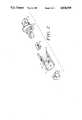
- FIG. 3is an isometric view of the male component of one embodiment of the connector showing the stepped sealing rings.
- the connector 20 shown in FIG. 1includes a male component 22 and a female component 24 having recesses 26 and 28, respectively, formed therein to receive the mating electrical connectors 40 and 44, discussed below and shown in FIG. 2.
- the aperture 26is extended to the distal end of the connector 30 to receive a cable (not shown) therein and formed to provide a pressure-tight seal to the external surface of the cable.
- the recess 28is connected to an enlarged opening 32 which receives the mating connector of FIG. 2 therein and permits equipment or cable connection to the connector component 24.
- a difference in pressureis communicated between the two sections 22 and 24 via pressure relief openings 34 and 36, molded in the respective connector portions. Therefore, the pressure present in one connector component is equalized to the pressure in the mating connecting component.
- FIG. 2An exploded view of the connector 20 is shown in FIG. 2 wherein the male component 22 of the connector 20 is shown in partial cut-away wherein one portion 40 of the electrical connector is received in the complementary opening 42 of the connector component 22.
- the electrical connector portion 40, as well as the mating electrical connector portion 44,typically comprise part numbers 940-SP-3046 and 6446-R/CL/CS, manufactured by Stewart Stamping Company, Yonkers, N.Y.
- the electrical connector portion 44is received in the female component 24 of the connector according to the present invention through the opening 32 and an aperture 46 through an internal wall 48 of the connector portion 24.
- the internal wall 48has the aperture 34 integrally molded therein to allow the pressure on either side of the wall 48 to equalize.
- the receiving end of the connector 24communicates with the opening 42 and opening 36 of the male connector component 22, which communicates with the cable opening (30 of FIG. 1) so that the pressure at the opening 32 becomes equal to the pressure at the rear opening 30 of the male connector component 22.
- Alternate embodiments of the present inventionprovide for fluid communication through the apertures which receive the electrical connector portions 40 and 44 and, in the further alternative, through the electrical connector portions 40 and 44.
- An additional feature of the connector 20 of the present inventionis the multiple seals 50 and 52 on the mating surface of the male component 22 of the connector 20 which engages the opening of the female component 24 to provide a reliable, gas-tight seal.
- the seals 50 and 52resemble O-ring elements and are disposed on stepped mating surfaces 54 and 56 of the connector component 22.
- the seals 50 and 52are molded as part of the connector element 22. The seals 50 and 52 mate with different surfaces in the female component providing redundant sealing surfaces should one of the sealing surfaces be damaged.
- the connector 20further provides an integral umbrella-like cover 56 as part of the male component 22, to surround a lip 58 of the female component 24 extending toward the mating component 22 having a cavity 62 formed therein.
- the outer edge of the confronting surfaces of the mating components 22 and 24are non-orthogonal to the outer surfaces of the connector 20, preferably being disposed at 45°.
Landscapes
- Connector Housings Or Holding Contact Members (AREA)
Abstract
Description
The present invention relates to connectors and, in particular, connectors providing a communication of electrical signals and gas pressure between the two sections thereof.
Frequently medical equipment requires interconnection of detachable elements having both electrical and pressure connections. Merely joining two different electrical and pressure connectors in a side-by-side arrangement makes the connector sensitive to insertion alignment and lateral spacing of the connectors, resulting in an expensive and complex connector.
Moreover, connectors providing communication of changes in pressure require a sealed housing which provides the necessary pressure coupling. Typically, in sealing two coaxially mating elements, one or more O-rings of the same diameter are employed. However, identical O-rings disposed on the same surface (i.e., of the same radius) may not provide a reliable gas-tight seal, as the singular mating surface is easily damaged, thus compromising the seal. Therefore, a connector thusly constructed is more likely to fail in usage.
Furthermore, modular connectors in medical usage are likely to be exposed to liquids. Normal connectors providing external mechanical attachments have exposed or unprotected confronting surfaces which do not provide the necessary environment resistance for the mating portions of the connectors. Supplemental shields applied around the connector are awkward to use and, as a result, frequently not used.
The unitary connector according to the present invention provides both an electrical connection and communication of a pressure gradient in a single connector. The mating portions of the electrical connector are retained within a sealed environment within male and femal connector components which allows the pressure gradient to be communicated between the two connector components of the same apertures through which the electrical connector mates. In one embodiment, such pressure changes are communicated from the connector to the equipment by the interstitial space surrounding the electrical connector portions within the connector and to the equipment within the outer covering of the connecting wire. Redundant sealing is provided between the two mating connector components provided by molded O-ring-type seals disposed on the mating surfaces of the connector having different dimension, to provide a seal that is resistant to damage.
The unitary connector according to the present invention also includes a molded-in umbrella-type shield to deflect liquids around the confronting portion of the connector components when fully seated. Thus, the present invention provides a reliable, inexpensive unitary modular connector resistant to wear and environmental damage.
These and further features of the present invention will be better understood by reading the following detailed description, taken together with the drawing wherein,
FIG. 1 is a cross section of one embodiment of the two components of the present invention in a mated position;
FIG. 2 is an exploded view of the connector elements according to one embodiment of the present invention; and
FIG. 3 is an isometric view of the male component of one embodiment of the connector showing the stepped sealing rings.
Theconnector 20 shown in FIG. 1 includes amale component 22 and afemale component 24 havingrecesses aperture 26 is extended to the distal end of the connector 30 to receive a cable (not shown) therein and formed to provide a pressure-tight seal to the external surface of the cable. Similarly, therecess 28 is connected to an enlargedopening 32 which receives the mating connector of FIG. 2 therein and permits equipment or cable connection to theconnector component 24. A difference in pressure is communicated between the twosections pressure relief openings
An exploded view of theconnector 20 is shown in FIG. 2 wherein themale component 22 of theconnector 20 is shown in partial cut-away wherein one portion 40 of the electrical connector is received in thecomplementary opening 42 of theconnector component 22. The electrical connector portion 40, as well as the mating electrical connector portion 44, typically comprise part numbers 940-SP-3046 and 6446-R/CL/CS, manufactured by Stewart Stamping Company, Yonkers, N.Y.
The electrical connector portion 44 is received in thefemale component 24 of the connector according to the present invention through theopening 32 and an aperture 46 through an internal wall 48 of theconnector portion 24. The internal wall 48 has theaperture 34 integrally molded therein to allow the pressure on either side of the wall 48 to equalize. The receiving end of theconnector 24 communicates with theopening 42 and opening 36 of themale connector component 22, which communicates with the cable opening (30 of FIG. 1) so that the pressure at theopening 32 becomes equal to the pressure at the rear opening 30 of themale connector component 22. Alternate embodiments of the present invention provide for fluid communication through the apertures which receive the electrical connector portions 40 and 44 and, in the further alternative, through the electrical connector portions 40 and 44.
An additional feature of theconnector 20 of the present invention is themultiple seals male component 22 of theconnector 20 which engages the opening of thefemale component 24 to provide a reliable, gas-tight seal. Theseals stepped mating surfaces connector component 22. Theseals connector element 22. Theseals
Theconnector 20 according to the present invention further provides an integral umbrella-like cover 56 as part of themale component 22, to surround alip 58 of thefemale component 24 extending toward themating component 22 having acavity 62 formed therein. The outer edge of the confronting surfaces of themating components connector 20, preferably being disposed at 45°. When themating components space 60 between thecomponents
The present invention is not limited to the embodiments and connector types shown. Any substitutions or alterations made by one of ordinary skill in the art are considered to be in the scope of the present application, which is not to be limited except by the claims which follow:
Claims (4)
1. A modular connector comprising:
a first connector component having an aperture including a first portion of an electrical connector retained therein; and
a second connector component having an aperture and receiving a second electrical connector portion therein, wherein
said second connector component is received by said first connection component and forms a pressure seal with said first connector component,
said first and second electrical portions are engaged when the first and second connectors are seated, and wherein
said apertures of said first and second connector components are disposed to communicate a pressure therebetween.
2. The modular connector of claim 1 further including double seal means for providing a gas-tight pressure seal between said first and second connector components.
3. A modular connector comprising:
a female component including an aperture comprising a plurality of longitudinal portions having successively decreasing relative dimension; and
a male component received by said female component, including a portion received by said female component and comprising a plurality of longitudinal portions having successively increasing relative dimension, each longitudinal portion including a surrounding outwardly protruding seal for providing a pressure seal with said aperture in said female component when inserted therein;
wherein said female and male components have apertures which communicate a pressure therebetween.
4. A modular connector comprising:
a female component including an aperture comprising a plurality of longitudinal portions having successively decreasing relative dimension; and
a male component received by said female component, including a portion received by said female component and comprising a plurality of longitudinal portions having successively increasing relative dimension, each longitudinal portion including a surrounding outwardly protruding seal for providing a pressure seal with said aperture in said female component when inserted therein;
wherein one of said components further includes a portion forming a cavity at the mating surface opening toward the mating component, and wherein the other said component includes a protrusion extending toward the mating said component to be received within said cavity for providing an environmental resistant connection when the respective components are fully mated, wherein the outward confronting surfaces of the mating components are non-perpendicular to the outer surface of the component.
Priority Applications (1)
| Application Number | Priority Date | Filing Date | Title |
|---|---|---|---|
| US07/114,279US4828509A (en) | 1987-10-27 | 1987-10-27 | Sealed housing system for modular type connectors |
Applications Claiming Priority (1)
| Application Number | Priority Date | Filing Date | Title |
|---|---|---|---|
| US07/114,279US4828509A (en) | 1987-10-27 | 1987-10-27 | Sealed housing system for modular type connectors |
Publications (1)
| Publication Number | Publication Date |
|---|---|
| US4828509Atrue US4828509A (en) | 1989-05-09 |
Family
ID=22354310
Family Applications (1)
| Application Number | Title | Priority Date | Filing Date |
|---|---|---|---|
| US07/114,279Expired - Fee RelatedUS4828509A (en) | 1987-10-27 | 1987-10-27 | Sealed housing system for modular type connectors |
Country Status (1)
| Country | Link |
|---|---|
| US (1) | US4828509A (en) |
Cited By (9)
| Publication number | Priority date | Publication date | Assignee | Title |
|---|---|---|---|---|
| US5033297A (en)* | 1989-12-04 | 1991-07-23 | Instrumentation Northwest, Inc. | Submersible sensor |
| EP0630073A3 (en)* | 1993-06-14 | 1995-08-23 | Sumitomo Wiring Systems | Rubber plug for waterproof connector. |
| US6290551B1 (en)* | 2000-02-29 | 2001-09-18 | Fci Usa, Inc. | Electrical connector having ultrasonically welded housing pieces |
| US6343953B2 (en)* | 2000-03-21 | 2002-02-05 | Yazaki Coproation | Structure for assembling a housing and a connector |
| US6375487B1 (en)* | 2000-04-27 | 2002-04-23 | Ge Medical Systems Information Technologies, Inc. | Removable connector cable having bend and strain relief with integral seal |
| US20060093281A1 (en)* | 2004-10-28 | 2006-05-04 | Kesler James R | Fiber optic connector |
| WO2008031526A1 (en)* | 2006-09-13 | 2008-03-20 | Wabco Gmbh | Electric plug connector having a guiding |
| US20130336710A1 (en)* | 2012-06-14 | 2013-12-19 | Tien-Ming Chou | Plastic Unit |
| CN110997289A (en)* | 2017-08-08 | 2020-04-10 | 罗伯特·博世有限公司 | Connecting assembly and method for welding together a first plastic part and a second plastic part |
Citations (7)
| Publication number | Priority date | Publication date | Assignee | Title |
|---|---|---|---|---|
| US3601761A (en)* | 1969-08-28 | 1971-08-24 | Arthur M Harris | Waterproof locking-type electric plug and receptacle coupling |
| US3953099A (en)* | 1973-12-10 | 1976-04-27 | Bunker Ramo Corporation | One-piece environmental removable contact connector |
| US3998515A (en)* | 1975-09-25 | 1976-12-21 | International Telephone And Telegraph Corporation | Hermetic electrical penetrator |
| US4498719A (en)* | 1977-12-27 | 1985-02-12 | Allied Corporation | Environmental connector assembly |
| US4693540A (en)* | 1983-03-31 | 1987-09-15 | Bicc Public Limited Company | Pressure regulating devices |
| US4709123A (en)* | 1984-09-13 | 1987-11-24 | Honda Giken Kogyo Kabushiki Kaisha | Electric component for motor vehicles |
| US4711509A (en)* | 1985-12-05 | 1987-12-08 | General Motors Corporation | Electrical connector |
- 1987
- 1987-10-27USUS07/114,279patent/US4828509A/ennot_activeExpired - Fee Related
Patent Citations (7)
| Publication number | Priority date | Publication date | Assignee | Title |
|---|---|---|---|---|
| US3601761A (en)* | 1969-08-28 | 1971-08-24 | Arthur M Harris | Waterproof locking-type electric plug and receptacle coupling |
| US3953099A (en)* | 1973-12-10 | 1976-04-27 | Bunker Ramo Corporation | One-piece environmental removable contact connector |
| US3998515A (en)* | 1975-09-25 | 1976-12-21 | International Telephone And Telegraph Corporation | Hermetic electrical penetrator |
| US4498719A (en)* | 1977-12-27 | 1985-02-12 | Allied Corporation | Environmental connector assembly |
| US4693540A (en)* | 1983-03-31 | 1987-09-15 | Bicc Public Limited Company | Pressure regulating devices |
| US4709123A (en)* | 1984-09-13 | 1987-11-24 | Honda Giken Kogyo Kabushiki Kaisha | Electric component for motor vehicles |
| US4711509A (en)* | 1985-12-05 | 1987-12-08 | General Motors Corporation | Electrical connector |
Cited By (15)
| Publication number | Priority date | Publication date | Assignee | Title |
|---|---|---|---|---|
| US5033297A (en)* | 1989-12-04 | 1991-07-23 | Instrumentation Northwest, Inc. | Submersible sensor |
| EP0630073A3 (en)* | 1993-06-14 | 1995-08-23 | Sumitomo Wiring Systems | Rubber plug for waterproof connector. |
| US6033261A (en)* | 1993-06-14 | 2000-03-07 | Sumitomo Wiring Systems, Ltd. | Rubber plug for waterproof connector |
| US6039603A (en)* | 1993-06-14 | 2000-03-21 | Sumitomo Wiring Systems, Ltd. | Rubber plug for waterproof connector |
| US6290551B1 (en)* | 2000-02-29 | 2001-09-18 | Fci Usa, Inc. | Electrical connector having ultrasonically welded housing pieces |
| US6343953B2 (en)* | 2000-03-21 | 2002-02-05 | Yazaki Coproation | Structure for assembling a housing and a connector |
| US6375487B1 (en)* | 2000-04-27 | 2002-04-23 | Ge Medical Systems Information Technologies, Inc. | Removable connector cable having bend and strain relief with integral seal |
| US20060093281A1 (en)* | 2004-10-28 | 2006-05-04 | Kesler James R | Fiber optic connector |
| US7128475B2 (en) | 2004-10-28 | 2006-10-31 | Schweitzer Engineering Laboratories, Inc. | Fiber optic connector |
| WO2008031526A1 (en)* | 2006-09-13 | 2008-03-20 | Wabco Gmbh | Electric plug connector having a guiding |
| US20100015841A1 (en)* | 2006-09-13 | 2010-01-21 | Thomas Bolik | Electric plug connector having a guiding |
| US8075333B2 (en) | 2006-09-13 | 2011-12-13 | Wabco Gmbh | Electric plug connector with guide |
| CN101512844B (en)* | 2006-09-13 | 2014-08-20 | 威伯科有限公司 | Electric plug connector having a guiding |
| US20130336710A1 (en)* | 2012-06-14 | 2013-12-19 | Tien-Ming Chou | Plastic Unit |
| CN110997289A (en)* | 2017-08-08 | 2020-04-10 | 罗伯特·博世有限公司 | Connecting assembly and method for welding together a first plastic part and a second plastic part |
Similar Documents
| Publication | Publication Date | Title |
|---|---|---|
| EP0251655B2 (en) | Underwater electrical connector | |
| US5197898A (en) | Multi-contact electrical connector with one-piece seal | |
| US7338214B1 (en) | Method and apparatus for sealing fiber optic connectors for industrial applications | |
| US3719918A (en) | Electrical connector | |
| US6332787B1 (en) | Wet-mateable electro-optical connector | |
| US2881406A (en) | Moisture seal for connectors | |
| CN101378162B (en) | Connector, jack socket component, electronic equipment and plug component | |
| RU2653188C1 (en) | Connector assembly | |
| US11493697B2 (en) | Optical fiber adapter | |
| US4455056A (en) | Multi-pin high voltage connector | |
| US4828509A (en) | Sealed housing system for modular type connectors | |
| US6254428B1 (en) | Waterproof structure for connector | |
| US6196873B1 (en) | Waterproof connector | |
| EP0477278B1 (en) | Pressure compensating connector assembly | |
| US6036543A (en) | Connector assembly | |
| US20030032321A1 (en) | Sealed connector | |
| CN114079180B (en) | Connector | |
| CN112970152B (en) | Waterproof electric connector | |
| US20070049111A1 (en) | Electrical plug-and-socket connector | |
| US6309252B1 (en) | Waterproof connector | |
| EP0493375B1 (en) | Electrical connector | |
| CN1147710A (en) | Seal carrying contact for connector assembly | |
| CN115483572A (en) | Connectors and wires with connectors | |
| US6132256A (en) | Design of a lambda module with mating plug | |
| EP0440743B1 (en) | Pressure compensating connector assembly |
Legal Events
| Date | Code | Title | Description |
|---|---|---|---|
| AS | Assignment | Owner name:HEWLETT-PACKARD COMPANY, PALO ALTO, CA. A CA. CORP Free format text:ASSIGNMENT OF ASSIGNORS INTEREST.;ASSIGNOR:VOGEL, GREGORY G.;REEL/FRAME:004804/0946 Effective date:19871026 Owner name:HEWLETT-PACKARD COMPANY,CALIFORNIA Free format text:ASSIGNMENT OF ASSIGNORS INTEREST;ASSIGNOR:VOGEL, GREGORY G.;REEL/FRAME:004804/0946 Effective date:19871026 | |
| FEPP | Fee payment procedure | Free format text:PAYOR NUMBER ASSIGNED (ORIGINAL EVENT CODE: ASPN); ENTITY STATUS OF PATENT OWNER: LARGE ENTITY | |
| FPAY | Fee payment | Year of fee payment:4 | |
| FPAY | Fee payment | Year of fee payment:8 | |
| REMI | Maintenance fee reminder mailed | ||
| LAPS | Lapse for failure to pay maintenance fees | ||
| FP | Lapsed due to failure to pay maintenance fee | Effective date:20010509 | |
| STCH | Information on status: patent discontinuation | Free format text:PATENT EXPIRED DUE TO NONPAYMENT OF MAINTENANCE FEES UNDER 37 CFR 1.362 |