US4828060A - Auxiliary drive circuit for an electric assist steering system - Google Patents
Auxiliary drive circuit for an electric assist steering systemDownload PDFInfo
- Publication number
- US4828060A US4828060AUS07/160,825US16082588AUS4828060AUS 4828060 AUS4828060 AUS 4828060AUS 16082588 AUS16082588 AUS 16082588AUS 4828060 AUS4828060 AUS 4828060A
- Authority
- US
- United States
- Prior art keywords
- drive circuit
- main drive
- assist motor
- sensing
- auxiliary
- Prior art date
- Legal status (The legal status is an assumption and is not a legal conclusion. Google has not performed a legal analysis and makes no representation as to the accuracy of the status listed.)
- Expired - Fee Related
Links
Images

Classifications
- B—PERFORMING OPERATIONS; TRANSPORTING
- B62—LAND VEHICLES FOR TRAVELLING OTHERWISE THAN ON RAILS
- B62D—MOTOR VEHICLES; TRAILERS
- B62D5/00—Power-assisted or power-driven steering
- B62D5/04—Power-assisted or power-driven steering electrical, e.g. using an electric servo-motor connected to, or forming part of, the steering gear
- B62D5/0457—Power-assisted or power-driven steering electrical, e.g. using an electric servo-motor connected to, or forming part of, the steering gear characterised by control features of the drive means as such
- B62D5/0481—Power-assisted or power-driven steering electrical, e.g. using an electric servo-motor connected to, or forming part of, the steering gear characterised by control features of the drive means as such monitoring the steering system, e.g. failures
- B62D5/0484—Power-assisted or power-driven steering electrical, e.g. using an electric servo-motor connected to, or forming part of, the steering gear characterised by control features of the drive means as such monitoring the steering system, e.g. failures for reaction to failures, e.g. limp home
Definitions
- the present inventionrelates to an electric assist steering system and is particularly directed to a circuit for providing a continued source of electric power to operate an assist motor in the event of a main drive circuit failure.
- auxiliary or backup power sourcein a power assist steering system is known in the art.
- a primary power sourceis employed during normal operation of the steering system to drive a power assist motor.
- a backup power sourceis usually maintained in a standby mode and is enabled for operation in the event of a failure of the primary power source.
- power assistremains available by way of the backup power source. Once the primary power source is restored to working order, the backup power source is placed back into the standby mode.
- U.S. Pat. No. 3,280,557 to Sattavaradiscloses a hydraulic power assist steering system having a primary pump and an auxiliary pump. Pressurized fluid is used to drive a hydraulic motor which provides the power assist.
- the primary pumpis driven by the vehicle engine and is the main source of pressurized fluid for the power assist motor.
- the auxiliary pumpis driven by the vehicle engine or by a separate electric motor.
- the output pressure from the primary pumpis monitored by a pressure sensor. When the primary pump output pressure is less than a predetermined value, the auxiliary pump is actuated. In such an event, power assist remains available, the pressurized fluid to drive the hydraulic power assist motor being supplied by the auxiliary pump.
- European Patent Application No. 84112152.8, Publication No. 0137491discloses a microcomputer-based, fail-safe, steering control system.
- Power assistis provided by an electric assist motor which is electrically connectable between the positive terminal of the vehicle battery and ground potential through a switching transistor.
- a relay switchhas its electrical contacts connected in parallel across the transistor. The relay contacts are normally closed. During normal operation, the relay is energized so that the contacts are open. The transistor is switched between an OFF condition and an ON condition by the microcomputer to control the amount of current through the electric assist motor. Should the microcomputer become disconnected from the battery, the relay contacts close to provide a current path to electrical ground so as to permit continued operation of the electric assist motor.
- the present inventionis directed to an electric assist steering system having an auxiliary drive circuit for providing a continued source of electric power to operate an electric power assist motor in the event of a failure of a main drive circuit.
- the present inventionprovides a novel and cost-effective auxiliary or backup drive circuit.
- the auxiliary drive circuit of the present inventionincludes an actuatable switching device electrically connected in parallel to an actuatable switching device in the main drive circuit.
- the auxiliary drive circuitfurther includes means to sense operation of the main drive circuit when steering torque is applied. If the main drive circuit should fail, i.e., not provide electrical power to drive the assist motor of the steering system when steering torque is applied, the auxiliary drive circuit is automatically actuated to connect the assist motor to a source of electrical power so as to provide the vehicle operator with continued power assist.
- An auxiliary drive circuitin accordance with the present invention, is for use in an electric power assist steering system having an electric assist motor and a main drive circuit connectable to the electric assist motor through a mechanically actuatable reversing switch assembly.
- the main drive circuitenergizes the electric assist motor in response to an output signal from a steering torsion sensing device by controlling the amount of current through the electric assist motor from a source of electrical energy.
- a value of the output signal from the torsion sensing devicevaries as a function of applied steering torque.
- the auxiliary drive circuitcomprises means for, when actuated, providing an auxiliary connection between the source of electrical energy and the mechanically actuatable reversing switch assembly through the electric assist motor.
- the auxiliary drive circuitfurther includes fault detection means for sensing a failure in the main drive circuit.
- the fault detection meansincludes first means for sensing an electrical output signal from the torsion sensing device and for outputting one electrical signal when applied steering torque is equal to or less than a predetermined value and a second electrical signal when applied steering torque is greater than the predetermined value.
- the fault detection meansfurther includes second means for sensing application of electrical power by the main drive circuit to the electric assist motor when applied steering torque is greater than the predetermined amount and for outputting one electrical signal when the main drive circuit is applying electrical power to the electric assist motor and a second electrical signal when the main drive circuit is not applying electrical power to the electric assist motor.
- the auxiliary drive circuitfurther includes means for actuating the auxiliary connection means in response to (i) the first sensing means indicating applied steering torque above a predetermined amount and (ii) the second sensing means indicating the main drive circuit is not applying electrical power to the electric assist motor.
- a main drive circuitincludes a modulator circuit for generating a pulse-width modulated signal in response to the output signal from a torsion sensing device.
- the main drive circuitfurther includes an actuatable field-effect transistor ("FET") which is connected between a mechanically actuatable reversing switch assembly and one potential of the vehicle battery.
- FETfield-effect transistor
- the FETis switched between an OFF condition and an ON condition to control the current flow through an electric assist motor.
- the current flowis functionally related to the duty cycle of the pulse-width modulated signal.
- An auxiliary drive circuitincludes a silicon controlled rectifier ("SCR") which is connected in parallel with the FET in the main drive circuit.
- a fault detector circuit in the auxiliary drive circuitincludes two comparators. One comparator is responsive to the output signal from the torsion sensing device, and the other comparator is responsive to an output signal from the main drive circuit. The outputs of the comparators are ANDED to provide the output signal of the fault detector circuit.
- the fault detector circuitprovides an output signal indicative thereof.
- This output signal from the fault detector circuitis latched to trigger and maintain the SCR in an ON condition.
- the latched output signal of the fault detector circuitis reset by cycling the vehicle ignition switch.
- the auxiliary drive circuitis a modification of the auxiliary drive circuit in the first embodiment.
- the modified auxiliary drive circuitincludes an identical fault detector circuit as in the first embodiment, and also includes an actuatable FET connected in parallel to the actuatable FET in the main drive circuit.
- the modified auxiliary drive circuitfurther includes a second modulator circuit for generating a pulse-width modulated signal in response to the output signal from the torsion sensing device.
- the FET in the modified auxiliary drive circuitis switched between an OFF condition and an ON condition to control the current flow through the electric assist motor in response to applied steering torque.
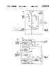
- FIG. 1is a schematic block diagram of a power assist steering system incorporating control circuitry made in accordance with the present invention
- FIG. 2is a schematic block diagram illustrating an embodiment of the control circuitry of FIG. 1;
- FIG. 3is a detailed schematic circuit diagram illustrating the fault detector circuit shown in FIG. 2;
- FIG. 4is a schematic block diagram illustrating another embodiment of the control circuitry of FIG. 1.
- a power assist steering system 10includes a steering wheel 12 operatively connected to a steering member 14 through a rack and pinion gear set 16 as is well known in the art.
- the steering member 14is in force transmitting engagement with steerable wheels 18, 20 of the vehicle.
- the steering wheel 12is connected to an input shaft 22 which is in turn connected to a pinion shaft 24 through a torsion bar 26.
- the input shaft 22 and the pinion shaft 24are relatively rotatable.
- the torsion bar 26resists such relative rotation.
- torqueis applied to the steering wheel 12.
- the amount of applied torque necessary to accomplish a steering maneuveris a function of the road surface friction and the speed of the vehicle.
- the input shaft 22rotates relative to the pinion shaft 24 by an amount which is a function of the applied steering torque and the resiliency characteristics of the torsion bar 26.
- a position sensor 28is provided for sensing the amount of relative rotation between the input shaft 22 and the pinion shaft 24. The position sensor 28 in combination with the torsion bar 26 provides a torque sensor 32.
- An electric assist motor 36circumscribes the steering member 14 and is drivably coupled thereto through a ball nut drive arrangement (not shown).
- a ball nut drive arrangement(not shown).
- One such ball nut drive arrangement that can be utilized with the present inventionis fully described in U.S. Pat. No. 4,515,054 to Drutchas, now reissued U.S. Pat. No. Re. 32,222, which is hereby fully incorporated herein by reference.
- a mechanical switch assembly 40is connected to the input shaft 22 and to the pinion shaft 24 across the torsion bar 26.
- the mechanical switch assembly 40includes four mechanically actuatable switches 42, 44, 46, and 48 connected in an "H" network.
- the switches 42, 44, 46 and 48are mechanically coupled across the torsion bar 26 in such a fashion that twisting of the torsion bar causes actuation of the switches in pairs.
- the four switchesare normally open when no torque is applied to the steering wheel 12.
- the switchesclose in pairs upon application of steering torque to the steering wheel 12. If steering torque is applied to the steering wheel 12 in one direction, switches 42, 48 close. If steering torque is applied to the steering wheel 12 in the other direction, switches 44, 46 close.
- the junction of switches 42, 44is connected to one terminal of the electric assist motor 36.
- the junction of switches 46, 48is connected to the other terminal of the electric assist motor 36.
- the junction of switches 44, 48is electrically connected to a main drive circuit 50 and to an auxiliary drive circuit 60.
- the junction of switches 42, 46is connectable to the positive potential of a source of electrical energy, such as, the vehicle battery.
- the main drive circuit 50includes a modulator circuit 70 having its input connected to the torque sensor 32.
- the output of the modulator circuit 70is is operatively connected to the control input of a field effect transistor ("FET") 72.
- FETfield effect transistor
- One terminal of the FET 72is connected to electrical ground and the other terminal is connected to the junction of switches 44, 48.
- the modulator circuit 70outputs a pulse-width modulated signal having a duty cycle that varies as a function of the output signal of the torque sensor 32.
- the current through the electric assist motor 36varies as a function of the ON time of the FET 72.
- the switches 42, 44, 46, 48control the direction of electric current through the motor 36 while the modulator circuit 70 controls the amount of current in response to the sensed applied steering torque.
- the auxiliary drive circuit 60includes a fault detector circuit 80 having one input operatively connected to the output of the torque sensor 32. Another input of the fault detector circuit 80 is operatively connected to the junction of switches 44, 48. The output of the fault detector circuit 80 is operatively connected to a latch 84.
- the fault detector circuit 80includes a first comparator 90 having its noninverting input connected to the junction of switches 44, 48 through a resistor/capacitor ("RC") network 92.
- a voltage dividing network 94is operatively connected across the vehicle battery and coupled to the inverting input of comparator 90 to provide a reference voltage.
- the RC network 92provides a DC voltage having a value that varies as a function of the duty cycle of the output of the main drive circuit 50.
- the value of the voltage reference input to comparator 90is equal to a value which is slightly less than the maximum steady-state value present across the capacitor in the RC network 92 when the main drive circuit is connected to the electric assist motor through the reversing switch assembly 40 and FET 72 is OFF.
- the voltage across the capacitor in network 92is ground.
- the output of comparator 90is then at a digital LOW.
- the RC network 92is connected to the battery potential B+through the motor coil of the electric assist motor 36 and the capacitor charges.
- the voltage across the capacitor in network 92is then equal to the battery voltage B+.
- the network 94provides a reference voltage to the inverting input having a value slightly less than the battery voltage B+. Therefore, as soon as a pair of switches close in assembly 40 and the capacitor in network 92 charges to B+, the output of 90 switches to a digital HIGH.
- comparator 90The voltage value at the noninverting input of comparator 90 decreases as the ON time of FET 72 increases.
- the output of comparator 90switches to a digital LOW.
- the fault detector circuit 80further includes a second comparator 100 having its noninverting input connected to the torque sensor 32 and its inverting input connected to a voltage dividing network 102.
- the voltage dividing network 102provides a voltage reference to comparator 100.
- the torque sensorin accordance with a preferred embodiment, outputs a minimum voltage value V1 when no torque is applied to the steering wheel 12. After an amount of torque greater than a predetermined amount is applied to the steering wheel 12 that insures that a pair of switches in assembly 40 are closed, the value of the torque signal increases regardless of the direction of the applied torque.
- the value of the reference voltage provided by network 102is equal to V1 plus a predetermined amount.
- the output of comparator 100When no torque is applied to the steering wheel 12, the output of comparator 100 is a digital LOW. When a sufficient amount of torque is applied to the steering wheel 12 so as to increase the torque signal output to a value greater than the predetermined reference value (V1+) at the inverting input of comparator 100, the output of comparator 100 switches to a digital HIGH. It will be appreciated that the reference voltage (V1+) at the inverting input of comparator 100 must be a value sufficient to insure the main drive circuit begins to modulate before the torque signal reaches a value equal to V1+. Under normal operating conditions, the output of comparator 90 must switch to a digital LOW before the output of comparator 100 switches to a digital HIGH. The main drive circuit should be drawing current through the electric assist motor by the time the output signal reaches a value equal to V1+.
- the output of comparator 90 and comparator 100are operatively connected to an AND gate 110.
- the output of the AND gate 110is operatively connected to the latch 84.
- the fault detector circuit 80outputs a digital HIGH from the AND gate 110 when (1) steering torque is applied to the vehicle steering wheel greater than a predetermined value, and (2) the FET 72 of the main drive circuit 50 is not modulating. Such an occurrence is considered a fault condition.
- a fault conditionwill occur if the modulator circuit 70 or the FET 72 is defective. Also, a fault condition will occur if an open circuit exists between the modulator circuit and the FET or if the FET becomes disconnected from either the reversing switch assembly or the ground potential of the vehicle battery.
- the latch 84When the output of AND gate 110 is in the digital HIGH state, the latch 84 is set and may be reset by cycling a vehicle ignition switch 120 operatively connected to the latch 84.
- the output of latch 84is connected to the control input of a silicon controlled rectifier ("SCR") 124.
- SCRsilicon controlled rectifier
- the SCR 124is operatively connected between the junction of switches 44, 48 and electrical ground. Once a fault is detected by the fault detector circuit 80, the latch 84 is set. The SCR 124 is thereby turned ON to provide maximum power assist to the steering system 10 upon closure of a pair of switches in the mechanical switch assembly 40.
- FIG. 4illustrates a second embodiment of the present invention.
- the auxiliary drive circuit 60'includes a fault detector circuit 80' identical to the fault detector circuit described above with regard to FIG. 2.
- a latch 84'is set.
- a modulator circuit 130is operatively connected to the output of the torque sensor 32 and outputs a pulse-width modulated signal to a first input of an AND gate 132.
- the duty cycle of the output signal of modulator circuit 130functionally related to applied steering torque.
- the output of the latch 84'is operatively connected to a second input of the AND gate 132.
- a digital HIGHis output to the AND gate 132.
- the output of AND gate 132is a pulse-width modulated signal having a duty cycle equal to the duty cycle of the output of the modulator circuit 130.
- the output of the AND gate 132is operatively connected to a drive circuit 134 which is, in turn, operatively connected to the control input of a FET 140.
- the FET 140has one terminal connected to electrical ground and the other terminal connected to the junction of switches 44, 48 of the mechanical switch assembly 40. Current flow through the electric assist motor 36 varies as a function of the ON time of the FET 140.
Landscapes
- Engineering & Computer Science (AREA)
- Chemical & Material Sciences (AREA)
- Combustion & Propulsion (AREA)
- Transportation (AREA)
- Mechanical Engineering (AREA)
- Power Steering Mechanism (AREA)
- Steering Control In Accordance With Driving Conditions (AREA)
Abstract
Description
Claims (14)
Priority Applications (1)
| Application Number | Priority Date | Filing Date | Title |
|---|---|---|---|
| US07/160,825US4828060A (en) | 1988-02-26 | 1988-02-26 | Auxiliary drive circuit for an electric assist steering system |
Applications Claiming Priority (1)
| Application Number | Priority Date | Filing Date | Title |
|---|---|---|---|
| US07/160,825US4828060A (en) | 1988-02-26 | 1988-02-26 | Auxiliary drive circuit for an electric assist steering system |
Publications (1)
| Publication Number | Publication Date |
|---|---|
| US4828060Atrue US4828060A (en) | 1989-05-09 |
Family
ID=22578615
Family Applications (1)
| Application Number | Title | Priority Date | Filing Date |
|---|---|---|---|
| US07/160,825Expired - Fee RelatedUS4828060A (en) | 1988-02-26 | 1988-02-26 | Auxiliary drive circuit for an electric assist steering system |
Country Status (1)
| Country | Link |
|---|---|
| US (1) | US4828060A (en) |
Cited By (10)
| Publication number | Priority date | Publication date | Assignee | Title |
|---|---|---|---|---|
| US4957182A (en)* | 1988-04-28 | 1990-09-18 | Mitsubishi Denki Kabushiki Kaisha | Electric power steering apparatus |
| EP0421766A1 (en)* | 1989-10-03 | 1991-04-10 | Mitsubishi Denki Kabushiki Kaisha | Motorized power steering apparatus |
| DE4029828A1 (en)* | 1989-09-20 | 1991-04-25 | Hitachi Ltd | DEVICE FOR DETECTING THE ROTATIONAL ANGLE OF A ROTATING SHAFT AND ROTATION CONTROL DEVICE USING THIS DEVICE |
| FR2699998A1 (en)* | 1992-12-30 | 1994-07-01 | Valeo Systemes Dessuyage | Measuring sensor, associated measuring device and application to a vehicle power steering device. |
| US5414627A (en)* | 1992-08-17 | 1995-05-09 | Mitsubishi Denki Kabushiki Kaisha | Electric power steering control device for automotive vehicle |
| US5747950A (en)* | 1992-12-11 | 1998-05-05 | Danfoss A/S | Steering system for vehicles or ships |
| US20070055908A1 (en)* | 2005-09-06 | 2007-03-08 | Honda Elesys Co., Ltd. | Redundant power supply circuit and motor driving circuit |
| KR100816413B1 (en)* | 2001-11-02 | 2008-03-25 | 주식회사 만도 | Complementary device in electronically controlled power steering system |
| DE102004044728B4 (en)* | 2003-09-16 | 2008-06-12 | Hitachi, Ltd. | Power steering system |
| US20110015828A1 (en)* | 2008-03-06 | 2011-01-20 | Jtekt Corporation | Electric power steering device |
Citations (16)
| Publication number | Priority date | Publication date | Assignee | Title |
|---|---|---|---|---|
| US2716706A (en)* | 1955-08-30 | Palmer | ||
| US2954671A (en)* | 1958-07-14 | 1960-10-04 | Le Tourneau Westinghouse Compa | Power steering means |
| US3041465A (en)* | 1960-05-31 | 1962-06-26 | Vivian E Ayre | Auxiliary power supply |
| US3280557A (en)* | 1965-03-11 | 1966-10-25 | Ford Motor Co | Safety control circuit for power steering unit |
| US3418487A (en)* | 1966-05-25 | 1968-12-24 | U C Lite Mfg Company | Emergency power supply system |
| US3434282A (en)* | 1967-03-14 | 1969-03-25 | Dura Corp | Safety backup system for power steering |
| US3463261A (en)* | 1968-03-28 | 1969-08-26 | Bendix Corp | Failsafe power steering system |
| US3795285A (en)* | 1972-04-03 | 1974-03-05 | Caterpillar Tractor Co | Steering system for articulated vehicles |
| US3913324A (en)* | 1974-05-01 | 1975-10-21 | Deere & Co | Flow-sensing switch for backup steering system |
| US3995711A (en)* | 1976-03-18 | 1976-12-07 | Deere & Company | Vehicle power steering electro-hydraulic safety backup system |
| US4238690A (en)* | 1978-10-23 | 1980-12-09 | Bell Telephone Laboratories, Incorporated | AC-DC switching regulator to supply uninterruptible power |
| US4342922A (en)* | 1981-02-05 | 1982-08-03 | General Electric Company | AC Fail-detect and battery switchover circuit for multi-bus power supply |
| US4345660A (en)* | 1979-12-26 | 1982-08-24 | Deere & Company | Vehicle emergency steering system |
| EP0137491A2 (en)* | 1983-10-13 | 1985-04-17 | Nissan Motor Co., Ltd. | Fail safe steering effort control system |
| US4598787A (en)* | 1984-11-30 | 1986-07-08 | Trw Inc. | Control apparatus for power assist steering system |
| US4751978A (en)* | 1987-03-16 | 1988-06-21 | Trw Inc. | Electric assist steering system with alternator power source |
- 1988
- 1988-02-26USUS07/160,825patent/US4828060A/ennot_activeExpired - Fee Related
Patent Citations (17)
| Publication number | Priority date | Publication date | Assignee | Title |
|---|---|---|---|---|
| US2716706A (en)* | 1955-08-30 | Palmer | ||
| US2954671A (en)* | 1958-07-14 | 1960-10-04 | Le Tourneau Westinghouse Compa | Power steering means |
| US3041465A (en)* | 1960-05-31 | 1962-06-26 | Vivian E Ayre | Auxiliary power supply |
| US3280557A (en)* | 1965-03-11 | 1966-10-25 | Ford Motor Co | Safety control circuit for power steering unit |
| US3418487A (en)* | 1966-05-25 | 1968-12-24 | U C Lite Mfg Company | Emergency power supply system |
| US3434282A (en)* | 1967-03-14 | 1969-03-25 | Dura Corp | Safety backup system for power steering |
| US3463261A (en)* | 1968-03-28 | 1969-08-26 | Bendix Corp | Failsafe power steering system |
| US3795285A (en)* | 1972-04-03 | 1974-03-05 | Caterpillar Tractor Co | Steering system for articulated vehicles |
| US3913324A (en)* | 1974-05-01 | 1975-10-21 | Deere & Co | Flow-sensing switch for backup steering system |
| US3995711A (en)* | 1976-03-18 | 1976-12-07 | Deere & Company | Vehicle power steering electro-hydraulic safety backup system |
| US4238690A (en)* | 1978-10-23 | 1980-12-09 | Bell Telephone Laboratories, Incorporated | AC-DC switching regulator to supply uninterruptible power |
| US4345660A (en)* | 1979-12-26 | 1982-08-24 | Deere & Company | Vehicle emergency steering system |
| US4342922A (en)* | 1981-02-05 | 1982-08-03 | General Electric Company | AC Fail-detect and battery switchover circuit for multi-bus power supply |
| EP0137491A2 (en)* | 1983-10-13 | 1985-04-17 | Nissan Motor Co., Ltd. | Fail safe steering effort control system |
| US4624335A (en)* | 1983-10-13 | 1986-11-25 | Nissan Motor Co., Ltd. | Fail safe steering effort control system |
| US4598787A (en)* | 1984-11-30 | 1986-07-08 | Trw Inc. | Control apparatus for power assist steering system |
| US4751978A (en)* | 1987-03-16 | 1988-06-21 | Trw Inc. | Electric assist steering system with alternator power source |
Cited By (15)
| Publication number | Priority date | Publication date | Assignee | Title |
|---|---|---|---|---|
| US4957182A (en)* | 1988-04-28 | 1990-09-18 | Mitsubishi Denki Kabushiki Kaisha | Electric power steering apparatus |
| DE4029828A1 (en)* | 1989-09-20 | 1991-04-25 | Hitachi Ltd | DEVICE FOR DETECTING THE ROTATIONAL ANGLE OF A ROTATING SHAFT AND ROTATION CONTROL DEVICE USING THIS DEVICE |
| US5239490A (en)* | 1989-09-20 | 1993-08-24 | Hitachi, Ltd. | Device for detecting rotation of rotary shaft and rotation controlling apparatus using the same |
| DE4029828C2 (en)* | 1989-09-20 | 1994-04-07 | Hitachi Ltd | Device for detecting the angle of rotation of a rotating shaft and torque detection device and power steering device equipped therewith |
| EP0421766A1 (en)* | 1989-10-03 | 1991-04-10 | Mitsubishi Denki Kabushiki Kaisha | Motorized power steering apparatus |
| US5039926A (en)* | 1989-10-03 | 1991-08-13 | Mitsubishi Denki K.K. | Motorized power steering apparatus |
| US5414627A (en)* | 1992-08-17 | 1995-05-09 | Mitsubishi Denki Kabushiki Kaisha | Electric power steering control device for automotive vehicle |
| US5747950A (en)* | 1992-12-11 | 1998-05-05 | Danfoss A/S | Steering system for vehicles or ships |
| EP0605326A1 (en)* | 1992-12-30 | 1994-07-06 | Valeo Systemes D'essuyage | Measurement sensor and its application to power steering |
| FR2699998A1 (en)* | 1992-12-30 | 1994-07-01 | Valeo Systemes Dessuyage | Measuring sensor, associated measuring device and application to a vehicle power steering device. |
| KR100816413B1 (en)* | 2001-11-02 | 2008-03-25 | 주식회사 만도 | Complementary device in electronically controlled power steering system |
| DE102004044728B4 (en)* | 2003-09-16 | 2008-06-12 | Hitachi, Ltd. | Power steering system |
| US20070055908A1 (en)* | 2005-09-06 | 2007-03-08 | Honda Elesys Co., Ltd. | Redundant power supply circuit and motor driving circuit |
| US20110015828A1 (en)* | 2008-03-06 | 2011-01-20 | Jtekt Corporation | Electric power steering device |
| US8521368B2 (en)* | 2008-03-06 | 2013-08-27 | Jtekt Corporation | Electric power steering device |
Similar Documents
| Publication | Publication Date | Title |
|---|---|---|
| US6016042A (en) | Method of detecting the angle of rotation and load torque of a DC motor, and apparatus of detecting the angle of rotation and load torque of a DC motor | |
| US5552684A (en) | Control apparatus for reversible motor and motor-driven power steering system for motor vehicle using the same | |
| EP0919450B1 (en) | Motor driven power steering device | |
| US5000278A (en) | Motorized power steering apparatus | |
| US5969919A (en) | Drive unit for electric motor | |
| US4624334A (en) | Electric power assisted steering system | |
| US5086859A (en) | Method and system for controlling electric power steering | |
| US4828060A (en) | Auxiliary drive circuit for an electric assist steering system | |
| JPH0292781A (en) | Motor-driven power steering device | |
| KR930005849A (en) | Electric Power Steering Control System and Method | |
| JP2602963B2 (en) | Motor-driven power steering device | |
| JP2641245B2 (en) | Electric power steering device | |
| JPS60107458A (en) | Controller of steering force for power running gear | |
| US4873475A (en) | Electrically powered power steering system for industrial vehicle or the like | |
| US4569411A (en) | Power steering control apparatus | |
| JP3550978B2 (en) | Control device for electric power steering device | |
| JP3166397B2 (en) | Electric power steering device | |
| US4991676A (en) | Motorized power steering apparatus | |
| JP2678377B2 (en) | Electric power steering device | |
| JP3641921B2 (en) | Control device for electric power steering device | |
| KR960009988Y1 (en) | Solenoid valve with malfunction detecting circuit for a.b.s | |
| JPH06127418A (en) | Control device at abnormality for rear wheel steering device of vehicle | |
| KR100352359B1 (en) | An electric-power-steering controller | |
| JPH0396476A (en) | Electric power steering device | |
| JPH02283568A (en) | Motor-driven power steering |
Legal Events
| Date | Code | Title | Description |
|---|---|---|---|
| AS | Assignment | Owner name:TRW INC., LYNDHURST CUYAHOGA OHIO A CORP. OF OHIO Free format text:ASSIGNMENT OF ASSIGNORS INTEREST.;ASSIGNORS:DRUTCHAS, ELAINE M., EXECUTRIX OF THE ESTATE OF GILBERT H. DRUTCHAS, DEC'D.;BORZA, JOHN S.;REEL/FRAME:004869/0273 Effective date:19880125 Owner name:TRW INC.,OHIO Free format text:ASSIGNMENT OF ASSIGNORS INTEREST;ASSIGNORS:DRUTCHAS, ELAINE M., EXECUTRIX OF THE ESTATE OF GILBERT H. DRUTCHAS, DEC'D.;BORZA, JOHN S.;REEL/FRAME:004869/0273 Effective date:19880125 | |
| AS | Assignment | Owner name:DRUTCHAS, ELAINE M., MICHIGAN Free format text:LETTERS OF ADMINISTRATION;ASSIGNOR:PROBATE COURT, COUNTY OF OAKLAND, MI., FOR THE ESTATE OF GILBERT H. DRUTCHAS, DECEASED;REEL/FRAME:005021/0275 Effective date:19880418 | |
| AS | Assignment | Owner name:TRW INC., LYNDHURST, CUYAHOGA OHIO A CORP. OF OHIO Free format text:ASSIGNMENT OF ASSIGNORS INTEREST.;ASSIGNORS:DRUTCHAS, ELAINE W., EXECUTRIX OF THE ESTATE OF GILBERT H. DRUTCHAS, DEC'D;BORZA, JOHN S.;REEL/FRAME:004935/0125 Effective date:19880125 | |
| CC | Certificate of correction | ||
| FEPP | Fee payment procedure | Free format text:PAYOR NUMBER ASSIGNED (ORIGINAL EVENT CODE: ASPN); ENTITY STATUS OF PATENT OWNER: LARGE ENTITY | |
| FPAY | Fee payment | Year of fee payment:4 | |
| FPAY | Fee payment | Year of fee payment:8 | |
| REMI | Maintenance fee reminder mailed | ||
| LAPS | Lapse for failure to pay maintenance fees | ||
| FP | Lapsed due to failure to pay maintenance fee | Effective date:20010509 | |
| STCH | Information on status: patent discontinuation | Free format text:PATENT EXPIRED DUE TO NONPAYMENT OF MAINTENANCE FEES UNDER 37 CFR 1.362 |