US4827680A - Abrasive cleaning device and method - Google Patents
Abrasive cleaning device and methodDownload PDFInfo
- Publication number
- US4827680A US4827680AUS07/139,574US13957487AUS4827680AUS 4827680 AUS4827680 AUS 4827680AUS 13957487 AUS13957487 AUS 13957487AUS 4827680 AUS4827680 AUS 4827680A
- Authority
- US
- United States
- Prior art keywords
- pressure stream
- nozzle assembly
- high pressure
- abrasive particles
- low pressure
- Prior art date
- Legal status (The legal status is an assumption and is not a legal conclusion. Google has not performed a legal analysis and makes no representation as to the accuracy of the status listed.)
- Expired - Fee Related
Links
Images

Classifications
- B—PERFORMING OPERATIONS; TRANSPORTING
- B24—GRINDING; POLISHING
- B24C—ABRASIVE OR RELATED BLASTING WITH PARTICULATE MATERIAL
- B24C7/00—Equipment for feeding abrasive material; Controlling the flowability, constitution, or other physical characteristics of abrasive blasts
- B24C7/0046—Equipment for feeding abrasive material; Controlling the flowability, constitution, or other physical characteristics of abrasive blasts the abrasive material being fed in a gaseous carrier
- B24C7/0076—Equipment for feeding abrasive material; Controlling the flowability, constitution, or other physical characteristics of abrasive blasts the abrasive material being fed in a gaseous carrier the blasting medium being a liquid stream
- B—PERFORMING OPERATIONS; TRANSPORTING
- B24—GRINDING; POLISHING
- B24C—ABRASIVE OR RELATED BLASTING WITH PARTICULATE MATERIAL
- B24C5/00—Devices or accessories for generating abrasive blasts
- B24C5/02—Blast guns, e.g. for generating high velocity abrasive fluid jets for cutting materials
- B24C5/04—Nozzles therefor
Definitions
- the inventionrelates to an abrasive cleaning device and method for cleaning using a water jet in which abrasive particles are entrained.
- devices and methodsthat deliver particles of an abrasive material. These devices have a nozzle through which a gas or liquid stream is directed, which stream has the abrasive particles entrained therein. Devices of this type are also known wherein two streams are mixed with one having particles and the other having a liquid to form the jet of abrasive particles entrained in liquid for cleaning.
- the abrasive cleaning device of the inventioncomprises a unitary nozzle assembly including first means for supplying an axial, relatively low pressure stream of abrasive particles and gas. Second means are provided for applying a relatively high pressure stream of liquid in a direction within the unitary nozzle assembly forming an acute angle relative to the axis of the low pressure stream of abrasive particles and gas. These first and second means are provided within the unitary nozzle assembly.
- the high pressure streamintersects the low pressure stream at an angle sufficient to entrain the abrasive particles within the high pressure stream and at a velocity sufficient to direct the abrasive particles into contact with the surface to be cleaned or abraded. The intersecting of the high and low pressure streams occurs outside the unitary nozzle assembly to thereby form an abrasive jet.
- the unitary nozzle assemblyincludes a protective sheath surrounding and enclosing the aforesaid first and second means.
- the high and low pressure streamintersect at an acute angle at a location outside the unitary nozzle assembly.
- the low pressure stream of abrasive particles and gasflows axially through the nozzle assembly.
- the high pressure streamconstitutes a major volume and the low pressure stream constitutes a minor volume of the abrasive jet.
- the gas of the low pressure streammay be air and the liquid of the high pressure stream may be water.
- the high pressure stream of watermay be within the pressure range of 10,000 to 25,000 psi.
- the second means for supplying the relatively high pressure stream of liquidincludes a liquid nozzle removably secured within the unitary nozzle assembly.
- the means for supplying the axial low pressure stream of abrasive particlesincludes a tubular insert within the unitary nozzle assembly.
- the tubular insertis in substantial axial alignment with the source of a low pressure stream of abrasive particles.
- the method of the inventioncomprises supplying a first, axial, relatively low pressure stream of abrasive particles and gas.
- a second, relatively high pressure stream of liquidis supplied with the first and second streams intersecting at an angle sufficient to entrain the abrasive particles within the high pressure stream at a velocity sufficient to direct the abrasive particles into contact with a surface to be abraded.
- the first and second streamsintersect at an acute angle.
- the first streamflows axially through nozzle assembly.
- the second high pressure streamconstitutes a major volume and the low presure stream constitutes a minor volume of the abrasive cleaning jet.
- the gas of the first low pressure streammay be air and the liquid of the second high pressure stream may be water.
- the high pressure water streammay be within the pressure range of 10,000 to 25,000 psi.
- the first and second streamsare supplied through coextensive, unitary nozzles enclosed in a protective sheath.
- FIG. 1is an elevational view of one embodiment of the abrasive cleaning device of the invention in cross-section;
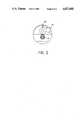
- FIG. 2is a front view of the device of FIG. 1.
- FIGS. 1 and 2there is shown in FIGS. 1 and 2 thereof an abrasive cleaning device constituting a unitary nozzle assembly, designated generally as 10.
- the unitary nozzle assembly 10includes a nozzle body 12.
- the nozzle body 12has a bore 14 connected at one end 16 to a source of high pressure water (not shown) and an opposite end 18 opening into an angled, annular cavity 20.
- Coextensive with the bore 14is a second tapered bore 22 having an end 24 connected to a source of an air-abrasive particle stream (not shown).
- An opposite end 26 of the bore 22constitutes a discharge end from the nozzle assembly 10.
- the bore 22is within sleeve 28 housed within longitudinal cavity 30 of the nozzle body 12. Th sleeve 28 is secured within the longitudinal cavity 30 by set screw 32 extending through opening 34 of the nozzle body 12 and into contact with the sleeve 28.
- a nylon washer 36defines a connection between the end 24 and a flexible hose 38 connected to the source of the air-abrasive particle stream (not shown).
- a protective sheath 40which may be of a rubberized material or rigid, metal conduit is provided over a portion of the nozzle body 12 and extends over the ends 16 and 24 of the bores 14 and 22, respectively.
- a water jet nozzle 42is positioned within the cavity 20 and communicates therein with the bore 14 connected to the source of high pressure water (not shown).
- the nozzle 42includes an annular body portion 44 having a central discharge chamber 46 opening to the outside of the nozzle assembly.
- annular insert 48At the base of the chamber 46 is an annular insert 48 having three tapered passages 50 communicating with the chamber 46 and the bore 14.
- a mixture of air and entrained abrasive particlespasses through the bore 22 and is intersected at an acute angle with high pressure water from the water nozzle 42.
- the axis of the nozzle 42is directed generally toward the surface to be abraded.
- the water issuing from the nozzle 42entrains the particles and directs them onto the surface to be cleaned.
- the protective sheath 40provides for easy handling of the nozzle assembly and protects the same from damage during use. In addition, the protective sheath protects an operator from injury should rupture of the high pressure water source occur.
- the high pressure water sourcecomprises a hose (not shown) connected to the bore 14 of the nozzle body 12.
- the unitary nozzle assembly thereof constituting the abrasive cleaning deviceprovides the required high pressure water jet or stream with entrained abrasive particles necessary for cleaning without mixing of the water and abrasive particles within the nozzle assembly to cause undue wear and deterioration thereof.
- the water and abrasive particlesare mixed outside the nozzle assembly and yet a unitary nozzle assembly is provided for this purpose to achieve the desired compactness for ease of handling during use. This is further facilitated by the use of the protective sheath in combination with the unitary nozzle assembly. In this manner, handling of the device during use is further facilitated and the nozzle assembly and associated high pressure water source are protected against damage.
- replaceable water jet nozzleenables nozzles of various configurations to be employed so that any desired configuration for the water jet may be used by merely interchanging nozzles. This replacement of the water jet nozzle may be achieved without requiring disassembly of the overall device. This facilitates field use and repair.
- this componentmay be replaced upon wear or damage with the remainder of the nozzle being retained for continued use. This contributes to the low cost construction of the nozzle assembly and its ease of use in field application.
Landscapes
- Engineering & Computer Science (AREA)
- Mechanical Engineering (AREA)
- Nozzles (AREA)
Abstract
Description
Claims (16)
Priority Applications (1)
| Application Number | Priority Date | Filing Date | Title |
|---|---|---|---|
| US07/139,574US4827680A (en) | 1987-12-30 | 1987-12-30 | Abrasive cleaning device and method |
Applications Claiming Priority (1)
| Application Number | Priority Date | Filing Date | Title |
|---|---|---|---|
| US07/139,574US4827680A (en) | 1987-12-30 | 1987-12-30 | Abrasive cleaning device and method |
Publications (1)
| Publication Number | Publication Date |
|---|---|
| US4827680Atrue US4827680A (en) | 1989-05-09 |
Family
ID=22487324
Family Applications (1)
| Application Number | Title | Priority Date | Filing Date |
|---|---|---|---|
| US07/139,574Expired - Fee RelatedUS4827680A (en) | 1987-12-30 | 1987-12-30 | Abrasive cleaning device and method |
Country Status (1)
| Country | Link |
|---|---|
| US (1) | US4827680A (en) |
Cited By (9)
| Publication number | Priority date | Publication date | Assignee | Title |
|---|---|---|---|---|
| US4913353A (en)* | 1989-03-13 | 1990-04-03 | Ingersoll-Rand Company | Nozzle apparatus having angled orifice |
| WO1991011270A1 (en)* | 1990-01-19 | 1991-08-08 | B.H.R. Group Limited | Cleaning device |
| FR2736563A1 (en)* | 1995-07-11 | 1997-01-17 | Comadur Sa | Nozzle unit for high pressure fluid cutters |
| US5664992A (en)* | 1994-06-20 | 1997-09-09 | Abclean America, Inc. | Apparatus and method for cleaning tubular members |
| US5860849A (en)* | 1997-03-25 | 1999-01-19 | Huffman Corp | Liquid abrasive jet focusing tube for making non-perpendicular cuts |
| US6224463B1 (en) | 1998-11-02 | 2001-05-01 | J.C.J. Metal Processing, Incorporated | Workpiece finishing system and method of operating same |
| US6588684B1 (en)* | 1998-12-18 | 2003-07-08 | Wesley A Staples | Fluid injector for tank cleaning |
| US20110053464A1 (en)* | 2009-09-02 | 2011-03-03 | All Coatings Elimination System Corporation | System and method for removing a coating from a substrate |
| USD640295S1 (en)* | 2010-04-01 | 2011-06-21 | IBEG, Inc. | Nozzle for a sand jet |
Citations (9)
| Publication number | Priority date | Publication date | Assignee | Title |
|---|---|---|---|---|
| FR893086A (en)* | 1943-04-03 | 1944-05-30 | Entpr Rapide De Travaux Et D E | Dust absorption device suitable for sandblasting nozzles for renovating facades in freestone, or any other material |
| GB626074A (en)* | 1946-09-04 | 1949-07-08 | Pneulec Ltd | Improvements in or relating to sand-blasting apparatus |
| US3427763A (en)* | 1966-07-18 | 1969-02-18 | Woma Maasberg Co Gmbh W | Method of treating solid surfaces |
| US3972150A (en)* | 1974-06-05 | 1976-08-03 | Bernard Eaton Hart | Guns for forming jets of particulate material |
| US4125969A (en)* | 1977-01-25 | 1978-11-21 | A. Long & Company Limited | Wet abrasion blasting |
| SU814698A1 (en)* | 1978-06-20 | 1981-03-23 | Bulkin Valentin A | Apparatus for hydraulic abrasive working of parts |
| US4341350A (en)* | 1980-09-05 | 1982-07-27 | Otto Wemmer | Chemical injection system for high pressure washers |
| US4449332A (en)* | 1979-07-31 | 1984-05-22 | Griffiths Norman J | Dispenser for a jet of liquid bearing particulate abrasive material |
| US4633623A (en)* | 1982-03-15 | 1987-01-06 | Commissariat A L'energie Atomique | Sand blasting nozzle |
- 1987
- 1987-12-30USUS07/139,574patent/US4827680A/ennot_activeExpired - Fee Related
Patent Citations (9)
| Publication number | Priority date | Publication date | Assignee | Title |
|---|---|---|---|---|
| FR893086A (en)* | 1943-04-03 | 1944-05-30 | Entpr Rapide De Travaux Et D E | Dust absorption device suitable for sandblasting nozzles for renovating facades in freestone, or any other material |
| GB626074A (en)* | 1946-09-04 | 1949-07-08 | Pneulec Ltd | Improvements in or relating to sand-blasting apparatus |
| US3427763A (en)* | 1966-07-18 | 1969-02-18 | Woma Maasberg Co Gmbh W | Method of treating solid surfaces |
| US3972150A (en)* | 1974-06-05 | 1976-08-03 | Bernard Eaton Hart | Guns for forming jets of particulate material |
| US4125969A (en)* | 1977-01-25 | 1978-11-21 | A. Long & Company Limited | Wet abrasion blasting |
| SU814698A1 (en)* | 1978-06-20 | 1981-03-23 | Bulkin Valentin A | Apparatus for hydraulic abrasive working of parts |
| US4449332A (en)* | 1979-07-31 | 1984-05-22 | Griffiths Norman J | Dispenser for a jet of liquid bearing particulate abrasive material |
| US4341350A (en)* | 1980-09-05 | 1982-07-27 | Otto Wemmer | Chemical injection system for high pressure washers |
| US4633623A (en)* | 1982-03-15 | 1987-01-06 | Commissariat A L'energie Atomique | Sand blasting nozzle |
Cited By (13)
| Publication number | Priority date | Publication date | Assignee | Title |
|---|---|---|---|---|
| US4913353A (en)* | 1989-03-13 | 1990-04-03 | Ingersoll-Rand Company | Nozzle apparatus having angled orifice |
| WO1991011270A1 (en)* | 1990-01-19 | 1991-08-08 | B.H.R. Group Limited | Cleaning device |
| US5664992A (en)* | 1994-06-20 | 1997-09-09 | Abclean America, Inc. | Apparatus and method for cleaning tubular members |
| US5885133A (en)* | 1994-06-20 | 1999-03-23 | Abclean America, Inc. | Apparatus and method for cleaning tubular members |
| FR2736563A1 (en)* | 1995-07-11 | 1997-01-17 | Comadur Sa | Nozzle unit for high pressure fluid cutters |
| US5860849A (en)* | 1997-03-25 | 1999-01-19 | Huffman Corp | Liquid abrasive jet focusing tube for making non-perpendicular cuts |
| US6224463B1 (en) | 1998-11-02 | 2001-05-01 | J.C.J. Metal Processing, Incorporated | Workpiece finishing system and method of operating same |
| US6588684B1 (en)* | 1998-12-18 | 2003-07-08 | Wesley A Staples | Fluid injector for tank cleaning |
| US20110053464A1 (en)* | 2009-09-02 | 2011-03-03 | All Coatings Elimination System Corporation | System and method for removing a coating from a substrate |
| US8353741B2 (en) | 2009-09-02 | 2013-01-15 | All Coatings Elimination System Corporation | System and method for removing a coating from a substrate |
| US8500520B2 (en) | 2009-09-02 | 2013-08-06 | All Coatings Elimination System Corporation | System and method for removing a coating from a substrate |
| USD640295S1 (en)* | 2010-04-01 | 2011-06-21 | IBEG, Inc. | Nozzle for a sand jet |
| USD640296S1 (en)* | 2010-04-01 | 2011-06-21 | IBEG, Inc. | Nozzle for a sand jet |
Similar Documents
| Publication | Publication Date | Title |
|---|---|---|
| US4333277A (en) | Combination sand-blasting and vacuum apparatus | |
| US2376616A (en) | Sandblasting apparatus | |
| US4595365A (en) | Method of and apparatus for cleaning teeth | |
| US4927079A (en) | Plural component air spray gun and method | |
| US5054249A (en) | Method and apparatus for liquid-abrasive blast cleaning | |
| JP2903249B2 (en) | Cutting head for water jet type cutting equipment | |
| US3982605A (en) | Nozzle noise silencer | |
| US4827680A (en) | Abrasive cleaning device and method | |
| EP0430858A2 (en) | Nozzle assembly for ultra-high pressure water | |
| US5765759A (en) | Removable nozzle for a sandblaster handpiece | |
| US4456181A (en) | Gas liquid mixing nozzle | |
| JPH0655452A (en) | Device and method for treating surface liable to flaw and particularly that of sculpture | |
| US4216630A (en) | Grinder apparatus with pollution control fluid dispensing means | |
| JPS5939270B2 (en) | Guns that produce jets of particulate matter and fluids | |
| EP0248638A2 (en) | Cleaning instrument using premixed abrasive liquid, a method of cleaning and an abrasive cleaning liquid | |
| JPH0728873B2 (en) | Handpiece nozzle head for tooth cleaning equipment | |
| US2439032A (en) | Shot blasting nozzle | |
| US2965312A (en) | Spray gun | |
| US4637551A (en) | Safety guard for airless spray apparatus | |
| US2597573A (en) | Spraying apparatus | |
| JPH01114267U (en) | ||
| JPH07508680A (en) | air atomizing nozzle | |
| US4243178A (en) | Air gun with safety nozzle | |
| US3256642A (en) | Underwater sandblasting gun | |
| US2405854A (en) | Gun for blasting and spraying |
Legal Events
| Date | Code | Title | Description |
|---|---|---|---|
| AS | Assignment | Owner name:TUBOSCOPE INC., A CORP. OF TEXAS,TEXAS Free format text:ASSIGNMENT OF ASSIGNORS INTEREST;ASSIGNORS:RUSHING, LARRY D.;MC FADDEN, DOUGLAS W.;SIGNING DATES FROM 19871201 TO 19871219;REEL/FRAME:004820/0643 Owner name:TUBOSCOPE INC., P.O. BOX 808, 2835 HOLMES ROAD, HO Free format text:ASSIGNMENT OF ASSIGNORS INTEREST.;ASSIGNORS:RUSHING, LARRY D.;MC FADDEN, DOUGLAS W.;REEL/FRAME:004820/0643;SIGNING DATES FROM 19871201 TO 19871219 | |
| FEPP | Fee payment procedure | Free format text:PAYOR NUMBER ASSIGNED (ORIGINAL EVENT CODE: ASPN); ENTITY STATUS OF PATENT OWNER: LARGE ENTITY | |
| AS | Assignment | Owner name:TUBOSCOPE VETCO INTERNATIONAL INC Free format text:CHANGE OF NAME;ASSIGNOR:TUBOSCOPE INC.;REEL/FRAME:006032/0271 Effective date:19920120 | |
| FPAY | Fee payment | Year of fee payment:4 | |
| FPAY | Fee payment | Year of fee payment:8 | |
| REMI | Maintenance fee reminder mailed | ||
| LAPS | Lapse for failure to pay maintenance fees | ||
| FP | Lapsed due to failure to pay maintenance fee | Effective date:20010509 | |
| STCH | Information on status: patent discontinuation | Free format text:PATENT EXPIRED DUE TO NONPAYMENT OF MAINTENANCE FEES UNDER 37 CFR 1.362 |