US4827196A - Motor control arrangement - Google Patents
Motor control arrangementDownload PDFInfo
- Publication number
- US4827196A US4827196AUS07/128,409US12840987AUS4827196AUS 4827196 AUS4827196 AUS 4827196AUS 12840987 AUS12840987 AUS 12840987AUS 4827196 AUS4827196 AUS 4827196A
- Authority
- US
- United States
- Prior art keywords
- current
- motor
- control arrangement
- control
- commutation
- Prior art date
- Legal status (The legal status is an assumption and is not a legal conclusion. Google has not performed a legal analysis and makes no representation as to the accuracy of the status listed.)
- Expired - Lifetime
Links
- 238000004804windingMethods0.000claimsdescription18
- 239000011159matrix materialSubstances0.000claimsdescription14
- 230000005693optoelectronicsEffects0.000claimsdescription3
- 230000008878couplingEffects0.000claims1
- 238000010168coupling processMethods0.000claims1
- 238000005859coupling reactionMethods0.000claims1
- 230000000873masking effectEffects0.000claims1
- 238000012163sequencing techniqueMethods0.000claims1
- 238000002955isolationMethods0.000description6
- 230000005355Hall effectEffects0.000description4
- 238000010586diagramMethods0.000description4
- 230000001276controlling effectEffects0.000description3
- 230000000694effectsEffects0.000description3
- 238000000034methodMethods0.000description3
- 238000012986modificationMethods0.000description2
- 230000004048modificationEffects0.000description2
- 230000001052transient effectEffects0.000description2
- 238000006243chemical reactionMethods0.000description1
- 230000001934delayEffects0.000description1
- 238000012544monitoring processMethods0.000description1
- 230000001105regulatory effectEffects0.000description1
- 230000035945sensitivityEffects0.000description1
- 239000007787solidSubstances0.000description1
Images

Classifications
- H—ELECTRICITY
- H02—GENERATION; CONVERSION OR DISTRIBUTION OF ELECTRIC POWER
- H02P—CONTROL OR REGULATION OF ELECTRIC MOTORS, ELECTRIC GENERATORS OR DYNAMO-ELECTRIC CONVERTERS; CONTROLLING TRANSFORMERS, REACTORS OR CHOKE COILS
- H02P6/00—Arrangements for controlling synchronous motors or other dynamo-electric motors using electronic commutation dependent on the rotor position; Electronic commutators therefor
- H02P6/14—Electronic commutators
- H—ELECTRICITY
- H02—GENERATION; CONVERSION OR DISTRIBUTION OF ELECTRIC POWER
- H02P—CONTROL OR REGULATION OF ELECTRIC MOTORS, ELECTRIC GENERATORS OR DYNAMO-ELECTRIC CONVERTERS; CONTROLLING TRANSFORMERS, REACTORS OR CHOKE COILS
- H02P6/00—Arrangements for controlling synchronous motors or other dynamo-electric motors using electronic commutation dependent on the rotor position; Electronic commutators therefor
- H02P6/28—Arrangements for controlling current
Definitions
- This inventionrelates to a motor control arrangement and in particular to a motor control arrangement for a brushless dc motor used in a centrifuge instrument.
- Brushless dc motorsare known in the art. Such motors are available from a wide variety of sources, such as, for example, Electric Indicator Company, Incorporated of Norwalk, Conn. Such a motor has a rotating element that carries an array of permanent magnets. A stationary armature formed of multiple phase windings surrounds the rotor. The windings are connected via a switching matrix to positive and negative busses. For a given direction of rotation the position of the permanent magnets on the rotor determines which of the switches are closed with respect to the positive and negative busses. The actual control signals which open and close the appropriate switches are generated by suitable current control and commutation control arrangements in a manner well known to those skilled in the art.
- control elementsare connected to the same voltage reference point and share common current paths with the motor.
- rapid switching of relatively high currents at relatively high voltagesare exacerbated when a brushless dc motor is used to drive a centrifuge instrument because of the magnitude of the currents and voltages required to deliver the amount of power necessary to achieve the sustain centrifuge rotor speed.
- an electrically noisy environmentis created in which the control elements must operate.
- the present inventionrelates to a control system for a brushless dc electric motor of the type in which the torque output of the motor is directly proportional to the current applied thereto.
- the motoris connectable to positive and negative high voltage busses via a switching matrix.
- the motorhas stationary armature windings with a plurality of phases and a rotating element with permanent magnets mounted thereon. Position sensors for sensing the position of the rotating element with respect to the armature windings and a sensor for sensing the current flow through the phases of the motor are provided.
- a current control arrangement responsive to the current sensordirectly controls the torque output of the motor by controlling the current applied thereto.
- a low voltage commutation control arrangementresponsive to the current control and to the position sensors for producing commutation control signals sequences the application of current to the appropriate phases of the windings by opening and closing the appropriate high voltage switches in accordance with the position of the rotating element.
- a dielectric interfacecouples the commutation control signals to the high voltage switches connected to the positive bus.
- both the commutation control arrangement and the current control arrangementare connected to a different voltage reference and have no common current paths with the motor.
- the connectionis effected in such a way that these elements operate in a lower electrical noise environment.
- the voltage reference for the commutation control and the current controlis chassis ground potential.
- dielectric interfacesare disposed between all of the high voltage switches and the commutation control such that all commutation control signals are coupled to all of the switches via the interfaces.
- the commutation control signalsare indirectly applied to the switches connected to the high voltage bus and to the low voltage bus.
- the dielectric interfacestake the form of opto-electronic devices.
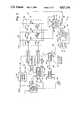
- FIG. 1is a schematic diagram of the motor control arrangement in accordance with the prior art.
- FIG. 2is a schematic diagram of a motor control arrangement in accordance with the present invention.
- a brushless dc motordiagrammatically indicated at reference character 12, such as that manufactured and sold by Electric Indicator Company, Incorporated of Norwalk, Conn., includes a rotating element 16 and a stationary armature 20.
- the rotating element 16has a shaft 21 which carries a plurality of permanent magnets 22.
- the magnets 22define an array of magnetic poles. Any convenient even number of such magnetic poles may be defined, with the typical number of magnetic poles being four.
- the armature 20comprises a multiphase winding 24 which may be interconnected in either a wye or delta configuraton or some other desirable arrangement.
- the phases of the winding 24are mechanically arranged circumferentially about the rotating element 16.
- the motor 12exhibits a torque to applied current characteristic that is substantially linear. That is, the torque output of the motor 12 is directly proportional to the current applied to the armature winding 24.
- the phases of the winding 24are connectable to positive and negative electrical busses 28 and 30, respectively. Typically a voltage range of fifty to three hundred fifty volts dc is defined between the busses 28, 30.
- the busses 28, 30are connected through a switching matrix 34 to a source of dc power such as that produced at the output terminals of a variable dc voltage source 38 in a manner known to those skilled in the art.
- the switching matrix 34is formed of a plurality of legs each of which includes a switch element 40H and 40L respectively connected to the high voltage bus 28 and to the low voltage bus 30. The number of legs corresponds to the number of phases in the winding 24.
- the motor winding 24is shown to include three phases 24a, 24B and 24C (shown diagrammatically) and thus the switching matrix 34 includes legs 34A, 34B and 34C.
- a sensor 44such as a resistive element or a current transformer or a Hall Effect device, is connected in a position to monitor the magnitude of the current flowing through any combination of phases 24A, 24B, 24C of the motor 12. It is common practice to connect the sensor 44 between the negative bus 30 and the switches 40L, as shown in FIG. 1.
- An array of position sensors 48A, 48B, and 48Cis provided to sense the angular position of the rotor 16 with respect to the armature winding 20 and to provide a signal indicative thereof on respective output lines 50A, 50B and 50C.
- the position sensorstake the form of Hall Effect devices.
- An auxiliary magnet structure 54is disposed on the shaft 21 of the rotating element 16 to actuate the sensors 48A, 48B, 48C.
- a current control arrangement, or current controller, 60is responsive to the current sensor 44 through the line 45 for directly controlling the current applied to the motor and thus controlling the torque output produced thereby.
- the control output from the current controller 60 on the line 62represents the time duration during which a given one or more of the switches 40H or 40L in a given one or more of the legs 34A, 34B or 34C is to be closed.
- the time durationmay be varied using conventionally known pulse width modulation techniques such as those disclosed in Principles of Solid State Power Conversion, R. E. Tartar, H. W. Sams and Co., Inc. (1985). The pertinent portions of this text, Sections 8 and 9, are hereby incorporated by reference.
- the control systemfurther includes a commutation control arrangement 68 responsive to the signals from the position sensors 48A, 48B, 48C on the lines 50A, 50B and 50C, respectively, and to the signal from the current controller 60 on the line 62, and to external control signals typically supplied from a programmable source and applied over a line 64 to generate commutation control signals on lines 70A, 70B and 70C and lines 72A, 72B, and 72C.
- These commutation control signalssequence the closure of the appropriate switches 40H and 40L in the appropriate legs 34A, 34B and 34C to thus provide current through the associated phases of the winding 24.
- the lines 70A, 70B and 70Care connected to the switches 40H in each of the legs 34A, 34B and 34C, respectively, while the lines 72A, 72B and 72C are connected to the switches 40L, in each of the legs 34A, 34B and 34C, respectively.
- a dielectric isolation interface 74A, 74B and 74C illustrated by a single functional block in FIG. 1is respectively provided in each of the lines 70A, 70B and 70C.
- Suitable for use as the interface 74is an opto-electronic coupler such as that manufactured and sold by General Electric as model H11AV2.
- the interface 74may take the form of a pulse transformer such as that manufactured and sold by Coilcraft Inc. of Cary, Ill. as model number SD250-3.
- the switches 40L in each leg 34A, 34B and 34Care operated with reference to the negative electrical bus 30 an interface is not required.
- a voltage regulator 78provides a regulated, relatively low voltage (on the order of plus/minus five to fifteen volts) to power the components in the commutation control arrangement 68 and the current control arrangement 60.
- the regulator 78typically has a dielectric isolation boundary between its high voltage ac inputs and its low voltage dc outputs.
- FIG. 2is a schematic diagram similar to FIG. 1 showing a motor control arrangement 10' in accordance with the present invention which permits operation at both high and low levels of motor current.
- the commutation control arrangement 68 and the current control arrangement 60are connected to a voltage reference 80 different from the voltage reference 79 of the motor 12 and the switching matrix 34.
- the control elements 60 and 68do not share a common current path with the motor 12 and are thus not subjected to the high transient-induced electrical noise present in the switching matrix 34 and the motor 12.
- the control arrangements 60 and 68are thus, in effect, operated in an environment having lower electrical noise.
- the reference potential for the control arrangements 60 and 68is the chassis ground. Other convenient reference potentials may be selected against which to reference the voltages for the control arrangements 60 and 68, so long as a common current path with these elements and the motor and the switching matrix 34 is not defined.
- the current sensor 44' used in FIG. 2is a Hall Effect sensor such as that sold by Microswitch, a division of Honeywell, which preferably combines both average and peak motor current sensing techniques to permit real time monitoring of actual motor current sufficient to accurately control the current at the operating frequency selected and provides a dielectrically isolated indication of the motor current.
- the sensor 44'is implemented with an added current transformer winding around the magnetic core of the Hall Effect device. This technique provides DC, low frequency and high frequency isolated sensing capabilities in one device.
- the network of the present inventionmay thus be viewed as having an interface indicated by the dot-dash line 82 on one side 86 of which--the side on which the control arrangements 60, 68 reside--relatively low electrical noise exists as compared to the the opposite side 88 having the relatively higher electrical noise.
- the interfaces 74'similar to the interfaces 74 discussed above, are necessary to connect the commutation control signal outputs from the commutation control arrangement 68 on the lines 72A, 72B and 72C to the associated switches 40L in the legs 34A, 34B and 34C of the matrix 34. Because of the lower electrical noise level on the side 86, the current controller 60 can successfully monitor and control low motor current levels which were previously masked by the high level of electrical noise. The dynamic range of current controller 60 is thereby enhanced due to an increased signal to noise ratio. The degree of enhancement can be increased by increasing the frequency of the pulse width modulation used in the current controller 60.
- Preferably operating frequencies on the order of twenty kilohertzare used. It should be understood however that subject to practical limitations imposed by devices 40H, 40L used in the switching matrix 34, the tighter the control of current sought the higher is the frequency of operation to be used. Enhancements on the order of twenty times those available with a system as described in FIG. 1 may be achieved.
- the motor control arrangmenet 10'accomplishes stable operation throughout the range of desired motor current from fifty milliamperes to twenty amperes, a dynamic range on the order of four hundred to one (400:1).
- the dielectric isolation interfaces 74 and 74'must operate with a propagation delay short enough to permit a stable control loop.
- the pulse width modulated signal on the line 62is applied simultaneously to the appropriate switches 40H and 40L through the dielectric isolation interfaces 74 and 74' respectively.
- the propagation delays of each of the dielectric isolation interfaces 74A, 74B, 74Cshould be one to ten times greater than the propagation delay of the associated dielectric isolation interfaces 74'A, 74'B, 74'C, respectively.
- the preferred delay times on the order of four hundred nanoseconds or lessshould be used.
Landscapes
- Engineering & Computer Science (AREA)
- Power Engineering (AREA)
- Control Of Motors That Do Not Use Commutators (AREA)
Abstract
Description
Claims (4)
Priority Applications (6)
| Application Number | Priority Date | Filing Date | Title |
|---|---|---|---|
| US07/128,409US4827196A (en) | 1987-12-03 | 1987-12-03 | Motor control arrangement |
| DE3889430TDE3889430T2 (en) | 1987-12-03 | 1988-11-30 | Device for controlling an engine. |
| EP88119932AEP0318938B1 (en) | 1987-12-03 | 1988-11-30 | Motor control arrangement |
| CA000584743ACA1289187C (en) | 1987-12-03 | 1988-12-01 | Motor control arrangement |
| IE359388AIE64827B1 (en) | 1987-12-03 | 1988-12-01 | Motor control arrangement |
| JP63304266AJP2545126B2 (en) | 1987-12-03 | 1988-12-02 | Motor control device |
Applications Claiming Priority (1)
| Application Number | Priority Date | Filing Date | Title |
|---|---|---|---|
| US07/128,409US4827196A (en) | 1987-12-03 | 1987-12-03 | Motor control arrangement |
Publications (1)
| Publication Number | Publication Date |
|---|---|
| US4827196Atrue US4827196A (en) | 1989-05-02 |
Family
ID=22435243
Family Applications (1)
| Application Number | Title | Priority Date | Filing Date |
|---|---|---|---|
| US07/128,409Expired - LifetimeUS4827196A (en) | 1987-12-03 | 1987-12-03 | Motor control arrangement |
Country Status (6)
| Country | Link |
|---|---|
| US (1) | US4827196A (en) |
| EP (1) | EP0318938B1 (en) |
| JP (1) | JP2545126B2 (en) |
| CA (1) | CA1289187C (en) |
| DE (1) | DE3889430T2 (en) |
| IE (1) | IE64827B1 (en) |
Cited By (16)
| Publication number | Priority date | Publication date | Assignee | Title |
|---|---|---|---|---|
| US5032773A (en)* | 1989-08-07 | 1991-07-16 | Siemens Aktiengsellschaft | Drive system with a drive motor |
| US5059875A (en)* | 1989-12-11 | 1991-10-22 | Salme William A De | Motor and controller |
| US5220258A (en)* | 1990-06-18 | 1993-06-15 | Papst-Motoren Gmbh & Co. Kg | Drive circuit for a brushless direct-current motor |
| US5235864A (en)* | 1990-12-21 | 1993-08-17 | E. I. Du Pont De Nemours And Company | Centrifuge rotor identification system based on rotor velocity |
| US5317245A (en)* | 1992-10-29 | 1994-05-31 | Mfm Technology, Inc. | Brushless DC motor control network |
| US5343129A (en)* | 1990-06-18 | 1994-08-30 | Papst Licensing Gmbh | Drive circuit for a brushless direct-current motor |
| WO1998019386A1 (en)* | 1996-10-31 | 1998-05-07 | Mfm Technology, Inc. | Two-wire brushless dc motor control system |
| US5929577A (en)* | 1995-10-13 | 1999-07-27 | Unitrode Corporation | Brushless DC motor controller |
| US6169378B1 (en) | 1996-06-07 | 2001-01-02 | Papst Motoren Gmbh & Co. Kg | Electronically commutated motor with galvanically separate user interface circuit |
| US20010012814A1 (en)* | 1999-07-12 | 2001-08-09 | May David F. | Motor driven centrifugal filter |
| US20020195979A1 (en)* | 2001-06-20 | 2002-12-26 | Nissan Motor Co., Ltd. | Motor controller and control method thereof |
| US8198850B2 (en)* | 2008-01-25 | 2012-06-12 | Control Techniques Ltd. | DC motor drive |
| US20120202649A1 (en)* | 2011-02-07 | 2012-08-09 | Clarkson University | Pedal generator electric bicycle |
| US8421368B2 (en) | 2007-07-31 | 2013-04-16 | Lsi Industries, Inc. | Control of light intensity using pulses of a fixed duration and frequency |
| US8604709B2 (en) | 2007-07-31 | 2013-12-10 | Lsi Industries, Inc. | Methods and systems for controlling electrical power to DC loads |
| US8903577B2 (en) | 2009-10-30 | 2014-12-02 | Lsi Industries, Inc. | Traction system for electrically powered vehicles |
Families Citing this family (4)
| Publication number | Priority date | Publication date | Assignee | Title |
|---|---|---|---|---|
| DE4019338A1 (en)* | 1990-06-18 | 1991-12-19 | Papst Motoren Gmbh & Co Kg | DRIVER CIRCUIT FOR A BRUSHLESS DC MOTOR |
| US5045988A (en)* | 1990-07-31 | 1991-09-03 | Eaton Corporation | Isolated adjustable frequency AC inverter control |
| US6008602A (en)* | 1996-06-07 | 1999-12-28 | Papst-Motoren Gmbh & Co. Kg | Arrangement with an electronically commutated motor |
| DE20105050U1 (en)* | 2000-05-27 | 2001-06-28 | Papst-Motoren GmbH & Co. KG, 78112 St Georgen | Motor arrangement |
Citations (32)
| Publication number | Priority date | Publication date | Assignee | Title |
|---|---|---|---|---|
| US2512325A (en)* | 1949-05-25 | 1950-06-20 | Gen Electric | Hall effect commutating apparatus |
| US3083314A (en)* | 1963-03-26 | figure | ||
| US3159777A (en)* | 1961-12-15 | 1964-12-01 | Gen Electric | Direct current motor |
| US3165685A (en)* | 1962-04-18 | 1965-01-12 | Gen Electric | Solid-state commutator direct current motor employing hall effect elements |
| US3262040A (en)* | 1963-09-23 | 1966-07-19 | Sorvall Inc Ivan | Speed control system for centrifuge motors and the like |
| US3419782A (en)* | 1965-09-20 | 1968-12-31 | Gen Motors Corp | Direct current commutation system for brushless electrical motors |
| US3476997A (en)* | 1966-03-04 | 1969-11-04 | Licentia Gmbh | Brushless d.c. motor control |
| US3631272A (en)* | 1969-04-04 | 1971-12-28 | Daiko Electronics Ind Co Ltd | Dc electric motor using hall elements |
| US3667019A (en)* | 1970-10-12 | 1972-05-30 | Gen Motors Corp | Control circuit for adjusting and regulating the speed of a brushless direct current motor responsive to voltages induced in the armature windings |
| US3720865A (en)* | 1969-04-29 | 1973-03-13 | Thomson Csf | Brushless d.c. motor |
| US3760392A (en)* | 1972-05-15 | 1973-09-18 | Allis Chalmers | Capacitive position sensor |
| US3775648A (en)* | 1971-08-04 | 1973-11-27 | Garrett Corp | Brushless motor control |
| US3778691A (en)* | 1971-08-20 | 1973-12-11 | Siemens Ag | Control circuit for an electric machine having an electronic commutator |
| US3783359A (en)* | 1971-12-23 | 1974-01-01 | Bendix Corp | Brushless d. c. motor using hall generators for commutation |
| US3988654A (en)* | 1973-12-21 | 1976-10-26 | Hitachi, Ltd. | Miniature brushless motor |
| US4167691A (en)* | 1977-01-20 | 1979-09-11 | Danfoss A/S | Control arrangement for a brushless motor |
| US4169990A (en)* | 1974-06-24 | 1979-10-02 | General Electric Company | Electronically commutated motor |
| US4260938A (en)* | 1975-02-28 | 1981-04-07 | Lucas Industries Limited | Control circuits for electrically driven vehicles |
| US4311933A (en)* | 1979-08-27 | 1982-01-19 | North American Philips Corporation | Brushless direct current motor |
| US4494057A (en)* | 1981-12-05 | 1985-01-15 | Kabushiki Kaisha Morita Seisakusho | Speed control system for small medical motors |
| US4551715A (en)* | 1984-04-30 | 1985-11-05 | Beckman Instruments, Inc. | Tachometer and rotor identification apparatus for centrifuges |
| US4554492A (en)* | 1983-12-15 | 1985-11-19 | Baxter Travenol Laboratories, Inc. | Motor control system |
| US4564795A (en)* | 1981-12-21 | 1986-01-14 | Beckman Instruments, Inc. | Motor speed control system |
| US4581711A (en)* | 1982-04-01 | 1986-04-08 | Kabushiki Kaisha Okuma Tekkosho | Monitoring system for motors |
| US4605885A (en)* | 1984-08-07 | 1986-08-12 | Mitsubishi Denki Kabushiki Kaisha | Method of controlling rotation speed of motor |
| US4616162A (en)* | 1985-03-18 | 1986-10-07 | General Motors Corporation | Speed selection control for vehicle mounted electric accessory motor |
| US4629980A (en)* | 1985-05-28 | 1986-12-16 | International Business Machines Corporation | Testing limits of speed variations in motors |
| US4656402A (en)* | 1985-02-13 | 1987-04-07 | Nippondenso Co., Ltd. | Electric motor control apparatus |
| US4661750A (en)* | 1984-08-22 | 1987-04-28 | Brother Kogyo Kabushiki Kaisha | Device for controlling DC motor |
| US4680513A (en)* | 1986-08-11 | 1987-07-14 | Harbor Branch Oceanographic Institute Inc. | Electric motor reversing control devices |
| US4700117A (en)* | 1985-05-31 | 1987-10-13 | Beckman Instruments, Inc. | Centrifuge overspeed protection and imbalance detection system |
| US4777382A (en)* | 1987-06-19 | 1988-10-11 | Allied-Signal, Inc. | Pulse width logic/power isolation circuit |
Family Cites Families (6)
| Publication number | Priority date | Publication date | Assignee | Title |
|---|---|---|---|---|
| US4363061A (en)* | 1980-06-10 | 1982-12-07 | Westinghouse Electric Corp. | Electric motor and transformer load sensing technique |
| JPS59149497U (en)* | 1983-03-25 | 1984-10-05 | 愛知電機株式会社 | Rotor position detection device for brushless DC motors |
| US4544868A (en)* | 1984-07-20 | 1985-10-01 | General Motors Corporation | Brushless DC motor controller |
| JPS62126869A (en)* | 1985-11-27 | 1987-06-09 | Fanuc Ltd | Composite power module element |
| FR2596219B1 (en)* | 1986-03-21 | 1988-04-22 | Elf Aquitaine | MOTOR SWITCHING CONTROL CIRCUIT AND APPLICATION TO SPEED VARIATION OF THE CONTROL CIRCUIT |
| JPS6339485A (en)* | 1986-07-30 | 1988-02-19 | Mitsubishi Electric Corp | Position sensing circuit for dc brushless motor |
- 1987
- 1987-12-03USUS07/128,409patent/US4827196A/ennot_activeExpired - Lifetime
- 1988
- 1988-11-30DEDE3889430Tpatent/DE3889430T2/ennot_activeExpired - Fee Related
- 1988-11-30EPEP88119932Apatent/EP0318938B1/ennot_activeExpired - Lifetime
- 1988-12-01IEIE359388Apatent/IE64827B1/ennot_activeIP Right Cessation
- 1988-12-01CACA000584743Apatent/CA1289187C/ennot_activeExpired - Lifetime
- 1988-12-02JPJP63304266Apatent/JP2545126B2/ennot_activeExpired - Lifetime
Patent Citations (32)
| Publication number | Priority date | Publication date | Assignee | Title |
|---|---|---|---|---|
| US3083314A (en)* | 1963-03-26 | figure | ||
| US2512325A (en)* | 1949-05-25 | 1950-06-20 | Gen Electric | Hall effect commutating apparatus |
| US3159777A (en)* | 1961-12-15 | 1964-12-01 | Gen Electric | Direct current motor |
| US3165685A (en)* | 1962-04-18 | 1965-01-12 | Gen Electric | Solid-state commutator direct current motor employing hall effect elements |
| US3262040A (en)* | 1963-09-23 | 1966-07-19 | Sorvall Inc Ivan | Speed control system for centrifuge motors and the like |
| US3419782A (en)* | 1965-09-20 | 1968-12-31 | Gen Motors Corp | Direct current commutation system for brushless electrical motors |
| US3476997A (en)* | 1966-03-04 | 1969-11-04 | Licentia Gmbh | Brushless d.c. motor control |
| US3631272A (en)* | 1969-04-04 | 1971-12-28 | Daiko Electronics Ind Co Ltd | Dc electric motor using hall elements |
| US3720865A (en)* | 1969-04-29 | 1973-03-13 | Thomson Csf | Brushless d.c. motor |
| US3667019A (en)* | 1970-10-12 | 1972-05-30 | Gen Motors Corp | Control circuit for adjusting and regulating the speed of a brushless direct current motor responsive to voltages induced in the armature windings |
| US3775648A (en)* | 1971-08-04 | 1973-11-27 | Garrett Corp | Brushless motor control |
| US3778691A (en)* | 1971-08-20 | 1973-12-11 | Siemens Ag | Control circuit for an electric machine having an electronic commutator |
| US3783359A (en)* | 1971-12-23 | 1974-01-01 | Bendix Corp | Brushless d. c. motor using hall generators for commutation |
| US3760392A (en)* | 1972-05-15 | 1973-09-18 | Allis Chalmers | Capacitive position sensor |
| US3988654A (en)* | 1973-12-21 | 1976-10-26 | Hitachi, Ltd. | Miniature brushless motor |
| US4169990A (en)* | 1974-06-24 | 1979-10-02 | General Electric Company | Electronically commutated motor |
| US4260938A (en)* | 1975-02-28 | 1981-04-07 | Lucas Industries Limited | Control circuits for electrically driven vehicles |
| US4167691A (en)* | 1977-01-20 | 1979-09-11 | Danfoss A/S | Control arrangement for a brushless motor |
| US4311933A (en)* | 1979-08-27 | 1982-01-19 | North American Philips Corporation | Brushless direct current motor |
| US4494057A (en)* | 1981-12-05 | 1985-01-15 | Kabushiki Kaisha Morita Seisakusho | Speed control system for small medical motors |
| US4564795A (en)* | 1981-12-21 | 1986-01-14 | Beckman Instruments, Inc. | Motor speed control system |
| US4581711A (en)* | 1982-04-01 | 1986-04-08 | Kabushiki Kaisha Okuma Tekkosho | Monitoring system for motors |
| US4554492A (en)* | 1983-12-15 | 1985-11-19 | Baxter Travenol Laboratories, Inc. | Motor control system |
| US4551715A (en)* | 1984-04-30 | 1985-11-05 | Beckman Instruments, Inc. | Tachometer and rotor identification apparatus for centrifuges |
| US4605885A (en)* | 1984-08-07 | 1986-08-12 | Mitsubishi Denki Kabushiki Kaisha | Method of controlling rotation speed of motor |
| US4661750A (en)* | 1984-08-22 | 1987-04-28 | Brother Kogyo Kabushiki Kaisha | Device for controlling DC motor |
| US4656402A (en)* | 1985-02-13 | 1987-04-07 | Nippondenso Co., Ltd. | Electric motor control apparatus |
| US4616162A (en)* | 1985-03-18 | 1986-10-07 | General Motors Corporation | Speed selection control for vehicle mounted electric accessory motor |
| US4629980A (en)* | 1985-05-28 | 1986-12-16 | International Business Machines Corporation | Testing limits of speed variations in motors |
| US4700117A (en)* | 1985-05-31 | 1987-10-13 | Beckman Instruments, Inc. | Centrifuge overspeed protection and imbalance detection system |
| US4680513A (en)* | 1986-08-11 | 1987-07-14 | Harbor Branch Oceanographic Institute Inc. | Electric motor reversing control devices |
| US4777382A (en)* | 1987-06-19 | 1988-10-11 | Allied-Signal, Inc. | Pulse width logic/power isolation circuit |
Non-Patent Citations (2)
| Title |
|---|
| Tartar, R. E., "Principles of Solid State Power Conversion", H. W. Sams & Co., Inc. (1985), Chapters 8 and 9. |
| Tartar, R. E., Principles of Solid State Power Conversion , H. W. Sams & Co., Inc. (1985), Chapters 8 and 9.* |
Cited By (20)
| Publication number | Priority date | Publication date | Assignee | Title |
|---|---|---|---|---|
| US5032773A (en)* | 1989-08-07 | 1991-07-16 | Siemens Aktiengsellschaft | Drive system with a drive motor |
| US5059875A (en)* | 1989-12-11 | 1991-10-22 | Salme William A De | Motor and controller |
| US5220258A (en)* | 1990-06-18 | 1993-06-15 | Papst-Motoren Gmbh & Co. Kg | Drive circuit for a brushless direct-current motor |
| US5343129A (en)* | 1990-06-18 | 1994-08-30 | Papst Licensing Gmbh | Drive circuit for a brushless direct-current motor |
| US5589745A (en)* | 1990-06-18 | 1996-12-31 | Papst Licensing Gmbh | Drive circuit for a brushless direct-current motor |
| US5598073A (en)* | 1990-06-18 | 1997-01-28 | Papst Licensing Gmbh | Drive circuit for a brushless direct-current motor |
| US5235864A (en)* | 1990-12-21 | 1993-08-17 | E. I. Du Pont De Nemours And Company | Centrifuge rotor identification system based on rotor velocity |
| US5317245A (en)* | 1992-10-29 | 1994-05-31 | Mfm Technology, Inc. | Brushless DC motor control network |
| US5929577A (en)* | 1995-10-13 | 1999-07-27 | Unitrode Corporation | Brushless DC motor controller |
| US6169378B1 (en) | 1996-06-07 | 2001-01-02 | Papst Motoren Gmbh & Co. Kg | Electronically commutated motor with galvanically separate user interface circuit |
| US5773941A (en)* | 1996-10-31 | 1998-06-30 | Mfm Technology, Inc. | Two-wire brushless DC motor control system |
| WO1998019386A1 (en)* | 1996-10-31 | 1998-05-07 | Mfm Technology, Inc. | Two-wire brushless dc motor control system |
| US20010012814A1 (en)* | 1999-07-12 | 2001-08-09 | May David F. | Motor driven centrifugal filter |
| US20020195979A1 (en)* | 2001-06-20 | 2002-12-26 | Nissan Motor Co., Ltd. | Motor controller and control method thereof |
| US6781334B2 (en)* | 2001-06-20 | 2004-08-24 | Nissan Motor Co., Ltd. | Motor controller and control method thereof |
| US8421368B2 (en) | 2007-07-31 | 2013-04-16 | Lsi Industries, Inc. | Control of light intensity using pulses of a fixed duration and frequency |
| US8604709B2 (en) | 2007-07-31 | 2013-12-10 | Lsi Industries, Inc. | Methods and systems for controlling electrical power to DC loads |
| US8198850B2 (en)* | 2008-01-25 | 2012-06-12 | Control Techniques Ltd. | DC motor drive |
| US8903577B2 (en) | 2009-10-30 | 2014-12-02 | Lsi Industries, Inc. | Traction system for electrically powered vehicles |
| US20120202649A1 (en)* | 2011-02-07 | 2012-08-09 | Clarkson University | Pedal generator electric bicycle |
Also Published As
| Publication number | Publication date |
|---|---|
| JP2545126B2 (en) | 1996-10-16 |
| EP0318938A2 (en) | 1989-06-07 |
| IE64827B1 (en) | 1995-09-06 |
| DE3889430D1 (en) | 1994-06-09 |
| EP0318938B1 (en) | 1994-05-04 |
| DE3889430T2 (en) | 1994-08-25 |
| CA1289187C (en) | 1991-09-17 |
| EP0318938A3 (en) | 1989-10-25 |
| JPH01264589A (en) | 1989-10-20 |
| IE883593L (en) | 1989-06-03 |
Similar Documents
| Publication | Publication Date | Title |
|---|---|---|
| US4827196A (en) | Motor control arrangement | |
| US4364005A (en) | Brushless tachometer generator | |
| US4262237A (en) | Commutatorless direct current motor drive system | |
| EP0123807A2 (en) | Driving and detection of back EMF in permanent magnet step motors | |
| TW328190B (en) | Control device of brushless motor and method of fault detection and air conditioner | |
| ATE84924T1 (en) | COMMUTATION CIRCUIT FOR A COLLECTORLESS DC MOTOR. | |
| EP1052766B1 (en) | Method and device for controlling electric motors of the brushless direct-current type, particularly for moving the weft winding arm in weft feeders for weaving looms | |
| US4418303A (en) | DC Motor control circuit | |
| CA2187991A1 (en) | Method and Apparatus for Controlling Static Electronic Components for Phase Switching in a Three-Phase Brushless Electric Motor | |
| ES8404581A1 (en) | A circuit and a method for processing amplitude and phase variable multiphase signals which are required as current or voltage reference to drive synchronous motors. | |
| EP0539335B1 (en) | A linear feedback control circuit for a half-wave polyphase brushless motor | |
| EP0271125B1 (en) | Brushless d.c. motor and switching device for use in such a d.c. motor | |
| US5126647A (en) | Pulse by pulse current limit and phase current monitor for a pulse width modulated inverter | |
| JPS57160386A (en) | Position detecting method for brushless direct current motor | |
| Kavanagh et al. | Innovative current sensing for brushless dc drives | |
| US4647829A (en) | Means and method for stepping motor stabilization | |
| SU1394321A1 (en) | Device for protecting three-phase asynchronous motor supplied by frequency converter against operating in two phases | |
| SU1037403A1 (en) | Method and apparatus for controlling induction electric motor | |
| KR0123002Y1 (en) | Braking circuit of an induction motor | |
| SU1714782A1 (en) | Dc electric drive unit | |
| SU712969A1 (en) | Symistor three-phase circuit switching device | |
| SU1181070A1 (en) | Thyratron motor | |
| JPH01209988A (en) | brushless motor | |
| SU1051638A1 (en) | Device for one-phase short-circuit protection of mains line | |
| SU1686637A1 (en) | Rectifier controlled motor for magnetic recording equipment |
Legal Events
| Date | Code | Title | Description |
|---|---|---|---|
| AS | Assignment | Owner name:E. I. DU PONT DE NEMOURS AND COMPANY, WILMINGTON, Free format text:ASSIGNMENT OF ASSIGNORS INTEREST.;ASSIGNOR:ODELL, DANIEL M. C.;REEL/FRAME:004835/0295 Effective date:19871120 Owner name:E. I. DU PONT DE NEMOURS AND COMPANY, A CORP. OF Free format text:ASSIGNMENT OF ASSIGNORS INTEREST;ASSIGNOR:ODELL, DANIEL M. C.;REEL/FRAME:004835/0295 Effective date:19871120 | |
| STCF | Information on status: patent grant | Free format text:PATENTED CASE | |
| FPAY | Fee payment | Year of fee payment:4 | |
| FEPP | Fee payment procedure | Free format text:PAYOR NUMBER ASSIGNED (ORIGINAL EVENT CODE: ASPN); ENTITY STATUS OF PATENT OWNER: LARGE ENTITY | |
| AS | Assignment | Owner name:SORVALL PRODUCTS, L.P., CONNECTICUT Free format text:ASSIGNMENT OF ASSIGNORS INTEREST;ASSIGNOR:E. I. DUPONT DE NEMOURS AND COMPANY;REEL/FRAME:008048/0947 Effective date:19960628 | |
| AS | Assignment | Owner name:BANK OF AMERICA ILLINOIS, ILLINOIS Free format text:SECURITY INTEREST;ASSIGNOR:SORVALL PRODUCTS, L.P.;REEL/FRAME:008067/0516 Effective date:19960628 | |
| FEPP | Fee payment procedure | Free format text:PAT HOLDER CLAIMS SMALL ENTITY STATUS - SMALL BUSINESS (ORIGINAL EVENT CODE: SM02); ENTITY STATUS OF PATENT OWNER: LARGE ENTITY | |
| REMI | Maintenance fee reminder mailed | ||
| FPAY | Fee payment | Year of fee payment:8 | |
| SULP | Surcharge for late payment | ||
| AS | Assignment | Owner name:FLEET CAPITAL CORPORATION, AS ADMINISTRATIVE AGENT Free format text:SECURITY INTEREST;ASSIGNOR:SORVALL PRODUCTS, L.P.;REEL/FRAME:009187/0962 Effective date:19980430 | |
| FEPP | Fee payment procedure | Free format text:PAT HLDR NO LONGER CLAIMS SMALL ENT STAT AS SMALL BUSINESS (ORIGINAL EVENT CODE: LSM2); ENTITY STATUS OF PATENT OWNER: LARGE ENTITY Free format text:PAYER NUMBER DE-ASSIGNED (ORIGINAL EVENT CODE: RMPN); ENTITY STATUS OF PATENT OWNER: LARGE ENTITY | |
| FEPP | Fee payment procedure | Free format text:PAYOR NUMBER ASSIGNED (ORIGINAL EVENT CODE: ASPN); ENTITY STATUS OF PATENT OWNER: LARGE ENTITY | |
| FPAY | Fee payment | Year of fee payment:12 | |
| AS | Assignment | Owner name:KENDRO LABORATORY PRODUCTS, L.P., NORTH CAROLINA Free format text:SECURITY INTEREST;ASSIGNOR:FLEET CAPITAL CORPORATION;REEL/FRAME:012435/0318 Effective date:20010720 Owner name:SORVALL PRODUCTS, L.P., CONNECTICUT Free format text:SECURITY AGREEMENT;ASSIGNOR:BANK OF AMERICA NATIONAL TRUST AND SAVINGS ASSOCIATION, SUCCESSOR BY MERGER TO BANK OF AMERICA ILLINOIS;REEL/FRAME:012435/0663 Effective date:19980501 | |
| AS | Assignment | Owner name:CHASE MANHATTAN BANK, AS COLLATERAL AGENT, THE, TE Free format text:SECURITY INTEREST;ASSIGNOR:KENDRO LABORATORY PRODUCTS, L.P.;REEL/FRAME:013386/0172 Effective date:20011023 | |
| AS | Assignment | Owner name:KENDRO LABORATORY PRODUCTS, L.P., NORTH CAROLINA Free format text:CHANGE OF NAME;ASSIGNOR:SORVALL PRODUCTS L.P.;REEL/FRAME:015409/0639 Effective date:19980626 | |
| AS | Assignment | Owner name:THERMO ELECTRON CORPORATION (FORMERLY KNOWN AS KEN Free format text:TERMINATION AND RELEASE OF SECURITY INTEREST IN PATENT RIGHTS (PREVIOUSLY RECORDED AT REEL 13386 FRAME 0172);ASSIGNOR:JPMORGAN CHASE BANK, N.A., AS COLLATERAL AGENT;REEL/FRAME:016844/0377 Effective date:20051118 |