US4826477A - Connector for blood handling systems - Google Patents
Connector for blood handling systemsDownload PDFInfo
- Publication number
- US4826477A US4826477AUS07/093,592US9359287AUS4826477AUS 4826477 AUS4826477 AUS 4826477AUS 9359287 AUS9359287 AUS 9359287AUS 4826477 AUS4826477 AUS 4826477A
- Authority
- US
- United States
- Prior art keywords
- coupler
- tapered portion
- tubing
- blood
- collar
- Prior art date
- Legal status (The legal status is an assumption and is not a legal conclusion. Google has not performed a legal analysis and makes no representation as to the accuracy of the status listed.)
- Expired - Lifetime
Links
Images


Classifications
- A—HUMAN NECESSITIES
- A61—MEDICAL OR VETERINARY SCIENCE; HYGIENE
- A61M—DEVICES FOR INTRODUCING MEDIA INTO, OR ONTO, THE BODY; DEVICES FOR TRANSDUCING BODY MEDIA OR FOR TAKING MEDIA FROM THE BODY; DEVICES FOR PRODUCING OR ENDING SLEEP OR STUPOR
- A61M39/00—Tubes, tube connectors, tube couplings, valves, access sites or the like, specially adapted for medical use
- A61M39/10—Tube connectors; Tube couplings
- A61M39/12—Tube connectors; Tube couplings for joining a flexible tube to a rigid attachment
- A—HUMAN NECESSITIES
- A61—MEDICAL OR VETERINARY SCIENCE; HYGIENE
- A61M—DEVICES FOR INTRODUCING MEDIA INTO, OR ONTO, THE BODY; DEVICES FOR TRANSDUCING BODY MEDIA OR FOR TAKING MEDIA FROM THE BODY; DEVICES FOR PRODUCING OR ENDING SLEEP OR STUPOR
- A61M39/00—Tubes, tube connectors, tube couplings, valves, access sites or the like, specially adapted for medical use
- A61M39/10—Tube connectors; Tube couplings
- A61M2039/1027—Quick-acting type connectors
- A—HUMAN NECESSITIES
- A61—MEDICAL OR VETERINARY SCIENCE; HYGIENE
- A61M—DEVICES FOR INTRODUCING MEDIA INTO, OR ONTO, THE BODY; DEVICES FOR TRANSDUCING BODY MEDIA OR FOR TAKING MEDIA FROM THE BODY; DEVICES FOR PRODUCING OR ENDING SLEEP OR STUPOR
- A61M2202/00—Special media to be introduced, removed or treated
- A61M2202/04—Liquids
- A61M2202/0413—Blood
Definitions
- This inventiongenerally relates to extra-corporeal, blood handling machines which are connected to the blood stream to process blood outside the body and, more specifically, it relates to the interconnections between flexible components which are used to contain blood flow such as blood tubing and the connectors which are used in blood handling machines such as ventricular assist, artificial kidney and heart-lung machines.
- a serious problemplagues extra-corporeal, blood handling machines. While circulating blood, the machines tend to generate dangerous blood cell aggregates such as clots in areas of blood stasis and thrombi in areas of flow disturbances. (For the purposes of this application, the terms clot and thrombus will be used interchangeably.) The problem is serious because the presence of small blood clots within the human cardiovascular system can seriously impair the patient, resulting in strokes, organ impairment and even death.
- the principal object of this inventionis to reduce blood clot/thrombus formation in the vicinity of the junctions between flexible components such as blood tubing and the connectors used in extra-corporeal, blood handling systems.
- a mechanism for preventing clot formationis present during normal system operation.
- the blood flow rate along the smooth surfaces of the tubing wallsreduces the possibility of clot formation by (a) limiting the time that blood clotting constituents can spend near the surface in order to generate a clot and (b) exerting a shear force which prevents blood corpuscles from sticking at any one place on the wall long enough to form clots. As long as the shear force is above a critical level, clot generation is not a problem on the tubing walls.
- the inventionreduces the magnitudes of the discontinuities at junctions between blood tubing and connectors.
- the inventionaccomplishes this result by means of an improved connector, specifically the portion of the connector that couples to the tubing.
- the connectorhas a collar and a conventional tubing coupler which has a coupling section for coupling to another connector and a tubing section that joins the connector to the tubing.
- the tubing section of the tubing couplerhas barbs.
- the tubing sectionhas the same inside diameter as the tubing, and, in addition to circular ridges that form the barbs on it, this end has a tapered portion that terminates in a thin edge. The tubing is fitted tightly over this end where it conforms to the taper and is held securely in place by the ridges.
- the thin edgelies inside the tubing and defines the juncture of the inner surfaces of the tubing coupler and the tubing.
- the collarhas a tapered section with a tapered inner surface which matches to the tubing coupler. The matching inner surface of the collar compresses the tubing against the tubing coupler and forms a seal at the juncture near the thin edge.
- the collaralso has a tubular neck section that extends away from the tubing coupler and which snugly encircles the tubing. The neck section prevents the tubing from flexing in the vicinity of the tubing-connector juncture and tends to hold the collar in place.
- the inventionminimizes the discontinuities at the juncture in the following ways.
- the thin edge at the outer end of the tubing sectionis made smaller than the largest permissible depth of the discontinuity.
- the seal formed by the compression of the tubing between the tapered portion of the tubing coupler and the matching inner surface of the collarcloses any pre-existing gaps between the tubing and the tubing section which might result from misalignment.
- the compressionalso tends to shrink the annular pocket at the juncture.
- the neck sectionprevents bending strains on the tubing from reaching the thin edge and creating new discontinuities by deforming the tubing away from the tubing coupler at that location.
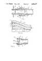
- FIG. 1is a detailed cross-sectional view of the completely assembled connector embodying the invention with the cross-section being taken along the axis of the connector;
- FIG. 1Ais an enlarged view of the tubing-connector juncture
- FIG. 2is a cross-sectional view of the collar which is part of the connector with the cross-section being taken along the axis of the collar;
- FIG. 3is a cross-sectional view of a connector of the present invention in combination with an artificial valve
- FIG. 3Ais an enlarged view of the valve-connector juncture
- FIG. 4is a cross-sectional view of the collar of the connector shown in FIG. 3;
- FIG. 5is a cross-sectional view of a connector of the present invention in combination with a blood-pump bladder
- FIG. 5Ais an enlarged view of the bladder-connector juncture
- FIG. 6is a cross-sectional view of the collar of the connector shown in FIG. 5.
- FIG. 1illustrates in a cross-sectional view a blood tubing connection which embodies the invention.
- the connectionwhich is used in an extra-corporeal, blood-handling system comprises a tubing coupler 1, a flexible tubing 2 and a collar 7.
- the tubing coupler 1is generally tubular in shape. It has a tubing section 1A with an outer end lC with a uniform inside diameter D1 and it has a coupling section 1B.
- the tubing coupler 1has a continuous inside surface 3 with a uniform inside diameter D1.
- the coupling section 1Bmates with another connector (not shown); thus its design depends upon the structure of the connector with which it mates.
- the tubing section 1Ahas an outer surface 4 over which the tubing 2 fits.
- the outer surface 4consists of a tapered portion 4A and ridges 4C and 4D that are contoured to form annular barbs.
- the tapered portion 4Ameets the inside surface 3 at a taper angle ⁇ to form a thin edge 5 at the outer end 1C of the tubing section 1A.
- the thickness of the edge 5is defined by a radius of curvature R (FIG. 1A).
- the tubing coupleris made from a material, such as polycarbonate, which is blood compatible and is also rigid so that the tubing coupler is not easily deformed during normal usage.
- the flexible tubing 2has a uniform outside diameter D2, a uniform inside diameter D3 which is equal to the inside diameter D1 of the tubing section 1A, and a wall 6.
- the tubing 2is typically made from a transparent polyvinyl chloride material which is flexible and which is sufficiently elastic to permit the tubing 2 to stretch slightly so that it can be forced over the outer surface 4 of the tubing coupler 1.
- a juncture 14is formed in the vicinity of edge 5 where the tubing 2 and the tubing section 1A meet.
- the collar 7, which is more clearly illustrated in the cross-sectional view of FIG. 2,is of unitary construction and has at least two sections: a taper section 9 and a tubular neck section 10 extending from the narrow end thereof.
- the section 9has a length approximately equal to the length of the tapered portion 4A of the tubing coupler 1 and has an inside surface 9A which has a taper angle ⁇ .
- the angle ⁇is preferably from zero degrees to 5 degrees greater than the angle ⁇ .
- the neck section 10has an inside diameter D4.
- the diameter D4is slightly smaller than the outside diameter D2 of the tubing 2 but still large enough to permit the tubing 2 to pass through it.
- D4can be selected to be approximately equal to 0.95 times the diameter D2.
- the componentsare assembled by first sliding the collar 7, neck section 10 first, over the tubing 2. Then the tubing 2 is forced onto the tubing section 1A of the tubing coupler 1 so that it conforms to the outer surface 4 of the tubing section 1A, as illustrated in FIG. 1. In this mounted configuration, the tubing 2 flares out over the tapered portion 4A and the ridges 4C and 4D tend to hold the tubing in place so that it does not slide off the tubing coupler 1. Next the collar 7 is pushed into an engaged position over the connection formed by the tubing 2 and the tubing coupler 1 so that the inner surface 9A compresses the tubing 2 against the tapered portion 4A of the tubing coupler 1. Since the inside diameter D4 of the neck section 10 is slightly smaller than the outside diameter D2 of the tubing 2, the neck section 10 compresses the tubing 2 which passes through the neck section 10.
- the compression of the tubing 2 between the inside surface 9A and the tapered portion 4Aforms a seal at the juncture 14 of the tubing 2 and the tubing coupler 1. Since the angle ⁇ is equal to or slightly larger than the angle of taper ⁇ and D2 is slightly smaller than D4, the compression of the tubing is greatest near the edge 5 of the tubing coupler 1. This causes the seal to focus around the edge 5. The compression thus urges the tubing 2 to conform with the surface of th tubing section 1A at and in the vicinity of edge 5, i.e. at the juncture 14 of the tubing 2 and the tubing coupler 1.
- tubing 2prevents the tubing 2 from separating from the tubing coupler 1 at the edge 5, thereby essentially eliminating any gaps, which might be caused by the tubing 2 not properly conforming to the tapered portion 4a, e.g. because of misalignment when the tubing and tubing coupler are joined together.
- the angle ⁇should lie in the range from about 15 degrees to 25 degrees. If the angle ⁇ is made much smaller than 15 degrees, the tapered portion 4A will be impractically long and the tubing coupler will become too thin and weak near the edge 5 of the tubing section 1A. On the other hand, if the angle ⁇ is made much larger than 25 degrees, forcing the tubing 2 onto the tubing coupler 1 will become difficult and the large angle will tend to deform the tubing 2 so that it does not naturally conform to the tapered portion 4A in the vicinity of edge 5.
- the neck section 10 on the collar 7serves a dual purpose. Since the neck section 10 compresses the tubing 2, it tends to reduce the size of the annular pocket 16 and thus the size of discontinuity in the juncture region 14 which disrupts the blood flow in that region. In addition, the neck section 10 isolates the juncture region 14 from strains caused by inadvertent or unavoidable flexing of the tubing 2. If the tubing 2 is permitted to flex in the vicinity of the juncture region 14, the tubing 1 may be pulled away from the tubing coupler 1 thus creating new discontinuities or gaps in the vicinity of the edge 5 which act as blood clot generation sites. The neck section 10 assures that this does not occur.
- the gripping section 8may take a number of different forms, one of which is shown in FIG. 2. As illustrated, it includes an annular recess 11. In addition, at equally spaced locations around the circumference of the section 8, there are slots 12A-D which extend the length of the gripping section 8. Circling the inside surface of the gripping section are grooves 15A-C. By binding the gripping section 8 with a tie rap (not shown) disposed within the annular recess 11, it may be compressed to grasp the tubing 2 and firmly anchor the collar 7 in place in the engaged position. The grooves 15A-C provide an articulated surface which further assists in anchoring the collar 7 so that it will not slide away from the engaged position.
- FIGS. 3 and 3Aillustrate another connection which embodies the invention. They show a cross-section of a connector which is used to connect a valve assembly into the blood flow path of an extra-corporeal blood handling system.
- the connectorcomprises a valve assembly 20, a coupler 22 and a collar 24. Blood which passes through the valve assembly 20 is transmitted to other components in the extracorporeal blood handling system through the coupler 22.
- the valve assembly 20similar to an artificial heart valve, includes a plurality of valve leaflets 26 supported inside a conduit 28 which has a wall 30.
- the conduit 28is made of a flexible, polymeric material that is compatible with blood such as a polyurethane elastomer.
- Coupler 22to which the valve assembly 20 is coupled, is generally tubular in shape and is made of a rigid, blood compatible material such as polycarbonate.
- the coupler 22has an inside surface 34 defining a bore 36 which extends through the coupler and provides a passage through which blood can flow.
- a coupling section 22Bwhich mates with another component in the blood handling system such as a blood pump (not shown in the illustrations).
- a connecting section 22Ato which the valve assembly 20 attaches.
- the connecting section 22Ahas an outer surface 32 which has a tapered portion 32A that meets the inside surface 34 to form a thin rounded edge 38 at the distal end 22C of conduit 22.
- Tapered portion 32Atapers inward at taper angle ⁇ from the axis of bore 36, corresponding to the same taper angle in the previous embodiment.
- the rounded edge 38has a radius of curvature R2.
- the bore 36has a diameter D5.
- the collar 24is ring shaped and has an inner surface 40 with a tapered portion 40A, which tapers outward at taper angle ⁇ from the bore of the collar, corresponding to the same taper angle in the previous embodiment.
- taper angle ⁇is preferably from 5 to 10 degrees greater than taper angle ⁇ .
- the inner tapered portion 40A of the collar 24has a length approximately equal to the length of the outer tapered portion 32A of the coupler 22.
- the tapered portion 40Arestricts down to an inside diameter of D6 which is no larger than the sum of the diameter D5 of the bore 36 at the outer end 22C plus twice the thickness of the wall 30.
- the diameter D6, however,is not so small as to distort the generally circular shape of the conduit 28 when it is passed through the collar 24 as described hereinafter.
- Collar 24also includes a tubular neck section 41 which has an inner diameter through its length equal to or less than the diameter D6 at the narrowest point of tapered portion 40A.
- Neck section 41limits the flexing of conduit 28 in the vicinity of the juncture region 44, and thereby minimizes disturbances in the flow of blood through this region.
- Conduit 28is inserted through collar 24 so that it is encircled by the collar. Then, conduit 28 is fitted over connecting section 22A of coupler 22 so that it closely conforms to the tapered portion 32A of the outer surface 32 and forms a juncture 44 in the vicinity of edge 38 where conduit 28 meets coupler 22. Next, collar 24 is pushed down over the connection formed by conduit 28 and coupler 22 so that the inner surface 40A compresses the wall 30 against the tapered portion 32A.
- taper angle ⁇should preferably fall within the range of 15 to 25 degrees. Due to the relative size of the two taper angles ⁇ and ⁇ , coupled with the size limitation on the diameter D6, collar 24 focuses the compression of conduit 28 near the outer end 22C of coupler 22. Thus, as with the blood tubing connection described above, the compression of the conduit 28 between the inner tapered portion 40A of the collar 24 and the outer tapered portion 32A of the coupler 22 forms a seal at the juncture 44 in the vicinity of the edge 38.
- the sealprevents the conduit 28 from separating from the connecting section 22A, thereby preventing gaps from forming in the vicinity of the edge 38 which would create generation sites for blood clots.
- the compression of the conduit 28 in the vicinity of the juncture 44encourages conduit 28 to conform to the tapered portion 32A around the edge 38 thereby reducing any discontinuity that exists at the juncture 44. If the radius of curvature R2 of the edge 38 is greater than about 0.005 inches but less than about 0.010 inches, the edge 38 will be durable enough to resist deforming under use and, at the same time, small enough to not provoke serious blood clotting problems in the vicinity of the edge 38 when the collar 24 is in place.
- One such methodis illustrated in FIG. 3.
- a retaining ring 46is threaded onto the valve coupler 22 and holds the collar 24 in place.
- FIGS. 5 and 5Ashow a cross-section of a bladder connection used on a blood pump.
- the bladder connectioncomprises a bladder 50, a bladder coupler 52 and a bladder collar 54.
- the bladder 50is generally tubular in shape with an opening at either end. It has a wall 60 and is made of a flexible, polymeric blood-compatible material such as a polyurethane elastomer.
- the inside of bladder 50forms a chamber 50A through which blood passes.
- By periodically compressing and expanding bladder 50blood is forced out of and drawn into bladder chamber 50A.
- a one-way valvesuch as the valve 20 illustrated in FIG. 3, the periodic compressions and expansions of the bladder propel the blood in one direction through the blood handling system to which it is attached.
- the means for compressing and expanding bladder 50are not illustrated in the figures but such means are well known to persons skilled in the art.
- the bladder coupler 52is generally tubular in shape and is made of a rigid, blood-compatible material such as polycarbonate.
- the coupler 52has an inside surface 64 defining a bore 66 which extends through coupler 52 and provides a passage through which blood can flow.
- a coupling section 52Bwhich mates with another component in the blood handling system such as a blood tubing.
- a connecting section 52Awhich connects to the bladder 50.
- the connecting section 52Ahas an outer surface 62 which has a tapered portion 62A that meets the inside surface 64 to form a thin rounded edge 68 at the distal end 52C of the coupler.
- Tapered portion 62Atapers inward at taper angle ⁇ from the axis of bore 66, as with the correspondingly identified coupler taper angles in the previous embodiments. Also as in the previous embodiments, taper angle ⁇ is
- the rounded edge 68has a radius of curvature R3.
- the bore 66has a diameter D7.
- the bladder collar 54which is more clearly illustrated in the cross-sectional view of FIG. 6, is ring shaped and has an inner surface 70 with a taper portion 70A
- the angle ⁇is preferably from 5 to 10 degrees greater than the angle ⁇ .
- the tapered portion 70Arestricts down to an inside diameter D8 which is no larger than the sum of the diameter D7 of bore 66 at outer end 52C plus twice the thickness of bladder wall 60.
- the diameter D8is not so small as to adversely distort bladder 50 when it is inserted through the collar 54 as described hereinafter.
- Bladder collar 54also includes a tubular neck section 71 which has an inner diameter through its length equal to or less than the diameter D8 at the narrowest point of tapered portion 70A. As described in relation to the previous embodiment, neck section 71 limits the flexing of bladder 50 in the vicinity of the juncture region 74, and thereby minimizes disturbances in the flow of blood through this region.
- the bladder collar 54functions in substantially the same manner as the collars 7 and 24 described in the other embodiments above.
- the assembly of the bladder connectionis slightly different from the previously described procedures since the bladder 50 is typically supported in a blood pump housing prior to connection to other components in the blood handling system.
- collar 54is incorporated into the blood pump housing and provides the means for supporting bladder 50 so that it can be connected to coupler 52 when the pump is put in the blood handling system.
- the end of bladder 50 which is to be connected to coupler 52is inserted through bladder collar 54 in the direction of restriction so that bladder 50 extends out the other side of collar 54.
- the end of bladder 50is then folded back over collar 54 so that it encircles the outside circumference of the end of collar 54.
- wall 60 of bladder 50conforms to the inner surface 70A of the tapered section 70 and collar 54 supports bladder 50.
- bladder coupler 52is inserted into bladder collar 54 so that the tapered portion 62A of the coupler outer surface 62 compresses the bladder wall 60 against the inner tapered portion 70A of the collar.
- a juncture 74is formed in the vicinity of the thin rounded edge 68 where bladder 50 meets coupler 52.
- the compression of the bladder wall 60 between the inner tapered portion 70A and the outer tapered portion 62Aforms a seal in the vicinity of the edge 68.
- the radius of curvature R3be greater than about 0.005 inches but less than about 0.010 inches to achieve acceptable durability and at the same time maintain the discontinuities in the assembled connection within acceptable limits. If R is kept substantially around this range, the discontinuity between the bladder wall 60 and the inside surface 64 of the coupler 52 in the assembled connection will not constitute a serious blood clot generation site.
- the collar 54is held in place by a retaining ring 76 which is threaded onto collar 54 and urges coupler 52 into collar 54.
- the retaining ring 76assists in maintaining a constant compression of the bladder in the vicinity of juncture 74 and prevents collar 54 from being dislodged from coupler 52.
- the retaining ring 76is merely illustrative of one of many alternatives methods of holding the collar 54 in place.
- connections described herein, which embody the invention,do not exhibit the serious blood clotting problems which are typically associated with connections found in the prior art.
- the inventionsubstantially reduces the occurrence and magnitude of discontinuities at the point where the flexible component meets the coupler so that the connection does not provide a generation site for blood clots.
Landscapes
- Health & Medical Sciences (AREA)
- Heart & Thoracic Surgery (AREA)
- Pulmonology (AREA)
- Engineering & Computer Science (AREA)
- Anesthesiology (AREA)
- Biomedical Technology (AREA)
- Hematology (AREA)
- Life Sciences & Earth Sciences (AREA)
- Animal Behavior & Ethology (AREA)
- General Health & Medical Sciences (AREA)
- Public Health (AREA)
- Veterinary Medicine (AREA)
- External Artificial Organs (AREA)
Abstract
Description
Claims (7)
Priority Applications (5)
| Application Number | Priority Date | Filing Date | Title |
|---|---|---|---|
| US07/093,592US4826477A (en) | 1986-09-19 | 1987-09-10 | Connector for blood handling systems |
| PCT/US1987/002354WO1988001887A1 (en) | 1986-09-19 | 1987-09-16 | Connector for blood handling systems |
| AU80248/87AAU8024887A (en) | 1986-09-19 | 1987-09-16 | Connector for blood handling systems |
| EP19870906526EP0292510A4 (en) | 1986-09-19 | 1987-09-16 | Connector for blood handling systems. |
| IL83951AIL83951A0 (en) | 1986-09-19 | 1987-09-18 | Connector for blood handling systems |
Applications Claiming Priority (2)
| Application Number | Priority Date | Filing Date | Title |
|---|---|---|---|
| US90982886A | 1986-09-19 | 1986-09-19 | |
| US07/093,592US4826477A (en) | 1986-09-19 | 1987-09-10 | Connector for blood handling systems |
Related Parent Applications (1)
| Application Number | Title | Priority Date | Filing Date |
|---|---|---|---|
| US90982886AContinuation-In-Part | 1986-09-19 | 1986-09-19 |
Publications (1)
| Publication Number | Publication Date |
|---|---|
| US4826477Atrue US4826477A (en) | 1989-05-02 |
Family
ID=26787713
Family Applications (1)
| Application Number | Title | Priority Date | Filing Date |
|---|---|---|---|
| US07/093,592Expired - LifetimeUS4826477A (en) | 1986-09-19 | 1987-09-10 | Connector for blood handling systems |
Country Status (5)
| Country | Link |
|---|---|
| US (1) | US4826477A (en) |
| EP (1) | EP0292510A4 (en) |
| AU (1) | AU8024887A (en) |
| IL (1) | IL83951A0 (en) |
| WO (1) | WO1988001887A1 (en) |
Cited By (43)
| Publication number | Priority date | Publication date | Assignee | Title |
|---|---|---|---|---|
| US5279597A (en)* | 1992-01-13 | 1994-01-18 | Arrow International Investment Corp. | Catheter compression clamp |
| US5304164A (en)* | 1990-03-14 | 1994-04-19 | Minnesota Mining And Manufacturing Company | Quick-changeover blood handling apparatus |
| US5344385A (en)* | 1991-09-30 | 1994-09-06 | Thoratec Laboratories Corporation | Step-down skeletal muscle energy conversion system |
| US5399168A (en)* | 1991-08-29 | 1995-03-21 | C. R. Bard, Inc. | Implantable plural fluid cavity port |
| US5637102A (en)* | 1995-05-24 | 1997-06-10 | C. R. Bard, Inc. | Dual-type catheter connection system |
| US5685858A (en)* | 1995-05-17 | 1997-11-11 | Datascope Corp. | Slidable seal for use with a catheter gard unit |
| US5792104A (en)* | 1996-12-10 | 1998-08-11 | Medtronic, Inc. | Dual-reservoir vascular access port |
| US5882047A (en)* | 1996-12-20 | 1999-03-16 | Itt Automotive, Inc. | Quick connector fluid coupling |
| GB2332932A (en)* | 1998-01-06 | 1999-07-07 | Smiths Industries Plc | Connector for insertion into reinforced tube |
| US5944697A (en)* | 1994-05-31 | 1999-08-31 | Universal Medical Instrument Corp. | Percutaneous catheter introducer |
| US5954702A (en)* | 1996-05-03 | 1999-09-21 | Baxter International Inc. | Interface geometry for adhesive bonds |
| US5958338A (en)* | 1997-10-31 | 1999-09-28 | Terumo Cardiovascular Systems Corporation | Mounting apparatus for blood handling systems |
| US5984378A (en)* | 1996-12-20 | 1999-11-16 | Itt Automotive, Inc. | Inline quick connector |
| US6113572A (en)* | 1995-05-24 | 2000-09-05 | C. R. Bard, Inc. | Multiple-type catheter connection systems |
| US6155302A (en)* | 1996-01-27 | 2000-12-05 | Robert Bosch Gmbh | Fastening device for attaching a fuel line to a connecting piece |
| US6165149A (en)* | 1995-07-20 | 2000-12-26 | Dsu Medical Corporation | Reusable blood lines |
| US6319231B1 (en) | 1999-02-12 | 2001-11-20 | Abiomed, Inc. | Medical connector |
| US20020022801A1 (en)* | 2000-08-15 | 2002-02-21 | Delegge Rebecca | Gastric access port |
| US20030120260A1 (en)* | 2001-12-26 | 2003-06-26 | Chu Michael S. H. | Low profile adaptor for use with a medical catheter |
| US20030158539A1 (en)* | 2002-02-19 | 2003-08-21 | Laddvanh Bouphavichith | Low profile adaptor for use with a medical catheter |
| US20030163119A1 (en)* | 2002-02-26 | 2003-08-28 | Chu Michael S.H | Medical catheter assembly including a removable inner sleeve and method of using the same |
| US20030212385A1 (en)* | 2002-05-09 | 2003-11-13 | Brenner Laurence D. | Low profile adaptor for use with a medical catheter |
| WO2004003418A1 (en)* | 2002-06-28 | 2004-01-08 | Societe Des Produits Nestle S.A | Hose fitment for disposable food container |
| US20040045447A1 (en)* | 2002-09-09 | 2004-03-11 | Ramon Navarro | Sanitary hose couplers |
| US20050054968A1 (en)* | 2003-09-05 | 2005-03-10 | Gambro Dasco S.P.A. | Blood chamber for extracorporeal blood circuits and a process for manufacturing the blood chamber |
| US20050192559A1 (en)* | 2004-03-01 | 2005-09-01 | Michels Lester D. | Delivery system and method |
| US6971390B1 (en) | 2002-02-05 | 2005-12-06 | C. R. Bard, Inc. | Catheter connection and repair system |
| US7083595B2 (en) | 2002-05-01 | 2006-08-01 | Scimed Lipe Systems, Inc. | Medical catheter assembly and method of using the same |
| EP1743583A1 (en)* | 2005-07-14 | 2007-01-17 | BIOENGINEERING LABORATORIES S.p.A. | Surgical instrument for making backward subcutaneous tunnelling |
| US20070208290A1 (en)* | 2006-03-06 | 2007-09-06 | Robert Pecor | Quick priming connectors for blood circuit |
| US20080284163A1 (en)* | 2007-05-15 | 2008-11-20 | Millipore Corporation | Connector for flexible tubing |
| US20090182272A1 (en)* | 2002-02-19 | 2009-07-16 | Changqing Li | Medical catheter assembly including multi-piece connector |
| US20090220294A1 (en)* | 2007-05-15 | 2009-09-03 | Millipore Corporation | Connector for flexible tubing |
| US20100030194A1 (en)* | 2006-11-06 | 2010-02-04 | Terumo Kabushiki Kaisha | Connector and infusion tube set |
| US20100272148A1 (en)* | 2009-04-23 | 2010-10-28 | Medtronic, Inc. | Multiple Use Temperature Monitor Adapter, System and Method of Using Same |
| WO2011153302A3 (en)* | 2010-06-02 | 2012-05-18 | Zarate Alfredo R | Hemodialysis system and method |
| US20150038920A1 (en)* | 2011-08-23 | 2015-02-05 | Aspire Bariatric, Inc. | Skin port connector and method of installation |
| US20160175577A1 (en)* | 2014-12-22 | 2016-06-23 | Anthony Solazzo | Ureteral Catheter Connector Adapter |
| US20180224035A1 (en)* | 2015-08-18 | 2018-08-09 | Christoph Steinkamp | Connecting Arrangement and Press Ring for A Connecting Arrangement |
| US10322275B2 (en) | 2015-10-30 | 2019-06-18 | ECMOtek, LLC | Devices for endovascular access through extracorporeal life support circuits |
| US11391398B2 (en)* | 2019-02-27 | 2022-07-19 | Delphi Technologies Ip Limited | Fuel system including reinforced fuel connector with retaining rings |
| US20230001176A1 (en)* | 2019-12-10 | 2023-01-05 | B. Braun Melsungen Ag | Connector, system with connector and hose line, and method for connecting a connector to a hose line |
| USRE50347E1 (en) | 2015-10-30 | 2025-03-25 | ECMOtek, LLC | Devices for endovascular access through extracorporeal life support circuits |
Families Citing this family (16)
| Publication number | Priority date | Publication date | Assignee | Title |
|---|---|---|---|---|
| WO1991019522A1 (en)* | 1990-06-14 | 1991-12-26 | Baxter International Inc. | Needle assembly for reduced coagulation |
| GB9117958D0 (en)* | 1991-08-20 | 1991-10-09 | United Kingdom Aromic Energy A | A joint |
| FR2750055B1 (en)* | 1996-06-20 | 1998-08-07 | Braun Celsa Sa | MEDICAL ASSEMBLY OF REMOVABLE LINK BETWEEN A TUBE AND A ROD |
| US20050228364A1 (en)* | 2004-04-09 | 2005-10-13 | Richard Braga | Tunneler device |
| NL1036815C2 (en)* | 2009-04-03 | 2010-10-05 | Weir Minerals Netherlands Bv | Coupling system for a hose structure, in particular for use in a pump system for displacing a medium as well as such a pump system. |
| CA3066361A1 (en) | 2017-06-07 | 2018-12-13 | Shifamed Holdings, Llc | Intravascular fluid movement devices, systems, and methods of use |
| WO2019094963A1 (en) | 2017-11-13 | 2019-05-16 | Shifamed Holdings, Llc | Intravascular fluid movement devices, systems, and methods of use |
| CN112004563B (en) | 2018-02-01 | 2024-08-06 | 施菲姆德控股有限责任公司 | Intravascular blood pump and methods of use and manufacture |
| US12161857B2 (en) | 2018-07-31 | 2024-12-10 | Shifamed Holdings, Llc | Intravascular blood pumps and methods of use |
| WO2020073047A1 (en) | 2018-10-05 | 2020-04-09 | Shifamed Holdings, Llc | Intravascular blood pumps and methods of use |
| WO2021011473A1 (en) | 2019-07-12 | 2021-01-21 | Shifamed Holdings, Llc | Intravascular blood pumps and methods of manufacture and use |
| US11654275B2 (en) | 2019-07-22 | 2023-05-23 | Shifamed Holdings, Llc | Intravascular blood pumps with struts and methods of use and manufacture |
| WO2021062265A1 (en) | 2019-09-25 | 2021-04-01 | Shifamed Holdings, Llc | Intravascular blood pump systems and methods of use and control thereof |
| US12121713B2 (en) | 2019-09-25 | 2024-10-22 | Shifamed Holdings, Llc | Catheter blood pumps and collapsible blood conduits |
| EP4501393A3 (en) | 2019-09-25 | 2025-04-09 | Shifamed Holdings, LLC | Catheter blood pumps and collapsible pump housings |
| EP4072650A4 (en) | 2019-12-11 | 2024-01-10 | Shifamed Holdings, LLC | Descending aorta and vena cava blood pumps |
Citations (2)
| Publication number | Priority date | Publication date | Assignee | Title |
|---|---|---|---|---|
| US4049034A (en)* | 1976-07-14 | 1977-09-20 | Baxter Travenol Laboratories, Inc. | Attaching means and method for attaching flexible tubing to a plastic container |
| US4588402A (en)* | 1982-03-09 | 1986-05-13 | Terumo Kabushiki Kaisha | Connector for medical tubing and medical solution bag device using the connector |
Family Cites Families (7)
| Publication number | Priority date | Publication date | Assignee | Title |
|---|---|---|---|---|
| NL97556C (en)* | 1953-04-08 | |||
| US4194509A (en)* | 1978-04-11 | 1980-03-25 | C. R. Bard, Inc. | Preconnected catheter drainage system |
| NL185061C (en)* | 1978-07-03 | 1990-01-16 | Smiths Industries Plc | CONNECTING DEVICE. |
| US4437689A (en)* | 1981-04-03 | 1984-03-20 | Titeflex Corporation | Reusable end fitting |
| DE3122709C2 (en)* | 1981-06-06 | 1986-03-20 | Rasmussen Gmbh, 6457 Maintal | Hose coupling and method for attaching a hose to a connection piece of this coupling |
| US4511163A (en)* | 1982-07-14 | 1985-04-16 | Mead Johnson & Company | Adaptable tip tubing connector |
| DD227049A1 (en)* | 1984-10-09 | 1985-09-11 | Medizin Labortechnik Veb K | DEVICE FOR PRODUCING A HOSE CONNECTION |
- 1987
- 1987-09-10USUS07/093,592patent/US4826477A/ennot_activeExpired - Lifetime
- 1987-09-16AUAU80248/87Apatent/AU8024887A/ennot_activeAbandoned
- 1987-09-16EPEP19870906526patent/EP0292510A4/ennot_activeWithdrawn
- 1987-09-16WOPCT/US1987/002354patent/WO1988001887A1/ennot_activeApplication Discontinuation
- 1987-09-18ILIL83951Apatent/IL83951A0/enunknown
Patent Citations (2)
| Publication number | Priority date | Publication date | Assignee | Title |
|---|---|---|---|---|
| US4049034A (en)* | 1976-07-14 | 1977-09-20 | Baxter Travenol Laboratories, Inc. | Attaching means and method for attaching flexible tubing to a plastic container |
| US4588402A (en)* | 1982-03-09 | 1986-05-13 | Terumo Kabushiki Kaisha | Connector for medical tubing and medical solution bag device using the connector |
Cited By (86)
| Publication number | Priority date | Publication date | Assignee | Title |
|---|---|---|---|---|
| US5304164A (en)* | 1990-03-14 | 1994-04-19 | Minnesota Mining And Manufacturing Company | Quick-changeover blood handling apparatus |
| US5399168A (en)* | 1991-08-29 | 1995-03-21 | C. R. Bard, Inc. | Implantable plural fluid cavity port |
| US5653676A (en)* | 1991-09-30 | 1997-08-05 | Thoratec Laboratories Corporation | Step-down skeletal muscle energy conversion method |
| US5344385A (en)* | 1991-09-30 | 1994-09-06 | Thoratec Laboratories Corporation | Step-down skeletal muscle energy conversion system |
| US5984857A (en)* | 1991-09-30 | 1999-11-16 | Thoratec Laboratories Corporation | Step-down skeletal muscle energy conversion system |
| US5701919A (en)* | 1991-09-30 | 1997-12-30 | Thoratec Laboratories Corporation | Step-down skeletal muscle energy conversion system |
| US5505714A (en)* | 1992-01-13 | 1996-04-09 | Arrow International Investment Corp. | Non-rotational catheter compression clamp |
| US5279597A (en)* | 1992-01-13 | 1994-01-18 | Arrow International Investment Corp. | Catheter compression clamp |
| US5944697A (en)* | 1994-05-31 | 1999-08-31 | Universal Medical Instrument Corp. | Percutaneous catheter introducer |
| US5685858A (en)* | 1995-05-17 | 1997-11-11 | Datascope Corp. | Slidable seal for use with a catheter gard unit |
| US5637102A (en)* | 1995-05-24 | 1997-06-10 | C. R. Bard, Inc. | Dual-type catheter connection system |
| US6113572A (en)* | 1995-05-24 | 2000-09-05 | C. R. Bard, Inc. | Multiple-type catheter connection systems |
| US6620119B1 (en) | 1995-07-20 | 2003-09-16 | Dsu Medical Corporation | Reusable blood lines |
| US6666839B2 (en) | 1995-07-20 | 2003-12-23 | Dsu Medical Corporation | Method of using reusable blood lines |
| US6165149A (en)* | 1995-07-20 | 2000-12-26 | Dsu Medical Corporation | Reusable blood lines |
| US6155302A (en)* | 1996-01-27 | 2000-12-05 | Robert Bosch Gmbh | Fastening device for attaching a fuel line to a connecting piece |
| US5954702A (en)* | 1996-05-03 | 1999-09-21 | Baxter International Inc. | Interface geometry for adhesive bonds |
| US5792104A (en)* | 1996-12-10 | 1998-08-11 | Medtronic, Inc. | Dual-reservoir vascular access port |
| US5882047A (en)* | 1996-12-20 | 1999-03-16 | Itt Automotive, Inc. | Quick connector fluid coupling |
| US5984378A (en)* | 1996-12-20 | 1999-11-16 | Itt Automotive, Inc. | Inline quick connector |
| US5958338A (en)* | 1997-10-31 | 1999-09-28 | Terumo Cardiovascular Systems Corporation | Mounting apparatus for blood handling systems |
| GB2332932B (en)* | 1998-01-06 | 2002-07-03 | Smiths Industries Plc | Connectors and assemblies |
| GB2332932A (en)* | 1998-01-06 | 1999-07-07 | Smiths Industries Plc | Connector for insertion into reinforced tube |
| US6319231B1 (en) | 1999-02-12 | 2001-11-20 | Abiomed, Inc. | Medical connector |
| US8043260B2 (en)* | 2000-08-15 | 2011-10-25 | Delegge Medical, Inc. | Gastric access port |
| US6872189B2 (en) | 2000-08-15 | 2005-03-29 | Hammerhead Design And Development, Inc. | Gastric access port |
| US20020022801A1 (en)* | 2000-08-15 | 2002-02-21 | Delegge Rebecca | Gastric access port |
| WO2002013901A3 (en)* | 2000-08-15 | 2003-09-25 | Rebecca Delegge | Gastric access port |
| JP4759215B2 (en)* | 2000-08-15 | 2011-08-31 | ハマヘッド デザイン アンド ディベラップメント、インコーポレイテッド | Stomach access port |
| US20090082736A1 (en)* | 2000-08-15 | 2009-03-26 | Delegge Rebecca | Gastric access port |
| US20030120260A1 (en)* | 2001-12-26 | 2003-06-26 | Chu Michael S. H. | Low profile adaptor for use with a medical catheter |
| US6979322B2 (en) | 2001-12-26 | 2005-12-27 | Scimed Life Systems, Inc. | Low profile adaptor for use with a medical catheter |
| US20060127165A1 (en)* | 2002-02-05 | 2006-06-15 | C. R. Bard, Inc. | Connection methods |
| US6971390B1 (en) | 2002-02-05 | 2005-12-06 | C. R. Bard, Inc. | Catheter connection and repair system |
| US8226632B2 (en) | 2002-02-05 | 2012-07-24 | C. R. Bard, Inc. | Connection methods |
| US8187253B2 (en) | 2002-02-19 | 2012-05-29 | Boston Scientific Scimed, Inc. | Low profile adaptor for use with a medical catheter |
| US20050010195A1 (en)* | 2002-02-19 | 2005-01-13 | Laddvanh Bouphavichith | Low profile adaptor for use with a medical catheter |
| US6802836B2 (en)* | 2002-02-19 | 2004-10-12 | Scimed Life Systems, Inc. | Low profile adaptor for use with a medical catheter |
| US8308713B2 (en) | 2002-02-19 | 2012-11-13 | Boston Scientific Scimed, Inc. | Medical catheter assembly including multi-piece connector |
| US20100076383A1 (en)* | 2002-02-19 | 2010-03-25 | Boston Scientific Scimed, Inc. | Low profile adaptor for use with a medical catheter |
| US20030158539A1 (en)* | 2002-02-19 | 2003-08-21 | Laddvanh Bouphavichith | Low profile adaptor for use with a medical catheter |
| US7641648B2 (en) | 2002-02-19 | 2010-01-05 | Boston Scientific Scimed, Inc. | Low profile adaptor for use with a medical catheter |
| US20090182272A1 (en)* | 2002-02-19 | 2009-07-16 | Changqing Li | Medical catheter assembly including multi-piece connector |
| US8241252B2 (en) | 2002-02-26 | 2012-08-14 | Boston Scientific Scimed, Inc. | Medical catheter assembly including a removable inner sleeve and method of using the same |
| US7041083B2 (en) | 2002-02-26 | 2006-05-09 | Scimed Life Systems, Inc. | Medical catheter assembly including a removable inner sleeve and method of using the same |
| US20030163119A1 (en)* | 2002-02-26 | 2003-08-28 | Chu Michael S.H | Medical catheter assembly including a removable inner sleeve and method of using the same |
| US20060206095A1 (en)* | 2002-02-26 | 2006-09-14 | Chu Michael S | Medical catheter assembly including a removable inner sleeve and method of using the same |
| US7083595B2 (en) | 2002-05-01 | 2006-08-01 | Scimed Lipe Systems, Inc. | Medical catheter assembly and method of using the same |
| US8029462B2 (en) | 2002-05-01 | 2011-10-04 | Boston Scientific Scimed, Inc. | Medical catheter assembly and method of using the same |
| US20060100604A1 (en)* | 2002-05-09 | 2006-05-11 | Brenner Laurence D | Low profile adaptor for use with a medical catheter |
| US20030212385A1 (en)* | 2002-05-09 | 2003-11-13 | Brenner Laurence D. | Low profile adaptor for use with a medical catheter |
| US8221389B2 (en) | 2002-05-09 | 2012-07-17 | Boston Scientific Scimed, Inc. | Low profile adaptor for use with a medical catheter |
| US6976980B2 (en) | 2002-05-09 | 2005-12-20 | Scimed Life Systems, Inc. | Low profile adaptor for use with a medical catheter |
| WO2004003418A1 (en)* | 2002-06-28 | 2004-01-08 | Societe Des Produits Nestle S.A | Hose fitment for disposable food container |
| US7185921B2 (en) | 2002-06-28 | 2007-03-06 | Nestec S.A. | Hose fitment for disposable food container |
| RU2307281C2 (en)* | 2002-06-28 | 2007-09-27 | Сосьете Де Продюи Нестле С.А. | Hose assembly for disposable food package |
| US20040045447A1 (en)* | 2002-09-09 | 2004-03-11 | Ramon Navarro | Sanitary hose couplers |
| US20050054968A1 (en)* | 2003-09-05 | 2005-03-10 | Gambro Dasco S.P.A. | Blood chamber for extracorporeal blood circuits and a process for manufacturing the blood chamber |
| US7559911B2 (en)* | 2003-09-05 | 2009-07-14 | Gambro Lundia Ab | Blood chamber for extracorporeal blood circuits and a process for manufacturing the blood chamber |
| US20050192559A1 (en)* | 2004-03-01 | 2005-09-01 | Michels Lester D. | Delivery system and method |
| US8608728B2 (en) | 2004-03-01 | 2013-12-17 | Smiths Medical Asd, Inc. | Delivery system and method |
| US8608727B2 (en) | 2004-03-01 | 2013-12-17 | Smiths Medical Asd, Inc. | Delivery system and method |
| EP1743583A1 (en)* | 2005-07-14 | 2007-01-17 | BIOENGINEERING LABORATORIES S.p.A. | Surgical instrument for making backward subcutaneous tunnelling |
| US20070208290A1 (en)* | 2006-03-06 | 2007-09-06 | Robert Pecor | Quick priming connectors for blood circuit |
| US8157758B2 (en) | 2006-03-06 | 2012-04-17 | Thoratec Corporation | Quick priming connectors for blood circuit |
| US7438699B2 (en) | 2006-03-06 | 2008-10-21 | Orqis Medical Corporation | Quick priming connectors for blood circuit |
| US20100030194A1 (en)* | 2006-11-06 | 2010-02-04 | Terumo Kabushiki Kaisha | Connector and infusion tube set |
| US8182468B2 (en)* | 2006-11-06 | 2012-05-22 | Terumo Kabushiki Kaisha | Connector and infusion tube set |
| US8297661B2 (en)* | 2007-05-15 | 2012-10-30 | Emd Millipore Corporation | Connector for flexible tubing |
| US20080284163A1 (en)* | 2007-05-15 | 2008-11-20 | Millipore Corporation | Connector for flexible tubing |
| US20090220294A1 (en)* | 2007-05-15 | 2009-09-03 | Millipore Corporation | Connector for flexible tubing |
| US8926175B2 (en) | 2009-04-23 | 2015-01-06 | Medtronic, Inc. | Multiple use temperature monitor adapter, system and method of using same |
| US20100272148A1 (en)* | 2009-04-23 | 2010-10-28 | Medtronic, Inc. | Multiple Use Temperature Monitor Adapter, System and Method of Using Same |
| US8057095B2 (en) | 2009-04-23 | 2011-11-15 | Medtronic, Inc. | Multiple use temperature monitor adapter, system and method of using same |
| CN103068417A (en)* | 2010-06-02 | 2013-04-24 | 阿尔佛雷德·R·扎拉特 | Hemodialysis system and method |
| WO2011153302A3 (en)* | 2010-06-02 | 2012-05-18 | Zarate Alfredo R | Hemodialysis system and method |
| US20150038920A1 (en)* | 2011-08-23 | 2015-02-05 | Aspire Bariatric, Inc. | Skin port connector and method of installation |
| US9789030B2 (en)* | 2011-08-23 | 2017-10-17 | Aspire Bariatrics, Inc. | Skin port connector and method of installation |
| US20160175577A1 (en)* | 2014-12-22 | 2016-06-23 | Anthony Solazzo | Ureteral Catheter Connector Adapter |
| US20180224035A1 (en)* | 2015-08-18 | 2018-08-09 | Christoph Steinkamp | Connecting Arrangement and Press Ring for A Connecting Arrangement |
| US10322275B2 (en) | 2015-10-30 | 2019-06-18 | ECMOtek, LLC | Devices for endovascular access through extracorporeal life support circuits |
| US10441774B2 (en) | 2015-10-30 | 2019-10-15 | ECMOtek, LLC | Devices for endovascular access through extracorporeal life support circuits |
| US10576260B2 (en) | 2015-10-30 | 2020-03-03 | ECMOtek, LLC | Devices for endovascular access through extracorporeal life support circuits |
| USRE50347E1 (en) | 2015-10-30 | 2025-03-25 | ECMOtek, LLC | Devices for endovascular access through extracorporeal life support circuits |
| US11391398B2 (en)* | 2019-02-27 | 2022-07-19 | Delphi Technologies Ip Limited | Fuel system including reinforced fuel connector with retaining rings |
| US20230001176A1 (en)* | 2019-12-10 | 2023-01-05 | B. Braun Melsungen Ag | Connector, system with connector and hose line, and method for connecting a connector to a hose line |
Also Published As
| Publication number | Publication date |
|---|---|
| EP0292510A1 (en) | 1988-11-30 |
| WO1988001887A1 (en) | 1988-03-24 |
| IL83951A0 (en) | 1988-02-29 |
| AU8024887A (en) | 1988-04-07 |
| EP0292510A4 (en) | 1989-08-09 |
Similar Documents
| Publication | Publication Date | Title |
|---|---|---|
| US4826477A (en) | Connector for blood handling systems | |
| EP1789129B1 (en) | Heart pump connector | |
| US4086665A (en) | Artificial blood conduit | |
| EP4251257B1 (en) | Para-aortic blood pump device | |
| US4118806A (en) | Prosthetic blood vessel | |
| US6752827B2 (en) | Devices, systems, and methods for subcutaneously placing an article | |
| WO2000028924A2 (en) | Smooth ventricular assist device conduit | |
| EP1208867A3 (en) | Endovascular system for arresting the heart | |
| US20140018772A1 (en) | Self-centering catheter with anti-occlusion features | |
| EP1107811A1 (en) | Rigid clampable cannula | |
| GB2105197A (en) | Body implantable connector for connection to an implant device | |
| US11801379B2 (en) | Aortic connectors and methods of use | |
| US12017059B2 (en) | Implantable heart pump systems including an improved apical connector and/or graft connector | |
| CN115708925A (en) | Blood pumping catheter and blood pump device | |
| US12257427B2 (en) | Implantable heart pump systems including an improved apical connector and/or graft connector | |
| JPH03126463A (en) | Connector for artificial heart | |
| JPH0411716Y2 (en) | ||
| JPH02206468A (en) | Connector of tube body | |
| CN116997383A (en) | Aortic bypass blood pump device | |
| CN117083100A (en) | Ventricular assist device with built-in pressure sensor | |
| JPS59203568A (en) | canyule | |
| JPS63135693A (en) | Fluid conduit with built-in valve | |
| AU2004222674A1 (en) | Improved cannula |
Legal Events
| Date | Code | Title | Description |
|---|---|---|---|
| AS | Assignment | Owner name:ABIOMED CARDIOVASCULAR, INC., 33 CHERRY HILL DRIVE Free format text:ASSIGNMENT OF ASSIGNORS INTEREST.;ASSIGNOR:ADAMS, BRUCE B.;REEL/FRAME:004812/0115 Effective date:19871027 | |
| STCF | Information on status: patent grant | Free format text:PATENTED CASE | |
| AS | Assignment | Owner name:ABIOMED LIMITED PARTNERSHIP, MASSACHUSETTS Free format text:ASSIGNMENT OF ASSIGNORS INTEREST.;ASSIGNOR:ABIOMED CARDIOVASCULAR, INC.;REEL/FRAME:005115/0322 Effective date:19890612 | |
| AS | Assignment | Owner name:ABIOMED, INC., 33 CHERRY HILL DRIVE, DANVERS, MA A Free format text:ASSIGNMENT OF ASSIGNORS INTEREST.;ASSIGNOR:ABIOMED RESEARCH & DEVELOPMENT, INC., A CORP. OF MA;REEL/FRAME:005589/0769 Effective date:19910125 | |
| FEPP | Fee payment procedure | Free format text:PAT HOLDER CLAIMS SMALL ENTITY STATUS - SMALL BUSINESS (ORIGINAL EVENT CODE: SM02); ENTITY STATUS OF PATENT OWNER: SMALL ENTITY Free format text:PAYOR NUMBER ASSIGNED (ORIGINAL EVENT CODE: ASPN); ENTITY STATUS OF PATENT OWNER: SMALL ENTITY | |
| AS | Assignment | Owner name:ABIOMED, INC. A DE CORP. Free format text:TO CORRECT THE STATE OF INCORPORATION OF ASSIGNEE IN ASSIGNMENT PREVIOUSLY RECORDED AT REEL 5589 FRAME 770 ASSIGNOR HEREBY CONFIRMS THE ENTIRE INTEREST IN SAID PATENTS TO ASSIGNEE.;ASSIGNOR:ABIOMED LIMITED PARTNERSHIP BY ABIOMED RESEARCH & DEVELOPMENT, INC., GENERAL PARTNER;REEL/FRAME:006306/0285 Effective date:19911018 | |
| FPAY | Fee payment | Year of fee payment:4 | |
| AS | Assignment | Owner name:ABIOMED, INC., MASSACHUSETTS Free format text:CORRECTED ASSIGNMENT TO CORRECT STATE OF INCORPORATION ON ASSIGNMENT RECORDED AT REEL 5589 FRAME 769-771;ASSIGNOR:ABIOMED LIMITED PARTNERSHIP, A MA CORPORATION;REEL/FRAME:006359/0297 Effective date:19910529 | |
| FPAY | Fee payment | Year of fee payment:8 | |
| FPAY | Fee payment | Year of fee payment:12 |