US4826304A - Adjustable optical mounting assembly - Google Patents
Adjustable optical mounting assemblyDownload PDFInfo
- Publication number
- US4826304A US4826304AUS07/179,612US17961288AUS4826304AUS 4826304 AUS4826304 AUS 4826304AUS 17961288 AUS17961288 AUS 17961288AUS 4826304 AUS4826304 AUS 4826304A
- Authority
- US
- United States
- Prior art keywords
- component
- collar
- clamp
- optical
- clamp part
- Prior art date
- Legal status (The legal status is an assumption and is not a legal conclusion. Google has not performed a legal analysis and makes no representation as to the accuracy of the status listed.)
- Expired - Lifetime
Links
- 230000003287optical effectEffects0.000titleclaimsabstractdescription35
- 230000003247decreasing effectEffects0.000claims1
- 230000001902propagating effectEffects0.000claims1
- 239000000126substanceSubstances0.000claims1
- 230000033001locomotionEffects0.000abstractdescription10
- 230000007246mechanismEffects0.000abstractdescription4
- 238000000034methodMethods0.000abstractdescription4
- 230000008901benefitEffects0.000description3
- 230000000694effectsEffects0.000description3
- 239000000463materialSubstances0.000description3
- 230000013011matingEffects0.000description3
- 239000004593EpoxySubstances0.000description2
- 238000013459approachMethods0.000description2
- 230000000712assemblyEffects0.000description2
- 238000000429assemblyMethods0.000description2
- 238000010276constructionMethods0.000description2
- 238000013461designMethods0.000description2
- 239000000314lubricantSubstances0.000description2
- 230000008569processEffects0.000description2
- 239000007787solidSubstances0.000description2
- 238000013519translationMethods0.000description2
- 239000000853adhesiveSubstances0.000description1
- 230000001070adhesive effectEffects0.000description1
- 230000007547defectEffects0.000description1
- 238000010586diagramMethods0.000description1
- 239000011521glassSubstances0.000description1
- 239000004519greaseSubstances0.000description1
- 238000011065in-situ storageMethods0.000description1
- 238000003780insertionMethods0.000description1
- 230000037431insertionEffects0.000description1
- 230000007774longtermEffects0.000description1
- 229910052751metalInorganic materials0.000description1
- 239000002184metalSubstances0.000description1
- 150000002739metalsChemical class0.000description1
- 238000012986modificationMethods0.000description1
- 230000004048modificationEffects0.000description1
- 238000010943off-gassingMethods0.000description1
Images


Classifications
- G—PHYSICS
- G02—OPTICS
- G02B—OPTICAL ELEMENTS, SYSTEMS OR APPARATUS
- G02B7/00—Mountings, adjusting means, or light-tight connections, for optical elements
- G02B7/18—Mountings, adjusting means, or light-tight connections, for optical elements for prisms; for mirrors
- G02B7/1805—Mountings, adjusting means, or light-tight connections, for optical elements for prisms; for mirrors for prisms
- G—PHYSICS
- G02—OPTICS
- G02B—OPTICAL ELEMENTS, SYSTEMS OR APPARATUS
- G02B23/00—Telescopes, e.g. binoculars; Periscopes; Instruments for viewing the inside of hollow bodies; Viewfinders; Optical aiming or sighting devices
- G02B23/16—Housings; Caps; Mountings; Supports, e.g. with counterweight
Definitions
- This inventionrelates to mounts for optical components such as folding or periscope prisms, and more particularly to an improved mounting assembly for such components.
- folding and periscope prisms or opticsserve the functions of providing beam translation in space, with nominal 180° and 0° directional reversal respectively. In general, this is accomplished with reflecting surfaces which are orthogonally aligned (a folding prism) or parallel to each other (a periscope prism).
- a folding prismthe 45° reflective surfaces provide retroreflection of the beam, when viewed from the side, but only in the plane perpendicular to the 90° faces.
- the parallel reflecting facesensure that the output beam is undeviated in angle from the input beam.
- the mounts for such devicesare generally fabricated to be simple and rigid.
- the optical elementsare simply bonded in place prior to insertion into an optics system, using a fixture which simulates the precision tolerances to which the remainder of the system is fabricated.
- periscope and folding optical devicesBecause of the shape of periscope and folding optical devices and because they have no mounting points to which attachment/adjustment mechanisms can be readily affixed, provision of in-situ adjustments has been clumsy in the past.
- An alternative method which has been employed in the pastis to position the prisms to nominal values, and utilize separate optical elements (i.e., rotating Risley prism pairs) to adjust beam angle and position. This is undesirable, because of the additional cost, volume, weight, attenuation, and unreliability which inheres in adding such complexity.
- Another approachhas been to replace the monolithic periscope or folding prism structure with one or more adjustable mirror mounts oriented to provide the periscope or fold structures with some in-place adjustability. This approach is also undesirable because the conventional mount designs which are used are invariably large, expensive, and introduce the danger of long-term instability due either to design or assembly defects.
- This inventionis directed to an optical mounting assembly that overcomes these disadvantages.
- An object of this inventionis the provision of an adjustable mounting assembly for monolithic folding and periscope optics which is simple, compact, and stable in maintaining the desired alignment.
- a further objectis the provision of a single optical mounting assembly which has three degrees of freedom of optical beam motion.
- Another objectis the provision of an optical mounting assembly in which complexity is minimized and cost of construction and operation reduced.
- a more specific objectis the provision of an optical mounting assembly with a single locking mechanism for adjusting and securing the position of the beam translating component along three mutually perpendicular axes.
- a further objectis the provision of such an assembly in which misalignment resulting from the locking process is minimal.
- Still another objectis the provision of such a mounting assembly which is compact.
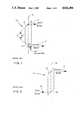
- FIGS. 1 and 2are schematic diagrams of prior art prisms of the type with which the invention may be practiced
- FIG. 3is a perspective view of a folding prism mounting assembly embodying the invention.
- FIGS. 4 and 5are transverse sections of the mounting assembly taken on lines 4--4 and 5--5, respectively, on FIG. 3.
- FIG. 6is a perspective view of the stud and nut showing details of construction.
- FIGS. 7 and 8are schematic representations of the mounting assembly shown in FIG. 5 illustrating an optical alignment adjustment along a first axis.
- FIGS. 9 and 10are schematic front and side views of the mounting assembly showing an optical alignment adjustment along a second axis perpendicular to the first axis.
- FIGS. 11 and 12are schematic top views of the mounting assembly showing an optical alignment adjustment along a third (longitudinal) axis perpendicular to the first and second axes.
- FIGS. 1 and 2show elongated optical components 10 and 12 typical of those with which the invention may be practiced with advantage.
- Component 10is a folding prism having a longitudinal axis 13 and opposite end surfaces 14 and 15 formed along perpendicular planes.
- Component 10may be either a solid block of glass as shown with surfaces 14 and 15 being coated to provide beam deflection or, alternatively, may support a frame holding two mirrors oriented to produce the same effect.
- An input optical beam 16 incident on surface 14is reflected 90° and propagates internally along axis 13 to surface 15 where it is again reflected 90° as output beam 17 from the prism in a direction parallel to but opposite from that of input beam 16.
- periscope prismis a similarly constructed periscope prism having a longitudinal axis 18 and plane parallel end surfaces 19 and 20 formed at 45° angles to axis 18.
- An input beam 16' incident on surface 20is reflected upwardly, as viewed, along axis 18 to surface 19 which reflects it as output beam 17' parallel to and in the same direction of propagation as input beam 16'.
- optical component 21, shown in FIGS. 3, 4 and 5by way of example as a solid cylindrical folding prism similar to component 10 in FIG. 1, has a longitudinal central axis 22 and is secured to a support platform 23 by a mounting assembly 24.
- Assembly 24has a base plate 25 secured to platform 23 by screws 26 and 27.
- Base plate 25also has a central opening 29 larger than the diameter of component 21 which extends through opening 29 and projects from opposite sides of assembly 24.
- Joint 30comprises an annular collar 31 having a convex spherically shaped external surface 32 and secured by a suitable adhesive 33 to the central portion of component 21, and clamp parts 34 and 35 having concave spherically shaped inwardly facing surfaces 36 and 37, respectively, adjacent to collar 32.
- the spherically shaped surfaces of collar 32 and of clamp parts 34 and 35preferably have the same radius R.
- Clamp part 34is integral with and depends from base plate 25.
- Clamp part 35is a separate piece disposed below plate 25 opposite from part 34 and movable relative thereto.
- the central portion of stud 39comprises an integral ring 45 having an internal diameter slightly larger than that of component 21 and disposed to circumscribe the latter, as shown.
- component 21may comprise a hollow frame which supports dielectric mirrors at opposite ends to provide the desired beam deflection.
- the entering and exiting optical beams 16 and 17should initially be located in nominally correct positions. This implies that initially the beam propagation axes are parallel to within approximately 5 milliradians in angle and are located in space to about 0.010 inches of the desired value.
- Mounting assembly 24is installed with component 21 in the nominally vertical position as shown in FIG. 7 and is positioned using lateral translation on platform 23 to locate component axis 22 between the positions of the slightly laterally misaligned apertures through which the input and output beams enter and exit the region of component 22.
- the misalignment of the aperturesis greatly exaggerated in the drawing for clarity of description. The following three paragraphs describe the manner in which the three desired optical alignments [i.e., translational beam alignment in the vertical and horizontal directions, and angular beam alignment in the horizontal direction] can be achieved through essentially decoupled motions of the adjustable optical mount.
- component 21is rotated clockwise in the direction of angle ⁇ , see FIG. 8, about axis 45 (which axis is perpendicular to axis 22) until axis 22 is coincident with the centers of the entrance and exit apertures as shown in the drawing. This provides the required lateral translational adjustment to compensate for aperture offsets.
- component 21is rotated about axis 46 (perpendicular to axis 22) in the direction of angle ⁇ , see FIGS. 9 and 10.
- the effect of this movementis to bring the output beam to the desired lateral position.
- This adjustmentis possible because the net vertical offset of component 21 depends on movement in the direction of angle ⁇ . It should be noted that the extent of the offset variation of this angle depends on the particular point chosen as the center of rotation of the ball joint, so that greater or lesser degrees of resolution can be achieved depending on the rotation point chosen.
- component 21may be rotated about its axis 22 in the direction of angle ⁇ as shown in FIGS. 11 and 12. Since component 21 is never tilted far from the vertical, the effect of this adjustment is to produce angular motion of output beam 17 relative to input beam 16. This provides compensation for any lateral angular misalignment between the two beams. The vertical misalignment in angle due to this motion is insignificant.
Landscapes
- Physics & Mathematics (AREA)
- General Physics & Mathematics (AREA)
- Optics & Photonics (AREA)
- Astronomy & Astrophysics (AREA)
- Mounting And Adjusting Of Optical Elements (AREA)
Abstract
Description
Claims (5)
Priority Applications (1)
| Application Number | Priority Date | Filing Date | Title |
|---|---|---|---|
| US07/179,612US4826304A (en) | 1988-04-11 | 1988-04-11 | Adjustable optical mounting assembly |
Applications Claiming Priority (1)
| Application Number | Priority Date | Filing Date | Title |
|---|---|---|---|
| US07/179,612US4826304A (en) | 1988-04-11 | 1988-04-11 | Adjustable optical mounting assembly |
Publications (1)
| Publication Number | Publication Date |
|---|---|
| US4826304Atrue US4826304A (en) | 1989-05-02 |
Family
ID=22657281
Family Applications (1)
| Application Number | Title | Priority Date | Filing Date |
|---|---|---|---|
| US07/179,612Expired - LifetimeUS4826304A (en) | 1988-04-11 | 1988-04-11 | Adjustable optical mounting assembly |
Country Status (1)
| Country | Link |
|---|---|
| US (1) | US4826304A (en) |
Cited By (10)
| Publication number | Priority date | Publication date | Assignee | Title |
|---|---|---|---|---|
| US4964712A (en)* | 1988-05-31 | 1990-10-23 | Anderson Allen J | Wide-view horizontal vehicle safety mirror |
| US6061190A (en)* | 1999-03-11 | 2000-05-09 | Optics For Research | Devices for holding optical components at fixed positions |
| US6244086B1 (en)* | 2000-02-14 | 2001-06-12 | Ultra Dent Tools | Hand tool alignment device and method |
| US20020152627A1 (en)* | 2001-03-30 | 2002-10-24 | Klaus-Dieter Klein | Adjusting apparatus for devices and for setting adjustments |
| US20020171952A1 (en)* | 2001-04-12 | 2002-11-21 | Ulrich Weber | Apparatus for tilting a carrier for optical elements |
| US20040067014A1 (en)* | 2002-10-04 | 2004-04-08 | Hollars Dennis R. | Miniature optical multiplexer/de-multiplexer DWDM device, and method of aligning components thereof |
| US20040201909A1 (en)* | 2001-07-26 | 2004-10-14 | Alexander Kohl | Objective, particularly a projection objective for use in semiconductor lithography |
| US20050134972A1 (en)* | 2003-12-23 | 2005-06-23 | Jens Kugler | Replacement apparatus for an optical element |
| US20050174650A1 (en)* | 2002-04-30 | 2005-08-11 | Frank Melzer | Lighting system, particularly for use in extreme ultraviolet (euv) lithography |
| US20110014799A1 (en)* | 2008-04-03 | 2011-01-20 | Carl Zeiss Smt Ag | Projection illumination system for euv microlithography |
Citations (10)
| Publication number | Priority date | Publication date | Assignee | Title |
|---|---|---|---|---|
| US1161995A (en)* | 1910-06-15 | 1915-11-30 | Harry H Styll | Observation-glass. |
| US2130006A (en)* | 1935-02-04 | 1938-09-13 | Gundlach Rudolf | Periscope for armored vehicles |
| DE667340C (en)* | 1938-11-09 | Oesterr Ung Optische Anstalt C | Storage of optical viewing devices on armored vehicles | |
| US3049972A (en)* | 1961-04-19 | 1962-08-21 | Ernest Leitz Canada Ltd | Binocular with improved system of optical adjustment |
| US3509792A (en)* | 1968-04-18 | 1970-05-05 | Walter Ruf | Ball mount,particularly for armored vehicles |
| US3517554A (en)* | 1968-05-20 | 1970-06-30 | Uniroyal Inc | Safety sight glass |
| US3796478A (en)* | 1970-07-07 | 1974-03-12 | Rheinstahl Henschel Ag | Optical device and support in a vehicle |
| US4088396A (en)* | 1976-09-02 | 1978-05-09 | Ardel Kinamatic | Optical mount with independently orthogonally adjustable element |
| US4284326A (en)* | 1979-03-29 | 1981-08-18 | Werkzeugmaschinenfabrik Oerlikon-Buhrle Ag | Apparatus for eliminating external weather effects from the objective lens system of an aiming periscope installed at an armed vehicle |
| US4655548A (en)* | 1984-10-22 | 1987-04-07 | Grumman Aerospace Corporation | Multi-degree of freedom mount |
- 1988
- 1988-04-11USUS07/179,612patent/US4826304A/ennot_activeExpired - Lifetime
Patent Citations (10)
| Publication number | Priority date | Publication date | Assignee | Title |
|---|---|---|---|---|
| DE667340C (en)* | 1938-11-09 | Oesterr Ung Optische Anstalt C | Storage of optical viewing devices on armored vehicles | |
| US1161995A (en)* | 1910-06-15 | 1915-11-30 | Harry H Styll | Observation-glass. |
| US2130006A (en)* | 1935-02-04 | 1938-09-13 | Gundlach Rudolf | Periscope for armored vehicles |
| US3049972A (en)* | 1961-04-19 | 1962-08-21 | Ernest Leitz Canada Ltd | Binocular with improved system of optical adjustment |
| US3509792A (en)* | 1968-04-18 | 1970-05-05 | Walter Ruf | Ball mount,particularly for armored vehicles |
| US3517554A (en)* | 1968-05-20 | 1970-06-30 | Uniroyal Inc | Safety sight glass |
| US3796478A (en)* | 1970-07-07 | 1974-03-12 | Rheinstahl Henschel Ag | Optical device and support in a vehicle |
| US4088396A (en)* | 1976-09-02 | 1978-05-09 | Ardel Kinamatic | Optical mount with independently orthogonally adjustable element |
| US4284326A (en)* | 1979-03-29 | 1981-08-18 | Werkzeugmaschinenfabrik Oerlikon-Buhrle Ag | Apparatus for eliminating external weather effects from the objective lens system of an aiming periscope installed at an armed vehicle |
| US4655548A (en)* | 1984-10-22 | 1987-04-07 | Grumman Aerospace Corporation | Multi-degree of freedom mount |
Cited By (25)
| Publication number | Priority date | Publication date | Assignee | Title |
|---|---|---|---|---|
| US4964712A (en)* | 1988-05-31 | 1990-10-23 | Anderson Allen J | Wide-view horizontal vehicle safety mirror |
| US6061190A (en)* | 1999-03-11 | 2000-05-09 | Optics For Research | Devices for holding optical components at fixed positions |
| US6244086B1 (en)* | 2000-02-14 | 2001-06-12 | Ultra Dent Tools | Hand tool alignment device and method |
| US20020152627A1 (en)* | 2001-03-30 | 2002-10-24 | Klaus-Dieter Klein | Adjusting apparatus for devices and for setting adjustments |
| US7082693B2 (en) | 2001-03-30 | 2006-08-01 | Carl Zeiss Smt Ag | Adjusting apparatus for devices and for setting adjustments |
| US7014328B2 (en)* | 2001-04-12 | 2006-03-21 | Carl Zeiss Smt Ag | Apparatus for tilting a carrier for optical elements |
| US20020171952A1 (en)* | 2001-04-12 | 2002-11-21 | Ulrich Weber | Apparatus for tilting a carrier for optical elements |
| US20040201909A1 (en)* | 2001-07-26 | 2004-10-14 | Alexander Kohl | Objective, particularly a projection objective for use in semiconductor lithography |
| US7123427B2 (en) | 2001-07-26 | 2006-10-17 | Carl Zeiss Smt Ag | Objective, particularly a projection objective for use in semiconductor lithography |
| US7196841B2 (en) | 2002-04-30 | 2007-03-27 | Carl Zeiss Smt Ag | Lighting system, particularly for use in extreme ultraviolet (EUV) lithography |
| US20050174650A1 (en)* | 2002-04-30 | 2005-08-11 | Frank Melzer | Lighting system, particularly for use in extreme ultraviolet (euv) lithography |
| US20040067014A1 (en)* | 2002-10-04 | 2004-04-08 | Hollars Dennis R. | Miniature optical multiplexer/de-multiplexer DWDM device, and method of aligning components thereof |
| US20090168207A1 (en)* | 2003-12-23 | 2009-07-02 | Carl Zeiss Smt Ag | Replacement Apparatus for an Optical Element |
| US7265917B2 (en) | 2003-12-23 | 2007-09-04 | Carl Zeiss Smt Ag | Replacement apparatus for an optical element |
| US20070297074A1 (en)* | 2003-12-23 | 2007-12-27 | Jens Kugler | Replacement apparatus for an optical element |
| US7515363B2 (en) | 2003-12-23 | 2009-04-07 | Carl Zeiss Smt Ag | Replacement apparatus for an optical element |
| US20050134972A1 (en)* | 2003-12-23 | 2005-06-23 | Jens Kugler | Replacement apparatus for an optical element |
| US7768723B2 (en) | 2003-12-23 | 2010-08-03 | Carl Zeiss Smt Ag | Replacement apparatus for an optical element |
| US20100271716A1 (en)* | 2003-12-23 | 2010-10-28 | Carl Zeiss Smt Ag | Replacement apparatus for an optical element |
| US7995296B2 (en) | 2003-12-23 | 2011-08-09 | Carl Zeiss Smt Gmbh | Replacement apparatus for an optical element |
| US8488261B2 (en) | 2003-12-23 | 2013-07-16 | Carl Zeiss Smt Gmbh | Replacement apparatus for an optical element |
| US8902519B2 (en) | 2003-12-23 | 2014-12-02 | Carl Zeiss Smt Gmbh | Replacement apparatus for an optical element |
| US9081296B2 (en) | 2003-12-23 | 2015-07-14 | Carl Zeiss Smt Gmbh | Replacement apparatus for an optical element |
| US20110014799A1 (en)* | 2008-04-03 | 2011-01-20 | Carl Zeiss Smt Ag | Projection illumination system for euv microlithography |
| US8710471B2 (en) | 2008-04-03 | 2014-04-29 | Carl Zeiss Smt Gmbh | Projection illumination system for EUV microlithography |
Similar Documents
| Publication | Publication Date | Title |
|---|---|---|
| US7035025B2 (en) | Compact precision beam manipulators | |
| US4060315A (en) | Precision mirror mount | |
| US8016438B2 (en) | Spherical mirror mount | |
| US10670825B2 (en) | Mounting devices with integrated alignment adjustment features and locking mechanisms | |
| US4826304A (en) | Adjustable optical mounting assembly | |
| US5880894A (en) | Method and system for mounting optical elements | |
| KR20150022718A (en) | Optical subassembly with a mount with connection units of directed flexibility | |
| US6570721B2 (en) | Optomechanical mount for precisely steering/positioning a light beam | |
| KR102577850B1 (en) | Monolithic Flexure Hinge Mount for Optical section | |
| US5798879A (en) | Stress-free, adjustable optical support | |
| US4448385A (en) | Stable alignment mechanism for laser mirrors | |
| US7224871B2 (en) | Ultra stable optical element x,y, positioning unit for use in harsh environments | |
| US6296362B1 (en) | Vibration hardened mirror mount with alignment friendly locking | |
| US7073952B2 (en) | Stable mechanical devices for precision optical alignment and packaging | |
| US4869583A (en) | Optical beam precision positioner | |
| JP7292541B2 (en) | Mirror support mechanism and optical device | |
| US7321706B2 (en) | Optical fiber coupler | |
| US5959789A (en) | One piece beam angle adjustment element | |
| US6590723B1 (en) | Optical instrument mount | |
| JPH0361925B2 (en) | ||
| US6550925B1 (en) | Mirror support | |
| US4480895A (en) | Adjustable reflector apparatus | |
| JPS63502865A (en) | laser | |
| Carlson et al. | Optomechanical design of the Micro-Arcsecond Metrology testbed interferometer | |
| RU2141682C1 (en) | Device for adjustment of optical instruments |
Legal Events
| Date | Code | Title | Description |
|---|---|---|---|
| AS | Assignment | Owner name:GTE GOVERNMENT SYYSTEMS CORPORATION Free format text:ASSIGNMENT OF ASSIGNORS INTEREST.;ASSIGNORS:GUCH, STEVE JR.;SMITH, JOHN J.;REEL/FRAME:004866/0813 Effective date:19880406 Owner name:GTE GOVERNMENT SYYSTEMS CORPORATION,CONNECTICUT Free format text:ASSIGNMENT OF ASSIGNORS INTEREST;ASSIGNORS:GUCH, STEVE JR.;SMITH, JOHN J.;REEL/FRAME:004866/0813 Effective date:19880406 Owner name:GTE GOVERNMENT SYSTEMS CORPORATION, CONNECTICUT Free format text:ASSIGNMENT OF ASSIGNORS INTEREST;ASSIGNORS:GUCH, STEVE, JR.;SMITH, JOHN J.;REEL/FRAME:004866/0813 Effective date:19880406 | |
| STCF | Information on status: patent grant | Free format text:PATENTED CASE | |
| FEPP | Fee payment procedure | Free format text:PAYOR NUMBER ASSIGNED (ORIGINAL EVENT CODE: ASPN); ENTITY STATUS OF PATENT OWNER: LARGE ENTITY | |
| FEPP | Fee payment procedure | Free format text:PAYER NUMBER DE-ASSIGNED (ORIGINAL EVENT CODE: RMPN); ENTITY STATUS OF PATENT OWNER: LARGE ENTITY Free format text:PAYOR NUMBER ASSIGNED (ORIGINAL EVENT CODE: ASPN); ENTITY STATUS OF PATENT OWNER: LARGE ENTITY | |
| FPAY | Fee payment | Year of fee payment:4 | |
| FEPP | Fee payment procedure | Free format text:PAYER NUMBER DE-ASSIGNED (ORIGINAL EVENT CODE: RMPN); ENTITY STATUS OF PATENT OWNER: LARGE ENTITY Free format text:PAYOR NUMBER ASSIGNED (ORIGINAL EVENT CODE: ASPN); ENTITY STATUS OF PATENT OWNER: LARGE ENTITY | |
| REMI | Maintenance fee reminder mailed | ||
| FPAY | Fee payment | Year of fee payment:8 | |
| SULP | Surcharge for late payment | ||
| FEPP | Fee payment procedure | Free format text:PAYER NUMBER DE-ASSIGNED (ORIGINAL EVENT CODE: RMPN); ENTITY STATUS OF PATENT OWNER: LARGE ENTITY | |
| AS | Assignment | Owner name:GENERAL DYNAMICS GOVERNMENT SYSTEMS CORPORATION, M Free format text:CHANGE OF NAME;ASSIGNOR:GTE GOVERNMENT SYSTEMS CORPORATION;REEL/FRAME:010731/0156 Effective date:19990908 | |
| FPAY | Fee payment | Year of fee payment:12 |