US4826289A - Day/night rearview mirror assembly - Google Patents
Day/night rearview mirror assemblyDownload PDFInfo
- Publication number
- US4826289A US4826289AUS07/092,450US9245087AUS4826289AUS 4826289 AUS4826289 AUS 4826289AUS 9245087 AUS9245087 AUS 9245087AUS 4826289 AUS4826289 AUS 4826289A
- Authority
- US
- United States
- Prior art keywords
- stop
- case
- mirror
- actuator
- pivot
- Prior art date
- Legal status (The legal status is an assumption and is not a legal conclusion. Google has not performed a legal analysis and makes no representation as to the accuracy of the status listed.)
- Expired - Lifetime
Links
Images


Classifications
- B—PERFORMING OPERATIONS; TRANSPORTING
- B60—VEHICLES IN GENERAL
- B60R—VEHICLES, VEHICLE FITTINGS, OR VEHICLE PARTS, NOT OTHERWISE PROVIDED FOR
- B60R1/00—Optical viewing arrangements; Real-time viewing arrangements for drivers or passengers using optical image capturing systems, e.g. cameras or video systems specially adapted for use in or on vehicles
- B60R1/02—Rear-view mirror arrangements
- B60R1/08—Rear-view mirror arrangements involving special optical features, e.g. avoiding blind spots, e.g. convex mirrors; Side-by-side associations of rear-view and other mirrors
- B60R1/083—Anti-glare mirrors, e.g. "day-night" mirrors
- B60R1/086—Anti-glare mirrors, e.g. "day-night" mirrors using a mirror angularly movable between a position of use and a non-glare position reflecting a dark field to the user, e.g. situated behind a transparent glass used as low-reflecting surface; Wedge-shaped mirrors
Definitions
- This inventionrelates to rearview mirrors for vehicles and, more particularly, to day/night rearview mirror assemblies which are shiftable between a high reflectivity day position and a reduced reflectivity night position whereby undesired, distracting glare from behind the vehicle visible to the driver in the rearview mirror is reduced and/or eliminated in the night position.
- the present inventionrelates to an improved day/night rearview mirror assembly in which shifting between the day and night positions is precisely controlled while annoying movement between the day and night positions during adjustment of the gross position of the mirror is reduced. Also, resistance to impact and bending is improved, and assembly weight and manufacturing costs are reduced while manufacturing assembly is facilitated.
- Conventional day/night rearview mirrorsemploy a variety of systems to control movement between the high and low reflectivity positions.
- Such assembliesnormally include a toggle member or other actuator to which is pivotally mounted the rearview mirror case and prism element.
- a cam or overcenter-type lever operatoris used to pivot the case and prism with respect to the actuator.
- the actuatoris normally mounted on a ball joint or other support extending to a fixed member in the vehicle.
- a common method for controlling toggle/actuator movement in mirror casesis to limit their travel by contact with the rear side of the prism mirror element when mounted in the case.
- the final position of the mirror elementis not precisely the same in each assembly.
- the rear surface of the mirror elementmust be uniform. When the mirror elements are slightly mispositioned or the rear surface is irregular, pronounced inaccuracy in the day/night shifted positions of the assembly occurs because of the compound mispositioning of the assembled elements or irregular surfaces.
- a related problem to that of undesirable shift between day and night positions when adjusting the mirror in higher temperaturesis that of inconsistent pressure or pivot force when moving the mirror assembly between its day and night positions.
- inconsistent pressure or pivot forcewhen moving the mirror assembly between its day and night positions.
- the present inventionwas conceived in recognition of and as a solution for the above and other related problems.
- the present inventionprovides a manually operated day/night rearview mirror assembly shiftable between a substantially full reflectivity day position and a reduced reflectivity night position to reduce unwanted glare from the mirror to the driver's eyes.
- the assemblyprovides improved control of the day and night positions for the assembly, reduces annoying shifting during gross mirror position adjustment, and provides reduced weight and manufacturing cost while manufacture of the assembly is facilitated and simplified.
- the inventionis a day/night rearview mirror assembly for vehicles comprising a mirror case, a prismatic mirror element having nonparallel, generally planar front and back surfaces supported and retained in the case and an actuator assembly mounted on the case for shifting the case and mirror element between a predetermined reflectivity day position and a reduced reflectivity night position.
- the actuator assemblyincludes lateral side edges and shafts and shaft supports for supporting the actuator assembly in the case.
- the caseincludes at least a pair of spaced ribs for reinforcement, the ribs extending generally transverse to the shafts.
- a pair of upstanding stop members on the case interiorlimit shifting movement of the actuator assembly toward the mirror element. One of said stop members is positioned between each lateral side edge of the actuator assembly and one of the ribs.
- the upstanding stop membersare spaced from but braced against the internal ribs within the case. Inclined upper surfaces on the stop members engage correspondingly sloped surfaces on the toggle actuator to provide a camming action facilitating insertion of the toggle in the molded case with minimal deflection.
- the stop membersare spaced more closely together than the ribs or the support shafts for the actuator allowing the toggle actuator adjacent the stop members to be narrower in width thereby saving on material costs and weight.
- the caseis provided with spaced support members for receiving the shafts extending from the actuator assembly for moving the case between day and night positions.
- Support members adjacent the top of the caseinclude shaft receiving spaces and flanges extending over the shaft receiving spaces to define access openings to the support spaces which open downwardly toward the bottom of the case and prevent the shaft means from moving toward the mirror element even upon severe impact such as during an accident.
- ramp membersare provided on support walls adjacent the support members for resisting withdrawal of the shaft means from the shaft receiving spaces. Those ramp members may include inclined surfaces for deflection of the ramp members and supporting walls during assembly.
- the upper toggle membermay include a downwardly extending lip adjacent the pivot surface which engages the lower pivot member of the assembly.
- the lipextends over a spring bar on the pivot member between the spring bar and the mirror element to help prevent movement of the pivot member toward the mirror element and to aid in assembling the mirror assembly.
- the stop membersare positioned to require longer movement distance to move the assembly from its day position to the night position than is required to move the case out of its night position.
- 60% of the overcenter actuator pivot lever travelis required to move the assembly out of its day position. This prevents undesired day/night shifting of the assembly when the gross position of the mirror assembly is adjusted by a driver on its support.
- a toggle actuatormay include an improved reinforcement structure including a ball joint clamping plate cooperating with a molded polymeric reinforcing rib on the actuator to reduce the number of overall parts as well as actuator assembly weight and manufacturing cost.
- the present inventionprovides the advantages of precise control of the day/night viewing positions and shift angles via stop surfaces which are independently positioned from other structures within the one component case for proper control and function.
- the stop surfacesare preferably included on the molded case such that they may be controlled in one mold for accuracy. No dependence on assembled parts such as the independently positioned mirror prism is required.
- the position of the prismcan vary from case to case and cause compounded inaccuracies after assembly. Hence, control of the day/night position is self-contained within the mirror case.
- stop membersare strong and stable yet allow easy installation of the actuator assembly with minimum deflection through the use of cooperating camming surfaces.
- the assemblymay also avoid annoying flip or shifting between day and night viewing positions when the gross mirror position is adjusted by requiring greater movement of the pivot lever to move the assembly out of its day position than when the assembly is moved from its night position. Since the majority of mirror position adjustment for different driver sizes is done with the mirror in its day viewing position, undesired shifting is significantly reduced.
- the inventionprovides improved resistance to impact breakage such as during accidents and to bending caused by such impact.
- the pivot supports for the actuator assembly within the caseare closed toward the mirror element and open downwardly toward the case bottom. Hence, movement of the actuator even if forced in the direction of the mirror element is prevented thereby reducing disassembly, fracture or breakage of the mirror glass and consequent injury to occupants within a vehicle. Further, withdrawal of the actuator support shafts from the support members within the case is further restricted by the ramp members.
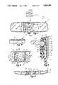
- FIG. 1is a front elevation of a first embodiment of the day/night rearview mirror assembly of the present invention
- FIG. 2is a sectional side elevation of the complete mirror assembly taken along plane II--II of FIG. 1;
- FIG. 3is a fragmentary front elevation of the molded, one piece mirror case of the assembly shown in FIG. 1 with the actuator assembly removed;
- FIG. 4is a fragmentary, bottom plan view of the mirror case portion shown in FIG. 3;
- FIG. 5is a sectional view of the mirror case taken along plane V--V of FIG. 3;
- FIG. 6is a sectional view of the mirror case with mirror prism element installed but omitting the actuator assembly and taken along plane VI--VI of FIG. 3;
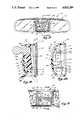
- FIG. 7is a front elevation of the actuator toggle member of the mirror assembly of FIG. 1;
- FIG. 8is a left side elevation of the toggle member of FIG. 7;
- FIG. 9is a bottom plan view of the toggle member of FIGS. 7 and 8;
- FIG. 10is a sectional view of the toggle member taken along plane X--X of FIG. 8;
- FIG. 11is a front elevation of the actuator pivot lever of the mirror assembly of FIG. 1;
- FIG. 12is a top plan view of the pivot lever of FIG. 11;
- FIG. 13is a side elevation of the ball stay cup of the mirror assembly of FIG. 1;
- FIG. 14is a top plan view of the ball stay cup of FIG. 13;
- FIG. 15is a fragmentary, enlarged side sectional view of the lower portion of the assembly of FIG. 2 showing the mirror assembly in day viewing position;
- FIG. 16is a side sectional view of the mirror assembly schematically illustrating the angular travel distances for the actuator toggle and pivot member
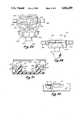
- FIG. 17is a front elevation of a second embodiment of the day/night rearview mirror assembly of the present invention showing the prismatic mirror element broken away and the actuator assembly mounted therein;
- FIG. 18is a sectional side elevation of the mirror assembly taken along plane XVIII--XVIII of FIG. 17;
- FIG. 19is a fragmentary front elevation of the molded, one piece mirror case of the assembly shown in FIGS. 17 and 18 with the toggle actuator assembly removed;
- FIG. 20is a sectional side elevation of the mirror case in FIG. 19 taken along plane XX--XX of FIG. 19;
- FIG. 21is a fragmentary sectional view of the mirror case of FIGS. 17-20 taken along plane XXI--XXI of FIG. 19;
- FIG. 22is a fragmentary top view of the mirror case portion shown in FIGS. 19 and 21 with portions broken away;
- FIG. 23is a front elevation of the actuator toggle member of the mirror assembly of FIG. 17;
- FIG. 24is a top plan view of the toggle member of FIG. 23;
- FIG. 25is a sectional view of the toggle member of FIGS. 23 and 24 taken along plane XXV--XXV of FIG. 23;
- FIG. 26is a back elevation of the actuator toggle member of FIGS. 23-25;
- FIG. 27is a front elevation of the actuator pivot lever of the mirror assembly of FIG. 17;
- FIG. 28is a top plan view of the pivot lever of FIG. 27.
- FIG. 29is a sectional side elevation of the pivot lever of FIGS. 27 and 28 taken along plane XXIX--XXIX of FIG. 27.
- FIGS. 1-16illustrate a first embodiment 10, of the day/night rearview mirror assembly.
- mirror assembly 10generally includes a molded, thermoplastic mirror case 12 having a length greater than its width.
- a two-part overcenter-type toggle actuator assembly 70is pivotally mounted in the center section of case 12.
- Actuator assembly 70is adapted to receive some type of pivotal mounting from a fixed vehicle support such as breakaway support arm 14 having ball member 15 at its end.
- Breakaway support arm 14may be of various types and forms no part of the present invention.
- the upper part of the two-part actuator assembly 70includes a reinforced toggle member 72 pivotally received in spaced pivot supports 26, 28 molded integrally within case 12 and a separate, molded pivot lever or member 74.
- Pivot lever 74has an integral spring bar 76 resiliently engaging the bottom of toggle member 72 and is pivotally supported in a separate set of spaced pivot supports 32, 34 in the lower, center portion of mirror case 12.
- Actuator assembly 70is received within the interior of case 12 between rear wall 18 and the rear side of a prismatic reflective mirror element 16.
- Pivotal movement of the extending tab 78 of pivot lever 74 generally in a direction perpendicular to the general plane of mirror element 16causes overcenter action of the two-part actuator assembly 70 and shifting of mirror case 12 and, thus, the position of the reflective mirror element 16, for day and night viewing positions as explained more fully hereinafter.
- molded case 12is generally of a hollow construction having a shell of thermoplastic material, such as polypropylene, a back wall 18 spaced behind mirror element 16, a continuous peripheral sidewall 19, integral, upstanding mirror case support walls or ribs 20, integral, upstanding support ribs 22 and structural cross members or braces 24 extending between walls 20 and ribs 22.
- Walls or ribs 20are higher than ribs 22 (FIG. 6).
- Spaced upper pivot shaft supports 26, 28are molded integrally with the case between top wall 30 and case back 18 and are reinforced by ribs 22 which connect them in a direction transverse to the longitudinal direction of case 12 and the pivot shafts on actuator assembly 70.
- Lower shaft pivot supports 32, 34extend between back wall 18 and bottom wall 36 and are likewise reinforced by ribs 22.
- a molded mirror element retaining rim 38extends around the forward edge of continuous peripheral wall 19 on case 12 and defines an opening to the hollow interior of the case. That opening normally is positioned to face rearwardly within the vehicle when mounted on support 14 as shown in FIGS. 1 and 2.
- Bottom wall 36 of case 12includes a generally rectangular opening 40 which provides space through which the pivot tab 78 of pivot lever 74 extends when actuator assembly 70 is mounted within the case.
- a circular aperture 42is provided through the upper portion of the center part of back wall 18 through which the support arm 14 and ball member 15 are received (FIGS. 2 and 3).
- an elongated raised area 44extends inwardly from the inside surface of back wall 18 to provide a contact surface for the actuator assembly to help control its pivotal movement and position the toggle member 72 in its night position as will be explained hereinafter.
- Mirror element 16is preferably a transparent, prismatic element of glass, plastic or the like having nonparallel front and back surfaces 17a, 17b, respectively (FIGS. 2 and 6).
- the rear surface 17bhas a thin layer 21 of reflective material such as metallic silver, chrome or the like preferably covered by a resilient, impressionable, protective, anti-scattering layer 23 of a resinous material such as polyvinyl chloride (PVC) applied in plastisol form followed by heat curing.
- PVCpolyvinyl chloride
- upper and lower pivot shaft support members 26, 28 and 32, 34are molded integrally with case 12 on the inside surface of case back 18 between support walls 20.
- Upper shaft support members 26, 28are spaced laterally from and aligned with one another on case back 18.
- Each support member 26, 28includes a pair of parallel support ribs or walls 26a, 26b and 28a, 28b respectively. These support ribs are identical and include a circular shaft receiving space 46 (FIG. 6) which opens toward the front of the mirror case and toward prismatic mirror element 16.
- a slanted surface 48is included on each support wall to direct the actuator support shafts into the shaft receiving spaces 46 when the actuator is installed and pressed into the supports.
- Support walls 26a, 26b, 28a, 28bare respectively connected by transverse ribs 27, 29 (FIG. 3) each of which includes a retaining lip 50 allowing the actuator support shafts to be snapped into and retained in receiving spaces 46.
- the lower shaft supports 32, 34each include parallel support walls 32a, 32b, 34a, 34b which include shaft receiving spaces 52 which are parallel and aligned with one another across the case.
- Support walls 32a, 32b, 34a, 34bare respectively joined by transverse ribs 33, 35.
- the transverse ribsinclude angled lead-in surfaces 54 directing the shafts into the receiving spaces 52, and lips 56 which retain the shafts in position in like manner to lips 50.
- Supports 26, 28 and 32, 34are interconnected by upstanding support ribs 22 which are integral with the inside surface of the case back 18 (FIGS. 3 and 6). These ribs, along with support walls 20, rigidify the central, actuator support area of the case and hold the support members at their precise spacing to allow proper actuator pivot control over the mirror position. As will be seen in FIG. 3, however, supports 32, 34 are spaced slightly closer together than upper supports 26, 28 due to the tapered design of the actuator shown in FIGS. 1 and 7-12.
- the actuator support area of the interior of case 12also includes a pair of laterally spaced upstanding stop members 60, 62 which extend outwardly toward mirror element 16 from the inside surface of case back 18.
- Stop members 60, 62are mirror images of one another and each include an outwardly extending wall 64 having a laterally inwardly extending flange 66 at its outer end.
- the outer surface of flange 66is angled downwardly and inwardly to provide a camming or deflecting surface which cooperates with a surface on the underside of actuator toggle member 72 when pressed into the case during assembly.
- each stop memberincludes a downwardly inclined brace 69 extending between upstanding walls 64 and rib 22 to provide lateral rigidity for the stop members to insure proper positioning and control of the actuator assembly. Braces 69 extend to a position slightly below the top of stop members 60, 62 which allows the top portion of the stop members to be deflected slightly or cammed outwardly more easily during insertion of the actuator toggle member.
- actuator toggle member 72includes a body 80 preferably molded from polypropylene or acetal resin including front and back surfaces 82, 84 and an upstanding ridge 85 which outlines the edge of body 80 and defines lateral side edges 86, 88 and bottom edge 90. Edges 86, 88 are spaced to fit between and immediately adjacent support members 26, 28 to prevent lateral movement of toggle 72 in case 12. Adjacent the top edge of body 80 a pair of cylindrical support shafts 92, 94 extend laterally outwardly perpendicular to side edges 86, 88 and are concentric and parallel with one another and to bottom edge 90.
- a reinforcing ridge 96extends parallel to the axis of cylindrical shafts 92 94 and includes a pair of laterally spaced recesses 98 formed therein and opening downwardly toward bottom edge 90.
- a recess 100 centered in the lower portion of ridge 96provides space for circular ball member receiving aperture 102 and surrounding recess 104 formed in the center portion of actuator toggle body 80.
- Slightly below ball member receiving aperture 102is a second aperture 106 adapted to receive a retaining bolt and nut for applying clamping friction pressure to a clamping plate as explained hereinafter.
- a downwardly extending flange 108having a downwardly opening, V-shaped pivot surface 110 adapted to engage the spring bar of lower, separate pivot member 74.
- An elongated contact surface 112(FIGS. 7-9), adapted to contact pad or surface 44 on the interior of the case back 18 to precisely position the actuator toggle body in its night position, is also included.
- each stop shoulder 114extends generally parallel to lateral side edges 86, 88 and perpendicular to the axis of shafts 92, 94 and includes a stop surface 116 which is positioned between front and back surfaces 82, 84 and slightly downwardly inclined to match the inclined stop surface 68 on the underside of flanges 66 on stop members 60, 62.
- Inclined lower surfaces 118angle downwardly and inwardly toward one another to mate with cam surfaces 67 on stop members 60, 62 to deflect those surfaces outwardly during installation of the toggle body member in the case 12.
- lower actuator pivot lever or pivot member 74includes a pivot body 75, spring bar 76 which is raised or spaced above the main body 75, and a downwardly extending tab lever 78 for manual actuation of the actuator assembly 70 within case 12.
- a pair of parallel, cylindrical pivot support shafts 77, 79extend outwardly from either side of body 75 and are adapted to fit in support shaft receiving spaces 52 of lower support members 32, 34.
- Spring bar 76has a rounded upper surface adapted to mate with V-shaped surface 110 on the bottom of toggle member 72.
- Ends 76a, 76b of bar 76are spaced to fit between and against the inside edges of transverse ribs 33, 35 and support members 32, 34 to prevent lateral movement of lever 74 in the case. Ends 76a, 76b are also rounded for easier insertion.
- the side surfaces of spring bar 76may be tapered inwardly toward one another to provide greater clearance with V-shaped surface 110 when pivot member 74 is pivoted to its day position as shown in FIG. 15.
- mirror assembly 10also includes a generally frusto conical ball, split ring stay cup 120 also preferably molded from polypropylene or acetal resin.
- Cup 120includes a relieved area or opening 122, an annular ridge 124, and locating flanges 126 and 130.
- a ball member receiving opening 128extends through the cup.
- Locating flange 130is spaced opposite opening 122. Locating flanges 126 are adapted to be received in openings 105 formed on either side of locating member 107 molded in the recess 104 on actuator body member 80, while locating flange 130 is adapted to be received in recess 109 molded within recess 104.
- Ball member 15 on support arm 14is passed through opening 42 in back 18 of case 12 and for assembly with actuator toggle member 72.
- Ball stay cup 120is expanded slightly over the ball member after the ball member has been passed through opening 102 in toggle body member 80. Cup 120 is then located in recess 104 with locating flanges 126 and 130 received in recesses 105, 109.
- a molded polypropylene or acetal resin ball cap 135is then placed over the exposed end of ball member 15 followed by placing a metallic clamping plate 140 (FIGS. 1, 2 and 7) over-top ball cap 135.
- Clamping plate 140is generally triangular in shape and includes a central depression 142, a pair of laterally spaced upwardly extending ears 144 which are received in recesses 98 in ridge 96 when depression 142, is received over ball cap 135, and a lower fastener receiving aperture 146 (FIG. 2). Aperture 146 is aligned with opening 106 in actuator body 80 when depression 142 is received over ball cap 135.
- a retaining screw 148is passed through apertures 146 and 106 and is threaded through retaining nut 150 received in a hexagonal recess 152 on the rear side of actuator body 80.
- screw 148friction pressure of ball cap 135 is increased on ball 15 against cup 120 to hold assembly 10 in its proper adjusted position on arm 14.
- Clamp plate 140acts as a lever pivoting about ears 144 in recesses 98.
- actuator assembly 70is inserted in the center interior portion of case 12 by aligning shafts 92, 94 on actuator body 80 with support members 26 28 while pivot member 74 is nested with spring bar 76 within V-shaped pivot surface 110 and support shafts 77, 79 aligned with support members 32, 34.
- Actuator toggle 72 and pivot member 74are then pressed inwardly such that shafts 92, 94 and 77, 79 are snapped into shaft receiving spaces 46, 52 via camming surfaces 48, 54 and past lips 50, 56 for proper pivotal retention in the mirror case.
- surfaces 118 on toggle 72deflect stop members 60, 62 slightly outwardly via surfaces 67 to allow passage of toggle body 80 into place.
- Pivot member 74may then be grasped by tab lever 78 and rotated forwardly and rearwardly for overcenter-type pivot action with toggle 72 to provide day and night positions for the actuator assembly 70 within case 12.
- actuator toggle 72is pivoted forwardly and the rear reflective surface 17a, 21 of mirror element 16 is aligned with the driver's eyes for full reflectivity use in the day position.
- actuator toggle 72is pivoted rearwardly and case 12 and mirror element 16 are pivoted about ball member 15 such that the front, nonsilvered surface 17a of glass mirror element 16 is aligned with the driver's eyes for reduced reflectivity or night driving.
- the actuator toggle locationis defined by contact between stop surfaces 68 and 116 while in the night position the position is defined by contact between surfaces 44 and 112.
- the major adjustment position of the mirror assembly 10is controlled by positioning the mirror assembly on ball member 15 by the driver.
- the locations of stop surfaces 44, 68are positioned as shown in FIG. 16 to provide 60% of the travel from the rear or day position of tab lever 78 to the overcenter or centered position and 40% of the travel from the night position of tab lever 78 to the overcenter or centered position. For example, this corresponds to 3 degrees 14 minutes of angular movement of the case and mirror element about pivot shafts 92, 94 in the day position and 2 degrees 15 minutes of angular travel in the night position.
- tab lever 78moves through 34.5 degrees of travel from the day position to the centered position and only 26 degrees of angular travel from the night position to the centered position.
- the greater amount of travel required for the pivot member to the centered or overcenter position from the day positionprevents the assembly from moving from day to night position when the gross or major position of the mirror assembly is changed by the driver about ball member 15.
- screw 148is adjusted to provide tight clamping pressure on ball member 15
- rotation of the case assembly on ball member 15 by grasping the upper and lower edges of case 12 with the tab lever in the day positionwill avoid changing of the pivot member to the night position even if the toggle member pivots slightly on shafts 92, 94 during such rotating movement. This is because the friction pressure on ball member 15 is slightly greater than the force of spring bar 76 against pivot surface 110.
- pivot memberwith 50% of its travel from the center position toward both the day and night positions if desired. Also, other ratios of day to night travel can also be used.
- assembly 160includes a thermoplastic mirror case 162 preferably molded from polypropylene and having a length greater than its width.
- a two-part, overcenter-type toggle actuator assembly 240is pivotally mounted in the center section of case 162 including an actuator toggle member 242 and a separate pivot lever or member 280.
- actuator toggle member 242includes an internal, cast metal reinforcing member 244 having an integral ball member 246 extending outwardly therefrom which is adapted to be received in a mirror support arm of conventional variety to allow adjustment of the overall mirror assembly position.
- molded case 162is generally of hollow construction having a back wall 164 spaced behind the prismatic mirror element 166 which is substantially similar to element 16.
- Case 162also includes a continuous, peripheral sidewall 168 having top, bottom and end portions.
- integral, upstanding mirror case support walls or ribs 170extending transversely across the interior of the case generally perpendicular to the direction of longitudinal extension of the case.
- Integral ribs 172extend generally parallel to walls 170 but are of lesser height. Longitudinal bracing ribs 174, 175 extend between ribs 170 and 172.
- Ribs 174, 175strengthen the case back in the area of rear opening 176 through which ball member 246 passes from actuator toggle member 242. Opening 177 extends through the case back 164 and bottom peripheral sidewall 168 at the lower corner of the case to allow passage of the pivot member 280 when installed within the case as shown in FIG. 18.
- Support walls 170are reinforced on their outer sides by gussets 178 (FIG. 19) molded integrally between the case back and support walls in the area adjacent the pivot supports for the actuator assembly.
- upper pivot shaft supports 180, 182In the area between support walls/ribs 170 are laterally spaced upper pivot shaft supports 180, 182 and lower pivot shaft supports 184, 186. Each upper and lower pair of pivot supports 180, 184 and 182, 186 is interconnected by one of the integral bracing ribs 172 to maintain the supports at their proper spacing.
- Upper pivot shaft supports 180, 182differ from supports 26, 28 in embodiment 10 by each including a cover or front flange 188 extending over the support walls forming the support member in the area between the support member and prismatic mirror element 166.
- Flange 188covers the shaft receiving space 190 and prevents the shafts from the actuator assembly from moving forwardly toward the mirror element upon impact.
- Supports 180, 182do, however, open generally downwardly toward the bottom wall of the case 162 such that the actuator pivot shafts may be inserted from that direction under flange 188.
- Inclined or angled surfaces 192, 194 leading to shaft receiving space 190are provided on support members 180, 182 to guide the shaft members into place during assembly.
- Lower pivot shaft support members 184, 186are laterally spaced and aligned with one another and include a pair of parallel support walls defining a pivot shaft receiving space 196 opening at an angle toward the prismatic mirror element in a manner similar to supports 32, 34 in embodiment 10.
- a raised contact surface or pad 198 on the inner surface of case back 164is provided to contact and position the actuator toggle member in its night position as explained more fully below.
- the interior of the case in the center areaalso includes a pair of upstanding stop members 200, 202 extending outwardly toward the prismatic mirror element from the interior of the case back.
- Each stop memberis generally similar to stop members 60, 62 in embodiment 10 and includes an upstanding wall 204, a laterally extending flange 206 including an overhanging stop surface 208 and an upper cam or deflecting surface 210.
- stop members 200, 202are reinforced by gussets or triangular braces 212 which extend from the case back adjacent the inner surface of ribs 172 to the top of support wall 204 at the outer end of stop members 200, 202 as best seen in FIG. 21.
- Stop surfaces 208are angled downwardly toward the bottom peripheral wall of the case to match the angle of the stop surfaces on actuator toggle member 242 as described below.
- the inside surfaces of support walls 170each include inclined ramp members or shoulders 220 (FIGS. 19 and 20) which extend outwardly from adjacent the back wall of the case to the outer edge of walls/ribs 170.
- Ramp members 220include planar stop surfaces 222 facing the shaft receiving spaces 190, 196, respectively, and an inclined or angled camming surface 224 facing one another to facilitate insertion of the pivot shafts from the actuator and pivot lever/member during assembly.
- stop surfaces 222 adjacent support members 180, 182resist removal of the shaft members in combination with outer flanges 188 from the upper support members even upon severe impact.
- ramps 220 adjacent the lower support members 184, 186resist movement of the shafts out of the shaft receiving spaces 196.
- Camming surfaces 224allow the support walls 170 to flex slightly outwardly to allow passage of the shaft ends as explained below.
- actuator toggle member 242includes an actuator body 244 molded from acetal resin or the like about a reinforcing core 244 of cast metal having ball member 246 extending rearwardly therefrom.
- the front surface of actuator toggle body 248is a series of indentations outlined by molded ribs 250 which rigidify the actuator body but eliminate excess material for reduced weight.
- the rear surface of body 248includes a molded surface protrusion 252 which matches the contour and shape of opening 17 to substantially fill that opening and provide the impression of a continuous case back when the actuator is mounted within case 162.
- Extending from opposing lateral side edges 254, 256are aligned, parallel cylindrical pivot shafts 258, 260 which are molded around cylindrical extensions on the ends of cast metal reinforcing member 244 as shown in FIGS. 23 and 24.
- Actuator 242tapers inwardly to a narrow lower portion including stop shoulders 262, 264 on either lateral edge thereof.
- Stop shoulders 262, 264are generally similar to shoulders 114 on toggle member 72 and each include an upwardly facing stop surface 264 which is inclined slightly downwardly to match the stop surface 208 on the underside of flange 206 of stop members 200, 202 as explained above.
- the undersurface of each stop shoulder 262includes an inclined cam or deflecting surface 266 adapted to engage surfaces 210 of stop members 200, 202 to deflect them slightly outwardly when actuator toggle member 242 is pressed into the case upon assembly.
- a contact member 268Projecting downwardly from the lower edge of actuator 242 is a contact member 268 having a generally V-shaped pivot surface 270 adapted to engage the separate, pivot lever or member as described below.
- the front of contact member 268also includes a downwardly extending lip 272 which aids installation of the actuator assembly within the case as explained below.
- An elongated contact surface 274is formed adjacent contact member 268 on the rear surface of actuator toggle 242 and extends at a slightly angled direction for proper contact with surface 198 when the toggle member is in its night position as is seen from FIG. 18.
- the separate, lower pivot lever or member 280is also preferably molded from acetal resin or the like and includes a pivot body 282 above which is suspended an integrally molded, flexible, resilient spring bar 284. Cylindrical pivot shafts 286, 288 extend oppositely from either end of pivot body 282 and are aligned and parallel with one another. A tab lever 290 extends downwardly from the lower side of pivot body 282. The side surfaces of spring bar 284 may be tapered downwardly and inwardly as at 285 to reduce interference and prevent binding when the pivot member is in its day position as shown in FIG. 18.
- actuator assembly 240is assembled within the hollow interior space of the case.
- lower pivot member or lever 280is loosely fitted with its tab lever 290 extending through aperture 177 and pivot shafts 286, 288 placed over shaft receiving spaces 196.
- actuator toggle member 242is inserted within the case with ball member 246 and any support arm and rear surface 252 extending into and through aperture 176.
- Pivot shafts 258, 260are loosely inserted between inclined surfaces 192, 194 of shaft receiving space 190 while surface 270 of contact member 268 engages spring bar 284.
- actuator toggle 242 and pivot lever 280is then pushed downwardly and outwardly toward shaft receiving spaces 190, 196 such that inclined deflecting surfaces 266 on stop shoulders 262 on the actuator toggle engage inclined surfaces 210 on stop members 200, 202. Further pressure forces the respective shaft members into their shaft receiving spaces while the ends of the shaft members engage ramp members 220 to force support walls 170 slightly outwardly due to the inclined surfaces 224. Further pressure snaps the shaft members past ramp members 220 such that surfaces 222 prevent withdrawal of the shaft members from either the upper or lower shaft supports. Since shaft supports 180, 182 are closed toward the mirror element the actuator toggle 242 cannot be forced into the back of the mirror element even upon impact applied through ball member 246 therefore reducing breakage and injury due to fractured mirror elements.
- embodiment 160may be moved between day and night positions by pivoting tab lever 290 forwardly or rearwardly past the overcenter position because the combined length of toggle 242 and pivot member 280 is greater than the spacing between supports 180, 182 and 184, 186 in the centered position.
- actuator toggle 242In the day position (shown in solid in FIG. 18), actuator toggle 242 is pivoted forwardly within the case interior such that stop surfaces 264 contact surfaces 208 on the stop members and the rear reflective surface of prism 166 is aligned with the driver's eyes for full reflective viewing.
- tab lever 290is pivoted forwardly to its night position (shown in phantom in FIG.
- actuator toggle 242is pivoted rearwardly such that surfaces 198 and 274 contact one another to limit rearward pivotal movement of the toggle and to define the night position when the front surface of mirror 166 is aligned with the driver's eyes for reduced reflective viewing. Accordingly, movement between the day and night positions is precisely controlled by surfaces 198 and 208 which are fully defined by the manufacture of the mirror case and are not dependent upon the assembly of other elements therewithin. As with embodiment 10, the distance between surfaces 198 and 208 may be varied to determine the distance of travel of the tab lever 290 from the day to the center position and from the night to the center position and may be set at 60/40, 50/50 or other ratios as desired as explained above.
Landscapes
- Engineering & Computer Science (AREA)
- Multimedia (AREA)
- Mechanical Engineering (AREA)
- Rear-View Mirror Devices That Are Mounted On The Exterior Of The Vehicle (AREA)
Abstract
Description
Claims (51)
Priority Applications (1)
| Application Number | Priority Date | Filing Date | Title |
|---|---|---|---|
| US07/092,450US4826289A (en) | 1987-09-03 | 1987-09-03 | Day/night rearview mirror assembly |
Applications Claiming Priority (1)
| Application Number | Priority Date | Filing Date | Title |
|---|---|---|---|
| US07/092,450US4826289A (en) | 1987-09-03 | 1987-09-03 | Day/night rearview mirror assembly |
Publications (1)
| Publication Number | Publication Date |
|---|---|
| US4826289Atrue US4826289A (en) | 1989-05-02 |
Family
ID=22233272
Family Applications (1)
| Application Number | Title | Priority Date | Filing Date |
|---|---|---|---|
| US07/092,450Expired - LifetimeUS4826289A (en) | 1987-09-03 | 1987-09-03 | Day/night rearview mirror assembly |
Country Status (1)
| Country | Link |
|---|---|
| US (1) | US4826289A (en) |
Cited By (120)
| Publication number | Priority date | Publication date | Assignee | Title |
|---|---|---|---|---|
| EP0531686A1 (en)* | 1991-09-07 | 1993-03-17 | EUGEN ZIPPERLE GmbH & CO. KG. | Day-night internal rearview mirror for motor vehicles |
| US5327288A (en)* | 1991-09-13 | 1994-07-05 | Donnelly Corporation | Reduced vibration day/night rearview mirror assembly |
| US5487522A (en)* | 1993-11-30 | 1996-01-30 | Donnelly Corporation | Mirror support bracket |
| US5671996A (en)* | 1994-12-30 | 1997-09-30 | Donnelly Corporation | Vehicle instrumentation/console lighting |
| US5708410A (en)* | 1991-12-20 | 1998-01-13 | Donnelly Corporation | Vehicle information display |
| US6168277B1 (en)* | 1999-07-12 | 2001-01-02 | Murakami Corporation | Rearview mirror |
| US6318870B1 (en)* | 2000-03-23 | 2001-11-20 | Donnelly Corporation | Toggle assembly for rearview mirror |
| USD450643S1 (en) | 2000-12-29 | 2001-11-20 | Victor Terzano | Day/night side mirror |
| USD451456S1 (en) | 1993-08-20 | 2001-12-04 | Metagal Industria E Comercio Ltda. | Internal rearview mirror |
| US6329925B1 (en) | 1999-11-24 | 2001-12-11 | Donnelly Corporation | Rearview mirror assembly with added feature modular display |
| US6331066B1 (en) | 1995-12-11 | 2001-12-18 | Donnelly Corporation | Lighted vehicular mirror assembly |
| US20020044065A1 (en)* | 2000-03-27 | 2002-04-18 | Quist Chad D. | Interactive automotive rearvision system |
| RU2193789C2 (en)* | 2000-04-14 | 2002-11-27 | Открытое Акционерное Общество "Пеленг" | Day and night observation device |
| EP1325839A1 (en)* | 2001-12-26 | 2003-07-09 | Ichikoh Industries, Ltd. | Inside rearview mirror for motor vehicle |
| US6648484B1 (en)* | 2000-08-17 | 2003-11-18 | Lear Corporation | Case for encapsulating mirror element |
| KR100441667B1 (en)* | 2001-12-28 | 2004-07-27 | (주) 동진정공 | An Actuator for Interior Mirror of Car |
| US20040165293A1 (en)* | 2000-05-16 | 2004-08-26 | Donnelly Corporation | Memory mirror system for vehicle |
| US20050134983A1 (en)* | 2003-11-26 | 2005-06-23 | Lynam Niall R. | Mirror reflective element for a vehicle |
| US20050169003A1 (en)* | 2003-05-19 | 2005-08-04 | Lindahl John O. | Mirror assembly |
| US20050195488A1 (en)* | 2002-09-20 | 2005-09-08 | Mccabe Ian A. | Electro-optic mirror cell |
| US20060098289A1 (en)* | 2002-09-20 | 2006-05-11 | Mccabe Ian A | Electro-optic reflective element assembly |
| WO2006063827A1 (en) | 2004-12-15 | 2006-06-22 | Magna Donnelly Electronics Naas Limited | An accessory module system for a vehicle window |
| US20060181772A1 (en)* | 2005-01-19 | 2006-08-17 | Byers Donald C | Mirror assembly with heater element |
| US20070019426A1 (en)* | 2005-06-14 | 2007-01-25 | Uken John T | Mirror assembly for vehicle |
| US7274501B2 (en) | 2002-09-20 | 2007-09-25 | Donnelly Corporation | Mirror reflective element assembly |
| US7310177B2 (en) | 2002-09-20 | 2007-12-18 | Donnelly Corporation | Electro-optic reflective element assembly |
| US20080019007A1 (en)* | 2003-09-05 | 2008-01-24 | Donnelly Corporation | Interior rearview mirror assembly |
| US20080212189A1 (en)* | 2005-05-16 | 2008-09-04 | Donnelly Corporation | Vehicle Mirror Assembly With Indicia At Reflective Element |
| US20090115081A1 (en)* | 2006-12-31 | 2009-05-07 | Steven Thiele | Prismatic mirror |
| US20090116131A1 (en)* | 2006-12-31 | 2009-05-07 | Steven Thiele | Mirror assembly |
| US20100085653A1 (en)* | 2008-09-15 | 2010-04-08 | Magna Mirrors Of America, Inc. | Mirror assembly for vehicle |
| US20100091394A1 (en)* | 2008-10-14 | 2010-04-15 | Magna Mirrors Of America, Inc. | Interior rearview mirror assembly with button module |
| US20100188193A1 (en)* | 2002-09-20 | 2010-07-29 | Donnelly Corporation | Mirror assembly for vehicle |
| US20100252418A1 (en)* | 2009-04-07 | 2010-10-07 | Magna Mirrors Of America, Inc. | Hot tile sputtering system |
| US7813023B2 (en) | 2008-06-09 | 2010-10-12 | Magna Mirrors Of America, Inc. | Electro-optic mirror |
| US7815326B2 (en) | 2002-06-06 | 2010-10-19 | Donnelly Corporation | Interior rearview mirror system |
| US7824045B2 (en) | 2007-05-23 | 2010-11-02 | Donnelly Corporation | Exterior mirror element with wide angle portion |
| US7832882B2 (en) | 2002-06-06 | 2010-11-16 | Donnelly Corporation | Information mirror system |
| US7898398B2 (en) | 1997-08-25 | 2011-03-01 | Donnelly Corporation | Interior mirror system |
| US7906756B2 (en) | 2002-05-03 | 2011-03-15 | Donnelly Corporation | Vehicle rearview mirror system |
| US7914188B2 (en) | 1997-08-25 | 2011-03-29 | Donnelly Corporation | Interior rearview mirror system for a vehicle |
| US20110096427A1 (en)* | 2009-10-27 | 2011-04-28 | Magna Mirrors Of America, Inc. | Mounting assembly for vehicle interior mirror |
| US7934843B2 (en) | 2003-05-20 | 2011-05-03 | Donnelly Corporation | Exterior sideview mirror system |
| US7994471B2 (en) | 1998-01-07 | 2011-08-09 | Donnelly Corporation | Interior rearview mirror system with forwardly-viewing camera |
| US8000894B2 (en) | 2000-03-02 | 2011-08-16 | Donnelly Corporation | Vehicular wireless communication system |
| US8019505B2 (en) | 2003-10-14 | 2011-09-13 | Donnelly Corporation | Vehicle information display |
| US8049640B2 (en) | 2003-05-19 | 2011-11-01 | Donnelly Corporation | Mirror assembly for vehicle |
| US8058977B2 (en) | 2006-10-24 | 2011-11-15 | Donnelly Corporation | Exterior mirror having a display that can be viewed by a host driver or drivers of other vehicles |
| US8083386B2 (en) | 2001-01-23 | 2011-12-27 | Donnelly Corporation | Interior rearview mirror assembly with display device |
| US8094002B2 (en) | 1998-01-07 | 2012-01-10 | Donnelly Corporation | Interior rearview mirror system |
| US8102279B2 (en) | 2007-11-05 | 2012-01-24 | Magna Mirrors Of America, Inc. | Exterior mirror with indicator |
| US8164817B2 (en) | 1994-05-05 | 2012-04-24 | Donnelly Corporation | Method of forming a mirrored bent cut glass shape for vehicular exterior rearview mirror assembly |
| US8179586B2 (en) | 2003-10-02 | 2012-05-15 | Donnelly Corporation | Rearview mirror assembly for vehicle |
| US8288711B2 (en) | 1998-01-07 | 2012-10-16 | Donnelly Corporation | Interior rearview mirror system with forwardly-viewing camera and a control |
| US8427288B2 (en) | 2000-03-02 | 2013-04-23 | Donnelly Corporation | Rear vision system for a vehicle |
| US8451332B2 (en) | 2009-03-23 | 2013-05-28 | Magna Mirrors Of America, Inc. | Interior mirror assembly with adjustable mounting assembly |
| US8462204B2 (en) | 1995-05-22 | 2013-06-11 | Donnelly Corporation | Vehicular vision system |
| US8508831B2 (en) | 2009-04-23 | 2013-08-13 | Magna Mirrors Of America, Inc. | Mirror assembly for vehicle |
| US8508383B2 (en) | 2008-03-31 | 2013-08-13 | Magna Mirrors of America, Inc | Interior rearview mirror system |
| US8511841B2 (en) | 1994-05-05 | 2013-08-20 | Donnelly Corporation | Vehicular blind spot indicator mirror |
| US8525703B2 (en) | 1998-04-08 | 2013-09-03 | Donnelly Corporation | Interior rearview mirror system |
| US8610992B2 (en) | 1997-08-25 | 2013-12-17 | Donnelly Corporation | Variable transmission window |
| US8653959B2 (en) | 2001-01-23 | 2014-02-18 | Donnelly Corporation | Video mirror system for a vehicle |
| US8730553B2 (en) | 2009-04-23 | 2014-05-20 | Magna Mirrors Of America, Inc. | Frameless interior rearview mirror assembly |
| US8736940B2 (en) | 2011-09-30 | 2014-05-27 | Magna Mirrors Of America, Inc. | Exterior mirror with integral spotter mirror and method of making same |
| US8743203B2 (en) | 2004-09-14 | 2014-06-03 | Magna Electronics Inc. | Rear vision system for a vehicle |
| US8768568B2 (en) | 1999-04-29 | 2014-07-01 | Magna Electronics Inc. | Driver assistance system for vehicle |
| US8801245B2 (en) | 2011-11-14 | 2014-08-12 | Magna Mirrors Of America, Inc. | Illumination module for vehicle |
| US8908039B2 (en) | 2000-03-02 | 2014-12-09 | Donnelly Corporation | Vehicular video mirror system |
| US9019091B2 (en) | 1999-11-24 | 2015-04-28 | Donnelly Corporation | Interior rearview mirror system |
| US9205780B2 (en) | 2010-02-04 | 2015-12-08 | Magna Mirrors Of America, Inc. | Electro-optic rearview mirror assembly for vehicle |
| US9216691B2 (en) | 2013-02-25 | 2015-12-22 | Magna Mirrors Of America, Inc. | Exterior mirror with spotter mirror |
| US9346403B2 (en) | 2009-10-07 | 2016-05-24 | Magna Mirrors Of America, Inc. | Rearview mirror assembly |
| US9352691B2 (en) | 2012-11-05 | 2016-05-31 | Magna Mirrors Of America, Inc. | Interior rearview mirror assembly |
| US9481304B2 (en) | 2010-05-24 | 2016-11-01 | Magna Mirrors Of America, Inc. | Automotive exterior mirror heater control |
| US9487144B2 (en) | 2008-10-16 | 2016-11-08 | Magna Mirrors Of America, Inc. | Interior mirror assembly with display |
| US9487142B2 (en) | 2013-06-25 | 2016-11-08 | Magna Mirrors Of America, Inc. | Rearview mirror assembly for vehicle |
| US9676336B2 (en) | 2013-06-25 | 2017-06-13 | Magna Mirrors Of America, Inc. | Exterior rearview mirror assembly for vehicle |
| US9761144B2 (en) | 2014-09-11 | 2017-09-12 | Magna Mirrors Of America, Inc. | Exterior mirror with blind zone indicator |
| US9776569B2 (en) | 2015-01-30 | 2017-10-03 | Magna Mirrors Of America, Inc. | Exterior mirror with heater pad |
| US9809171B2 (en) | 2000-03-02 | 2017-11-07 | Magna Electronics Inc. | Vision system for vehicle |
| WO2017191558A1 (en) | 2016-05-02 | 2017-11-09 | Magna Mirrors Of America, Inc. | Caseless rearview mirror assembly |
| US9827913B2 (en) | 2010-02-10 | 2017-11-28 | Magna Mirrors Of America, Inc. | Exterior rearview mirror assembly |
| US9969334B2 (en) | 2010-02-10 | 2018-05-15 | Magna Mirrors Of America, Inc. | Exterior rearview mirror assembly |
| US10029614B2 (en) | 2015-11-17 | 2018-07-24 | Magna Mirrors Of America, Inc. | Interior rearview mirror assembly |
| CN108340838A (en)* | 2017-01-24 | 2018-07-31 | Smr专利责任有限公司 | Internal rear-view mirror of motor vehicle |
| CN108473091A (en)* | 2016-01-15 | 2018-08-31 | 金泰克斯公司 | Toggle switch lock and the liner toggle switch for FDM |
| US10099618B2 (en) | 2014-02-12 | 2018-10-16 | Magna Mirrors Of America, Inc. | Exterior rearview mirror assembly |
| US10112538B2 (en) | 2013-04-22 | 2018-10-30 | Magna Mirrors Of America, Inc. | Rearview mirror assembly for vehicle |
| US10144353B2 (en) | 2002-08-21 | 2018-12-04 | Magna Electronics Inc. | Multi-camera vision system for a vehicle |
| US10261648B2 (en) | 2009-10-07 | 2019-04-16 | Magna Mirrors Of America, Inc. | Exterior rearview mirror assembly |
| US10300858B2 (en)* | 2017-03-09 | 2019-05-28 | Gentex Corporation | Display mirror toggle paddle |
| US10464488B2 (en)* | 2016-09-22 | 2019-11-05 | Gentex Corporation | Mirror flipper assembly |
| US10538201B2 (en) | 2015-07-08 | 2020-01-21 | Magna Mirrors Of America, Inc. | Interior prismatic mirror with integral toggle |
| EP3624086A1 (en) | 2007-01-25 | 2020-03-18 | Magna Electronics Inc. | Radar sensing system for vehicle |
| US10664115B2 (en) | 2004-01-09 | 2020-05-26 | Donnelly Corporation | Vehicular vision system with head up display |
| DE112018004838T5 (en) | 2017-08-23 | 2020-07-02 | Magna Mirrors Of America, Inc. | EXTERIOR MIRROR ARRANGEMENT |
| US10705267B2 (en) | 2017-04-17 | 2020-07-07 | Magna Mirrors Of America, Inc. | Frameless prismatic mirror with improved edge protection |
| US10752175B2 (en) | 2017-08-07 | 2020-08-25 | Magna Mirrors Of America, Inc. | Pivot mounting assembly for interior rearview mirror |
| US10967796B2 (en) | 2014-05-15 | 2021-04-06 | Magna Mirrors Of America, Inc. | Interior rearview mirror assembly with low profile mirror |
| US11142126B2 (en) | 2019-01-25 | 2021-10-12 | Magna Mirrors Of America, Inc. | Interior rearview mirror assembly |
| DE102021203783A1 (en) | 2020-04-17 | 2021-10-21 | Magna Mirrors Of America, Inc. | INSIDE REAR MIRROR ARRANGEMENT WITH DRIVER MONITORING SYSTEM |
| US11242009B2 (en) | 2005-07-06 | 2022-02-08 | Donnelly Corporation | Vehicular exterior mirror system with blind spot indicator |
| US11325535B2 (en) | 2010-02-10 | 2022-05-10 | Magna Mirrors Of America, Inc. | Exterior rearview mirror assembly |
| US11325533B2 (en) | 2009-04-23 | 2022-05-10 | Magna Mirrors Of America, Inc. | Frameless interior rearview mirror assembly |
| US11351919B2 (en) | 2018-05-24 | 2022-06-07 | Magna Mirrors Of America, Inc. | Exterior rearview mirror assembly |
| US11414014B2 (en) | 2020-02-24 | 2022-08-16 | Magna Mirrors Of America, Inc. | Interior rearview mirror assembly with circuitry at mirror mount |
| US11498486B2 (en) | 2009-10-07 | 2022-11-15 | Magna Mirrors Of America, Inc. | Vehicular exterior rearview mirror assembly |
| US11498487B2 (en) | 2005-07-06 | 2022-11-15 | Magna Mirrors Of America, Inc. | Vehicular exterior mirror system with blind spot indicator |
| US11607997B2 (en) | 2019-07-25 | 2023-03-21 | Magna Mirrors Of America, Inc. | Method of assembling mirror reflective element sub-assembly for exterior rearview mirror assembly |
| US11634078B2 (en) | 2014-05-15 | 2023-04-25 | Magna Mirrors Of America, Inc. | Vehicular rearview mirror control system |
| US11639134B1 (en) | 2021-03-01 | 2023-05-02 | Magna Mirrors Of America, Inc. | Interior rearview mirror assembly with driver monitoring system |
| US11780372B2 (en) | 2021-03-01 | 2023-10-10 | Magna Mirrors Of America, Inc. | Vehicular driver monitoring system with driver monitoring camera and near IR light emitter at interior rearview mirror assembly |
| US11890991B2 (en) | 2006-10-24 | 2024-02-06 | Magna Mirrors Of America, Inc. | Vehicular exterior rearview mirror assembly with blind spot indicator element |
| US12115913B2 (en) | 2010-02-10 | 2024-10-15 | Magna Mirrors Of America, Inc. | Vehicular exterior rearview mirror system |
| US12134358B2 (en) | 2022-05-16 | 2024-11-05 | Magna Mirrors Of America, Inc. | Vehicular driver monitoring system |
| US12140849B2 (en) | 2016-05-02 | 2024-11-12 | Magna Mirrors Of America, Inc. | Multifunctional rearward viewing camera system |
| US12246648B2 (en) | 2021-01-19 | 2025-03-11 | Magna Mirrors Of America, Inc. | Vehicular exterior rearview mirror assembly with locking feature |
| US12333770B2 (en) | 2022-05-13 | 2025-06-17 | Magna Electronics Inc. | Vehicular camera with polarization filter |
| US12405443B2 (en) | 2021-04-20 | 2025-09-02 | Magna Mirrors Of America, Inc. | Interior rearview mirror assembly with overmolded metal mount and anti-camout tab |
Citations (43)
| Publication number | Priority date | Publication date | Assignee | Title |
|---|---|---|---|---|
| US2356432A (en)* | 1941-02-24 | 1944-08-22 | Gen Motors Corp | Prismoidal rearview mirror |
| US2469207A (en)* | 1946-10-12 | 1949-05-03 | Gen Motors Corp | Spring mounted two-position prismoidal rear-view mirror |
| US2502699A (en)* | 1949-06-30 | 1950-04-04 | Monarch Tool & Machinery Co | Antiglare rear-vision mirror |
| FR1000125A (en)* | 1949-11-04 | 1952-02-08 | Improvements to rear-view mirrors, more especially for motor vehicles | |
| US2640394A (en)* | 1951-02-27 | 1953-06-02 | Standard Mirror Company | Rear-vision mirror |
| US2691919A (en)* | 1949-02-16 | 1954-10-19 | Gen Motors Corp | Prismoidal rearview mirror |
| US2722159A (en)* | 1952-06-04 | 1955-11-01 | Monarch Tool & Machinery Co | Anti-glare rear vision mirror |
| GB750848A (en)* | 1954-03-11 | 1956-06-20 | Tudor Accessories Ltd | Improvements relating to observation mirrors for use on road or other vehicles |
| FR1123827A (en)* | 1955-03-21 | 1956-09-28 | Citroen Sa Andre | Improvements to rear-view cameras |
| US2838979A (en)* | 1954-11-26 | 1958-06-17 | Standard Mirror Co Inc | Rear vision mirror |
| US2900872A (en)* | 1954-03-03 | 1959-08-25 | Libbey Owens Ford Glass Co | Rear view mirror |
| US2913958A (en)* | 1956-10-15 | 1959-11-24 | Gen Motors Corp | Non-glare mirror |
| US2964999A (en)* | 1953-12-31 | 1960-12-20 | Libbey Owens Ford Glass Co | Rear view mirror assembly |
| US2993410A (en)* | 1957-12-04 | 1961-07-25 | Standard Mirror Co Inc | Rear vision mirror |
| US3026771A (en)* | 1958-07-07 | 1962-03-27 | Standard Mirror Co Inc | Multi-position rear vision mirror |
| US3029701A (en)* | 1958-02-06 | 1962-04-17 | Dwight M Nelson | Rear view mirrors |
| FR1295152A (en)* | 1960-07-14 | 1962-06-01 | Smith & Sons Ltd S | Temperature sensitive cam actuation mechanism |
| DE1203145B (en)* | 1962-01-26 | 1965-10-14 | Reitter & Schefenacker K G | Rearview mirror for vehicles that can be tilted into a use and a dimmed position |
| DE1237454B (en)* | 1963-04-30 | 1967-03-23 | Reitter & Schefenacker K G | Rearview mirror for vehicles that can be tilted into a use and a dimmed position |
| GB1120517A (en)* | 1966-07-19 | 1968-07-17 | Wingard Ltd | Improvements in rear-view mirrors for vehicles |
| FR1562864A (en)* | 1967-12-08 | 1969-04-11 | ||
| US3463576A (en)* | 1964-07-10 | 1969-08-26 | Wingard Ltd | Anti-glare rear view mirror for vehicles |
| US3472580A (en)* | 1967-11-20 | 1969-10-14 | Libbey Owens Ford Co | Multiple position rear view mirror with unitary plastic hinge bracket |
| GB1188007A (en)* | 1967-07-22 | 1970-04-15 | Archibald Wilson | Improvements in Vehicle Rear Viewing Apparatus. |
| US3507562A (en)* | 1967-02-28 | 1970-04-21 | Ichikawa Seisakusho Kk | Rear view mirrors |
| US3522987A (en)* | 1967-10-09 | 1970-08-04 | Libbey Owens Ford Glass Co | Multiple position rear view mirror |
| US3525564A (en)* | 1968-08-28 | 1970-08-25 | Ford Motor Co | Rearview mirror positioning mechanism |
| GB1227736A (en)* | 1967-05-17 | 1971-04-07 | ||
| GB1228742A (en)* | 1967-06-26 | 1971-04-15 | ||
| GB1235466A (en)* | 1969-12-15 | 1971-06-16 | Lucas Industries Ltd | Interior rear view mirrors for road vehicles |
| US3586422A (en)* | 1968-10-18 | 1971-06-22 | Ichikoh Industries Ltd | Adjustable rear view mirror |
| GB1274210A (en)* | 1968-10-14 | 1972-05-17 | Lucas Industries Ltd | Rear view mirrors for vehicles |
| DE2165226A1 (en)* | 1971-12-29 | 1973-07-12 | Hagus Metallwarenwerk Gmbh | DIMMABLE INSIDE MIRROR |
| DE1780669A1 (en)* | 1968-03-13 | 1973-10-18 | Georg F Giebler | VEHICLE REVIEW MIRROR |
| DE2226481A1 (en)* | 1972-05-31 | 1973-12-06 | Frese Metallwerk | GLARE-FREE INSIDE REAR VIEW MIRROR FOR VEHICLES OD. DGL |
| US3870404A (en)* | 1973-05-01 | 1975-03-11 | Donnelley Mirrors Inc | Mirror actuator and support means therefor |
| DE2406381A1 (en)* | 1974-02-11 | 1975-08-14 | Thermoplast & Apparatebau Gmbh | Dipping interior driving mirror - with tilt operation controlled by twisting eccentric cam to retain setting |
| US3918799A (en)* | 1973-05-01 | 1975-11-11 | Donnelly Mirrors Inc | Mirror case |
| US4319806A (en)* | 1980-07-11 | 1982-03-16 | General Motors Corporation | Antiglare rear view mirror |
| US4436371A (en)* | 1981-06-24 | 1984-03-13 | Donnelly Mirrors, Inc. | Vehicle mirror assembly |
| US4527861A (en)* | 1983-11-23 | 1985-07-09 | General Motors Corporation | Antiglare rear view mirror |
| US4679906A (en)* | 1985-12-13 | 1987-07-14 | General Motors Corporation | Anti-glare rear view mirror |
| JPH05259431A (en)* | 1992-03-11 | 1993-10-08 | Hitachi Ltd | Ccd element |
- 1987
- 1987-09-03USUS07/092,450patent/US4826289A/ennot_activeExpired - Lifetime
Patent Citations (43)
| Publication number | Priority date | Publication date | Assignee | Title |
|---|---|---|---|---|
| US2356432A (en)* | 1941-02-24 | 1944-08-22 | Gen Motors Corp | Prismoidal rearview mirror |
| US2469207A (en)* | 1946-10-12 | 1949-05-03 | Gen Motors Corp | Spring mounted two-position prismoidal rear-view mirror |
| US2691919A (en)* | 1949-02-16 | 1954-10-19 | Gen Motors Corp | Prismoidal rearview mirror |
| US2502699A (en)* | 1949-06-30 | 1950-04-04 | Monarch Tool & Machinery Co | Antiglare rear-vision mirror |
| FR1000125A (en)* | 1949-11-04 | 1952-02-08 | Improvements to rear-view mirrors, more especially for motor vehicles | |
| US2640394A (en)* | 1951-02-27 | 1953-06-02 | Standard Mirror Company | Rear-vision mirror |
| US2722159A (en)* | 1952-06-04 | 1955-11-01 | Monarch Tool & Machinery Co | Anti-glare rear vision mirror |
| US2964999A (en)* | 1953-12-31 | 1960-12-20 | Libbey Owens Ford Glass Co | Rear view mirror assembly |
| US2900872A (en)* | 1954-03-03 | 1959-08-25 | Libbey Owens Ford Glass Co | Rear view mirror |
| GB750848A (en)* | 1954-03-11 | 1956-06-20 | Tudor Accessories Ltd | Improvements relating to observation mirrors for use on road or other vehicles |
| US2838979A (en)* | 1954-11-26 | 1958-06-17 | Standard Mirror Co Inc | Rear vision mirror |
| FR1123827A (en)* | 1955-03-21 | 1956-09-28 | Citroen Sa Andre | Improvements to rear-view cameras |
| US2913958A (en)* | 1956-10-15 | 1959-11-24 | Gen Motors Corp | Non-glare mirror |
| US2993410A (en)* | 1957-12-04 | 1961-07-25 | Standard Mirror Co Inc | Rear vision mirror |
| US3029701A (en)* | 1958-02-06 | 1962-04-17 | Dwight M Nelson | Rear view mirrors |
| US3026771A (en)* | 1958-07-07 | 1962-03-27 | Standard Mirror Co Inc | Multi-position rear vision mirror |
| FR1295152A (en)* | 1960-07-14 | 1962-06-01 | Smith & Sons Ltd S | Temperature sensitive cam actuation mechanism |
| DE1203145B (en)* | 1962-01-26 | 1965-10-14 | Reitter & Schefenacker K G | Rearview mirror for vehicles that can be tilted into a use and a dimmed position |
| DE1237454B (en)* | 1963-04-30 | 1967-03-23 | Reitter & Schefenacker K G | Rearview mirror for vehicles that can be tilted into a use and a dimmed position |
| US3463576A (en)* | 1964-07-10 | 1969-08-26 | Wingard Ltd | Anti-glare rear view mirror for vehicles |
| GB1120517A (en)* | 1966-07-19 | 1968-07-17 | Wingard Ltd | Improvements in rear-view mirrors for vehicles |
| US3507562A (en)* | 1967-02-28 | 1970-04-21 | Ichikawa Seisakusho Kk | Rear view mirrors |
| GB1227736A (en)* | 1967-05-17 | 1971-04-07 | ||
| GB1228742A (en)* | 1967-06-26 | 1971-04-15 | ||
| GB1188007A (en)* | 1967-07-22 | 1970-04-15 | Archibald Wilson | Improvements in Vehicle Rear Viewing Apparatus. |
| US3522987A (en)* | 1967-10-09 | 1970-08-04 | Libbey Owens Ford Glass Co | Multiple position rear view mirror |
| US3472580A (en)* | 1967-11-20 | 1969-10-14 | Libbey Owens Ford Co | Multiple position rear view mirror with unitary plastic hinge bracket |
| FR1562864A (en)* | 1967-12-08 | 1969-04-11 | ||
| DE1780669A1 (en)* | 1968-03-13 | 1973-10-18 | Georg F Giebler | VEHICLE REVIEW MIRROR |
| US3525564A (en)* | 1968-08-28 | 1970-08-25 | Ford Motor Co | Rearview mirror positioning mechanism |
| GB1274210A (en)* | 1968-10-14 | 1972-05-17 | Lucas Industries Ltd | Rear view mirrors for vehicles |
| US3586422A (en)* | 1968-10-18 | 1971-06-22 | Ichikoh Industries Ltd | Adjustable rear view mirror |
| GB1235466A (en)* | 1969-12-15 | 1971-06-16 | Lucas Industries Ltd | Interior rear view mirrors for road vehicles |
| DE2165226A1 (en)* | 1971-12-29 | 1973-07-12 | Hagus Metallwarenwerk Gmbh | DIMMABLE INSIDE MIRROR |
| DE2226481A1 (en)* | 1972-05-31 | 1973-12-06 | Frese Metallwerk | GLARE-FREE INSIDE REAR VIEW MIRROR FOR VEHICLES OD. DGL |
| US3870404A (en)* | 1973-05-01 | 1975-03-11 | Donnelley Mirrors Inc | Mirror actuator and support means therefor |
| US3918799A (en)* | 1973-05-01 | 1975-11-11 | Donnelly Mirrors Inc | Mirror case |
| DE2406381A1 (en)* | 1974-02-11 | 1975-08-14 | Thermoplast & Apparatebau Gmbh | Dipping interior driving mirror - with tilt operation controlled by twisting eccentric cam to retain setting |
| US4319806A (en)* | 1980-07-11 | 1982-03-16 | General Motors Corporation | Antiglare rear view mirror |
| US4436371A (en)* | 1981-06-24 | 1984-03-13 | Donnelly Mirrors, Inc. | Vehicle mirror assembly |
| US4527861A (en)* | 1983-11-23 | 1985-07-09 | General Motors Corporation | Antiglare rear view mirror |
| US4679906A (en)* | 1985-12-13 | 1987-07-14 | General Motors Corporation | Anti-glare rear view mirror |
| JPH05259431A (en)* | 1992-03-11 | 1993-10-08 | Hitachi Ltd | Ccd element |
Non-Patent Citations (21)
| Title |
|---|
| Exhibit A Photograph of Datsun 1975 280Z Rearview Mirror Used in the United States.* |
| Exhibit A--Photograph of Datsun 1975 280Z Rearview Mirror Used in the United States. |
| Exhibit B Photograph of Datsun 1978 510 Rearview Mirror Used in the United States.* |
| Exhibit B--Photograph of Datsun 1978 510 Rearview Mirror Used in the United States. |
| Exhibit C Photograph of BMW Rearview Mirror.* |
| Exhibit C--Photograph of BMW Rearview Mirror. |
| Exhibit D Photograph of Honda Rearview Mirror.* |
| Exhibit D--Photograph of Honda Rearview Mirror. |
| Exhibit E Photograph of Another BMW Rearview Mirror.* |
| Exhibit E--Photograph of Another BMW Rearview Mirror. |
| Exhibit F Photograph of Mercedes Rearview Mirror.* |
| Exhibit F--Photograph of Mercedes Rearview Mirror. |
| Exhibit G Photograph of Metagal (Brazil) Rearview Mirror.* |
| Exhibit G--Photograph of Metagal (Brazil) Rearview Mirror. |
| Exhibit H Photograph of Another Metagal Rearview Mirror.* |
| Exhibit H--Photograph of Another Metagal Rearview Mirror. |
| Exhibit I Photograph of Siegel Robert Rearview Mirror.* |
| Exhibit I--Photograph of Siegel-Robert Rearview Mirror. |
| Exhibit J Drawings of Toyota Motor Corporation Inner Rearview Mirror Assembly and Parts, Part No. 87816 002DL, 1983.* |
| Exhibit J-Drawings of Toyota Motor Corporation Inner Rearview Mirror Assembly and Parts, Part No. 87816-002DL, 1983. |
| Official Journal of the European Communities, Legislation, L 90, vol. 28, Mar. 29, 1985.* |
Cited By (421)
| Publication number | Priority date | Publication date | Assignee | Title |
|---|---|---|---|---|
| EP0531686A1 (en)* | 1991-09-07 | 1993-03-17 | EUGEN ZIPPERLE GmbH & CO. KG. | Day-night internal rearview mirror for motor vehicles |
| US5327288A (en)* | 1991-09-13 | 1994-07-05 | Donnelly Corporation | Reduced vibration day/night rearview mirror assembly |
| US5708410A (en)* | 1991-12-20 | 1998-01-13 | Donnelly Corporation | Vehicle information display |
| USD451456S1 (en) | 1993-08-20 | 2001-12-04 | Metagal Industria E Comercio Ltda. | Internal rearview mirror |
| US5487522A (en)* | 1993-11-30 | 1996-01-30 | Donnelly Corporation | Mirror support bracket |
| US5615857A (en)* | 1993-11-30 | 1997-04-01 | Donnelly Corporation | Mirror support bracket |
| US8164817B2 (en) | 1994-05-05 | 2012-04-24 | Donnelly Corporation | Method of forming a mirrored bent cut glass shape for vehicular exterior rearview mirror assembly |
| US8511841B2 (en) | 1994-05-05 | 2013-08-20 | Donnelly Corporation | Vehicular blind spot indicator mirror |
| US6139172A (en)* | 1994-12-30 | 2000-10-31 | Donnelly Corporation | Interior mirror assembly for a vehicle incorporating a solid-state light source |
| US20020093826A1 (en)* | 1994-12-30 | 2002-07-18 | Bos Brent J. | Interior mirror assembly for a vehicle incorporating a solid-state light source |
| US6848817B2 (en) | 1994-12-30 | 2005-02-01 | Brent J. Bos | Interior mirror assembly for a vehicle incorporating a solid-state light source |
| US5938321A (en)* | 1994-12-30 | 1999-08-17 | Donnelly Corporation | Vehicle instrumentation/console lighting |
| US20040228136A1 (en)* | 1994-12-30 | 2004-11-18 | Donnelly Corporation, A Corporation Of The State Of Michigan | Lighting system for vehicles |
| US5671996A (en)* | 1994-12-30 | 1997-09-30 | Donnelly Corporation | Vehicle instrumentation/console lighting |
| US6412973B1 (en) | 1994-12-30 | 2002-07-02 | Donnelly Corporation | Interior mirror assembly for a vehicle incorporating a solid-state light source |
| EP1068993A2 (en) | 1994-12-30 | 2001-01-17 | Donnelly Corporation | Vehicle instrumentation/console lighting assembly |
| US8559093B2 (en) | 1995-04-27 | 2013-10-15 | Donnelly Corporation | Electrochromic mirror reflective element for vehicular rearview mirror assembly |
| US8462204B2 (en) | 1995-05-22 | 2013-06-11 | Donnelly Corporation | Vehicular vision system |
| US6331066B1 (en) | 1995-12-11 | 2001-12-18 | Donnelly Corporation | Lighted vehicular mirror assembly |
| US8063753B2 (en) | 1997-08-25 | 2011-11-22 | Donnelly Corporation | Interior rearview mirror system |
| US7898398B2 (en) | 1997-08-25 | 2011-03-01 | Donnelly Corporation | Interior mirror system |
| US8100568B2 (en) | 1997-08-25 | 2012-01-24 | Donnelly Corporation | Interior rearview mirror system for a vehicle |
| US8779910B2 (en) | 1997-08-25 | 2014-07-15 | Donnelly Corporation | Interior rearview mirror system |
| US8610992B2 (en) | 1997-08-25 | 2013-12-17 | Donnelly Corporation | Variable transmission window |
| US7914188B2 (en) | 1997-08-25 | 2011-03-29 | Donnelly Corporation | Interior rearview mirror system for a vehicle |
| US8267559B2 (en) | 1997-08-25 | 2012-09-18 | Donnelly Corporation | Interior rearview mirror assembly for a vehicle |
| US8134117B2 (en) | 1998-01-07 | 2012-03-13 | Donnelly Corporation | Vehicular having a camera, a rain sensor and a single-ball interior electrochromic mirror assembly attached at an attachment element |
| US8094002B2 (en) | 1998-01-07 | 2012-01-10 | Donnelly Corporation | Interior rearview mirror system |
| US8288711B2 (en) | 1998-01-07 | 2012-10-16 | Donnelly Corporation | Interior rearview mirror system with forwardly-viewing camera and a control |
| US7994471B2 (en) | 1998-01-07 | 2011-08-09 | Donnelly Corporation | Interior rearview mirror system with forwardly-viewing camera |
| US8325028B2 (en) | 1998-01-07 | 2012-12-04 | Donnelly Corporation | Interior rearview mirror system |
| US9481306B2 (en) | 1998-04-08 | 2016-11-01 | Donnelly Corporation | Automotive communication system |
| US8525703B2 (en) | 1998-04-08 | 2013-09-03 | Donnelly Corporation | Interior rearview mirror system |
| US8884788B2 (en) | 1998-04-08 | 2014-11-11 | Donnelly Corporation | Automotive communication system |
| US9221399B2 (en) | 1998-04-08 | 2015-12-29 | Magna Mirrors Of America, Inc. | Automotive communication system |
| US8768568B2 (en) | 1999-04-29 | 2014-07-01 | Magna Electronics Inc. | Driver assistance system for vehicle |
| US6168277B1 (en)* | 1999-07-12 | 2001-01-02 | Murakami Corporation | Rearview mirror |
| US7651228B2 (en) | 1999-11-24 | 2010-01-26 | Donnelly Corporation | Interior rearview mirror assembly for a vehicle |
| US6756912B2 (en) | 1999-11-24 | 2004-06-29 | Donnelly Corporation | Information display system for a vehicle |
| US6501387B2 (en) | 1999-11-24 | 2002-12-31 | Donnelly Corporation | Rearview mirror assembly with added feature modular display |
| US9019091B2 (en) | 1999-11-24 | 2015-04-28 | Donnelly Corporation | Interior rearview mirror system |
| US10144355B2 (en) | 1999-11-24 | 2018-12-04 | Donnelly Corporation | Interior rearview mirror system for vehicle |
| US6329925B1 (en) | 1999-11-24 | 2001-12-11 | Donnelly Corporation | Rearview mirror assembly with added feature modular display |
| US8162493B2 (en) | 1999-11-24 | 2012-04-24 | Donnelly Corporation | Interior rearview mirror assembly for vehicle |
| US20040240090A1 (en)* | 1999-11-24 | 2004-12-02 | Donnelly Corporation, A Corporation Of The State Of Michigan | An information display system for a vehicle |
| US7926960B2 (en) | 1999-11-24 | 2011-04-19 | Donnelly Corporation | Interior rearview mirror system for vehicle |
| US9278654B2 (en) | 1999-11-24 | 2016-03-08 | Donnelly Corporation | Interior rearview mirror system for vehicle |
| US7488080B2 (en) | 1999-11-24 | 2009-02-10 | Donnelly Corporation | Information display system for a vehicle |
| US9376061B2 (en) | 1999-11-24 | 2016-06-28 | Donnelly Corporation | Accessory system of a vehicle |
| US8427288B2 (en) | 2000-03-02 | 2013-04-23 | Donnelly Corporation | Rear vision system for a vehicle |
| US8908039B2 (en) | 2000-03-02 | 2014-12-09 | Donnelly Corporation | Vehicular video mirror system |
| US10053013B2 (en) | 2000-03-02 | 2018-08-21 | Magna Electronics Inc. | Vision system for vehicle |
| US8676491B2 (en) | 2000-03-02 | 2014-03-18 | Magna Electronics Inc. | Driver assist system for vehicle |
| US8121787B2 (en) | 2000-03-02 | 2012-02-21 | Donnelly Corporation | Vehicular video mirror system |
| US8271187B2 (en) | 2000-03-02 | 2012-09-18 | Donnelly Corporation | Vehicular video mirror system |
| US9809171B2 (en) | 2000-03-02 | 2017-11-07 | Magna Electronics Inc. | Vision system for vehicle |
| US10131280B2 (en) | 2000-03-02 | 2018-11-20 | Donnelly Corporation | Vehicular video mirror system |
| US9315151B2 (en) | 2000-03-02 | 2016-04-19 | Magna Electronics Inc. | Driver assist system for vehicle |
| US10179545B2 (en) | 2000-03-02 | 2019-01-15 | Magna Electronics Inc. | Park-aid system for vehicle |
| US9809168B2 (en) | 2000-03-02 | 2017-11-07 | Magna Electronics Inc. | Driver assist system for vehicle |
| US9783114B2 (en) | 2000-03-02 | 2017-10-10 | Donnelly Corporation | Vehicular video mirror system |
| US8543330B2 (en) | 2000-03-02 | 2013-09-24 | Donnelly Corporation | Driver assist system for vehicle |
| US10239457B2 (en) | 2000-03-02 | 2019-03-26 | Magna Electronics Inc. | Vehicular vision system |
| US8000894B2 (en) | 2000-03-02 | 2011-08-16 | Donnelly Corporation | Vehicular wireless communication system |
| US9014966B2 (en) | 2000-03-02 | 2015-04-21 | Magna Electronics Inc. | Driver assist system for vehicle |
| US6318870B1 (en)* | 2000-03-23 | 2001-11-20 | Donnelly Corporation | Toggle assembly for rearview mirror |
| US20020027726A1 (en)* | 2000-03-23 | 2002-03-07 | Donnelly Corporation, A Corporation Of The State Of Michigan | Mirror mount with accessory housing |
| US20020044065A1 (en)* | 2000-03-27 | 2002-04-18 | Quist Chad D. | Interactive automotive rearvision system |
| US7224324B2 (en) | 2000-03-27 | 2007-05-29 | Donnelly Corporation | Interactive automotive rearvision system |
| RU2193789C2 (en)* | 2000-04-14 | 2002-11-27 | Открытое Акционерное Общество "Пеленг" | Day and night observation device |
| US20040165293A1 (en)* | 2000-05-16 | 2004-08-26 | Donnelly Corporation | Memory mirror system for vehicle |
| US7104663B2 (en)* | 2000-05-16 | 2006-09-12 | Donnelly Corporation | Memory mirror system for vehicle |
| US6648484B1 (en)* | 2000-08-17 | 2003-11-18 | Lear Corporation | Case for encapsulating mirror element |
| USD450643S1 (en) | 2000-12-29 | 2001-11-20 | Victor Terzano | Day/night side mirror |
| US10272839B2 (en) | 2001-01-23 | 2019-04-30 | Magna Electronics Inc. | Rear seat occupant monitoring system for vehicle |
| US9694749B2 (en) | 2001-01-23 | 2017-07-04 | Magna Electronics Inc. | Trailer hitching aid system for vehicle |
| US8083386B2 (en) | 2001-01-23 | 2011-12-27 | Donnelly Corporation | Interior rearview mirror assembly with display device |
| US8654433B2 (en) | 2001-01-23 | 2014-02-18 | Magna Mirrors Of America, Inc. | Rearview mirror assembly for vehicle |
| US9352623B2 (en) | 2001-01-23 | 2016-05-31 | Magna Electronics Inc. | Trailer hitching aid system for vehicle |
| US8653959B2 (en) | 2001-01-23 | 2014-02-18 | Donnelly Corporation | Video mirror system for a vehicle |
| US6871968B2 (en) | 2001-12-26 | 2005-03-29 | Ichikoh Industries, Ltd. | Inside rearview mirror apparatus for motor vehicle |
| EP1325839A1 (en)* | 2001-12-26 | 2003-07-09 | Ichikoh Industries, Ltd. | Inside rearview mirror for motor vehicle |
| KR100441667B1 (en)* | 2001-12-28 | 2004-07-27 | (주) 동진정공 | An Actuator for Interior Mirror of Car |
| US8106347B2 (en) | 2002-05-03 | 2012-01-31 | Donnelly Corporation | Vehicle rearview mirror system |
| US7906756B2 (en) | 2002-05-03 | 2011-03-15 | Donnelly Corporation | Vehicle rearview mirror system |
| US8304711B2 (en) | 2002-05-03 | 2012-11-06 | Donnelly Corporation | Vehicle rearview mirror system |
| US7832882B2 (en) | 2002-06-06 | 2010-11-16 | Donnelly Corporation | Information mirror system |
| US7815326B2 (en) | 2002-06-06 | 2010-10-19 | Donnelly Corporation | Interior rearview mirror system |
| US8177376B2 (en) | 2002-06-06 | 2012-05-15 | Donnelly Corporation | Vehicular interior rearview mirror system |
| US8282226B2 (en) | 2002-06-06 | 2012-10-09 | Donnelly Corporation | Interior rearview mirror system |
| US8047667B2 (en) | 2002-06-06 | 2011-11-01 | Donnelly Corporation | Vehicular interior rearview mirror system |
| US8465163B2 (en) | 2002-06-06 | 2013-06-18 | Donnelly Corporation | Interior rearview mirror system |
| US8465162B2 (en) | 2002-06-06 | 2013-06-18 | Donnelly Corporation | Vehicular interior rearview mirror system |
| US7918570B2 (en) | 2002-06-06 | 2011-04-05 | Donnelly Corporation | Vehicular interior rearview information mirror system |
| US8608327B2 (en) | 2002-06-06 | 2013-12-17 | Donnelly Corporation | Automatic compass system for vehicle |
| US9183749B2 (en) | 2002-08-21 | 2015-11-10 | Magna Electronics Inc. | Rear vision system for a vehicle |
| US9440586B2 (en) | 2002-08-21 | 2016-09-13 | Magna Electronics Inc. | Multi-camera vision system for a vehicle |
| US10144353B2 (en) | 2002-08-21 | 2018-12-04 | Magna Electronics Inc. | Multi-camera vision system for a vehicle |
| US9796331B2 (en) | 2002-08-21 | 2017-10-24 | Magna Electronics Inc. | Multi-camera vision system for a vehicle |
| US7525715B2 (en) | 2002-09-20 | 2009-04-28 | Donnelly Corporation | Reflective mirror assembly |
| US7710631B2 (en) | 2002-09-20 | 2010-05-04 | Donnelly Corporation | Reflective mirror assembly |
| US9341914B2 (en) | 2002-09-20 | 2016-05-17 | Donnelly Corporation | Variable reflectance mirror reflective element for exterior mirror assembly |
| US20050195488A1 (en)* | 2002-09-20 | 2005-09-08 | Mccabe Ian A. | Electro-optic mirror cell |
| US20060098289A1 (en)* | 2002-09-20 | 2006-05-11 | Mccabe Ian A | Electro-optic reflective element assembly |
| US9090211B2 (en) | 2002-09-20 | 2015-07-28 | Donnelly Corporation | Variable reflectance mirror reflective element for exterior mirror assembly |
| US9073491B2 (en) | 2002-09-20 | 2015-07-07 | Donnelly Corporation | Exterior rearview mirror assembly |
| US9067542B2 (en) | 2002-09-20 | 2015-06-30 | Donnelly Corporation | Interior rearview mirror system |
| US9545883B2 (en) | 2002-09-20 | 2017-01-17 | Donnelly Corporation | Exterior rearview mirror assembly |
| US7184190B2 (en) | 2002-09-20 | 2007-02-27 | Donnelly Corporation | Electro-optic reflective element assembly |
| US7255451B2 (en) | 2002-09-20 | 2007-08-14 | Donnelly Corporation | Electro-optic mirror cell |
| US9658727B2 (en) | 2002-09-20 | 2017-05-23 | Donnelly Corporation | Interior rearview mirror system |
| US10661716B2 (en) | 2002-09-20 | 2020-05-26 | Donnelly Corporation | Vehicular exterior electrically variable reflectance mirror reflective element assembly |
| US7274501B2 (en) | 2002-09-20 | 2007-09-25 | Donnelly Corporation | Mirror reflective element assembly |
| US20070279752A1 (en)* | 2002-09-20 | 2007-12-06 | Donnelly Corporation | Electro-optic mirror cell |
| US7310177B2 (en) | 2002-09-20 | 2007-12-18 | Donnelly Corporation | Electro-optic reflective element assembly |
| US7864399B2 (en) | 2002-09-20 | 2011-01-04 | Donnelly Corporation | Reflective mirror assembly |
| US7859737B2 (en) | 2002-09-20 | 2010-12-28 | Donnelly Corporation | Interior rearview mirror system for a vehicle |
| US20080013153A1 (en)* | 2002-09-20 | 2008-01-17 | Donnelly Corporation | Mirror reflective element assembly |
| US8797627B2 (en) | 2002-09-20 | 2014-08-05 | Donnelly Corporation | Exterior rearview mirror assembly |
| US7391563B2 (en) | 2002-09-20 | 2008-06-24 | Donnelly Corporation | Electro-optic mirror cell |
| US9878670B2 (en) | 2002-09-20 | 2018-01-30 | Donnelly Corporation | Variable reflectance mirror reflective element for exterior mirror assembly |
| US8727547B2 (en) | 2002-09-20 | 2014-05-20 | Donnelly Corporation | Variable reflectance mirror reflective element for exterior mirror assembly |
| US7826123B2 (en) | 2002-09-20 | 2010-11-02 | Donnelly Corporation | Vehicular interior electrochromic rearview mirror assembly |
| US10029616B2 (en) | 2002-09-20 | 2018-07-24 | Donnelly Corporation | Rearview mirror assembly for vehicle |
| US20080225396A1 (en)* | 2002-09-20 | 2008-09-18 | Donnelly Corporation | Electro-optic mirror cell |
| US7471438B2 (en) | 2002-09-20 | 2008-12-30 | Donnelly Corporation | Mirror reflective element assembly |
| US20090116097A1 (en)* | 2002-09-20 | 2009-05-07 | Donnelly Corporation | Interior rearview mirror system for a vehicle |
| US8529108B2 (en) | 2002-09-20 | 2013-09-10 | Donnelly Corporation | Mirror assembly for vehicle |
| US7542193B2 (en) | 2002-09-20 | 2009-06-02 | Donnelly Corporation | Electro-optic mirror cell |
| US10139978B2 (en) | 2002-09-20 | 2018-11-27 | Donnelly Corporation | Vehicle head up display system |
| US8228588B2 (en) | 2002-09-20 | 2012-07-24 | Donnelly Corporation | Interior rearview mirror information display system for a vehicle |
| US10538202B2 (en) | 2002-09-20 | 2020-01-21 | Donnelly Corporation | Method of manufacturing variable reflectance mirror reflective element for exterior mirror assembly |
| US8506096B2 (en) | 2002-09-20 | 2013-08-13 | Donnelly Corporation | Variable reflectance mirror reflective element for exterior mirror assembly |
| US20090207514A1 (en)* | 2002-09-20 | 2009-08-20 | Donnelly Corporation | Reflective mirror assembly |
| US7586666B2 (en) | 2002-09-20 | 2009-09-08 | Donnelly Corp. | Interior rearview mirror system for a vehicle |
| US20090237820A1 (en)* | 2002-09-20 | 2009-09-24 | Donnelly Corporation | Vehicular interior electrochromic rearview mirror assembly |
| US8400704B2 (en) | 2002-09-20 | 2013-03-19 | Donnelly Corporation | Interior rearview mirror system for a vehicle |
| US20100188193A1 (en)* | 2002-09-20 | 2010-07-29 | Donnelly Corporation | Mirror assembly for vehicle |
| US8335032B2 (en) | 2002-09-20 | 2012-12-18 | Donnelly Corporation | Reflective mirror assembly |
| US8277059B2 (en) | 2002-09-20 | 2012-10-02 | Donnelly Corporation | Vehicular electrochromic interior rearview mirror assembly |
| US10363875B2 (en) | 2002-09-20 | 2019-07-30 | Donnelly Corportion | Vehicular exterior electrically variable reflectance mirror reflective element assembly |
| US8508384B2 (en) | 2003-05-19 | 2013-08-13 | Donnelly Corporation | Rearview mirror assembly for vehicle |
| US10166927B2 (en) | 2003-05-19 | 2019-01-01 | Donnelly Corporation | Rearview mirror assembly for vehicle |
| US9783115B2 (en) | 2003-05-19 | 2017-10-10 | Donnelly Corporation | Rearview mirror assembly for vehicle |
| US9557584B2 (en) | 2003-05-19 | 2017-01-31 | Donnelly Corporation | Rearview mirror assembly for vehicle |
| US20070285789A1 (en)* | 2003-05-19 | 2007-12-13 | Donnelly Corporation | Mirror assembly |
| US8325055B2 (en) | 2003-05-19 | 2012-12-04 | Donnelly Corporation | Mirror assembly for vehicle |
| US7683768B2 (en) | 2003-05-19 | 2010-03-23 | Donnelly Corporation | Mirror assembly |
| US10449903B2 (en) | 2003-05-19 | 2019-10-22 | Donnelly Corporation | Rearview mirror assembly for vehicle |
| US20100195229A1 (en)* | 2003-05-19 | 2010-08-05 | Donnelly Corporation | Mirror assembly |
| US7253723B2 (en) | 2003-05-19 | 2007-08-07 | Donnelly Corporation | Mirror assembly |
| US11433816B2 (en) | 2003-05-19 | 2022-09-06 | Magna Mirrors Of America, Inc. | Vehicular interior rearview mirror assembly with cap portion |
| US10829052B2 (en) | 2003-05-19 | 2020-11-10 | Donnelly Corporation | Rearview mirror assembly for vehicle |
| US8049640B2 (en) | 2003-05-19 | 2011-11-01 | Donnelly Corporation | Mirror assembly for vehicle |
| US20050169003A1 (en)* | 2003-05-19 | 2005-08-04 | Lindahl John O. | Mirror assembly |
| US8138903B2 (en) | 2003-05-19 | 2012-03-20 | Donnelly Corporation | Mirror assembly |
| US8899762B2 (en) | 2003-05-20 | 2014-12-02 | Donnelly Corporation | Vehicular exterior sideview mirror system with extended field of view |
| US8147077B2 (en) | 2003-05-20 | 2012-04-03 | Donnelly Corporation | Exterior sideview mirror system |
| US8128243B2 (en) | 2003-05-20 | 2012-03-06 | Donnelly Corporation | Exterior sideview mirror system |
| US8562157B2 (en) | 2003-05-20 | 2013-10-22 | Donnelly Corporation | Extended field of view exterior mirror element for vehicle |
| US8591047B2 (en) | 2003-05-20 | 2013-11-26 | Donnelly Corporation | Exterior sideview mirror assembly |
| US7934843B2 (en) | 2003-05-20 | 2011-05-03 | Donnelly Corporation | Exterior sideview mirror system |
| US10688931B2 (en) | 2003-05-20 | 2020-06-23 | Donnelly Corporation | Extended field of view exterior mirror element for vehicle |
| US8128244B2 (en) | 2003-05-20 | 2012-03-06 | Donnelly Corporation | Exterior sideview mirror system |
| US8783882B2 (en) | 2003-05-20 | 2014-07-22 | Donnelly Corporation | Extended field of view exterior mirror element for vehicle |
| US11628773B2 (en) | 2003-05-20 | 2023-04-18 | Donnelly Corporation | Method for forming a reflective element for a vehicular interior rearview mirror assembly |
| US8550642B2 (en) | 2003-05-20 | 2013-10-08 | Donnelly Corporation | Exterior rearview mirror assembly |
| US9694750B2 (en) | 2003-05-20 | 2017-07-04 | Donnelly Corporation | Extended field of view exterior mirror element for vehicle |
| US9340161B2 (en) | 2003-05-20 | 2016-05-17 | Donnelly Corporation | Extended field of view exterior mirror element for vehicle |
| US8267534B2 (en) | 2003-05-20 | 2012-09-18 | Donnelly Corporation | Exterior rearview mirror assembly |
| US7568810B2 (en)* | 2003-09-05 | 2009-08-04 | Donnelly Corporation | Interior rearview mirror assembly |
| US8246183B2 (en) | 2003-09-05 | 2012-08-21 | Donnelly Corporation | Interior rearview mirror assembly |
| US20080019007A1 (en)* | 2003-09-05 | 2008-01-24 | Donnelly Corporation | Interior rearview mirror assembly |
| US8379289B2 (en) | 2003-10-02 | 2013-02-19 | Donnelly Corporation | Rearview mirror assembly for vehicle |
| US8179586B2 (en) | 2003-10-02 | 2012-05-15 | Donnelly Corporation | Rearview mirror assembly for vehicle |
| US8705161B2 (en) | 2003-10-02 | 2014-04-22 | Donnelly Corporation | Method of manufacturing a reflective element for a vehicular rearview mirror assembly |
| US8170748B1 (en) | 2003-10-14 | 2012-05-01 | Donnelly Corporation | Vehicle information display system |
| US8019505B2 (en) | 2003-10-14 | 2011-09-13 | Donnelly Corporation | Vehicle information display |
| US8355839B2 (en) | 2003-10-14 | 2013-01-15 | Donnelly Corporation | Vehicle vision system with night vision function |
| US8577549B2 (en) | 2003-10-14 | 2013-11-05 | Donnelly Corporation | Information display system for a vehicle |
| US8095260B1 (en) | 2003-10-14 | 2012-01-10 | Donnelly Corporation | Vehicle information display |
| US20050134983A1 (en)* | 2003-11-26 | 2005-06-23 | Lynam Niall R. | Mirror reflective element for a vehicle |
| US7338177B2 (en) | 2003-11-26 | 2008-03-04 | Donnelly Corporation | Mirror reflective element for a vehicle |
| US10664115B2 (en) | 2004-01-09 | 2020-05-26 | Donnelly Corporation | Vehicular vision system with head up display |
| US11072286B2 (en) | 2004-01-09 | 2021-07-27 | Donnelly Corporation | Vehicular interior rearview mirror assembly with user inputs and display elements |
| US11813987B2 (en) | 2004-09-14 | 2023-11-14 | Magna Electronics Inc. | Vehicular trailer hitching assist system |
| US10800331B1 (en) | 2004-09-14 | 2020-10-13 | Magna Electronics Inc. | Vehicular vision system including rear backup camera |
| US8743203B2 (en) | 2004-09-14 | 2014-06-03 | Magna Electronics Inc. | Rear vision system for a vehicle |
| US8896700B2 (en) | 2004-09-14 | 2014-11-25 | Magna Electronics Inc. | Rear vision system for a vehicle |
| US11155210B2 (en) | 2004-09-14 | 2021-10-26 | Magna Electronics Inc. | Vehicular driving assist system including multiple cameras and radar sensor |
| US10703274B2 (en) | 2004-09-14 | 2020-07-07 | Magna Electronics Inc. | Vehicular multi-camera vision system including rear backup camera |
| US11577646B2 (en) | 2004-09-14 | 2023-02-14 | Magna Electronics Inc. | Vehicular trailer hitching assist system |
| US8976247B1 (en) | 2004-09-14 | 2015-03-10 | Magna Electronics Inc. | Rear vision system for a vehicle |
| US10308180B2 (en) | 2004-09-14 | 2019-06-04 | Magna Electronics Inc. | Rear backup system for a vehicle |
| US10556542B2 (en) | 2004-09-14 | 2020-02-11 | Magna Electronics Inc. | Rear backup system for a vehicle |
| US8282253B2 (en) | 2004-11-22 | 2012-10-09 | Donnelly Corporation | Mirror reflective element sub-assembly for exterior rearview mirror of a vehicle |
| WO2006063827A1 (en) | 2004-12-15 | 2006-06-22 | Magna Donnelly Electronics Naas Limited | An accessory module system for a vehicle window |
| US20080266685A1 (en)* | 2005-01-19 | 2008-10-30 | Donnelly Corporation | Mirror assembly with heater element |
| US7910859B2 (en) | 2005-01-19 | 2011-03-22 | Donnelly Corporation | Heater pad for a mirror reflective element |
| US7400435B2 (en) | 2005-01-19 | 2008-07-15 | Donnelly Corporation | Mirror assembly with heater element |
| US7605348B2 (en) | 2005-01-19 | 2009-10-20 | Donnelly Corp. | Mirror assembly with heater element |
| US20110013280A1 (en)* | 2005-01-19 | 2011-01-20 | Donnelly Corporation | Heater pad for a mirror reflective element |
| US20060181772A1 (en)* | 2005-01-19 | 2006-08-17 | Byers Donald C | Mirror assembly with heater element |
| US20100038352A1 (en)* | 2005-01-19 | 2010-02-18 | Donnelly Corporation | Mirror assembly with heater element |
| US8258433B2 (en) | 2005-01-19 | 2012-09-04 | Donnelly Corporation | Interior rearview mirror assembly |
| US7800019B2 (en) | 2005-01-19 | 2010-09-21 | Donnelly Corporation | Mirror assembly with heater element |
| US8558141B2 (en) | 2005-01-19 | 2013-10-15 | Donnelly Corporation | Mirror reflective element assembly for an exterior mirror assembly |
| US20090080055A1 (en)* | 2005-05-16 | 2009-03-26 | Donnelly Corporation | Rearview mirror element assemblies and systems |
| US20110102167A1 (en)* | 2005-05-16 | 2011-05-05 | Donnelly Corporation | Driver attitude detection system |
| US8254011B2 (en) | 2005-05-16 | 2012-08-28 | Donnelly Corporation | Driver attitude detection system |
| US20100066519A1 (en)* | 2005-05-16 | 2010-03-18 | Donnelly Corporation | Rearview mirror system |
| US8503062B2 (en) | 2005-05-16 | 2013-08-06 | Donnelly Corporation | Rearview mirror element assembly for vehicle |
| US7859738B2 (en) | 2005-05-16 | 2010-12-28 | Donnelly Corporation | Rearview mirror system |
| US9469252B2 (en) | 2005-05-16 | 2016-10-18 | Donnelly Corporation | Rearview mirror assembly for vehicle |
| US12208737B2 (en) | 2005-05-16 | 2025-01-28 | Magna Mirrors Of America, Inc. | Vehicular driver monitoring system |
| US11554719B2 (en) | 2005-05-16 | 2023-01-17 | Magna Mirrors Of America, Inc. | Vehicular rearview mirror assembly |
| US10124733B2 (en) | 2005-05-16 | 2018-11-13 | Donnelly Corporation | Rearview mirror assembly for vehicle |
| US20080212189A1 (en)* | 2005-05-16 | 2008-09-04 | Donnelly Corporation | Vehicle Mirror Assembly With Indicia At Reflective Element |
| US7626749B2 (en) | 2005-05-16 | 2009-12-01 | Donnelly Corporation | Vehicle mirror assembly with indicia at reflective element |
| US10766421B2 (en) | 2005-05-16 | 2020-09-08 | Donnelly Corporation | Rearview mirror assembly for vehicle |
| US7636188B2 (en) | 2005-05-16 | 2009-12-22 | Donnelly Corporation | Rearview mirror element assemblies and systems |
| US7527403B2 (en) | 2005-06-14 | 2009-05-05 | Donnelly Corp. | Mirror assembly for vehicle |
| US20070019426A1 (en)* | 2005-06-14 | 2007-01-25 | Uken John T | Mirror assembly for vehicle |
| US20090213604A1 (en)* | 2005-06-14 | 2009-08-27 | Donnelly Corporation | Mirror assembly for vehicle |
| US9035754B2 (en) | 2005-07-06 | 2015-05-19 | Donnelly Corporation | Vehicle exterior rearview mirror system having an indicator at a back plate of an exterior rearview mirror assembly |
| US11498487B2 (en) | 2005-07-06 | 2022-11-15 | Magna Mirrors Of America, Inc. | Vehicular exterior mirror system with blind spot indicator |
| US11827155B2 (en) | 2005-07-06 | 2023-11-28 | Magna Mirrors Of America, Inc. | Vehicular exterior rearview mirror assembly with blind spot indicator |
| US10589686B2 (en) | 2005-07-06 | 2020-03-17 | Donnelly Corporation | Vehicle exterior rearview mirror system having an indicator |
| US11242009B2 (en) | 2005-07-06 | 2022-02-08 | Donnelly Corporation | Vehicular exterior mirror system with blind spot indicator |
| US9302624B2 (en) | 2005-07-06 | 2016-04-05 | Donnelly Corporation | Vehicle exterior rearview mirror system having an indicator at a back plate of an exterior rearview mirror assembly |
| US9758102B1 (en) | 2005-09-14 | 2017-09-12 | Magna Mirrors Of America, Inc. | Mirror reflective element sub-assembly for exterior rearview mirror of a vehicle |
| US11072288B2 (en) | 2005-09-14 | 2021-07-27 | Magna Mirrors Of America, Inc. | Vehicular exterior rearview mirror assembly with blind spot indicator element |
| US9694753B2 (en) | 2005-09-14 | 2017-07-04 | Magna Mirrors Of America, Inc. | Mirror reflective element sub-assembly for exterior rearview mirror of a vehicle |
| US10308186B2 (en) | 2005-09-14 | 2019-06-04 | Magna Mirrors Of America, Inc. | Vehicular exterior rearview mirror assembly with blind spot indicator |
| US10829053B2 (en) | 2005-09-14 | 2020-11-10 | Magna Mirrors Of America, Inc. | Vehicular exterior rearview mirror assembly with blind spot indicator |
| US8833987B2 (en) | 2005-09-14 | 2014-09-16 | Donnelly Corporation | Mirror reflective element sub-assembly for exterior rearview mirror of a vehicle |
| US9045091B2 (en) | 2005-09-14 | 2015-06-02 | Donnelly Corporation | Mirror reflective element sub-assembly for exterior rearview mirror of a vehicle |
| US11285879B2 (en) | 2005-09-14 | 2022-03-29 | Magna Mirrors Of America, Inc. | Vehicular exterior rearview mirror assembly with blind spot indicator element |
| US10150417B2 (en) | 2005-09-14 | 2018-12-11 | Magna Mirrors Of America, Inc. | Mirror reflective element sub-assembly for exterior rearview mirror of a vehicle |
| US11124121B2 (en) | 2005-11-01 | 2021-09-21 | Magna Electronics Inc. | Vehicular vision system |
| US11970113B2 (en) | 2005-11-01 | 2024-04-30 | Magna Electronics Inc. | Vehicular vision system |
| US11623570B2 (en) | 2006-10-24 | 2023-04-11 | Magna Mirrors Of America, Inc. | Vehicular exterior rearview mirror assembly with blind spot indicator module |
| US11890991B2 (en) | 2006-10-24 | 2024-02-06 | Magna Mirrors Of America, Inc. | Vehicular exterior rearview mirror assembly with blind spot indicator element |
| US10369932B2 (en) | 2006-10-24 | 2019-08-06 | Magna Mirrors Of America, Inc. | Mirror reflective element sub-assembly for vehicular exterior rearview mirror assembly |
| US9505350B2 (en) | 2006-10-24 | 2016-11-29 | Magna Mirrors Of America, Inc. | Exterior mirror reflective element sub-assembly |
| US8466779B2 (en) | 2006-10-24 | 2013-06-18 | Donnelly Corporation | Vehicle exterior rearview mirror system with a highly viewable display indicator for the driver |
| US9013288B2 (en) | 2006-10-24 | 2015-04-21 | Magna Mirrors Of America, Inc. | Exterior mirror reflective element sub-assembly |
| US8525697B2 (en) | 2006-10-24 | 2013-09-03 | Magna Mirrors Of America, Inc. | Exterior mirror reflective element sub-assembly with signal indicator |
| US9333909B2 (en) | 2006-10-24 | 2016-05-10 | Magna Mirrors Of America, Inc. | Exterior mirror reflective element sub-assembly |
| US9162624B2 (en) | 2006-10-24 | 2015-10-20 | Magna Mirrors Of America, Inc. | Exterior mirror reflective element sub-assembly |
| US8242896B2 (en) | 2006-10-24 | 2012-08-14 | Donnelly Corporation | Vehicle exterior rearview mirror system with a highly viewable display indicator for the driver |
| US11077801B2 (en) | 2006-10-24 | 2021-08-03 | Magna Mirrors Of America, Inc. | Vehicular exterior rearview mirror assembly with blind spot indicator module |
| US8058977B2 (en) | 2006-10-24 | 2011-11-15 | Donnelly Corporation | Exterior mirror having a display that can be viewed by a host driver or drivers of other vehicles |
| US10086765B2 (en) | 2006-10-24 | 2018-10-02 | Magna Mirrors Of America, Inc. | Method for manufacturing a blind spot indicator for a vehicular exterior rearview mirror assembly |
| US8779937B2 (en) | 2006-10-24 | 2014-07-15 | Magna Mirrors Of America, Inc. | Exterior mirror reflective element sub-assembly |
| US9713986B2 (en) | 2006-10-24 | 2017-07-25 | Magna Mirrors Of America, Inc. | Exterior mirror reflective element sub-assembly |
| US20090115081A1 (en)* | 2006-12-31 | 2009-05-07 | Steven Thiele | Prismatic mirror |
| US8317343B2 (en) | 2006-12-31 | 2012-11-27 | Honda Motor Co., Ltd. | Interior or exterior rearview mirror assembly |
| US8079722B2 (en) | 2006-12-31 | 2011-12-20 | Honda Motor Co., Ltd. | Mirror assembly |
| US20090116131A1 (en)* | 2006-12-31 | 2009-05-07 | Steven Thiele | Mirror assembly |
| EP3624086A1 (en) | 2007-01-25 | 2020-03-18 | Magna Electronics Inc. | Radar sensing system for vehicle |
| US10640047B2 (en) | 2007-03-15 | 2020-05-05 | Magna Mirrors Of America, Inc. | Mirror reflective element sub-assembly for vehicular exterior rearview mirror assembly |
| US7934844B1 (en) | 2007-05-23 | 2011-05-03 | Donnelly Corporation | Exterior mirror element with wide angle portion |
| US8777430B2 (en) | 2007-05-23 | 2014-07-15 | Donnelly Corporation | Exterior mirror element with auxiliary reflector portion |
| US8021005B2 (en) | 2007-05-23 | 2011-09-20 | Donnelly Corporation | Exterior mirror element with wide angle portion |
| US7824045B2 (en) | 2007-05-23 | 2010-11-02 | Donnelly Corporation | Exterior mirror element with wide angle portion |
| US8061859B1 (en) | 2007-05-23 | 2011-11-22 | Donnelly Corporation | Exterior mirror element with wide angle portion |
| US9855895B2 (en) | 2007-05-23 | 2018-01-02 | Donnelly Corporation | Exterior mirror reflective element with auxiliary reflector |
| US8459809B2 (en) | 2007-05-23 | 2013-06-11 | Donnelly Corporation | Exterior mirror element with auxiliary reflector portion |
| US7887204B2 (en) | 2007-05-23 | 2011-02-15 | Donnelly Corporation | Exterior mirror element with wide angle portion |
| US10023122B2 (en) | 2007-05-23 | 2018-07-17 | Donnelly Corporation | Exterior mirror reflective element with auxiliary reflector |
| US9102279B2 (en) | 2007-05-23 | 2015-08-11 | Donnelly Corporation | Exterior mirror reflector sub-assembly with auxiliary reflector portion |
| US9701247B2 (en) | 2007-05-23 | 2017-07-11 | Donnelly Corporation | Method of forming an exterior mirror reflector sub-assembly with auxiliary reflector portion |
| US8939589B2 (en) | 2007-05-23 | 2015-01-27 | Donnelly Corporation | Exterior mirror element with auxiliary reflector portion |
| US8267535B2 (en) | 2007-05-23 | 2012-09-18 | Donnelly Corporation | Exterior mirror element with wide angle portion |
| US9315155B2 (en) | 2007-05-23 | 2016-04-19 | Donnelly Corporation | Method of forming an exterior mirror reflector sub-assembly with auxiliary reflector portion |
| US9499102B2 (en) | 2007-05-23 | 2016-11-22 | Donnelly Corporation | Method of forming an exterior mirror reflector sub-assembly with auxiliary reflector portion |
| US8608326B2 (en) | 2007-05-23 | 2013-12-17 | Donnelly Corporation | Exterior mirror element with auxiliary reflector portion |
| US8102279B2 (en) | 2007-11-05 | 2012-01-24 | Magna Mirrors Of America, Inc. | Exterior mirror with indicator |
| US8305235B2 (en) | 2007-11-05 | 2012-11-06 | Magna Mirrors Of America, Inc. | Exterior mirror reflective element sub-assembly with signal indicator |
| US10175477B2 (en) | 2008-03-31 | 2019-01-08 | Magna Mirrors Of America, Inc. | Display system for vehicle |
| US8508383B2 (en) | 2008-03-31 | 2013-08-13 | Magna Mirrors of America, Inc | Interior rearview mirror system |
| US8649082B2 (en) | 2008-06-09 | 2014-02-11 | Magna Mirrors Of America, Inc. | Interior electrochromic mirror assembly |
| US7813023B2 (en) | 2008-06-09 | 2010-10-12 | Magna Mirrors Of America, Inc. | Electro-optic mirror |
| US20110026093A1 (en)* | 2008-06-09 | 2011-02-03 | Magna Mirrors Of America, Inc. | Interior electrochromic mirror assembly |
| US20100085653A1 (en)* | 2008-09-15 | 2010-04-08 | Magna Mirrors Of America, Inc. | Mirror assembly for vehicle |
| US9580019B2 (en) | 2008-10-14 | 2017-02-28 | Magna Mirrors Of America, Inc. | Interior rearview mirror assembly with user input module |
| US20100091394A1 (en)* | 2008-10-14 | 2010-04-15 | Magna Mirrors Of America, Inc. | Interior rearview mirror assembly with button module |
| US8465161B2 (en) | 2008-10-14 | 2013-06-18 | Magna Mirrors Of America, Inc. | Interior rearview mirror assembly with button module |
| US11021107B2 (en) | 2008-10-16 | 2021-06-01 | Magna Mirrors Of America, Inc. | Vehicular interior rearview mirror system with display |
| US9487144B2 (en) | 2008-10-16 | 2016-11-08 | Magna Mirrors Of America, Inc. | Interior mirror assembly with display |
| US10583782B2 (en) | 2008-10-16 | 2020-03-10 | Magna Mirrors Of America, Inc. | Interior mirror assembly with display |
| US11807164B2 (en) | 2008-10-16 | 2023-11-07 | Magna Mirrors Of America, Inc. | Vehicular video camera display system |
| US12054098B2 (en) | 2008-10-16 | 2024-08-06 | Magna Mirrors Of America, Inc. | Vehicular video camera display system |
| US12391183B2 (en) | 2008-10-16 | 2025-08-19 | Magna Mirrors Of America, Inc. | Vehicular video camera display system |
| US11577652B2 (en) | 2008-10-16 | 2023-02-14 | Magna Mirrors Of America, Inc. | Vehicular video camera display system |
| US8451332B2 (en) | 2009-03-23 | 2013-05-28 | Magna Mirrors Of America, Inc. | Interior mirror assembly with adjustable mounting assembly |
| US8673122B2 (en) | 2009-04-07 | 2014-03-18 | Magna Mirrors Of America, Inc. | Hot tile sputtering system |
| US9476117B2 (en) | 2009-04-07 | 2016-10-25 | Magna Mirrors Of America, Inc. | Hot tile sputtering system |
| US20100252418A1 (en)* | 2009-04-07 | 2010-10-07 | Magna Mirrors Of America, Inc. | Hot tile sputtering system |
| US12240382B2 (en) | 2009-04-23 | 2025-03-04 | Magna Mirrors Of America, Inc. | Frameless interior rearview mirror assembly |
| US10632921B2 (en) | 2009-04-23 | 2020-04-28 | Magna Mirrors Of America, Inc. | Interior rearview mirror assembly for a vehicle |
| US11472340B2 (en) | 2009-04-23 | 2022-10-18 | Magna Mirrors Of America, Inc. | Method of making a mirror substrate for a vehicular rearview mirror assembly |
| US11325533B2 (en) | 2009-04-23 | 2022-05-10 | Magna Mirrors Of America, Inc. | Frameless interior rearview mirror assembly |
| US9090212B2 (en) | 2009-04-23 | 2015-07-28 | Magna Mirrors Of America, Inc. | Frameless interior rearview mirror assembly |
| US9481303B2 (en) | 2009-04-23 | 2016-11-01 | Magna Mirrors Of America, Inc. | Method of making a mirror substrate for an interior rearview mirror assembly for a vehicle |
| US11970110B2 (en) | 2009-04-23 | 2024-04-30 | Magna Mirrors Of America, Inc. | Frameless interior rearview mirror assembly |
| US10189407B2 (en) | 2009-04-23 | 2019-01-29 | Magna Mirrors Of America, Inc. | Method of making a mirror substrate for an interior rearview mirror assembly for a vehicle |
| US9637055B2 (en) | 2009-04-23 | 2017-05-02 | Magna Mirrors Of America, Inc. | Frameless interior rearview mirror assembly |
| US11577648B2 (en) | 2009-04-23 | 2023-02-14 | Magna Mirrors Of America, Inc. | Frameless interior rearview mirror assembly |
| US8976439B2 (en) | 2009-04-23 | 2015-03-10 | Magna Mirrors Of America, Inc. | Mirror assembly for vehicle |
| US8508831B2 (en) | 2009-04-23 | 2013-08-13 | Magna Mirrors Of America, Inc. | Mirror assembly for vehicle |
| US12252072B2 (en) | 2009-04-23 | 2025-03-18 | Magna Mirrors Of America, Inc. | Frameless interior rearview mirror assembly |
| US10124732B2 (en) | 2009-04-23 | 2018-11-13 | Magna Mirrors Of America, Inc. | Frameless interior rearview mirror assembly |
| US8922867B2 (en) | 2009-04-23 | 2014-12-30 | Magna Mirrors Of America, Inc. | Frameless interior rearview mirror assembly |
| US12005839B2 (en) | 2009-04-23 | 2024-06-11 | Magna Mirrors Of America, Inc. | Vehicular interior rearview mirror assembly |
| US11738686B2 (en) | 2009-04-23 | 2023-08-29 | Magna Mirrors Of America, Inc. | Frameless interior rearview mirror assembly |
| US12240381B2 (en) | 2009-04-23 | 2025-03-04 | Magna Mirrors Of America, Inc. | Frameless interior rearview mirror assembly |
| US8730553B2 (en) | 2009-04-23 | 2014-05-20 | Magna Mirrors Of America, Inc. | Frameless interior rearview mirror assembly |
| US10647258B2 (en) | 2009-04-23 | 2020-05-12 | Magna Mirrors Of America, Inc. | Frameless interior rearview mirror assembly |
| US11697373B2 (en) | 2009-10-07 | 2023-07-11 | Magna Mirrors Of America, Inc. | Vehicular exterior rearview mirror assembly |
| US12246649B2 (en) | 2009-10-07 | 2025-03-11 | Magna Mirrors Of America, Inc. | Vehicular exterior rearview mirror assembly |
| US11498486B2 (en) | 2009-10-07 | 2022-11-15 | Magna Mirrors Of America, Inc. | Vehicular exterior rearview mirror assembly |
| US9346403B2 (en) | 2009-10-07 | 2016-05-24 | Magna Mirrors Of America, Inc. | Rearview mirror assembly |
| US10261648B2 (en) | 2009-10-07 | 2019-04-16 | Magna Mirrors Of America, Inc. | Exterior rearview mirror assembly |
| US11970111B2 (en) | 2009-10-07 | 2024-04-30 | Magna Mirrors Of America, Inc. | Vehicular exterior rearview mirror assembly |
| US10906467B2 (en) | 2009-10-07 | 2021-02-02 | Magna Mirrors Of America, Inc. | Exterior rearview mirror assembly |
| US8851690B2 (en) | 2009-10-27 | 2014-10-07 | Magna Mirrors Of America, Inc. | Mounting assembly for vehicle interior mirror |
| US20110096427A1 (en)* | 2009-10-27 | 2011-04-28 | Magna Mirrors Of America, Inc. | Mounting assembly for vehicle interior mirror |
| US9333916B2 (en) | 2009-10-27 | 2016-05-10 | Magna Mirrors Of America, Inc. | Vehicle interior mirror assembly with unitary bezel and mounting structure |
| US11851006B2 (en) | 2010-02-04 | 2023-12-26 | Magna Mirrors Of America, Inc. | Multi-camera vehicular video display system |
| US10266119B2 (en) | 2010-02-04 | 2019-04-23 | Magna Mirrors Of America, Inc. | Interior rearview mirror system for vehicle |
| US11312303B2 (en) | 2010-02-04 | 2022-04-26 | Magna Mirrors Of America, Inc. | Vehicular interior rearview mirror assembly |
| US9205780B2 (en) | 2010-02-04 | 2015-12-08 | Magna Mirrors Of America, Inc. | Electro-optic rearview mirror assembly for vehicle |
| US9969334B2 (en) | 2010-02-10 | 2018-05-15 | Magna Mirrors Of America, Inc. | Exterior rearview mirror assembly |
| US11325535B2 (en) | 2010-02-10 | 2022-05-10 | Magna Mirrors Of America, Inc. | Exterior rearview mirror assembly |
| US11794648B2 (en) | 2010-02-10 | 2023-10-24 | Magna Mirrors Of America, Inc. | Exterior rearview mirror assembly |
| US10913395B2 (en) | 2010-02-10 | 2021-02-09 | Magna Mirrors Of America, Inc. | Exterior rearview mirror assembly |
| US12115913B2 (en) | 2010-02-10 | 2024-10-15 | Magna Mirrors Of America, Inc. | Vehicular exterior rearview mirror system |
| US9827913B2 (en) | 2010-02-10 | 2017-11-28 | Magna Mirrors Of America, Inc. | Exterior rearview mirror assembly |
| US9481304B2 (en) | 2010-05-24 | 2016-11-01 | Magna Mirrors Of America, Inc. | Automotive exterior mirror heater control |
| US10259392B2 (en) | 2011-09-30 | 2019-04-16 | Magna Mirrors Of America, Inc. | Exterior mirror with spotter mirror |
| US9333917B2 (en) | 2011-09-30 | 2016-05-10 | Magna Mirrors Of America, Inc. | Exterior mirror with spotter mirror |
| US8736940B2 (en) | 2011-09-30 | 2014-05-27 | Magna Mirrors Of America, Inc. | Exterior mirror with integral spotter mirror and method of making same |
| US10632968B2 (en) | 2011-11-14 | 2020-04-28 | Magna Mirrors Of America, Inc. | Vehicular door handle assembly with illumination module |
| US8801245B2 (en) | 2011-11-14 | 2014-08-12 | Magna Mirrors Of America, Inc. | Illumination module for vehicle |
| US11007978B2 (en) | 2011-11-14 | 2021-05-18 | Magna Mirrors Of America, Inc. | Vehicular illumination system with reconfigurable display element |
| US9616808B2 (en) | 2011-11-14 | 2017-04-11 | Magna Mirrors Of America, Inc. | Ground illumination system for vehicle |
| US9290970B2 (en) | 2011-11-14 | 2016-03-22 | Magna Mirrors Of America, Inc. | Door handle system for vehicle |
| US11840172B2 (en) | 2011-11-14 | 2023-12-12 | Magna Mirrors Of America, Inc. | Vehicular exterior rearview mirror assembly |
| US10266151B2 (en) | 2011-11-14 | 2019-04-23 | Magna Mirrors Of America, Inc. | Method for unlocking a vehicle door for an authorized user |
| US11325564B2 (en) | 2011-11-14 | 2022-05-10 | Magna Mirrors Of America, Inc. | Vehicular illumination system with reconfigurable display element |
| US9352691B2 (en) | 2012-11-05 | 2016-05-31 | Magna Mirrors Of America, Inc. | Interior rearview mirror assembly |
| US10266118B2 (en) | 2012-11-05 | 2019-04-23 | Magna Mirrors Of America, Inc. | Process for providing an interior rearview mirror assembly |
| US9216691B2 (en) | 2013-02-25 | 2015-12-22 | Magna Mirrors Of America, Inc. | Exterior mirror with spotter mirror |
| US10589684B2 (en) | 2013-04-22 | 2020-03-17 | Magna Mirrors Of America, Inc. | Rearview mirror assembly for vehicle |
| US11479178B2 (en) | 2013-04-22 | 2022-10-25 | Magna Mirrors Of America, Inc. | Interior rearview mirror assembly for vehicle |
| US10112538B2 (en) | 2013-04-22 | 2018-10-30 | Magna Mirrors Of America, Inc. | Rearview mirror assembly for vehicle |
| US12005840B2 (en) | 2013-04-22 | 2024-06-11 | Magna Mirrors Of America, Inc. | Interior rearview mirror assembly for vehicle |
| US10053015B2 (en) | 2013-06-25 | 2018-08-21 | Magna Mirrors Of America, Inc. | Exterior rearview mirror assembly for vehicle |
| US12391180B2 (en) | 2013-06-25 | 2025-08-19 | Magna Mirrors Of America, Inc. | Vehicular exterior rearview mirror assembly |
| US9487142B2 (en) | 2013-06-25 | 2016-11-08 | Magna Mirrors Of America, Inc. | Rearview mirror assembly for vehicle |
| US9676336B2 (en) | 2013-06-25 | 2017-06-13 | Magna Mirrors Of America, Inc. | Exterior rearview mirror assembly for vehicle |
| US10220788B2 (en) | 2013-06-25 | 2019-03-05 | Magna Mirrors Of America, Inc. | Exterior rearview mirror assembly for vehicle |
| US11851004B2 (en) | 2013-06-25 | 2023-12-26 | Magna Mirrors Of America, Inc. | Rearview mirror assembly for vehicle |
| US10543784B2 (en) | 2013-06-25 | 2020-01-28 | Magna Mirrors Of America, Inc. | Rearview mirror assembly for vehicle |
| US10099618B2 (en) | 2014-02-12 | 2018-10-16 | Magna Mirrors Of America, Inc. | Exterior rearview mirror assembly |
| US10967796B2 (en) | 2014-05-15 | 2021-04-06 | Magna Mirrors Of America, Inc. | Interior rearview mirror assembly with low profile mirror |
| US11634078B2 (en) | 2014-05-15 | 2023-04-25 | Magna Mirrors Of America, Inc. | Vehicular rearview mirror control system |
| US11932169B2 (en) | 2014-05-15 | 2024-03-19 | Magna Mirrors Of America, Inc. | Vehicular rearview mirror control system |
| US11427127B2 (en) | 2014-05-15 | 2022-08-30 | Magna Mirrors Of America, Inc. | Vehicular rearview mirror control system |
| US12179668B2 (en) | 2014-05-15 | 2024-12-31 | Magna Mirrors Of America, Inc. | Vehicular rearview mirror control system |
| US11132903B2 (en) | 2014-09-11 | 2021-09-28 | Magna Mirrors Of America, Inc. | Exterior mirror with blind zone indicator |
| US12112638B2 (en) | 2014-09-11 | 2024-10-08 | Magna Mirrors Of America, Inc. | Vehicular exterior rearview mirror assembly with blind zone indicator |
| US11631332B2 (en) | 2014-09-11 | 2023-04-18 | Magna Mirrors Of America, Inc. | Vehicular exterior rearview mirror assembly with blind zone indicator |
| US10614719B2 (en) | 2014-09-11 | 2020-04-07 | Magna Mirrors Of America, Inc. | Exterior mirror with blind zone indicator |
| US9761144B2 (en) | 2014-09-11 | 2017-09-12 | Magna Mirrors Of America, Inc. | Exterior mirror with blind zone indicator |
| US9776569B2 (en) | 2015-01-30 | 2017-10-03 | Magna Mirrors Of America, Inc. | Exterior mirror with heater pad |
| US10232779B2 (en) | 2015-01-30 | 2019-03-19 | Magna Mirrors Of America, Inc. | Exterior mirror with heater pad |
| US10538201B2 (en) | 2015-07-08 | 2020-01-21 | Magna Mirrors Of America, Inc. | Interior prismatic mirror with integral toggle |
| US11072285B2 (en) | 2015-07-08 | 2021-07-27 | Magna Mirrors Of America, Inc. | Vehicular interior mirror assembly with integral spring element for adjusting angle of mirror |
| US10029614B2 (en) | 2015-11-17 | 2018-07-24 | Magna Mirrors Of America, Inc. | Interior rearview mirror assembly |
| EP3402696A4 (en)* | 2016-01-15 | 2018-11-21 | Gentex Corporation | Toggle switch lock and cushioned toggle switch for fdm |
| JP2019501828A (en)* | 2016-01-15 | 2019-01-24 | ジェンテックス コーポレイション | Toggle switch for full screen display mirror (FDM) and toggle switch with cushioning material |
| CN108473091A (en)* | 2016-01-15 | 2018-08-31 | 金泰克斯公司 | Toggle switch lock and the liner toggle switch for FDM |
| US10464485B2 (en) | 2016-01-15 | 2019-11-05 | Gentex Corporation | Toggle switch lock and cushioned toggle switch for FDM |
| US10948798B2 (en) | 2016-05-02 | 2021-03-16 | Magna Mirrors Of America, Inc. | Caseless rearview mirror assembly |
| US12140849B2 (en) | 2016-05-02 | 2024-11-12 | Magna Mirrors Of America, Inc. | Multifunctional rearward viewing camera system |
| WO2017191558A1 (en) | 2016-05-02 | 2017-11-09 | Magna Mirrors Of America, Inc. | Caseless rearview mirror assembly |
| US11543724B2 (en) | 2016-05-02 | 2023-01-03 | Magna Mirrors Of America, Inc. | Multifunctional rearward viewing camera system |
| US10464488B2 (en)* | 2016-09-22 | 2019-11-05 | Gentex Corporation | Mirror flipper assembly |
| CN108340838A (en)* | 2017-01-24 | 2018-07-31 | Smr专利责任有限公司 | Internal rear-view mirror of motor vehicle |
| US10300858B2 (en)* | 2017-03-09 | 2019-05-28 | Gentex Corporation | Display mirror toggle paddle |
| US10989844B2 (en) | 2017-04-17 | 2021-04-27 | Magna Mirrors Of America, Inc. | Method for assembling frameless prismatic mirror with edge protection feature |
| US10705267B2 (en) | 2017-04-17 | 2020-07-07 | Magna Mirrors Of America, Inc. | Frameless prismatic mirror with improved edge protection |
| US10752175B2 (en) | 2017-08-07 | 2020-08-25 | Magna Mirrors Of America, Inc. | Pivot mounting assembly for interior rearview mirror |
| US11148596B2 (en) | 2017-08-23 | 2021-10-19 | Magna Mirrors Of America, Inc. | Exterior rearview mirror assembly |
| DE112018004838T5 (en) | 2017-08-23 | 2020-07-02 | Magna Mirrors Of America, Inc. | EXTERIOR MIRROR ARRANGEMENT |
| US12049171B2 (en) | 2017-08-23 | 2024-07-30 | Magna Mirrors Of America, Inc. | Exterior rearview mirror assembly |
| US11691567B2 (en) | 2017-08-23 | 2023-07-04 | Magna Mirrors Of America, Inc. | Exterior rearview mirror assembly |
| US12071074B2 (en) | 2018-05-24 | 2024-08-27 | Magna Mirrors Of America, Inc. | Exterior rearview mirror assembly |
| US11351919B2 (en) | 2018-05-24 | 2022-06-07 | Magna Mirrors Of America, Inc. | Exterior rearview mirror assembly |
| US11623568B2 (en) | 2018-05-24 | 2023-04-11 | Magna Mirrors Of America, Inc. | Exterior rearview mirror assembly |
| US11712997B2 (en) | 2019-01-25 | 2023-08-01 | Magna Mirrors Of America, Inc. | Method for assembling interior rearview mirror assembly |
| US11142126B2 (en) | 2019-01-25 | 2021-10-12 | Magna Mirrors Of America, Inc. | Interior rearview mirror assembly |
| US12194921B2 (en) | 2019-01-25 | 2025-01-14 | Magna Mirrors Of America, Inc. | Method for assembling interior rearview mirror assembly |
| US11607997B2 (en) | 2019-07-25 | 2023-03-21 | Magna Mirrors Of America, Inc. | Method of assembling mirror reflective element sub-assembly for exterior rearview mirror assembly |
| US11904773B2 (en) | 2019-07-25 | 2024-02-20 | Magna Mirrors Of America, Inc. | Method of assembling mirror reflective element sub-assembly for exterior rearview mirror assembly |
| US11414014B2 (en) | 2020-02-24 | 2022-08-16 | Magna Mirrors Of America, Inc. | Interior rearview mirror assembly with circuitry at mirror mount |
| DE102021203783B4 (en) | 2020-04-17 | 2022-04-28 | Magna Mirrors Of America, Inc. | INTERNAL REARVIEW MIRROR ARRANGEMENT WITH DRIVER MONITORING SYSTEM |
| DE102021203783A1 (en) | 2020-04-17 | 2021-10-21 | Magna Mirrors Of America, Inc. | INSIDE REAR MIRROR ARRANGEMENT WITH DRIVER MONITORING SYSTEM |
| US12246648B2 (en) | 2021-01-19 | 2025-03-11 | Magna Mirrors Of America, Inc. | Vehicular exterior rearview mirror assembly with locking feature |
| US11780372B2 (en) | 2021-03-01 | 2023-10-10 | Magna Mirrors Of America, Inc. | Vehicular driver monitoring system with driver monitoring camera and near IR light emitter at interior rearview mirror assembly |
| EP4301626A1 (en) | 2021-03-01 | 2024-01-10 | Magna Mirrors Of America, Inc. | Interior rearview mirror assembly with driver monitoring system |
| US11890990B2 (en) | 2021-03-01 | 2024-02-06 | Magna Mirrors Of America, Inc. | Interior rearview mirror assembly with driver monitoring system |
| US12065081B2 (en) | 2021-03-01 | 2024-08-20 | Magna Mirrors Of America, Inc. | Vehicular cabin monitoring system with camera and near IR light emitter at interior rearview mirror assembly |
| US12128827B2 (en) | 2021-03-01 | 2024-10-29 | Magna Mirrors Of America, Inc. | Vehicular interior rearview mirror assembly |
| US11639134B1 (en) | 2021-03-01 | 2023-05-02 | Magna Mirrors Of America, Inc. | Interior rearview mirror assembly with driver monitoring system |
| US12405443B2 (en) | 2021-04-20 | 2025-09-02 | Magna Mirrors Of America, Inc. | Interior rearview mirror assembly with overmolded metal mount and anti-camout tab |
| US12333770B2 (en) | 2022-05-13 | 2025-06-17 | Magna Electronics Inc. | Vehicular camera with polarization filter |
| US12134358B2 (en) | 2022-05-16 | 2024-11-05 | Magna Mirrors Of America, Inc. | Vehicular driver monitoring system |
Similar Documents
| Publication | Publication Date | Title |
|---|---|---|
| US4826289A (en) | Day/night rearview mirror assembly | |
| US4435042A (en) | Vehicle mirror and support assembly | |
| CA1180213A (en) | Vehicle mirror assembly | |
| US5327288A (en) | Reduced vibration day/night rearview mirror assembly | |
| US6557208B2 (en) | Obturator for an opening produced in a metal sheet | |
| EP0169734B1 (en) | A rear view mirror assembly | |
| US3096061A (en) | Support for mounting a rear vision mirror on a windshield | |
| US3870404A (en) | Mirror actuator and support means therefor | |
| US6893084B2 (en) | Glass panel arrangement for automotive sun roof systems | |
| EP0337059B1 (en) | Holding device of a mirror element for a rearview mirror | |
| US3507562A (en) | Rear view mirrors | |
| US4548483A (en) | Automobile door mirror device having a buffer mechanism | |
| US5331525A (en) | Low profile sun visor system with remote lighting | |
| US20190118713A1 (en) | Interior rearview mirror assembly | |
| US5407229A (en) | Universal application contoured splashguard | |
| US4995581A (en) | Inside rearview mirror assembly for motor vehicle | |
| CA1143979A (en) | Antiglare rear view mirror | |
| US20030196291A1 (en) | Motor vehicle windscreen wiper | |
| US4170855A (en) | Molding fasteners | |
| US6325442B1 (en) | Supplemental sun shield for a front windshield visor | |
| US5151828A (en) | Inside rear view mirror for a vehicle | |
| US5421067A (en) | Synthetic resin fastener | |
| US6942280B2 (en) | System for attaching colored insert to vehicle frame assembly | |
| US8876305B2 (en) | Rearview mirror for vehicles | |
| US3522987A (en) | Multiple position rear view mirror |
Legal Events
| Date | Code | Title | Description |
|---|---|---|---|
| AS | Assignment | Owner name:DONNELLY CORPORATION, 414 EAST FORTIETH ST., HOLLA Free format text:ASSIGNMENT OF ASSIGNORS INTEREST.;ASSIGNORS:VANDENBRINK, WAYNE;FANT, HOWARD W. JR.;REEL/FRAME:004772/0137 Effective date:19870828 Owner name:DONNELLY CORPORATION,MICHIGAN Free format text:ASSIGNMENT OF ASSIGNORS INTEREST;ASSIGNORS:VANDENBRINK, WAYNE;FANT, HOWARD W. JR.;REEL/FRAME:004772/0137 Effective date:19870828 | |
| STCF | Information on status: patent grant | Free format text:PATENTED CASE | |
| CC | Certificate of correction | ||
| FEPP | Fee payment procedure | Free format text:PAYOR NUMBER ASSIGNED (ORIGINAL EVENT CODE: ASPN); ENTITY STATUS OF PATENT OWNER: LARGE ENTITY | |
| FPAY | Fee payment | Year of fee payment:4 | |
| FEPP | Fee payment procedure | Free format text:PAYER NUMBER DE-ASSIGNED (ORIGINAL EVENT CODE: RMPN); ENTITY STATUS OF PATENT OWNER: LARGE ENTITY Free format text:PAYOR NUMBER ASSIGNED (ORIGINAL EVENT CODE: ASPN); ENTITY STATUS OF PATENT OWNER: LARGE ENTITY | |
| FPAY | Fee payment | Year of fee payment:8 | |
| FEPP | Fee payment procedure | Free format text:PAYER NUMBER DE-ASSIGNED (ORIGINAL EVENT CODE: RMPN); ENTITY STATUS OF PATENT OWNER: LARGE ENTITY | |
| FPAY | Fee payment | Year of fee payment:12 |