US4826087A - Manipulative device - Google Patents
Manipulative deviceDownload PDFInfo
- Publication number
- US4826087A US4826087AUS06/919,251US91925186AUS4826087AUS 4826087 AUS4826087 AUS 4826087AUS 91925186 AUS91925186 AUS 91925186AUS 4826087 AUS4826087 AUS 4826087A
- Authority
- US
- United States
- Prior art keywords
- nozzle
- manipulative device
- tendons
- nozzle head
- fluid
- Prior art date
- Legal status (The legal status is an assumption and is not a legal conclusion. Google has not performed a legal analysis and makes no representation as to the accuracy of the status listed.)
- Expired - Fee Related
Links
Images


Classifications
- E—FIXED CONSTRUCTIONS
- E21—EARTH OR ROCK DRILLING; MINING
- E21B—EARTH OR ROCK DRILLING; OBTAINING OIL, GAS, WATER, SOLUBLE OR MELTABLE MATERIALS OR A SLURRY OF MINERALS FROM WELLS
- E21B7/00—Special methods or apparatus for drilling
- E21B7/04—Directional drilling
- E21B7/06—Deflecting the direction of boreholes
- B—PERFORMING OPERATIONS; TRANSPORTING
- B05—SPRAYING OR ATOMISING IN GENERAL; APPLYING FLUENT MATERIALS TO SURFACES, IN GENERAL
- B05B—SPRAYING APPARATUS; ATOMISING APPARATUS; NOZZLES
- B05B13/00—Machines or plants for applying liquids or other fluent materials to surfaces of objects or other work by spraying, not covered by groups B05B1/00 - B05B11/00
- B05B13/02—Means for supporting work; Arrangement or mounting of spray heads; Adaptation or arrangement of means for feeding work
- B05B13/04—Means for supporting work; Arrangement or mounting of spray heads; Adaptation or arrangement of means for feeding work the spray heads being moved during spraying operation
- B05B13/0431—Means for supporting work; Arrangement or mounting of spray heads; Adaptation or arrangement of means for feeding work the spray heads being moved during spraying operation with spray heads moved by robots or articulated arms, e.g. for applying liquid or other fluent material to three-dimensional [3D] surfaces
- B—PERFORMING OPERATIONS; TRANSPORTING
- B25—HAND TOOLS; PORTABLE POWER-DRIVEN TOOLS; MANIPULATORS
- B25J—MANIPULATORS; CHAMBERS PROVIDED WITH MANIPULATION DEVICES
- B25J18/00—Arms
- B25J18/06—Arms flexible
- B—PERFORMING OPERATIONS; TRANSPORTING
- B25—HAND TOOLS; PORTABLE POWER-DRIVEN TOOLS; MANIPULATORS
- B25J—MANIPULATORS; CHAMBERS PROVIDED WITH MANIPULATION DEVICES
- B25J9/00—Programme-controlled manipulators
- B25J9/10—Programme-controlled manipulators characterised by positioning means for manipulator elements
- B25J9/104—Programme-controlled manipulators characterised by positioning means for manipulator elements with cables, chains or ribbons
- B—PERFORMING OPERATIONS; TRANSPORTING
- B25—HAND TOOLS; PORTABLE POWER-DRIVEN TOOLS; MANIPULATORS
- B25J—MANIPULATORS; CHAMBERS PROVIDED WITH MANIPULATION DEVICES
- B25J9/00—Programme-controlled manipulators
- B25J9/10—Programme-controlled manipulators characterised by positioning means for manipulator elements
- B25J9/14—Programme-controlled manipulators characterised by positioning means for manipulator elements fluid
- E—FIXED CONSTRUCTIONS
- E21—EARTH OR ROCK DRILLING; MINING
- E21B—EARTH OR ROCK DRILLING; OBTAINING OIL, GAS, WATER, SOLUBLE OR MELTABLE MATERIALS OR A SLURRY OF MINERALS FROM WELLS
- E21B43/00—Methods or apparatus for obtaining oil, gas, water, soluble or meltable materials or a slurry of minerals from wells
- E21B43/29—Obtaining a slurry of minerals, e.g. by using nozzles
- E21B43/292—Obtaining a slurry of minerals, e.g. by using nozzles using steerable or laterally extendable nozzles
- G—PHYSICS
- G05—CONTROLLING; REGULATING
- G05B—CONTROL OR REGULATING SYSTEMS IN GENERAL; FUNCTIONAL ELEMENTS OF SUCH SYSTEMS; MONITORING OR TESTING ARRANGEMENTS FOR SUCH SYSTEMS OR ELEMENTS
- G05B2219/00—Program-control systems
- G05B2219/30—Nc systems
- G05B2219/35—Nc in input of data, input till input file format
- G05B2219/35438—Joystick
- G—PHYSICS
- G05—CONTROLLING; REGULATING
- G05B—CONTROL OR REGULATING SYSTEMS IN GENERAL; FUNCTIONAL ELEMENTS OF SUCH SYSTEMS; MONITORING OR TESTING ARRANGEMENTS FOR SUCH SYSTEMS OR ELEMENTS
- G05B2219/00—Program-control systems
- G05B2219/30—Nc systems
- G05B2219/41—Servomotor, servo controller till figures
- G05B2219/41309—Hydraulic or pneumatic drive
- G—PHYSICS
- G05—CONTROLLING; REGULATING
- G05B—CONTROL OR REGULATING SYSTEMS IN GENERAL; FUNCTIONAL ELEMENTS OF SUCH SYSTEMS; MONITORING OR TESTING ARRANGEMENTS FOR SUCH SYSTEMS OR ELEMENTS
- G05B2219/00—Program-control systems
- G05B2219/30—Nc systems
- G05B2219/45—Nc applications
- G05B2219/45013—Spraying, coating, painting
- G—PHYSICS
- G05—CONTROLLING; REGULATING
- G05G—CONTROL DEVICES OR SYSTEMS INSOFAR AS CHARACTERISED BY MECHANICAL FEATURES ONLY
- G05G9/00—Manually-actuated control mechanisms provided with one single controlling member co-operating with two or more controlled members, e.g. selectively, simultaneously
- G05G9/02—Manually-actuated control mechanisms provided with one single controlling member co-operating with two or more controlled members, e.g. selectively, simultaneously the controlling member being movable in different independent ways, movement in each individual way actuating one controlled member only
- G05G9/04—Manually-actuated control mechanisms provided with one single controlling member co-operating with two or more controlled members, e.g. selectively, simultaneously the controlling member being movable in different independent ways, movement in each individual way actuating one controlled member only in which movement in two or more ways can occur simultaneously
- G05G9/047—Manually-actuated control mechanisms provided with one single controlling member co-operating with two or more controlled members, e.g. selectively, simultaneously the controlling member being movable in different independent ways, movement in each individual way actuating one controlled member only in which movement in two or more ways can occur simultaneously the controlling member being movable by hand about orthogonal axes, e.g. joysticks
- G05G2009/04703—Mounting of controlling member
- G05G2009/04707—Mounting of controlling member with ball joint
- Y—GENERAL TAGGING OF NEW TECHNOLOGICAL DEVELOPMENTS; GENERAL TAGGING OF CROSS-SECTIONAL TECHNOLOGIES SPANNING OVER SEVERAL SECTIONS OF THE IPC; TECHNICAL SUBJECTS COVERED BY FORMER USPC CROSS-REFERENCE ART COLLECTIONS [XRACs] AND DIGESTS
- Y10—TECHNICAL SUBJECTS COVERED BY FORMER USPC
- Y10T—TECHNICAL SUBJECTS COVERED BY FORMER US CLASSIFICATION
- Y10T137/00—Fluid handling
- Y10T137/8593—Systems
- Y10T137/87056—With selective motion for plural valve actuator
- Y—GENERAL TAGGING OF NEW TECHNOLOGICAL DEVELOPMENTS; GENERAL TAGGING OF CROSS-SECTIONAL TECHNOLOGIES SPANNING OVER SEVERAL SECTIONS OF THE IPC; TECHNICAL SUBJECTS COVERED BY FORMER USPC CROSS-REFERENCE ART COLLECTIONS [XRACs] AND DIGESTS
- Y10—TECHNICAL SUBJECTS COVERED BY FORMER USPC
- Y10T—TECHNICAL SUBJECTS COVERED BY FORMER US CLASSIFICATION
- Y10T137/00—Fluid handling
- Y10T137/8593—Systems
- Y10T137/877—With flow control means for branched passages
- Y10T137/87708—With common valve operator
- Y10T137/87748—Pivoted or rotary motion converted to reciprocating valve head motion
- Y—GENERAL TAGGING OF NEW TECHNOLOGICAL DEVELOPMENTS; GENERAL TAGGING OF CROSS-SECTIONAL TECHNOLOGIES SPANNING OVER SEVERAL SECTIONS OF THE IPC; TECHNICAL SUBJECTS COVERED BY FORMER USPC CROSS-REFERENCE ART COLLECTIONS [XRACs] AND DIGESTS
- Y10—TECHNICAL SUBJECTS COVERED BY FORMER USPC
- Y10T—TECHNICAL SUBJECTS COVERED BY FORMER US CLASSIFICATION
- Y10T74/00—Machine element or mechanism
- Y10T74/20—Control lever and linkage systems
- Y10T74/20012—Multiple controlled elements
- Y10T74/20201—Control moves in two planes
Definitions
- the present inventionrelates to manipulative devices capable of being remotely operated.
- Manipulative devicesenable operations and inspections to be carried out remotely from an operator. Thus they are useful for operating on or inspecting limited access or closed sites such as when handling hazardous materials. Also it is often desirable, for example for jet cutting in borehole mining, to use a nozzle having means which allow nozzle orientation and position to be controlled remotely. This arrangement enables the cutting nozzle to approach the target formation in a water environment closely enough to retain jet cutting efficiency without impairment by jet attenuation caused by too much water between the nozzle and formation.
- a manipulative devicecapable of remote operation comprising a nozzle head having one or more nozzles adapted to eject a fluid stream having a component at right angles to the axis of the nozzle head, the nozzle head being connectable by a flexible elongate member to a reference point, a means for controlling fluid flow through the nozzles, the means being capable of operation by tendons adapted to follow the curvature of the flexible elongate member whereby, in use, remote differential operation of the tendons enables spatial positioning of the nozzle head.
- the deviceis in the form of a cutting nozzle head which has a forwardly directed cutting nozzle capable of controllably jetting fluid.
- the fluidmay be, for example, air or water.
- the devicehas a plurality of steering nozzles (preferably three) in the periphery which are capable of jetting fluid outwardly at right angles to the cutting nozzle.
- the fluid flow through the steering nozzlesis controlled preferably by valves, the valves being remotely operable by means of tendons or control wires.
- the devicemay have a further nozzle capable of jetting fluid having a backward component of flow so as to provide a forward thrust to the carrier device.
- the devicemay be moved by separate translational means such as mechanical operation.
- the deviceis connected to the source of remote operation by for example, a flexible inextensible hose.
- the tendons or control wiresmay be located by rings or tubes on the periphery of the hose and the tendon or control wire lengths are capable of differential variation by means of, for example, a joystick system so as to position the cutting nozzle at a desired location.
- This arrangementmay be used, for example, to controllably hold a cutting jet against the face of a borehole.
- the devicemay be used in various environments such as air, liquids e.g. water and slurries.
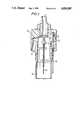
- FIG. 1is a perspective view of a steerable manipulative device.
- FIG. 2is a vertical cross section through the nozzle
- FIG. 3shows a schematic arrangement of a joystick control unit for the device.
- FIG. 4shows a schematic diagram of a hydraulic system for use with the joystick.
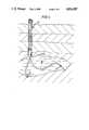
- FIG. 5shows an arrangement using a steerable nozzle unit for borehole mining.
- FIG. 6is a vertical section through a manipulative device having a single peripheral steering nozzle.
- FIG. 1shows a remotely controllable flexible nozzle which is capable of intrinsic positional feedback and self energising restoring force to counteract a disturbance from the desired position.
- the nozzlecomprises manipulative device in the form of a nozzle head (1), a flexible hose (2) and a system of operating tendons (3).
- the nozzle headhas a cutting jet nozzle and three peripheral steering jet nozzles (5), the steering jet nozzles having associated piston valves (6) and are capable of jetting fluid at right angles to the major nozzle head axis.
- the nozzle headis connected to a length of flexible line or hose (2).
- the hose (2)is fitted with guide rings (7) which locate three equally spaced stranded wire tendons (3) which are used to operate the piston valves (6) of the steering jet nozzles (5).
- the tendons (3)are linked to the remote operating source for example a joystick (9) by means of Bowden cables which terminate at a fixed reference point (4) which comprises an abutment ring having three attachment points for the Bowden cable outer tubes (8).
- An alternative inextensible hose systemcould comprise other flexible means, such as bellows or convoluted tubing of say metal or plastics material construction.
- FIG. 2shows the nozzle head in more detail.
- the nozzle headcomprises a nylon body (10) having a forwardly directed cutting nozzle (11) and three equally axially spaced steering jet nozzles (12) capable of directing fluid at right angles to the cutting jet nozzle (11).
- the headhas a co-axial plug valve (13) controlling the cutting jet nozzle (11) which is actuated by a tension wire (14) passing along the hose (18) from the supply end.
- Each steering jet nozzle (12)is operated by a piston valve (15) operated by a tendon wire (16).
- the headalso has a reaction jet (17) which i directed so as to enable advancement of the nozzle head.
- the nozzle headis connected to a flexible hose having guide ring around its periphery for locating the tendons.
- the flexible hose (18)is connected through an adaptor to a control unit in the form of a two-axis joystick assembly mechanically operating the nozzle head through the tendons (see FIG. 3).
- three jets (5) equi-spaced radially around the nozzle assemblyare modulated by piston valves (6) in the assembly to drive it to any desired position (see FIG. 1).
- the piston valves (6)are controlled by three tendons (3), the lengths of which may be varied differentially, at the fixed end of the hose (2), to define the desired position of the nozzle.
- the tendons (3)are equi-spaced around the flexible section of the hose and conform to its curvature, which may be in any plane.
- the tendonsact as automatic positional feedback since changes in curvature will be sensed as changes in "length" due to differences in radius inside and outside the bend.
- the piston valves (6)are arranged so that extension of the tendon increases the flow and thrust of the steering jet, and vice versa.
- the self-correction featuremay be illustrated by considering a tendon on the outside of the hose curve. If the curvature is less than desired the difference in lengths of the inner and outer tendons will be exaggerated by the smaller than desired difference in radii. Thus the outer tendon will appear to be extended at the nozzle head, allowing the piston valve to open, increasing the jet thrust and tending to increase the curvature, towards the desired position. As the latter is approached, the tendon will appear to "shorten” with the increase in curvature, until the nozzle comes to rest with the positioning jets in equilibrium.
- FIG. 3shows a simple joystick unit as used for this application.
- the joystick (19)is mounted on a triangular base (20) by a ball joint, allowing it to rock in two planes. Attached at the joystick midpoint are the three bowden cable inner wires (21) which lead to the three corners of the base, where the outer tubes (22) of the Bowden cables are terminated. Adjusters (23) allow for fine adjustment of the cable lengths.
- the wires (21)form a triangular pyramid, and movement of the joystick in any direction varies the length of each of the former differently to provide the necessary linear input to each tendon wire at the device.
- the nozzleis able to sweep a hemispherical area about the fixed end of the hose.
- the nozzlewill be automatically driven to the defined position, to an accuracy defined by any differential piston valve displacement required to achieve steering jet equilibrium at that position. Any force at the nozzle tending to deflect it from the desired position will be automatically detected by changes in perceived tendon length, and the intensities of the three steering jets will be adjusted to a new equilibrium resisting the disturbing force.
- the devicewill detect and feed back to the remote control joystick the existence of obstacles to it reaching the desired position. Because of the high speed of response to control inputs, the position, angle and velocity of the nozzle carrier body is proportional to the deflection and rate of movement of the joystick. If the moving end of the device encounters an immovable obstruction, it will not be possible to move the joystick further in that direction if the full steering jet control valve stroke has been taken up. With an all-mechanical Bowden cable control link, this provides an automatic tactile force feedback of obstructions to angular deflection of the nozzle.
- Reaction thrust from the cutting jetmay be opposed by fixed balancer jets.
- One arrangementwould be to arrange the latter to resist, say, 80% of thrust.
- the three steering jetsare now angled backwards, say by 30° towards the fixed end of the nose.
- the total intensity of the steering jetsmay be varied to give, say, a variation of 10% to 30% of cutting jet thrust.
- total overall balancing thrustis adjustable from 90% to 110% of cutting jet thrust, and a nozzle "forward and reverse" control is achieved.
- the steering jets (12)may be used in a direction at right angles to the cutting jet (11) and a separate jet nozzle (17) used which provides a forward thrust (see FIG. 2).
- additional flexible sections of hosemay be connected in series, each independently controlled by it own set of nozzles and tendons.
- the flexible sectionsmay be connected by rigid lengths.
- the relevant control jetsshould be situated at the outer end of the rigid section.
- the nozzlemay function as a movable suction head with the main passage connected to a jet pump or similar means.
- the devicemay be used to form a flexible manipulator arm for submersible craft, remotely operated vehicles, or robot devices both subsea and onshore.
- the cutting jet of the devicemay be replaced by fitting an end effector or gripper to the nozzle body.
- the flexible inextensible hose sectionis inflated with fluid, for example water or compressed air, to form a flexible strut to carry the nozzle body and gripper assembly.
- the position of the nozzle body and gripper, relative to the fixed endis controlled as described above with the steering jets driving the overall tube curvature to that defined by the linear extensions of the three tendons.
- Positional accuracymay be increased by replacing the piston valves shown with other valves of "dead-beat" geometry, such as poppet valves.
- the initial rate of opening of these valvesis much higher with respect to any given amount of tendon extension "error” signal. This will result in much smaller valve position and tendon extension "offsets" when the steering jets reach equilibrium, giving a smaller difference between the actual, and desired equilibrium positions.
- the valves and steering jetswill also react more rapidly to any force tending to disturb the gripper from its desired position. For instance, an object picked up by the gripper will transfer its weight to the device "arm", the steering jets automatically sensing and compensating for the new force.
- valve sensitivityAs with similar control systems, mechanical, electrical, or hydraulic, a balance between valve sensitivity and self-oscillation will limit the ultimate amount of positional precision available.
- the end effector, or grippermay be itself multi-functional, for example having "wrist rotation” in addition to grip. These functions may be controlled by mechanical or electrical or other cables passing through the bore of the flexible hose and may be powered by the pressurised working fluid contained in the hose.
- Two or more active device sectionsmay be connected in series, with separate control for each section. This will give true 6-axis rotation and translation capability to the gripper and end body.
- a typical non-submerged robotic manipulator applicationwould be as a paint-spraying "arm".
- the paint spray devicewould be mounted on the nozzle body, deriving its air supply from the "working” air inside the flexible hose, which also powers the steering jets.
- the tendon wire positionsare controlled from the remote joystick unit by incorporating them as extensions of Bowden cables.
- this controlmust be over a distance in excess of, say, 5 meters, mechanical friction in the Bowden cables will inhibit proper control.
- the Bowden cablesmay be replaced by electric, hydraulic, or pneumatic linear positioners controlled remotely from a joystick unit or software-driven control unit.
- Full positional feedback from positioner to joystickis essential.
- force feedbackis also essential due to the obstacle-detecting quality of the servo-snake control method, which would otherwise be lost.
- FIG. 4A simple, low pressure, hydraulic "umbilical” system is illustrated in FIG. 4. For simplicity, one tendon “channel” only is shown, a total of three being required to control the three tendons per device section.
- a joystick (24)is mounted on a ball-joint (25), and connected to a low pressure hydraulic cylinder (26).
- the pressure side of the pistonis connected by the umbilical line (27) which may be up to a hundred meters long, to the pressure side of the slave cylinder (29) located at the fixed (reference) end of the device.
- the slave cylinder (29)controls the length of tendon wire (30), which is under tension.
- Movement of the joystick (24)will cause its cylinder piston to move, displacing fluid, and causing the slave cylinder to follow, moving the tendon wire to a new position.
- the force needed to move the tendon wirewill be felt at the joystick.
- Both sides of the circuitare connected to reserve tank (33) via vacuum breaker valves (31) and relief valves (32).
- any mismatch of the cylinder positionsmay be reset periodically from the joystick unit without access to the remote slave cylinder location.
- the reset processoccurs as follows, (a) the joystick cylinder is moved towards its full extension position, (b) because of the positional mismatch, the slave piston will reach the end of its stroke whilst the joystick cylinder is still at 25%. This will be sensed by an increase in force required to move the joystick.
- the degree of mismatchmay be deduced from the amount of joystick deflection at this point, (c) When the slave cylinder end point is sensed, reset valve (34) is opened, allowing fluid to transfer from left to right of the joystick cylinder piston, and permitting it to reach the end of its travel. Both cylinders are now at their reference position, and (d) Normal operation is resumed by closing the reset valve (34) and returning the joystick cylinder to its working position, which will cause the slave cylinder and tendon wire to follow.
- a practical systemwill have three loops as described, one for each tendon.
- the three return sides of the loops (28)may be connected to a single line as indicated at (35). Only four hoses are thus required to provide the three independent channels of control. A total of four pairs of valves (31) and (32) are required.
- a reset processrequires that all three joystick cylinders are simultaneously moved to their reference positions. This may be done by releasing mechanical lock (36), allowing the stick itself to be slid vertically downwards through the ball joint until all three cylinders reach their full extension.
- the three reset valves (34)would be ganged together to simplify operation.
- the reset operationmay be made to occur automatically when a mismatch or relief is detected.
- the system describedprovides a low cost link between joystick and tendon wires, with minimum friction and full position and force feedback.
- FIG. 5shows a conceptual approach to borehole mining which uses carrier devices according to the present invention.
- a well bore section 37communicates with the cavern 38 and there are carrier devices having a controllable steerable spoil suction head 39 and a steerable cutting head 40.
- the cutting head 40displaces, say, minerals from the formation, the spoil being collected by the suction head 39.
- FIG. 6shows an alternative form of nozzle head having a single circumferential fluid outlet.
- the nozzle headcomprises a first cone shaped section 41 and a second cone shaped section 42, the first section 41 being capable of ⁇ floating ⁇ on the second section 42 so as to form a circumferential outlet 43.
- the particular embodiment shownalso has a cutting nozzle 45.
Landscapes
- Engineering & Computer Science (AREA)
- Robotics (AREA)
- Mining & Mineral Resources (AREA)
- Geology (AREA)
- Life Sciences & Earth Sciences (AREA)
- Mechanical Engineering (AREA)
- General Life Sciences & Earth Sciences (AREA)
- Fluid Mechanics (AREA)
- Environmental & Geological Engineering (AREA)
- Physics & Mathematics (AREA)
- Geochemistry & Mineralogy (AREA)
- Manipulator (AREA)
- Earth Drilling (AREA)
- Nozzles (AREA)
- Perforating, Stamping-Out Or Severing By Means Other Than Cutting (AREA)
- Massaging Devices (AREA)
- Undergarments, Swaddling Clothes, Handkerchiefs Or Underwear Materials (AREA)
- Drilling And Exploitation, And Mining Machines And Methods (AREA)
Abstract
Description
The present invention relates to manipulative devices capable of being remotely operated.
Manipulative devices enable operations and inspections to be carried out remotely from an operator. Thus they are useful for operating on or inspecting limited access or closed sites such as when handling hazardous materials. Also it is often desirable, for example for jet cutting in borehole mining, to use a nozzle having means which allow nozzle orientation and position to be controlled remotely. This arrangement enables the cutting nozzle to approach the target formation in a water environment closely enough to retain jet cutting efficiency without impairment by jet attenuation caused by too much water between the nozzle and formation.
According to the present invention there is provided a manipulative device capable of remote operation comprising a nozzle head having one or more nozzles adapted to eject a fluid stream having a component at right angles to the axis of the nozzle head, the nozzle head being connectable by a flexible elongate member to a reference point, a means for controlling fluid flow through the nozzles, the means being capable of operation by tendons adapted to follow the curvature of the flexible elongate member whereby, in use, remote differential operation of the tendons enables spatial positioning of the nozzle head.
In one embodiment of the invention, the device is in the form of a cutting nozzle head which has a forwardly directed cutting nozzle capable of controllably jetting fluid. The fluid may be, for example, air or water. The device has a plurality of steering nozzles (preferably three) in the periphery which are capable of jetting fluid outwardly at right angles to the cutting nozzle. The fluid flow through the steering nozzles is controlled preferably by valves, the valves being remotely operable by means of tendons or control wires. The device may have a further nozzle capable of jetting fluid having a backward component of flow so as to provide a forward thrust to the carrier device. Alternatively the device may be moved by separate translational means such as mechanical operation. The device is connected to the source of remote operation by for example, a flexible inextensible hose. The tendons or control wires may be located by rings or tubes on the periphery of the hose and the tendon or control wire lengths are capable of differential variation by means of, for example, a joystick system so as to position the cutting nozzle at a desired location. This arrangement may be used, for example, to controllably hold a cutting jet against the face of a borehole.
The device may be used in various environments such as air, liquids e.g. water and slurries.
The invention will now be described by way of example only and with reference to the accompanying drawings.
FIG. 1 is a perspective view of a steerable manipulative device.
FIG. 2 is a vertical cross section through the nozzle
FIG. 3 shows a schematic arrangement of a joystick control unit for the device.
FIG. 4 shows a schematic diagram of a hydraulic system for use with the joystick.
FIG. 5 shows an arrangement using a steerable nozzle unit for borehole mining.
FIG. 6 is a vertical section through a manipulative device having a single peripheral steering nozzle.
Economic borehole mining requires that the cutting nozzle can approach close to the target formation so that attenuation of the cutting jet by the surrounding fluid is reduced. FIG. 1 shows a remotely controllable flexible nozzle which is capable of intrinsic positional feedback and self energising restoring force to counteract a disturbance from the desired position. The nozzle comprises manipulative device in the form of a nozzle head (1), a flexible hose (2) and a system of operating tendons (3). The nozzle head has a cutting jet nozzle and three peripheral steering jet nozzles (5), the steering jet nozzles having associated piston valves (6) and are capable of jetting fluid at right angles to the major nozzle head axis. The nozzle head is connected to a length of flexible line or hose (2). The hose (2) is fitted with guide rings (7) which locate three equally spaced stranded wire tendons (3) which are used to operate the piston valves (6) of the steering jet nozzles (5). The tendons (3) are linked to the remote operating source for example a joystick (9) by means of Bowden cables which terminate at a fixed reference point (4) which comprises an abutment ring having three attachment points for the Bowden cable outer tubes (8).
An alternative inextensible hose system could comprise other flexible means, such as bellows or convoluted tubing of say metal or plastics material construction.
FIG. 2 shows the nozzle head in more detail. The nozzle head comprises a nylon body (10) having a forwardly directed cutting nozzle (11) and three equally axially spaced steering jet nozzles (12) capable of directing fluid at right angles to the cutting jet nozzle (11). The head has a co-axial plug valve (13) controlling the cutting jet nozzle (11) which is actuated by a tension wire (14) passing along the hose (18) from the supply end. Each steering jet nozzle (12) is operated by a piston valve (15) operated by a tendon wire (16). The head also has a reaction jet (17) which i directed so as to enable advancement of the nozzle head. The nozzle head is connected to a flexible hose having guide ring around its periphery for locating the tendons. The flexible hose (18) is connected through an adaptor to a control unit in the form of a two-axis joystick assembly mechanically operating the nozzle head through the tendons (see FIG. 3).
During use, three jets (5) equi-spaced radially around the nozzle assembly are modulated by piston valves (6) in the assembly to drive it to any desired position (see FIG. 1). The piston valves (6) are controlled by three tendons (3), the lengths of which may be varied differentially, at the fixed end of the hose (2), to define the desired position of the nozzle. The tendons (3) are equi-spaced around the flexible section of the hose and conform to its curvature, which may be in any plane. The tendons act as automatic positional feedback since changes in curvature will be sensed as changes in "length" due to differences in radius inside and outside the bend.
The piston valves (6) are arranged so that extension of the tendon increases the flow and thrust of the steering jet, and vice versa. The self-correction feature may be illustrated by considering a tendon on the outside of the hose curve. If the curvature is less than desired the difference in lengths of the inner and outer tendons will be exaggerated by the smaller than desired difference in radii. Thus the outer tendon will appear to be extended at the nozzle head, allowing the piston valve to open, increasing the jet thrust and tending to increase the curvature, towards the desired position. As the latter is approached, the tendon will appear to "shorten" with the increase in curvature, until the nozzle comes to rest with the positioning jets in equilibrium.
Since the tendons are only controlling the piston valves, forces are low and approximately constant, the fluid pressure on the end of the piston valve providing a steady tensile force to overcome tendon friction and balance tension. A light spring is also fitted to allow the valves to follow tendon movement under low pressure "start-up" conditions.
The device is thus controlled by the tendon positions which may be mechanically linked to a simple joystick arrangement (9), or to automatic control devices. FIG. 3 shows a simple joystick unit as used for this application. The joystick (19) is mounted on a triangular base (20) by a ball joint, allowing it to rock in two planes. Attached at the joystick midpoint are the three bowden cable inner wires (21) which lead to the three corners of the base, where the outer tubes (22) of the Bowden cables are terminated. Adjusters (23) allow for fine adjustment of the cable lengths. The wires (21) form a triangular pyramid, and movement of the joystick in any direction varies the length of each of the former differently to provide the necessary linear input to each tendon wire at the device. The nozzle is able to sweep a hemispherical area about the fixed end of the hose. The nozzle will be automatically driven to the defined position, to an accuracy defined by any differential piston valve displacement required to achieve steering jet equilibrium at that position. Any force at the nozzle tending to deflect it from the desired position will be automatically detected by changes in perceived tendon length, and the intensities of the three steering jets will be adjusted to a new equilibrium resisting the disturbing force.
The device will detect and feed back to the remote control joystick the existence of obstacles to it reaching the desired position. Because of the high speed of response to control inputs, the position, angle and velocity of the nozzle carrier body is proportional to the deflection and rate of movement of the joystick. If the moving end of the device encounters an immovable obstruction, it will not be possible to move the joystick further in that direction if the full steering jet control valve stroke has been taken up. With an all-mechanical Bowden cable control link, this provides an automatic tactile force feedback of obstructions to angular deflection of the nozzle.
Reaction thrust from the cutting jet may be opposed by fixed balancer jets. One arrangement would be to arrange the latter to resist, say, 80% of thrust. The three steering jets are now angled backwards, say by 30° towards the fixed end of the nose. By collective movement of all three tendons, the total intensity of the steering jets may be varied to give, say, a variation of 10% to 30% of cutting jet thrust. Thus total overall balancing thrust is adjustable from 90% to 110% of cutting jet thrust, and a nozzle "forward and reverse" control is achieved. Alternatively the steering jets (12) may be used in a direction at right angles to the cutting jet (11) and a separate jet nozzle (17) used which provides a forward thrust (see FIG. 2).
In order to economically mine extensive caverns, additional flexible sections of hose may be connected in series, each independently controlled by it own set of nozzles and tendons. If desired, the flexible sections may be connected by rigid lengths. In this case, the relevant control jets should be situated at the outer end of the rigid section.
If a separate steering jet supply is provided, such as by a coaxial hose, the nozzle may function as a movable suction head with the main passage connected to a jet pump or similar means.
Further possible modes of use of the device are described below.
The device may be used to form a flexible manipulator arm for submersible craft, remotely operated vehicles, or robot devices both subsea and onshore.
In one embodiment, the cutting jet of the device may be replaced by fitting an end effector or gripper to the nozzle body. The flexible inextensible hose section is inflated with fluid, for example water or compressed air, to form a flexible strut to carry the nozzle body and gripper assembly. The position of the nozzle body and gripper, relative to the fixed end is controlled as described above with the steering jets driving the overall tube curvature to that defined by the linear extensions of the three tendons.
Positional accuracy may be increased by replacing the piston valves shown with other valves of "dead-beat" geometry, such as poppet valves. The initial rate of opening of these valves is much higher with respect to any given amount of tendon extension "error" signal. This will result in much smaller valve position and tendon extension "offsets" when the steering jets reach equilibrium, giving a smaller difference between the actual, and desired equilibrium positions. The valves and steering jets will also react more rapidly to any force tending to disturb the gripper from its desired position. For instance, an object picked up by the gripper will transfer its weight to the device "arm", the steering jets automatically sensing and compensating for the new force.
As with similar control systems, mechanical, electrical, or hydraulic, a balance between valve sensitivity and self-oscillation will limit the ultimate amount of positional precision available.
The end effector, or gripper, may be itself multi-functional, for example having "wrist rotation" in addition to grip. These functions may be controlled by mechanical or electrical or other cables passing through the bore of the flexible hose and may be powered by the pressurised working fluid contained in the hose.
Two or more active device sections may be connected in series, with separate control for each section. This will give true 6-axis rotation and translation capability to the gripper and end body.
A typical non-submerged robotic manipulator application would be as a paint-spraying "arm". The paint spray device would be mounted on the nozzle body, deriving its air supply from the "working" air inside the flexible hose, which also powers the steering jets.
In the embodiments described above, the tendon wire positions are controlled from the remote joystick unit by incorporating them as extensions of Bowden cables. For embodiments where this control must be over a distance in excess of, say, 5 meters, mechanical friction in the Bowden cables will inhibit proper control. In this case, the Bowden cables may be replaced by electric, hydraulic, or pneumatic linear positioners controlled remotely from a joystick unit or software-driven control unit. Full positional feedback from positioner to joystick is essential. Ideally, force feedback is also essential due to the obstacle-detecting quality of the servo-snake control method, which would otherwise be lost.
A simple, low pressure, hydraulic "umbilical" system is illustrated in FIG. 4. For simplicity, one tendon "channel" only is shown, a total of three being required to control the three tendons per device section. A joystick (24) is mounted on a ball-joint (25), and connected to a low pressure hydraulic cylinder (26). The pressure side of the piston is connected by the umbilical line (27) which may be up to a hundred meters long, to the pressure side of the slave cylinder (29) located at the fixed (reference) end of the device. The slave cylinder (29) controls the length of tendon wire (30), which is under tension.
The other sides of the joystick and slave cylinder pistons are connected by the common return line (28) to complete the hydraulic circuit.
Movement of the joystick (24) will cause its cylinder piston to move, displacing fluid, and causing the slave cylinder to follow, moving the tendon wire to a new position. The force needed to move the tendon wire will be felt at the joystick.
Since the fluid in the signal side of the circuit (27) should always be pressurised by the tendon wire tension, any leakage in the cylinders will cause the slave cylinder piston to move downwards, losing its relationship to the position of that in the joystick cylinder. If the umbilical pipes (27) and (28) are of significant length, thermal expansion or contraction of the fluid or pipes may also upset the relationship.
Both sides of the circuit are connected to reserve tank (33) via vacuum breaker valves (31) and relief valves (32).
Any mismatch of the cylinder positions may be reset periodically from the joystick unit without access to the remote slave cylinder location. Assuming that the slave piston is displaced downwards to, say, the 25% travel position, the reset process occurs as follows, (a) the joystick cylinder is moved towards its full extension position, (b) because of the positional mismatch, the slave piston will reach the end of its stroke whilst the joystick cylinder is still at 25%. This will be sensed by an increase in force required to move the joystick. For diagnostic purposes, the degree of mismatch may be deduced from the amount of joystick deflection at this point, (c) When the slave cylinder end point is sensed, reset valve (34) is opened, allowing fluid to transfer from left to right of the joystick cylinder piston, and permitting it to reach the end of its travel. Both cylinders are now at their reference position, and (d) Normal operation is resumed by closing the reset valve (34) and returning the joystick cylinder to its working position, which will cause the slave cylinder and tendon wire to follow.
During normal and reset operations any loss of fluid from the control loop will be made up from the reserve tank via the vacuum breaker valves.
Normal system pressure would be below 10 bar but excessive force on the joystick, or abnormal loading on the tendon wire might exceed this. Overpressure in either line is protected against by the relief valves (32), which return fluid to the reserve tank. Since loss of fluid by relief from either side of the control loop will cause a mismatch, opening of a relief valve will be made to cause an indication at the joystick unit that a reset operation is necessary.
A practical system will have three loops as described, one for each tendon. For reasons of cost, simplicity, etc, the three return sides of the loops (28) may be connected to a single line as indicated at (35). Only four hoses are thus required to provide the three independent channels of control. A total of four pairs of valves (31) and (32) are required.
During normal operation, the three joystick cylinder extensions change independently to transmit the three position signals to the tendons. A reset process requires that all three joystick cylinders are simultaneously moved to their reference positions. This may be done by releasing mechanical lock (36), allowing the stick itself to be slid vertically downwards through the ball joint until all three cylinders reach their full extension. The three reset valves (34) would be ganged together to simplify operation.
If the vertical length of the stick lower half is controlled by a mechanical device such as a pneumatic cylinder, the reset operation may be made to occur automatically when a mismatch or relief is detected.
The system described provides a low cost link between joystick and tendon wires, with minimum friction and full position and force feedback.
FIG. 5 shows a conceptual approach to borehole mining which uses carrier devices according to the present invention. Awell bore section 37 communicates with thecavern 38 and there are carrier devices having a controllable steerablespoil suction head 39 and asteerable cutting head 40. The cuttinghead 40 displaces, say, minerals from the formation, the spoil being collected by thesuction head 39.
FIG. 6 shows an alternative form of nozzle head having a single circumferential fluid outlet. The nozzle head comprises a first cone shapedsection 41 and a second cone shaped section 42, thefirst section 41 being capable of `floating` on the second section 42 so as to form acircumferential outlet 43. Displacement of the first floating section relative to the fixed second section by the tendon 44 (one of three tendons arranged around the hose) passing through guide rings 46 on thehose 47 given an asymmetric configuration to the fluid jet giving rise to the spatial displacement of the nozzle head. The particular embodiment shown also has a cuttingnozzle 45.
Claims (13)
1. A manipulative device capable of remote operation comprising in combination:
a nozzle head having an axis and one or more nozzles adapted to eject a fluid stream having a component at right angles to said axis,
a flexible elongate member connecting said nozzle head to a reference point, said nozzle having means for controlling said fluid streams through said nozzles, tendons operably connected to said fluid control means, said tendons being adapted to follow the curvature of said flexible elongate member so as to impart feedback of said nozzle head position,
whereby in use, remote differential operation of said tendons enables spatial positioning of said nozzle head, by said one or more fluid streams.
2. A manipulative device according to claim 1 having a plurality of equally spaced nozzles.
3. A manipulative device according to claim 1 having a single circumferential nozzle.
4. A manipulative device according to claim 3 in which the single circumferential nozzle comprises a first cone shaped section and a second cone shaped section, the first section being capable of floating on the second section to form a circumferential fluid outlet.
5. A manipulative device according to claim 1 in which the nozzle or nozzles have a component of velocity enabling translational movement of the nozzle head.
6. A manipulative device according to claim 1 having separate means for translational movement.
7. A manipulative device according to claim 1 in which the flexible elongate member is a flexible inextensible hose, a system of bellows or convoluted tubing.
8. A manipulative device according to claim 7 in which the tendons are located by guide rings or a tube on the periphery of the flexible inextensible hose.
9. A manipulative device according to claim 7 in which the flexible elongate member comprises a plurality of flexible sections, each of which is capable of separate control by nozzles and tendons.
10. A manipulative device according to claim 1 having means for remote operation of the tendons comprising a joystick system.
11. A manipulative device according to claim 1 having means for remote operation comprising electric, hydraulic or pneumatic linear positioners controllable remotely from a joystick unit or a software driven control unit.
12. A manipulative device according to claim 1 in which the fluid controlling means are valves.
13. A manipulative device according to claim 1 having a cutting nozzle.
Applications Claiming Priority (2)
| Application Number | Priority Date | Filing Date | Title |
|---|---|---|---|
| GB8503547 | 1985-02-12 | ||
| GB858503547AGB8503547D0 (en) | 1985-02-12 | 1985-02-12 | Nozzle |
Publications (1)
| Publication Number | Publication Date |
|---|---|
| US4826087Atrue US4826087A (en) | 1989-05-02 |
Family
ID=10574329
Family Applications (1)
| Application Number | Title | Priority Date | Filing Date |
|---|---|---|---|
| US06/919,251Expired - Fee RelatedUS4826087A (en) | 1985-02-12 | 1986-02-06 | Manipulative device |
Country Status (14)
| Country | Link |
|---|---|
| US (1) | US4826087A (en) |
| EP (1) | EP0194039B1 (en) |
| JP (1) | JPS62501861A (en) |
| KR (1) | KR870700037A (en) |
| CN (1) | CN1003918B (en) |
| AU (1) | AU579006B2 (en) |
| BR (1) | BR8605547A (en) |
| CA (1) | CA1267178A (en) |
| DE (1) | DE3663903D1 (en) |
| GB (1) | GB8503547D0 (en) |
| IN (1) | IN166893B (en) |
| MY (1) | MY100487A (en) |
| WO (1) | WO1986004537A1 (en) |
| ZA (1) | ZA86898B (en) |
Cited By (102)
| Publication number | Priority date | Publication date | Assignee | Title |
|---|---|---|---|---|
| US4923021A (en)* | 1988-12-30 | 1990-05-08 | Conoco Inc. | Combination bit for coking oven |
| US5065703A (en)* | 1987-03-18 | 1991-11-19 | Electric Power Research Institute, Inc. | Flexible lance for steam generator secondary side sludge removal |
| US5194217A (en)* | 1992-01-10 | 1993-03-16 | The Babcock & Wilcox Company | Articulated sludge lance with a movable extension nozzle |
| WO1993008867A3 (en)* | 1991-11-05 | 1993-06-24 | Naomi L Nakao | Apparatus for laparoscopic and endoscopic surgery |
| US5269464A (en)* | 1992-02-06 | 1993-12-14 | Mercedes-Benz Ag | Spraying device for motor vehicle headlamp-cleaning systems |
| US5273535A (en)* | 1991-11-08 | 1993-12-28 | Ep Technologies, Inc. | Catheter with electrode tip having asymmetric left and right curve configurations |
| US5279559A (en)* | 1992-03-06 | 1994-01-18 | Aai Corporation | Remote steering system for medical catheter |
| US5318525A (en)* | 1992-04-10 | 1994-06-07 | Medtronic Cardiorhythm | Steerable electrode catheter |
| US5334207A (en)* | 1993-03-25 | 1994-08-02 | Allen E. Coles | Laser angioplasty device with magnetic direction control |
| US5358478A (en)* | 1990-02-02 | 1994-10-25 | Ep Technologies, Inc. | Catheter steering assembly providing asymmetric left and right curve configurations |
| US5363882A (en)* | 1989-10-13 | 1994-11-15 | Kabushiki Kaisha Machida Seisakusho | Bending device having a bellows |
| US5383852A (en)* | 1992-12-04 | 1995-01-24 | C. R. Bard, Inc. | Catheter with independent proximal and distal control |
| US5395327A (en)* | 1990-02-02 | 1995-03-07 | Ep Technologies, Inc. | Catheter steering mechanism |
| US5397304A (en)* | 1992-04-10 | 1995-03-14 | Medtronic Cardiorhythm | Shapable handle for steerable electrode catheter |
| US5462527A (en)* | 1993-06-29 | 1995-10-31 | C.R. Bard, Inc. | Actuator for use with steerable catheter |
| US5498239A (en)* | 1995-04-17 | 1996-03-12 | Guided Medical Systems, Inc. | Catheter placement by pressurizable tubular guiding core |
| US5520644A (en)* | 1991-11-18 | 1996-05-28 | Intelliwire, Inc. | Flexible elongate device having steerable distal extremity and apparatus for use therewith and method |
| US5715817A (en)* | 1993-06-29 | 1998-02-10 | C.R. Bard, Inc. | Bidirectional steering catheter |
| US5779699A (en)* | 1996-03-29 | 1998-07-14 | Medtronic, Inc. | Slip resistant field focusing ablation catheter electrode |
| US5879057A (en) | 1996-11-12 | 1999-03-09 | Amvest Corporation | Horizontal remote mining system, and method |
| US5891088A (en)* | 1990-02-02 | 1999-04-06 | Ep Technologies, Inc. | Catheter steering assembly providing asymmetric left and right curve configurations |
| US6026701A (en)* | 1995-11-21 | 2000-02-22 | Onera (Office National D'etudes Et De Recherches Aerospatiales | "Master-slave" remote manipulation apparatus having six degrees of freedom |
| US6033378A (en)* | 1990-02-02 | 2000-03-07 | Ep Technologies, Inc. | Catheter steering mechanism |
| US6045530A (en)* | 1998-10-14 | 2000-04-04 | Heyer-Schulte Neurocare Inc. | Adjustable angle catheter |
| US6048329A (en)* | 1996-12-19 | 2000-04-11 | Ep Technologies, Inc. | Catheter distal assembly with pull wires |
| US6066125A (en)* | 1997-09-05 | 2000-05-23 | Cordis Webster, Inc. | Omni-directional steerable catheter |
| US6071279A (en)* | 1996-12-19 | 2000-06-06 | Ep Technologies, Inc. | Branched structures for supporting multiple electrode elements |
| US6071274A (en)* | 1996-12-19 | 2000-06-06 | Ep Technologies, Inc. | Loop structures for supporting multiple electrode elements |
| US6126649A (en)* | 1999-06-10 | 2000-10-03 | Transvascular, Inc. | Steerable catheter with external guidewire as catheter tip deflector |
| US6171277B1 (en) | 1997-12-01 | 2001-01-09 | Cordis Webster, Inc. | Bi-directional control handle for steerable catheter |
| US6183463B1 (en) | 1997-12-01 | 2001-02-06 | Cordis Webster, Inc. | Bidirectional steerable cathether with bidirectional control handle |
| US6198974B1 (en) | 1998-08-14 | 2001-03-06 | Cordis Webster, Inc. | Bi-directional steerable catheter |
| US6203525B1 (en)* | 1996-12-19 | 2001-03-20 | Ep Technologies, Inc. | Catheterdistal assembly with pull wires |
| US6210407B1 (en) | 1998-12-03 | 2001-04-03 | Cordis Webster, Inc. | Bi-directional electrode catheter |
| US6217528B1 (en) | 1999-02-11 | 2001-04-17 | Scimed Life Systems, Inc. | Loop structure having improved tissue contact capability |
| US6263984B1 (en)* | 1999-02-18 | 2001-07-24 | William G. Buckman, Sr. | Method and apparatus for jet drilling drainholes from wells |
| US6332880B1 (en) | 1996-12-19 | 2001-12-25 | Ep Technologies, Inc. | Loop structures for supporting multiple electrode elements |
| US20020112598A1 (en)* | 2000-03-03 | 2002-08-22 | Miller Paul L. | Remote hazardous devices interdiction process and apparatus |
| US6464700B1 (en) | 1994-10-07 | 2002-10-15 | Scimed Life Systems, Inc. | Loop structures for positioning a diagnostic or therapeutic element on the epicardium or other organ surface |
| US6470978B2 (en) | 1995-12-08 | 2002-10-29 | University Of Queensland | Fluid drilling system with drill string and retro jets |
| US6529756B1 (en) | 1999-11-22 | 2003-03-04 | Scimed Life Systems, Inc. | Apparatus for mapping and coagulating soft tissue in or around body orifices |
| US6542781B1 (en) | 1999-11-22 | 2003-04-01 | Scimed Life Systems, Inc. | Loop structures for supporting diagnostic and therapeutic elements in contact with body tissue |
| US6571131B1 (en) | 2000-11-10 | 2003-05-27 | Biosense Webster, Inc. | Deflectable catheter with modifiable handle |
| US20030107021A1 (en)* | 2001-11-16 | 2003-06-12 | Saurwein Albert C. | Normally closed on-off valve for ultra-high-pressure applications |
| US6610055B1 (en) | 1997-10-10 | 2003-08-26 | Scimed Life Systems, Inc. | Surgical method for positioning a diagnostic or therapeutic element on the epicardium or other organ surface |
| US6613046B1 (en) | 1999-11-22 | 2003-09-02 | Scimed Life Systems, Inc. | Loop structures for supporting diagnostic and therapeutic elements in contact with body tissue |
| US6645199B1 (en) | 1999-11-22 | 2003-11-11 | Scimed Life Systems, Inc. | Loop structures for supporting diagnostic and therapeutic elements contact with body tissue and expandable push devices for use with same |
| WO2003103466A1 (en)* | 2002-06-11 | 2003-12-18 | Menashe Shamir | Bimodal flexible-rigid hose |
| US20040132383A1 (en)* | 2002-08-14 | 2004-07-08 | Langford Mark A. | Fluid jet cutting system |
| EP1496195A1 (en) | 2003-07-10 | 2005-01-12 | Gebrüder Dorfner GmbH & Co. Kaolin- und Kristallquarzsandwerke KG | Process for obtaining raw materials containing clay minerals |
| US20050015083A1 (en)* | 1994-10-07 | 2005-01-20 | Scimed Life Systems, Inc. | Loop structures for positioning a diagnostic or therapeutic element on the epicardium or other organ surface |
| US20050034901A1 (en)* | 2001-11-14 | 2005-02-17 | Meyer Timothy Gregory Hamilton | Fluid drilling head |
| US20050067166A1 (en)* | 1997-06-06 | 2005-03-31 | University Of Queensland, Commonwealth | Erectable arm assembly for use in boreholes |
| US6916306B1 (en) | 2000-11-10 | 2005-07-12 | Boston Scientific Scimed, Inc. | Steerable loop structures for supporting diagnostic and therapeutic elements in contact with body tissue |
| WO2006012421A2 (en) | 2004-07-20 | 2006-02-02 | St. Jude Medical, Atrial Fibrillation Division, Inc. | Steerable catheter with hydraulic or pneumatic actuator |
| EP1714743A1 (en)* | 2005-04-22 | 2006-10-25 | SLF Oberflächentechnik GmbH | Device for treating the inner surface of pipes |
| US20070010800A1 (en)* | 2005-06-22 | 2007-01-11 | Barry Weitzner | Medical device control system |
| US7195082B2 (en) | 2002-10-18 | 2007-03-27 | Scott Christopher Adam | Drill head steering |
| WO2007065276A1 (en)* | 2005-12-06 | 2007-06-14 | Leonam Lincoln Baptista | Flexible arm with controlled flexing |
| US20080009745A1 (en)* | 2006-04-04 | 2008-01-10 | Volcano Corporation | Ultrasound catheter and hand-held device for manipulating a transducer on the catheter's distal end |
| US20080103452A1 (en)* | 2006-10-25 | 2008-05-01 | James Walden Voegele | Adhesive applier with articulating tip |
| US20080172037A1 (en)* | 2006-11-01 | 2008-07-17 | Percutaneous Systems, Inc. | Catheter with adjustable column stability and methods for its use |
| US20080188871A1 (en)* | 2006-12-01 | 2008-08-07 | Smith Paul J | Direct drive methods |
| US20080287862A1 (en)* | 2007-05-18 | 2008-11-20 | Boston Scientific Scimed, Inc. | Drive systems and methods of use |
| CN100467881C (en)* | 2003-07-14 | 2009-03-11 | 浙江工业大学 | Pneumatic flexible ball-joint |
| US20090283649A1 (en)* | 2003-07-31 | 2009-11-19 | Wood Jeffrey H | Utility Brackets for Securing Components to Structures |
| WO2010041216A1 (en)* | 2008-10-09 | 2010-04-15 | Gardia Medical Ltd. | Apparatus and method for anchoring an elongated object in body lumens |
| US20100132938A1 (en)* | 2005-04-27 | 2010-06-03 | Frank's Casing Crew And Rental Tools, Inc. | Conductor pipe string deflector and method of using same |
| CN103075180A (en)* | 2013-01-15 | 2013-05-01 | 中国矿业大学 | Gas-liquid two-phase jet slotting system and method |
| WO2013116632A1 (en)* | 2012-02-02 | 2013-08-08 | United States Of America, As Represented By The Administrator Of The National Aeronautics And Space Administration | Tension stiffened and tendon actuated manipulator and a hinge for use therein |
| US20130237760A1 (en)* | 1999-03-12 | 2013-09-12 | Boston Scientific Scimed, Inc. | Controllable endoscopic sheath apparatus and related method of use |
| US20140360308A1 (en)* | 2013-06-10 | 2014-12-11 | Donal Walker Lumsden | Mechanical maneuvering system |
| US20150352728A1 (en)* | 2013-01-07 | 2015-12-10 | Wen Wang | Bendable, telescopic, and flexible continuum mechanical structure |
| US20150359416A1 (en)* | 2013-01-21 | 2015-12-17 | G.I. View Ltd. | Integrated steering device |
| US20160059384A1 (en)* | 2014-08-27 | 2016-03-03 | Flow International Corporation | End effector adjustment systems and methods |
| US9314593B2 (en) | 2012-09-24 | 2016-04-19 | Cook Medical Technologies Llc | Medical devices for the identification and treatment of bodily passages |
| US9375138B2 (en) | 2011-11-25 | 2016-06-28 | Cook Medical Technologies Llc | Steerable guide member and catheter |
| US9549748B2 (en) | 2013-08-01 | 2017-01-24 | Cook Medical Technologies Llc | Methods of locating and treating tissue in a wall defining a bodily passage |
| CN107433611A (en)* | 2017-08-08 | 2017-12-05 | 成都普崔克机电有限公司 | A kind of soft drive unit of energy pre-storage |
| US9833130B2 (en) | 2011-07-22 | 2017-12-05 | Cook Medical Technologies Llc | Irrigation devices adapted to be used with a light source for the identification and treatment of bodily passages |
| US9895055B2 (en) | 2013-02-28 | 2018-02-20 | Cook Medical Technologies Llc | Medical devices, systems, and methods for the visualization and treatment of bodily passages |
| US9937323B2 (en) | 2014-02-28 | 2018-04-10 | Cook Medical Technologies Llc | Deflectable catheters, systems, and methods for the visualization and treatment of bodily passages |
| US10195398B2 (en) | 2014-08-13 | 2019-02-05 | Cook Medical Technologies Llc | Tension member seal and securing mechanism for medical devices |
| US10569415B2 (en) | 2016-08-31 | 2020-02-25 | United States Of America As Represented By The Administrator Of Nasa | Tension stiffened and tendon actuated manipulator |
| US10646104B1 (en) | 2018-10-29 | 2020-05-12 | G.I. View Ltd. | Disposable endoscope |
| WO2020204837A3 (en)* | 2019-04-04 | 2020-11-05 | Kisodo Pte. Ltd. | Device, peripheral device, system and method for mining |
| US10828788B2 (en)* | 2015-07-13 | 2020-11-10 | President And Fellows Of Harvard College | Distributed pressurization and exhaust systems for soft robots |
| US20220010626A1 (en)* | 2018-11-16 | 2022-01-13 | PTRM Pty Ltd | Mining method |
| US11559191B2 (en) | 2018-10-29 | 2023-01-24 | G.I. View Ltd. | Insertion unit for medical instruments and an intubation system thereof |
| US11613003B2 (en) | 2020-01-24 | 2023-03-28 | General Electric Company | Line assembly for an extension tool having a plurality of links |
| US11654547B2 (en) | 2021-03-31 | 2023-05-23 | General Electric Company | Extension tool |
| US11692650B2 (en) | 2020-01-23 | 2023-07-04 | General Electric Company | Selectively flexible extension tool |
| US11702955B2 (en) | 2019-01-14 | 2023-07-18 | General Electric Company | Component repair system and method |
| US11707819B2 (en) | 2018-10-15 | 2023-07-25 | General Electric Company | Selectively flexible extension tool |
| US11752622B2 (en) | 2020-01-23 | 2023-09-12 | General Electric Company | Extension tool having a plurality of links |
| US11834990B2 (en) | 2020-03-10 | 2023-12-05 | Oliver Crispin Robotics Limited | Insertion tool |
| US20240173850A1 (en)* | 2022-11-26 | 2024-05-30 | Signetron Inc. | Robotic payload for extracting and depositing lightweight materials |
| US12091981B2 (en) | 2020-06-11 | 2024-09-17 | General Electric Company | Insertion tool and method |
| US12194620B2 (en) | 2018-10-15 | 2025-01-14 | Oliver Crisipin Robotics Limited | Selectively flexible extension tool |
| US12318801B2 (en) | 2022-11-14 | 2025-06-03 | General Electric Company | Force-balancing spray nozzle devices |
| US12405187B2 (en) | 2019-10-04 | 2025-09-02 | General Electric Company | Insertion apparatus for use with rotary machines |
| US12416800B2 (en) | 2021-01-08 | 2025-09-16 | General Electric Company | Insertion tool |
Families Citing this family (22)
| Publication number | Priority date | Publication date | Assignee | Title |
|---|---|---|---|---|
| FR2587644B1 (en)* | 1985-09-24 | 1987-12-24 | Lorin De La Grandmaison Didier | DEVICE FOR CONNECTING TWO OBJECTS AND VARYING THEIR RELATED POSITION AND ORIENTATION APPLICABLE IN PARTICULAR TO MANIPULATOR ARMS |
| DE4214378C1 (en)* | 1992-04-30 | 1993-08-26 | Siemens Ag, 8000 Muenchen, De | |
| SE503140C2 (en)* | 1992-05-07 | 1996-04-01 | Dart Engineering Ag | Device at media transmitting unit |
| FR2729881A1 (en)* | 1995-01-31 | 1996-08-02 | Commissariat Energie Atomique | Apparatus for controlling the movement of inspection/intervention apparatus in a hostile medium |
| RU2011102169A (en)* | 2008-06-27 | 2012-08-10 | Эллидженс Корпарейшен (Us) | FLEXIBLE Wrist ELEMENT, METHODS FOR ITS MANUFACTURE AND USE |
| WO2012026489A1 (en)* | 2010-08-25 | 2012-03-01 | いずみテクノス株式会社 | Device for painting inner surface of existing pipe |
| DE102011108262B4 (en)* | 2011-07-25 | 2015-12-17 | Eisenmann Ag | Apparatus for painting vehicle bodies with a plurality of gestaltveranderlichen arms |
| CN102817360B (en)* | 2012-08-21 | 2015-04-08 | 中国葛洲坝集团国际工程有限公司 | Concrete spraying construction device and method |
| CN102990676A (en)* | 2012-11-23 | 2013-03-27 | 中国航空工业集团公司北京航空制造工程研究所 | Snakelike mechanical arm |
| CN108756749A (en)* | 2013-07-25 | 2018-11-06 | 哈里伯顿能源服务公司 | Method for making outer circle angular component deflect |
| CN103831840A (en)* | 2014-03-31 | 2014-06-04 | 东南大学 | Lasso-drive-based search mechanism for robot |
| CN104690725B (en)* | 2015-01-06 | 2016-04-27 | 泰华宏业(天津)机器人技术研究院有限责任公司 | The attitude control method of snake-shaped robot |
| CN106271870A (en)* | 2016-10-15 | 2017-01-04 | 山东大学 | A kind of flexible joint nozzle |
| FR3073812B1 (en)* | 2017-11-20 | 2021-05-14 | Panipa | DEVICE FOR PUMPING WATER TO A GREAT DEPTH |
| CN108825540A (en)* | 2018-08-16 | 2018-11-16 | 郑州云海信息技术有限公司 | A kind of fan of variable wind direction |
| GB2563550B (en)* | 2018-09-27 | 2019-08-28 | Arnautov Maksim | A mining machine |
| CN109466403B (en)* | 2018-10-13 | 2020-11-20 | 广东嗨学云教育科技有限公司 | Earthquake rescue robot capable of conveniently carrying materials |
| CN111790703B (en)* | 2020-06-30 | 2022-03-25 | 中国石油大学(北京) | Cleaning tool and cleaning method for insoluble substances at bottom of salt cavern gas storage cavity |
| CN112847841B (en)* | 2021-01-14 | 2022-12-09 | 中铁工程装备集团有限公司 | Stone treatment robot for tunnel boring machine and tunnel boring machine |
| CN116019082B (en)* | 2023-03-14 | 2024-09-13 | 宁夏大学 | Be applied to high-efficient management equipment that fruit tree planted |
| CN118218168B (en)* | 2024-05-27 | 2024-09-10 | 山东鲁源消防科技有限公司 | Plastic-coated device in heavy-calibre slot pipe fitting |
| CN119043856B (en)* | 2024-11-01 | 2025-05-13 | 南通市恒瑞精密机械制造有限公司 | A classification mechanism for detecting irregular hardware surface defects |
Citations (20)
| Publication number | Priority date | Publication date | Assignee | Title |
|---|---|---|---|---|
| US671429A (en)* | 1898-06-14 | 1901-04-09 | Bacon Air Lift Company | Process of making or improving wells. |
| US1232489A (en)* | 1916-08-28 | 1917-07-10 | Charles H Field | Sprayer. |
| US2251916A (en)* | 1939-06-12 | 1941-08-12 | Cross Roy | Water mining soluble materials |
| US2498692A (en)* | 1949-01-04 | 1950-02-28 | Mains Marshall Paul | Gastrointestinal tube |
| US2696262A (en)* | 1951-11-17 | 1954-12-07 | Walter D Powers | Apparatus for removing loose sand or the like from well bores |
| US2698665A (en)* | 1951-12-22 | 1955-01-04 | Rockwood Sprinkler Co | Control apparatus for fire-fighting turrets |
| US2873092A (en)* | 1957-11-14 | 1959-02-10 | Roy P Dwyer | Jet deflection method of deviating a bore hole |
| US3058473A (en)* | 1959-11-27 | 1962-10-16 | Alfred E Whitchead | Remotely directing catheters and tools |
| US3253481A (en)* | 1963-12-18 | 1966-05-31 | Nelmor Corp | Remote control device operated by cables |
| US3470876A (en)* | 1966-09-28 | 1969-10-07 | John Barchilon | Dirigible catheter |
| US3843058A (en)* | 1973-08-30 | 1974-10-22 | W Koinzan | Direction control system with lever valve control |
| US3856209A (en)* | 1974-01-07 | 1974-12-24 | J Hickson | Pressure spray can holding and operating apparatus |
| US3873156A (en)* | 1973-01-15 | 1975-03-25 | Akzona Inc | Bedded underground salt deposit solution mining system |
| GB1432497A (en)* | 1973-01-11 | 1976-04-14 | Michard J P R | Self-propulsive fire-hose nozzles and their use in fighting fires |
| US3958641A (en)* | 1974-03-07 | 1976-05-25 | Halliburton Company | Self-decentralized hydra-jet tool |
| FR2312264A1 (en)* | 1975-05-26 | 1976-12-24 | Rhone Poulenc Ind | Slotted tubular probe, of e.g. silicone rubber, for prosthetic drain - contracted in situ to open and anchor the head |
| US4007646A (en)* | 1975-05-01 | 1977-02-15 | Jonge Edward N De | Model vehicle control system |
| EP0017016A1 (en)* | 1979-03-16 | 1980-10-15 | Robotgruppen HB | Flexible arm, particularly a robot arm |
| GB2134483A (en)* | 1983-02-10 | 1984-08-15 | Atomic Energy Authority Uk | Manipulators |
| US4475902A (en)* | 1981-03-24 | 1984-10-09 | Werner Schubert | Device for introducing medical instruments into a body |
- 1985
- 1985-02-12GBGB858503547Apatent/GB8503547D0/enactivePending
- 1986
- 1986-02-06DEDE8686300830Tpatent/DE3663903D1/ennot_activeExpired
- 1986-02-06JPJP61500933Apatent/JPS62501861A/enactivePending
- 1986-02-06BRBR8605547Apatent/BR8605547A/ennot_activeIP Right Cessation
- 1986-02-06KRKR1019860700708Apatent/KR870700037A/ennot_activeCeased
- 1986-02-06ZAZA86898Apatent/ZA86898B/enunknown
- 1986-02-06EPEP86300830Apatent/EP0194039B1/ennot_activeExpired
- 1986-02-06WOPCT/GB1986/000064patent/WO1986004537A1/enunknown
- 1986-02-06USUS06/919,251patent/US4826087A/ennot_activeExpired - Fee Related
- 1986-02-06AUAU53934/86Apatent/AU579006B2/ennot_activeCeased
- 1986-02-07ININ86/MAS/86Apatent/IN166893B/enunknown
- 1986-02-07CACA000501409Apatent/CA1267178A/ennot_activeExpired - Fee Related
- 1986-02-08CNCN86101283.6Apatent/CN1003918B/ennot_activeExpired
- 1987
- 1987-12-30MYMYPI87003264Apatent/MY100487A/enunknown
Patent Citations (21)
| Publication number | Priority date | Publication date | Assignee | Title |
|---|---|---|---|---|
| US671429A (en)* | 1898-06-14 | 1901-04-09 | Bacon Air Lift Company | Process of making or improving wells. |
| US1232489A (en)* | 1916-08-28 | 1917-07-10 | Charles H Field | Sprayer. |
| US2251916A (en)* | 1939-06-12 | 1941-08-12 | Cross Roy | Water mining soluble materials |
| US2498692A (en)* | 1949-01-04 | 1950-02-28 | Mains Marshall Paul | Gastrointestinal tube |
| US2696262A (en)* | 1951-11-17 | 1954-12-07 | Walter D Powers | Apparatus for removing loose sand or the like from well bores |
| US2698665A (en)* | 1951-12-22 | 1955-01-04 | Rockwood Sprinkler Co | Control apparatus for fire-fighting turrets |
| US2873092A (en)* | 1957-11-14 | 1959-02-10 | Roy P Dwyer | Jet deflection method of deviating a bore hole |
| US3058473A (en)* | 1959-11-27 | 1962-10-16 | Alfred E Whitchead | Remotely directing catheters and tools |
| US3253481A (en)* | 1963-12-18 | 1966-05-31 | Nelmor Corp | Remote control device operated by cables |
| US3470876A (en)* | 1966-09-28 | 1969-10-07 | John Barchilon | Dirigible catheter |
| GB1432497A (en)* | 1973-01-11 | 1976-04-14 | Michard J P R | Self-propulsive fire-hose nozzles and their use in fighting fires |
| US3873156A (en)* | 1973-01-15 | 1975-03-25 | Akzona Inc | Bedded underground salt deposit solution mining system |
| US3843058A (en)* | 1973-08-30 | 1974-10-22 | W Koinzan | Direction control system with lever valve control |
| US3856209A (en)* | 1974-01-07 | 1974-12-24 | J Hickson | Pressure spray can holding and operating apparatus |
| US3958641A (en)* | 1974-03-07 | 1976-05-25 | Halliburton Company | Self-decentralized hydra-jet tool |
| US4007646A (en)* | 1975-05-01 | 1977-02-15 | Jonge Edward N De | Model vehicle control system |
| FR2312264A1 (en)* | 1975-05-26 | 1976-12-24 | Rhone Poulenc Ind | Slotted tubular probe, of e.g. silicone rubber, for prosthetic drain - contracted in situ to open and anchor the head |
| EP0017016A1 (en)* | 1979-03-16 | 1980-10-15 | Robotgruppen HB | Flexible arm, particularly a robot arm |
| US4393728A (en)* | 1979-03-16 | 1983-07-19 | Robotgruppen Hb | Flexible arm, particularly a robot arm |
| US4475902A (en)* | 1981-03-24 | 1984-10-09 | Werner Schubert | Device for introducing medical instruments into a body |
| GB2134483A (en)* | 1983-02-10 | 1984-08-15 | Atomic Energy Authority Uk | Manipulators |
Non-Patent Citations (4)
| Title |
|---|
| Rodrigues, Fernando J M Estudo Analitico Experimental De Um Mecanismo Articulado Para Manipulacoa Remota, Tese Univ. Fed. Rio de Janeiro, Brasil, Fac. Engenharia, 1978.* |
| Rodrigues, Fernando J M-Estudo Analitico Experimental De Um Mecanismo Articulado Para Manipulacoa Remota, Tese Univ. Fed. Rio de Janeiro, Brasil, Fac. Engenharia, 1978. |
| Vetco Offshore Inc. Drawing J 181021, 1979.* |
| Vetco Offshore Inc. Drawing J-181021, 1979. |
Cited By (181)
| Publication number | Priority date | Publication date | Assignee | Title |
|---|---|---|---|---|
| US5065703A (en)* | 1987-03-18 | 1991-11-19 | Electric Power Research Institute, Inc. | Flexible lance for steam generator secondary side sludge removal |
| US4923021A (en)* | 1988-12-30 | 1990-05-08 | Conoco Inc. | Combination bit for coking oven |
| US5363882A (en)* | 1989-10-13 | 1994-11-15 | Kabushiki Kaisha Machida Seisakusho | Bending device having a bellows |
| US5449021A (en)* | 1989-10-13 | 1995-09-12 | Kabushiki Kaisha Machida Seisakusho | Bending device |
| US5520222A (en)* | 1989-10-13 | 1996-05-28 | Kabushiki Kaisha Machida Seisakusho | Bending device |
| US5531686A (en)* | 1990-02-02 | 1996-07-02 | Ep Technologies, Inc. | Catheter steering mechanism |
| US6033378A (en)* | 1990-02-02 | 2000-03-07 | Ep Technologies, Inc. | Catheter steering mechanism |
| US5891088A (en)* | 1990-02-02 | 1999-04-06 | Ep Technologies, Inc. | Catheter steering assembly providing asymmetric left and right curve configurations |
| US5358478A (en)* | 1990-02-02 | 1994-10-25 | Ep Technologies, Inc. | Catheter steering assembly providing asymmetric left and right curve configurations |
| US6485455B1 (en) | 1990-02-02 | 2002-11-26 | Ep Technologies, Inc. | Catheter steering assembly providing asymmetric left and right curve configurations |
| US5395327A (en)* | 1990-02-02 | 1995-03-07 | Ep Technologies, Inc. | Catheter steering mechanism |
| WO1993008867A3 (en)* | 1991-11-05 | 1993-06-24 | Naomi L Nakao | Apparatus for laparoscopic and endoscopic surgery |
| US5273535A (en)* | 1991-11-08 | 1993-12-28 | Ep Technologies, Inc. | Catheter with electrode tip having asymmetric left and right curve configurations |
| US5520644A (en)* | 1991-11-18 | 1996-05-28 | Intelliwire, Inc. | Flexible elongate device having steerable distal extremity and apparatus for use therewith and method |
| US5194217A (en)* | 1992-01-10 | 1993-03-16 | The Babcock & Wilcox Company | Articulated sludge lance with a movable extension nozzle |
| US5269464A (en)* | 1992-02-06 | 1993-12-14 | Mercedes-Benz Ag | Spraying device for motor vehicle headlamp-cleaning systems |
| US5279559A (en)* | 1992-03-06 | 1994-01-18 | Aai Corporation | Remote steering system for medical catheter |
| US5397304A (en)* | 1992-04-10 | 1995-03-14 | Medtronic Cardiorhythm | Shapable handle for steerable electrode catheter |
| US5318525A (en)* | 1992-04-10 | 1994-06-07 | Medtronic Cardiorhythm | Steerable electrode catheter |
| US5383852A (en)* | 1992-12-04 | 1995-01-24 | C. R. Bard, Inc. | Catheter with independent proximal and distal control |
| US5334207A (en)* | 1993-03-25 | 1994-08-02 | Allen E. Coles | Laser angioplasty device with magnetic direction control |
| WO1994026347A1 (en)* | 1993-05-06 | 1994-11-24 | Ep Technologies, Inc. | Catheter steering assembly providing asymmetric curve configurations |
| US5462527A (en)* | 1993-06-29 | 1995-10-31 | C.R. Bard, Inc. | Actuator for use with steerable catheter |
| US5715817A (en)* | 1993-06-29 | 1998-02-10 | C.R. Bard, Inc. | Bidirectional steering catheter |
| US20050015083A1 (en)* | 1994-10-07 | 2005-01-20 | Scimed Life Systems, Inc. | Loop structures for positioning a diagnostic or therapeutic element on the epicardium or other organ surface |
| US6464700B1 (en) | 1994-10-07 | 2002-10-15 | Scimed Life Systems, Inc. | Loop structures for positioning a diagnostic or therapeutic element on the epicardium or other organ surface |
| US7175619B2 (en) | 1994-10-07 | 2007-02-13 | Boston Scientific Scimed, Inc. | Loop structures for positioning a diagnostic or therapeutic element on the epicardium or other organ surface |
| US5498239A (en)* | 1995-04-17 | 1996-03-12 | Guided Medical Systems, Inc. | Catheter placement by pressurizable tubular guiding core |
| US6026701A (en)* | 1995-11-21 | 2000-02-22 | Onera (Office National D'etudes Et De Recherches Aerospatiales | "Master-slave" remote manipulation apparatus having six degrees of freedom |
| US6470978B2 (en) | 1995-12-08 | 2002-10-29 | University Of Queensland | Fluid drilling system with drill string and retro jets |
| US6866106B2 (en) | 1995-12-08 | 2005-03-15 | University Of Queensland | Fluid drilling system with flexible drill string and retro jets |
| US5779699A (en)* | 1996-03-29 | 1998-07-14 | Medtronic, Inc. | Slip resistant field focusing ablation catheter electrode |
| US5879057A (en) | 1996-11-12 | 1999-03-09 | Amvest Corporation | Horizontal remote mining system, and method |
| US7029471B2 (en) | 1996-12-19 | 2006-04-18 | Ep Technologies, Inc. | Loop structures for supporting multiple electrode elements |
| US6402746B1 (en) | 1996-12-19 | 2002-06-11 | Ep Technologies, Inc. | Branched structures for supporting multiple electrode elements |
| US8114073B2 (en) | 1996-12-19 | 2012-02-14 | Ep Technologies, Inc. | Structures for supporting electrode elements |
| US20110166569A1 (en)* | 1996-12-19 | 2011-07-07 | Whayne James G | Structures For Supporting Multiple Electrode Elements |
| US6203525B1 (en)* | 1996-12-19 | 2001-03-20 | Ep Technologies, Inc. | Catheterdistal assembly with pull wires |
| US7063682B1 (en) | 1996-12-19 | 2006-06-20 | Ep Technologies, Inc. | Catheter distal assembly with pull wires |
| US6071279A (en)* | 1996-12-19 | 2000-06-06 | Ep Technologies, Inc. | Branched structures for supporting multiple electrode elements |
| US7025766B2 (en) | 1996-12-19 | 2006-04-11 | Ep Technologies, Inc. | Structures for supporting multiple electrode elements |
| US6332880B1 (en) | 1996-12-19 | 2001-12-25 | Ep Technologies, Inc. | Loop structures for supporting multiple electrode elements |
| US6048329A (en)* | 1996-12-19 | 2000-04-11 | Ep Technologies, Inc. | Catheter distal assembly with pull wires |
| US6071274A (en)* | 1996-12-19 | 2000-06-06 | Ep Technologies, Inc. | Loop structures for supporting multiple electrode elements |
| US6454758B1 (en) | 1996-12-19 | 2002-09-24 | Ep Technologies, Inc. | Loop structures for supporting multiple electrode elements |
| US6607505B1 (en) | 1996-12-19 | 2003-08-19 | Ep Technologies, Inc. | Catheter distal assembly with pull wires |
| US7837681B2 (en) | 1996-12-19 | 2010-11-23 | Ep Technologies, Inc. | Structures for supporting multiple electrode elements |
| US20050067166A1 (en)* | 1997-06-06 | 2005-03-31 | University Of Queensland, Commonwealth | Erectable arm assembly for use in boreholes |
| US7370710B2 (en) | 1997-06-06 | 2008-05-13 | University Of Queensland | Erectable arm assembly for use in boreholes |
| US6123699A (en)* | 1997-09-05 | 2000-09-26 | Cordis Webster, Inc. | Omni-directional steerable catheter |
| US6500167B1 (en) | 1997-09-05 | 2002-12-31 | Biosense Webster, Inc. | Omni-directional steerable catheter |
| US6066125A (en)* | 1997-09-05 | 2000-05-23 | Cordis Webster, Inc. | Omni-directional steerable catheter |
| US6610055B1 (en) | 1997-10-10 | 2003-08-26 | Scimed Life Systems, Inc. | Surgical method for positioning a diagnostic or therapeutic element on the epicardium or other organ surface |
| US6171277B1 (en) | 1997-12-01 | 2001-01-09 | Cordis Webster, Inc. | Bi-directional control handle for steerable catheter |
| US6183463B1 (en) | 1997-12-01 | 2001-02-06 | Cordis Webster, Inc. | Bidirectional steerable cathether with bidirectional control handle |
| US6198974B1 (en) | 1998-08-14 | 2001-03-06 | Cordis Webster, Inc. | Bi-directional steerable catheter |
| US6045530A (en)* | 1998-10-14 | 2000-04-04 | Heyer-Schulte Neurocare Inc. | Adjustable angle catheter |
| US6210407B1 (en) | 1998-12-03 | 2001-04-03 | Cordis Webster, Inc. | Bi-directional electrode catheter |
| US6217528B1 (en) | 1999-02-11 | 2001-04-17 | Scimed Life Systems, Inc. | Loop structure having improved tissue contact capability |
| US6263984B1 (en)* | 1999-02-18 | 2001-07-24 | William G. Buckman, Sr. | Method and apparatus for jet drilling drainholes from wells |
| US20130237760A1 (en)* | 1999-03-12 | 2013-09-12 | Boston Scientific Scimed, Inc. | Controllable endoscopic sheath apparatus and related method of use |
| US9289111B2 (en)* | 1999-03-12 | 2016-03-22 | Boston Scientific Scimed, Inc. | Controllable endoscopic sheath apparatus and related method of use |
| US6126649A (en)* | 1999-06-10 | 2000-10-03 | Transvascular, Inc. | Steerable catheter with external guidewire as catheter tip deflector |
| US7184811B2 (en) | 1999-11-22 | 2007-02-27 | Boston Scientific Scimed, Inc. | Apparatus for mapping and coagulating soft tissue in or around body orifices |
| US6542781B1 (en) | 1999-11-22 | 2003-04-01 | Scimed Life Systems, Inc. | Loop structures for supporting diagnostic and therapeutic elements in contact with body tissue |
| US6529756B1 (en) | 1999-11-22 | 2003-03-04 | Scimed Life Systems, Inc. | Apparatus for mapping and coagulating soft tissue in or around body orifices |
| US20040059327A1 (en)* | 1999-11-22 | 2004-03-25 | Jenkins Thomas R. | Loop structures for supporting diagnostic and therapeutic elements in contact with body tissue and expandable push devices for use with same |
| US6904303B2 (en) | 1999-11-22 | 2005-06-07 | Boston Scientific Scimed, Inc. | Apparatus for mapping and coagulating soft tissue in or around body orifices |
| US6908464B2 (en) | 1999-11-22 | 2005-06-21 | Boston Scientific Scimed, Inc. | Loop structures for supporting diagnostic and therapeutic elements in contact with body tissue and expandable push devices for use with same |
| US7474909B2 (en) | 1999-11-22 | 2009-01-06 | Boston Scientific Scimed, Inc. | Apparatus for mapping and coagulating soft tissue in or around body orifices |
| US20050171536A1 (en)* | 1999-11-22 | 2005-08-04 | Phan Huy D. | Apparatus for mapping and coagulating soft tissue in or around body orifices |
| US6645199B1 (en) | 1999-11-22 | 2003-11-11 | Scimed Life Systems, Inc. | Loop structures for supporting diagnostic and therapeutic elements contact with body tissue and expandable push devices for use with same |
| US6613046B1 (en) | 1999-11-22 | 2003-09-02 | Scimed Life Systems, Inc. | Loop structures for supporting diagnostic and therapeutic elements in contact with body tissue |
| US6681675B2 (en)* | 2000-03-03 | 2004-01-27 | Teledyne Brown Engineering, Inc. | Remote hazardous devices interdiction process and apparatus |
| US20020112598A1 (en)* | 2000-03-03 | 2002-08-22 | Miller Paul L. | Remote hazardous devices interdiction process and apparatus |
| US6571131B1 (en) | 2000-11-10 | 2003-05-27 | Biosense Webster, Inc. | Deflectable catheter with modifiable handle |
| US7182764B2 (en) | 2000-11-10 | 2007-02-27 | Boston Scientific Scimed, Inc. | Steerable loop structures for supporting diagnostic and therapeutic elements in contact with body tissue |
| US20050215992A1 (en)* | 2000-11-10 | 2005-09-29 | Jenkins Thomas R | Steerable loop structures for supporting diagnostic and therapeutic elements in contact with body tissue |
| US6916306B1 (en) | 2000-11-10 | 2005-07-12 | Boston Scientific Scimed, Inc. | Steerable loop structures for supporting diagnostic and therapeutic elements in contact with body tissue |
| US20050034901A1 (en)* | 2001-11-14 | 2005-02-17 | Meyer Timothy Gregory Hamilton | Fluid drilling head |
| US7083011B2 (en) | 2001-11-14 | 2006-08-01 | Cmte Development Limited | Fluid drilling head |
| US20030107021A1 (en)* | 2001-11-16 | 2003-06-12 | Saurwein Albert C. | Normally closed on-off valve for ultra-high-pressure applications |
| WO2003103466A1 (en)* | 2002-06-11 | 2003-12-18 | Menashe Shamir | Bimodal flexible-rigid hose |
| RU2319888C2 (en)* | 2002-06-11 | 2008-03-20 | Хэнди Шауэр Лтд. | Flexible stiff bimodal hose |
| AU2003231898B2 (en)* | 2002-06-11 | 2008-04-03 | Handy Shower Ltd | Bimodal flexible-rigid hose |
| US20040132383A1 (en)* | 2002-08-14 | 2004-07-08 | Langford Mark A. | Fluid jet cutting system |
| US7195082B2 (en) | 2002-10-18 | 2007-03-27 | Scott Christopher Adam | Drill head steering |
| DE10331448A1 (en)* | 2003-07-10 | 2005-02-17 | Gebrüder Dorfner GmbH & Co. Kaolin- und Kristallquarzsand-Werke KG | Process for obtaining clay minerals |
| EP1496195A1 (en) | 2003-07-10 | 2005-01-12 | Gebrüder Dorfner GmbH & Co. Kaolin- und Kristallquarzsandwerke KG | Process for obtaining raw materials containing clay minerals |
| CN100467881C (en)* | 2003-07-14 | 2009-03-11 | 浙江工业大学 | Pneumatic flexible ball-joint |
| US20090283649A1 (en)* | 2003-07-31 | 2009-11-19 | Wood Jeffrey H | Utility Brackets for Securing Components to Structures |
| US7717875B2 (en)* | 2004-07-20 | 2010-05-18 | St. Jude Medical, Atrial Fibrillation Division, Inc. | Steerable catheter with hydraulic or pneumatic actuator |
| EP1786347A4 (en)* | 2004-07-20 | 2010-02-24 | St Jude Medical Atrial Fibrill | Steerable catheter with hydraulic or pneumatic actuator |
| WO2006012421A2 (en) | 2004-07-20 | 2006-02-02 | St. Jude Medical, Atrial Fibrillation Division, Inc. | Steerable catheter with hydraulic or pneumatic actuator |
| US20060084964A1 (en)* | 2004-07-20 | 2006-04-20 | Knudson John C | Steerable catheter with hydraulic or pneumatic actuator |
| AU2005267119B2 (en)* | 2004-07-20 | 2009-02-26 | St. Jude Medical, Atrial Fibrillation Division, Inc. | Steerable catheter with hydraulic or pneumatic actuator |
| WO2006012421A3 (en)* | 2004-07-20 | 2009-04-02 | St Jude Medical Atrial Fibrill | Steerable catheter with hydraulic or pneumatic actuator |
| EP1714743A1 (en)* | 2005-04-22 | 2006-10-25 | SLF Oberflächentechnik GmbH | Device for treating the inner surface of pipes |
| US20100132938A1 (en)* | 2005-04-27 | 2010-06-03 | Frank's Casing Crew And Rental Tools, Inc. | Conductor pipe string deflector and method of using same |
| US20100114116A1 (en)* | 2005-06-22 | 2010-05-06 | Boston Scientific Scimed, Inc. | Medical Device Control System |
| US9089356B2 (en) | 2005-06-22 | 2015-07-28 | Boston Scientific Scimed, Inc. | Medical device control system |
| US9549716B2 (en) | 2005-06-22 | 2017-01-24 | Boston Scientific Scimed, Inc. | Medical device control system |
| US7618413B2 (en)* | 2005-06-22 | 2009-11-17 | Boston Scientific Scimed, Inc. | Medical device control system |
| US20070010800A1 (en)* | 2005-06-22 | 2007-01-11 | Barry Weitzner | Medical device control system |
| US9763650B2 (en) | 2005-06-22 | 2017-09-19 | Boston Scientific Scimed, Inc. | Medical device control system |
| WO2007065276A1 (en)* | 2005-12-06 | 2007-06-14 | Leonam Lincoln Baptista | Flexible arm with controlled flexing |
| US8840560B2 (en) | 2006-04-04 | 2014-09-23 | Volcano Corporation | Ultrasound catheter and hand-held device for manipulating a transducer on the catheter's distal end |
| US20080009745A1 (en)* | 2006-04-04 | 2008-01-10 | Volcano Corporation | Ultrasound catheter and hand-held device for manipulating a transducer on the catheter's distal end |
| US7658305B2 (en)* | 2006-10-25 | 2010-02-09 | Ethicon Endo-Surgery, Inc. | Adhesive applier with articulating tip |
| US20080103452A1 (en)* | 2006-10-25 | 2008-05-01 | James Walden Voegele | Adhesive applier with articulating tip |
| US20080172037A1 (en)* | 2006-11-01 | 2008-07-17 | Percutaneous Systems, Inc. | Catheter with adjustable column stability and methods for its use |
| US9421071B2 (en) | 2006-12-01 | 2016-08-23 | Boston Scientific Scimed, Inc. | Direct drive methods |
| US10588707B2 (en) | 2006-12-01 | 2020-03-17 | Boston Scientific Scimed, Inc. | Medical systems comprising tool members |
| US10939807B2 (en) | 2006-12-01 | 2021-03-09 | Boston Scientific Scimed, Inc. | Medical systems comprising articulating devices |
| US10299874B2 (en) | 2006-12-01 | 2019-05-28 | Boston Scientific Scimed, Inc. | Guide tube systems and methods |
| US10993606B2 (en) | 2006-12-01 | 2021-05-04 | Boston Scientific Scimed, Inc. | Medical systems comprising optical devices |
| US11344185B2 (en) | 2006-12-01 | 2022-05-31 | Boston Scientific Scimed, Inc. | Guide tube systems and methods |
| US9084621B2 (en) | 2006-12-01 | 2015-07-21 | Boston Scientific Scimed, Inc. | Guide tube systems and methods |
| US11712150B2 (en) | 2006-12-01 | 2023-08-01 | Boston Scientific Scimed, Inc. | Medical systems comprising tool members |
| US20080188871A1 (en)* | 2006-12-01 | 2008-08-07 | Smith Paul J | Direct drive methods |
| US9566126B2 (en) | 2006-12-01 | 2017-02-14 | Boston Scientific Scimed, Inc. | Direct drive endoscopy systems and methods |
| US20080188868A1 (en)* | 2006-12-01 | 2008-08-07 | Barry Weitzner | Direct drive endoscopy systems and methods |
| US11974718B2 (en) | 2006-12-01 | 2024-05-07 | Boston Scientific Scimed, Inc. | Guide tube systems and methods |
| US12127730B2 (en) | 2006-12-01 | 2024-10-29 | Boston Scientific Scimed, Inc. | Direct drive endoscopy systems and methods |
| US20080221391A1 (en)* | 2006-12-01 | 2008-09-11 | Barry Weitzner | Direct drive instruments and methods of use |
| US9289266B2 (en) | 2006-12-01 | 2016-03-22 | Boston Scientific Scimed, Inc. | On-axis drive systems and methods |
| US9456877B2 (en) | 2006-12-01 | 2016-10-04 | Boston Scientific Scimed, Inc. | Direct drive instruments and methods of use |
| US9345462B2 (en) | 2006-12-01 | 2016-05-24 | Boston Scientific Scimed, Inc. | Direct drive endoscopy systems and methods |
| US9533122B2 (en) | 2007-05-18 | 2017-01-03 | Boston Scientific Scimed, Inc. | Catheter drive system with control handle rotatable about two axes separated from housing by shaft |
| US11696998B2 (en) | 2007-05-18 | 2023-07-11 | Boston Scientific Scimed, Inc. | Drive systems and methods of use |
| US10617848B2 (en) | 2007-05-18 | 2020-04-14 | Boston Scientific Scimed, Inc. | Drive systems and methods of use |
| US20080287862A1 (en)* | 2007-05-18 | 2008-11-20 | Boston Scientific Scimed, Inc. | Drive systems and methods of use |
| US20110224769A1 (en)* | 2008-10-09 | 2011-09-15 | Gardia Medical Ltd. | Apparatus and method for anchoring an elongated object in body lumens |
| WO2010041216A1 (en)* | 2008-10-09 | 2010-04-15 | Gardia Medical Ltd. | Apparatus and method for anchoring an elongated object in body lumens |
| US9108025B2 (en) | 2008-10-09 | 2015-08-18 | Gardia Medical Ltd. | Apparatus and method for anchoring an elongated object in body lumens |
| US9980631B2 (en) | 2011-07-22 | 2018-05-29 | Cook Medical Technologies Llc | Irrigation devices adapted to be used with a light source for the identification and treatment of bodily passages |
| US9833130B2 (en) | 2011-07-22 | 2017-12-05 | Cook Medical Technologies Llc | Irrigation devices adapted to be used with a light source for the identification and treatment of bodily passages |
| US10342414B2 (en) | 2011-11-25 | 2019-07-09 | Cook Medical Technologies Llc | Steerable guide member and catheter |
| US9375138B2 (en) | 2011-11-25 | 2016-06-28 | Cook Medical Technologies Llc | Steerable guide member and catheter |
| US9168659B2 (en) | 2012-02-02 | 2015-10-27 | The United States Of America As Represented By The Administrator Of The National Aeronautics And Space Administration | Tension stiffened and tendon actuated manipulator |
| WO2013116632A1 (en)* | 2012-02-02 | 2013-08-08 | United States Of America, As Represented By The Administrator Of The National Aeronautics And Space Administration | Tension stiffened and tendon actuated manipulator and a hinge for use therein |
| US10426925B2 (en) | 2012-09-24 | 2019-10-01 | Cook Medical Technologies Llc | Medical devices for the identification and treatment of bodily passages |
| US9314593B2 (en) | 2012-09-24 | 2016-04-19 | Cook Medical Technologies Llc | Medical devices for the identification and treatment of bodily passages |
| US10022877B2 (en)* | 2013-01-07 | 2018-07-17 | Beijing Surgerii Technology Co., Ltd. | Bendable, telescopic, and flexible continuum mechanical structure |
| US20150352728A1 (en)* | 2013-01-07 | 2015-12-10 | Wen Wang | Bendable, telescopic, and flexible continuum mechanical structure |
| CN103075180A (en)* | 2013-01-15 | 2013-05-01 | 中国矿业大学 | Gas-liquid two-phase jet slotting system and method |
| CN103075180B (en)* | 2013-01-15 | 2014-12-10 | 中国矿业大学 | Gas-liquid two-phase jet slotting system and method |
| US9820634B2 (en)* | 2013-01-21 | 2017-11-21 | G.I. View Ltd. | Integrated steering device |
| US20150359416A1 (en)* | 2013-01-21 | 2015-12-17 | G.I. View Ltd. | Integrated steering device |
| US9895055B2 (en) | 2013-02-28 | 2018-02-20 | Cook Medical Technologies Llc | Medical devices, systems, and methods for the visualization and treatment of bodily passages |
| US20140360308A1 (en)* | 2013-06-10 | 2014-12-11 | Donal Walker Lumsden | Mechanical maneuvering system |
| US10136907B2 (en) | 2013-08-01 | 2018-11-27 | Cook Medical Technologies Llc | Methods of locating and treating tissue in a wall defining a bodily passage |
| US9549748B2 (en) | 2013-08-01 | 2017-01-24 | Cook Medical Technologies Llc | Methods of locating and treating tissue in a wall defining a bodily passage |
| US10814098B2 (en) | 2014-02-28 | 2020-10-27 | Cook Medical Technologies Llc | Deflectable catheters, systems, and methods for the visualization and treatment of bodily passages |
| US9937323B2 (en) | 2014-02-28 | 2018-04-10 | Cook Medical Technologies Llc | Deflectable catheters, systems, and methods for the visualization and treatment of bodily passages |
| US10195398B2 (en) | 2014-08-13 | 2019-02-05 | Cook Medical Technologies Llc | Tension member seal and securing mechanism for medical devices |
| US9862073B2 (en)* | 2014-08-27 | 2018-01-09 | Flow International Corporation | End effector adjustment systems and methods |
| US20160059384A1 (en)* | 2014-08-27 | 2016-03-03 | Flow International Corporation | End effector adjustment systems and methods |
| US10828788B2 (en)* | 2015-07-13 | 2020-11-10 | President And Fellows Of Harvard College | Distributed pressurization and exhaust systems for soft robots |
| US10569415B2 (en) | 2016-08-31 | 2020-02-25 | United States Of America As Represented By The Administrator Of Nasa | Tension stiffened and tendon actuated manipulator |
| CN107433611A (en)* | 2017-08-08 | 2017-12-05 | 成都普崔克机电有限公司 | A kind of soft drive unit of energy pre-storage |
| US12194620B2 (en) | 2018-10-15 | 2025-01-14 | Oliver Crisipin Robotics Limited | Selectively flexible extension tool |
| US11707819B2 (en) | 2018-10-15 | 2023-07-25 | General Electric Company | Selectively flexible extension tool |
| US12089807B2 (en) | 2018-10-29 | 2024-09-17 | G.I. View Ltd. | Insertion unit for medical instruments and an intubation system thereof |
| US11559191B2 (en) | 2018-10-29 | 2023-01-24 | G.I. View Ltd. | Insertion unit for medical instruments and an intubation system thereof |
| US11589733B2 (en) | 2018-10-29 | 2023-02-28 | G.I. View Ltd. | Disposable endoscope |
| US10646104B1 (en) | 2018-10-29 | 2020-05-12 | G.I. View Ltd. | Disposable endoscope |
| US20220010626A1 (en)* | 2018-11-16 | 2022-01-13 | PTRM Pty Ltd | Mining method |
| US12264591B2 (en) | 2019-01-14 | 2025-04-01 | General Electric Company | Component repair system and method |
| US11702955B2 (en) | 2019-01-14 | 2023-07-18 | General Electric Company | Component repair system and method |
| WO2020204837A3 (en)* | 2019-04-04 | 2020-11-05 | Kisodo Pte. Ltd. | Device, peripheral device, system and method for mining |
| US12405187B2 (en) | 2019-10-04 | 2025-09-02 | General Electric Company | Insertion apparatus for use with rotary machines |
| US11752622B2 (en) | 2020-01-23 | 2023-09-12 | General Electric Company | Extension tool having a plurality of links |
| US11692650B2 (en) | 2020-01-23 | 2023-07-04 | General Electric Company | Selectively flexible extension tool |
| US11613003B2 (en) | 2020-01-24 | 2023-03-28 | General Electric Company | Line assembly for an extension tool having a plurality of links |
| US11834990B2 (en) | 2020-03-10 | 2023-12-05 | Oliver Crispin Robotics Limited | Insertion tool |
| US12091981B2 (en) | 2020-06-11 | 2024-09-17 | General Electric Company | Insertion tool and method |
| US12416800B2 (en) | 2021-01-08 | 2025-09-16 | General Electric Company | Insertion tool |
| US11654547B2 (en) | 2021-03-31 | 2023-05-23 | General Electric Company | Extension tool |
| US12318801B2 (en) | 2022-11-14 | 2025-06-03 | General Electric Company | Force-balancing spray nozzle devices |
| US20240173850A1 (en)* | 2022-11-26 | 2024-05-30 | Signetron Inc. | Robotic payload for extracting and depositing lightweight materials |
Also Published As
| Publication number | Publication date |
|---|---|
| WO1986004537A1 (en) | 1986-08-14 |
| AU579006B2 (en) | 1988-11-10 |
| BR8605547A (en) | 1987-04-22 |
| DE3663903D1 (en) | 1989-07-20 |
| CN86101283A (en) | 1986-08-27 |
| IN166893B (en) | 1990-08-04 |
| ZA86898B (en) | 1987-09-30 |
| GB8503547D0 (en) | 1985-03-13 |
| CN1003918B (en) | 1989-04-19 |
| EP0194039B1 (en) | 1989-06-14 |
| JPS62501861A (en) | 1987-07-23 |
| CA1267178A (en) | 1990-03-27 |
| AU5393486A (en) | 1986-08-26 |
| EP0194039A1 (en) | 1986-09-10 |
| KR870700037A (en) | 1987-02-28 |
| MY100487A (en) | 1990-10-15 |
Similar Documents
| Publication | Publication Date | Title |
|---|---|---|
| US4826087A (en) | Manipulative device | |
| US5741113A (en) | Continuously rotatable multiple link robot arm mechanism | |
| RU2488547C2 (en) | Device with direct control, particularly, proportional and/or linear control for fluid feed and/or discharge system | |
| US9102052B2 (en) | Control system for an articulated manipulator arm | |
| EP0036287B1 (en) | Liquid-projecting monitor | |
| US4595334A (en) | Robotic apparatus with improved positioning accuracy | |
| EP0836694B1 (en) | Movable robot for internal inspection of pipes | |
| US4547120A (en) | Manipulator robot | |
| WO2006036067A2 (en) | A controllable articulated element and a robotic snake including a skin structure and fire extinguishing nozzle | |
| WO1995032078A1 (en) | Shape variable structure | |
| GB2598560A (en) | A robotic device and method of operating the same and an attachment mechanism for the same | |
| GB2100826A (en) | Remotely controlled arm | |
| US4579480A (en) | Remotely controllable handling device for submerged structures, particularly for connecting underwater pipes | |
| US20150107915A1 (en) | Vacuum Stepper Robot | |
| US5011195A (en) | Constant volume connector | |
| EP3305650B1 (en) | Compensated gangway | |
| WO1996008345A1 (en) | Transfer or robotic device | |
| Qin et al. | Design, Control, and Modeling for Soft Growing Robot Deployment for Nuclear Material Inspection | |
| JP2672724B2 (en) | Trajectory control device with articulated arm | |
| US20250188804A1 (en) | Robotic hydro-excavation devices | |
| CN119501917A (en) | A self-moving soft robot in soil and its control method | |
| JPS6380052A (en) | Rocket movable nozzle drive device | |
| GB2284839A (en) | A control system | |
| GB2289537A (en) | Air supply control system | |
| JPH09209911A (en) | Moving equipment |
Legal Events
| Date | Code | Title | Description |
|---|---|---|---|
| FEPP | Fee payment procedure | Free format text:PAYOR NUMBER ASSIGNED (ORIGINAL EVENT CODE: ASPN); ENTITY STATUS OF PATENT OWNER: LARGE ENTITY | |
| AS | Assignment | Owner name:BRITISH PETROLEUM COMPANY P.L.C., THE, ENGLAND Free format text:ASSIGNMENT OF ASSIGNORS INTEREST.;ASSIGNOR:CHINERY, DAVID;REEL/FRAME:005014/0667 Effective date:19860905 | |
| FPAY | Fee payment | Year of fee payment:4 | |
| REMI | Maintenance fee reminder mailed | ||
| LAPS | Lapse for failure to pay maintenance fees | ||
| FP | Lapsed due to failure to pay maintenance fee | Effective date:19970507 | |
| STCH | Information on status: patent discontinuation | Free format text:PATENT EXPIRED DUE TO NONPAYMENT OF MAINTENANCE FEES UNDER 37 CFR 1.362 |