US4825857A - Prosthetic knee implantation - Google Patents
Prosthetic knee implantationDownload PDFInfo
- Publication number
- US4825857A US4825857AUS06/837,200US83720086AUS4825857AUS 4825857 AUS4825857 AUS 4825857AUS 83720086 AUS83720086 AUS 83720086AUS 4825857 AUS4825857 AUS 4825857A
- Authority
- US
- United States
- Prior art keywords
- bar
- central section
- jig
- extending
- femoral
- Prior art date
- Legal status (The legal status is an assumption and is not a legal conclusion. Google has not performed a legal analysis and makes no representation as to the accuracy of the status listed.)
- Expired - Lifetime
Links
- 210000003127kneeAnatomy0.000titleclaimsabstractdescription38
- 238000002513implantationMethods0.000titleclaimsabstract3
- 210000000689upper legAnatomy0.000claimsabstractdescription17
- 230000000295complement effectEffects0.000claimsdescription4
- 210000000988bone and boneAnatomy0.000description20
- 210000002414legAnatomy0.000description17
- 125000006850spacer groupChemical group0.000description10
- 210000002303tibiaAnatomy0.000description8
- 238000000034methodMethods0.000description7
- 241001227561ValgusSpecies0.000description6
- 210000003423ankleAnatomy0.000description6
- 210000004872soft tissueAnatomy0.000description5
- 210000003813thumbAnatomy0.000description5
- 210000000544articulatio talocruralisAnatomy0.000description4
- 210000003141lower extremityAnatomy0.000description4
- 230000005021gaitEffects0.000description3
- 210000003041ligamentAnatomy0.000description3
- 230000002159abnormal effectEffects0.000description2
- 230000000994depressogenic effectEffects0.000description2
- 238000005553drillingMethods0.000description2
- 210000002683footAnatomy0.000description2
- 238000003780insertionMethods0.000description2
- 230000037431insertionEffects0.000description2
- 210000002967posterior cruciate ligamentAnatomy0.000description2
- 230000000284resting effectEffects0.000description2
- 230000002784sclerotic effectEffects0.000description2
- 230000000007visual effectEffects0.000description2
- RZVAJINKPMORJF-UHFFFAOYSA-NAcetaminophenChemical compoundCC(=O)NC1=CC=C(O)C=C1RZVAJINKPMORJF-UHFFFAOYSA-N0.000description1
- 208000005137Joint instabilityDiseases0.000description1
- 208000008558OsteophyteDiseases0.000description1
- 210000001015abdomenAnatomy0.000description1
- 230000001154acute effectEffects0.000description1
- 238000004873anchoringMethods0.000description1
- 210000001264anterior cruciate ligamentAnatomy0.000description1
- 210000004439collateral ligamentAnatomy0.000description1
- 238000001804debridementMethods0.000description1
- 238000013461designMethods0.000description1
- 238000011161developmentMethods0.000description1
- 230000002708enhancing effectEffects0.000description1
- 201000010934exostosisDiseases0.000description1
- 210000003811fingerAnatomy0.000description1
- 210000000629knee jointAnatomy0.000description1
- 230000007774longtermEffects0.000description1
- 238000000691measurement methodMethods0.000description1
- 230000010355oscillationEffects0.000description1
- 210000004417patellaAnatomy0.000description1
- 230000000750progressive effectEffects0.000description1
- 230000000717retained effectEffects0.000description1
- 238000001356surgical procedureMethods0.000description1
- 210000002435tendonAnatomy0.000description1
- 238000011883total knee arthroplastyMethods0.000description1
- MCULRUJILOGHCJ-UHFFFAOYSA-NtriisobutylaluminiumChemical compoundCC(C)C[Al](CC(C)C)CC(C)CMCULRUJILOGHCJ-UHFFFAOYSA-N0.000description1
Images


Classifications
- A—HUMAN NECESSITIES
- A61—MEDICAL OR VETERINARY SCIENCE; HYGIENE
- A61B—DIAGNOSIS; SURGERY; IDENTIFICATION
- A61B17/00—Surgical instruments, devices or methods
- A61B17/14—Surgical saws
- A61B17/15—Guides therefor
- A61B17/154—Guides therefor for preparing bone for knee prosthesis
- A—HUMAN NECESSITIES
- A61—MEDICAL OR VETERINARY SCIENCE; HYGIENE
- A61B—DIAGNOSIS; SURGERY; IDENTIFICATION
- A61B17/00—Surgical instruments, devices or methods
- A61B17/14—Surgical saws
- A61B17/15—Guides therefor
- A61B17/154—Guides therefor for preparing bone for knee prosthesis
- A61B17/155—Cutting femur
- A—HUMAN NECESSITIES
- A61—MEDICAL OR VETERINARY SCIENCE; HYGIENE
- A61B—DIAGNOSIS; SURGERY; IDENTIFICATION
- A61B17/00—Surgical instruments, devices or methods
- A61B17/14—Surgical saws
- A61B17/15—Guides therefor
- A61B17/154—Guides therefor for preparing bone for knee prosthesis
- A61B17/157—Cutting tibia
Definitions
- Porsthetic knee componentshave long been known and used in the art. In order to prepare the femor and tibia for the components, it is necessary to make a series of cuts from these bones to conform to the size and shape of the prosthetic components. Generally these cuts are made by visual reliance on where cuts should be sometimes with the aid of simplified jigs and/or score lines. Such techniques are necessarily imprecise which limits the ability to provide the anatomically most desirable prosthetic knee.
- the aforenoted prosthesisis designed to reproduce anatomic movement of the knee without compromising stability.
- This prosthetic kneeas the natural knee, provides a "screw home" mechanism which increases stability in extension.
- the femoral condylesinitially roll posteriorly.
- the natural and changing axes of rotationare preserved, thereby preventing the development of abnormal tension in retained ligaments.
- abnormal ligamentous tensiondevelops, it either restricts flexion and increases shear stress at fixation interfaces and/or leads to eventual progressive ligament attenuation and joint instability.
- the designalso allows natural internal and external rotation of the knee in flexion.
- contouring of the posterior margins of the tibial plateausfacilitates stability in flexion and provides a broad contact surface.
- the combination of these factorswhich balance soft tissue elements in the joint, minimizes shear stress at the fixation interfaces, enhancing the potential for long term function of the replaced knee.
- An object of this inventionis to provide techniques which permit the above-noted knee prosthesis to be implanted.
- a further object of this inventionis to provide instruments including guides and cutting jigs which assure the necessary accurate bone cuts.
- a set of instrumentswhich allows for variations in the anatomical axis of the femor.
- the instrumentsinclude cutting jigs which are selectively locked directly to the bone.
- eight basis cone cutsare made to align and seat the femoral and tibial components of the posthesis.
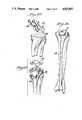
- FIG. 1illustrates the anatomical considerations of the legs which are taken into account in accordance with the invention
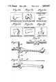
- FIGS. 2a through 2fillustrate the eight basic bone cuts which are made in accordance with the invention
- FIGS. 3-30illustrate the various steps and instruments used therein from incision to final tibial preparation in the practice of the invention
- FIGS. 31-35are side, top, front, bottom and rear views, respectively, of the distal femoral cutting jig shown in FIGS. 7-13;
- FIGS. 36-40are side, front, rear, bottom and plan views, respectively, of the pin holder alignment guide shown in FIGS. 8-9;
- FIGS. 41-44are cross-sectional views taken through FIG. 37 along the lines 41--41, 42--42, 43--43 and 44--44;
- FIG. 45is a front elevation view partly in section of the distal femoral cutting jig shown in FIGS. 10-13;
- FIGS. 46-49are top, bottom, side and rear views, respectively, of the femoral cutting jig shown in FIG. 45;
- FIG. 50is a cross-sectional view taken through FIG. 48 along the line 50--50;
- FIGS. 51-55are bottom, front, rear, side and top views, respectively, of the femoral drill jig shown in FIGS. 13-14;
- FIG. 56is a cross-sectional view taken through FIG. 52 along the line 56--56;
- FIGS. 57-61are top, front, rear, bottom and side views, respectively, of the transverse femoral cutting jig shown in FIGS. 15-16;
- FIG. 62is a cross-sectional view taken through FIG. 57 along the line 62--62;
- FIGS. 63-67are side, top, front, rear and bottom views, respectively, of the femoral spacer/tensor jig shown in FIGS. 17-22;
- FIGS. 69-72are top, rear, front and bottom elevation views, respectively, of the transverse tibial cutting jig shown in FIGS. 17-23;
- FIGS. 73-74are end elevation views of the transverse tibial cutting jig shown in FIGS. 29-72;
- FIG. 75is a cross-sectional view taken through FIG. 69 along the line 75--75;
- FIGS. 76-80are bottom, front, rear, top and end views, respectively, of the femoral chamfer cutting jig shown in FIG. 24;
- FIG. 81is a cross-sectional view taken through FIG. 76 along the line 81--81;
- FIG. 87is a cross-sectional view taken through FIG. 82 along the line 87--87;
- FIGS. 88-92are side, top, bottom, front and rear views, respectively, of the tibial positioning/fixation jig shown in FIGS. 25-30;
- FIG. 94is a cross-sectional view taken through FIG. 88 along the line 94--94.
- the instruments utilized in the practice of the inventionconsist of long axial alignment guides and cutting jigs.
- the jigsmay be sequentially numbered relative to their order of use to simplify the procedure.
- the alignment guidesare designed to assist the surgeon in positioning all primary cutting jigs prior to making the bone cuts. All cutting jigs lock onto their respective bones to insure the accuracy of the cuts.
- the inventive instrument systemis designed to seat the femoral and tibial components parallel to the anatomic transverse axis of the knee. Since this axis is parallel to the ground and perpendicular to the vertical in two-legged stance, this positioning achieves: (1) uniform stress distribution at fixation interfaces, (2) optimal alignment; and (3) physiological ligamentous balance of the knee. It is also important to recognize that the ankles remain closer to the midline vertical axis of the body that either the knees or hips throughout noral gait. To achieve the goals of total knee arthroplasty, these alignment features must be preserved or reconstituted.
- the inventive instrument systemuses the femoral shaft axis (S), the center of the knee (K), the center of the ankle joint (A), and the transverse axis of the knee (T) as its alignment references (FIG. 1).
- the mechanical axis of the lower limbwhich runs from the center of the hip (H) thorugh the center of the knee (K) to the center of the ankle (A), generally forms an angle of 3° with the vertical (V), because the hips are wider apart than the ankles in both normal stance and gait (FIG. 1).
- the axis of the femoral shaftdoes not coincide with that of the leg, but forms with the leg a more acute valgus angle of 6° (SKH, FIG. 1).
- the femoral shaft axisaverages 9° of valgus with the vertical.
- the valgus angle of the femurvaries relative to body build.
- the specific femoral valgus for a given individualcan be determined by measuring angle HKS (FIG. 1) on a long x-ray which includes both the hip and the knee, and adding 3° (the mechanical axis). This method is valid for reconstituting a mechanical axis of 3° regardless of the degree of pre-operative axial deformity at the knee.
- the center of the knee and the center of the ankleare used as reference points. Instruments which rely on the proximal tibial shaft as their key alignment reference tend to be inaccurate due to the frequent occurrence of tibial bowing. Recognizing that the center of the ankle is closer to the midline vertical axis than the center of the knee in two-legged stance and throughout gait, this system uniquely requires a small angle at the proximal transverse tibal cut (TKA, FIG. 1). This angle keeps the transverse axis of the prosthesis parallel to the ground while the mechanical axis of the entire lower extremity remains in valgus (HKA, FIG. 1).
- FIG. 2illustrates the eight basic bone cuts required to align and seat the femoral and tibial components of the prosthesis.
- the instrument systemconsists of seven sequentially numbered cutting jigs and a femoral/tibial alignment guide. These are designed to insure the accuracy and alignment of all femoral and tibial bone cuts.
- the kneeis approached through a longitudinal skin incision, followed by a medical parapatellar capsular incision.
- the quadriceps tendonis incised longitudinally, allowing eversion and dislocation of the patella laterally (FIG. 3).
- a 5/16 inch drill holeis made by drill bit 10 in the distal femur. It is placed roughly in the center 12 of the intercondylar notch just anterior to the femoral attachment of the posterior cruciate ligament (FIG. 4). The position of this hole 13 (FIG. 6) is not critical to the orientation of any femoral bone cuts--it is simply a point of purchase for the distal femoral cutting jig IA.
- the laterally protruding handles 22are used to rotate the jig so that the posterior rounded eminences parallel to the posterior femoral condyles and the anterior femur is seen as on a sunrise view (FIG. 5).
- Jig IAincludes a pair of locking pins on the side hidden from view in FIG. 5. If there has been significant preoperative deformity, the short locking pin facing the most prominent condyle is hammered into place bringing the face of the jig IA flush to that condyle only.
- the long axial alignment guide 16is used to establish proper varus-valgus and flexion extension alignment of the distal femoral cuts.
- the guide pin 18is positioned into the pin holder in the appropriate right or left 7°, 9° or 11° hole 20 (FIG. 37). This angle is chosen relative to the pre-operative x-ray measurement technique previously described in the alignment rationale section. Most often 9° will be appropriate.
- the guide 16is then placed into the anterior holes of the distal femoral cutting jig IA. Correct axial alignment is achieved when the long alignment guide pin 18 is parallel to the femoral shaft axis in both the anterior and lateral views (FIGS. 7 and 8).
- An examining fingercan be slipped proximally under the quadriceps to get a better idea of the direction of the femoral shaft during this alignment procedure. If the alignment pin 18 does not parallel the femoral shaft, a mallet is used to tap the medial handle 20 or lateral handle 22, advancing the jig IA away from the deformed condyle until the axial guide pin 18 parallels the femoral shaft (FIG. 9). With the alignment completed, one can easily visualize how much bone is missing from the deformed condyle. The IA jig is not stable at this point but must be manually held during insertion and removal of the alignment pinholder and also while placing the IB jig.
- a short alignment pinis available to facilitate alignment in two special circumstances.
- the shorter pinavoids impingement with the tourniquet on an obese thigh or with the abdomen of a short patient.
- the axial alignment guide 16is removed and the tongue of the distal femoral cutting jig IA and jig IB is slid into the first part of the distal femoral jig IA (FIG. 10).
- the teeth of the IB jigresting lightly on the anterior femur, recheck the alignment for both varus-valgus and flexion-extension prior to hammering it in place.
- There are also drill holes in the cutting bar of the IB jigthrough which 1/8 inch drill pins can be passed into the condyles if additional stability is necessary.
- This stepis important since the saw blade tends to scive away from the desired plane, particularly in more sclerotic bone and toward the deeper portions of the cut.
- the jigsare now removed and the distal femoral cuts are completed.
- the anterior aspect of the distal femoral cutwill serve as the "cutting block" for the remaining posterior aspect. It is, therefore, important that the saw blade be inserted to the full depth of the initial cut before the oscillation is started. Otherwise, one runs the risk of starting a new plane.
- the broadest bladeshould be passed over the surface to be sure that the cut is a single-flat plane. This can also be checked with a cutting block.
- Rotational, medial-lateral and anterior-posterior orientation of the femoral prosthesisis determined by the femoral drill jig II.
- This jighas two posterior skids 24 which are slid between the posterior femoral condyles and tibial plateaus. These skids automatically position the instrument in 0° of rotation relative to the coronal plane of the distal femur (A,A, FIG. 14).
- the jigshould first be centered in the medial-lateral position on the flat cut distal femoral surface, ignoring the initial keying hole for the IA jig.
- the jig IIis now hammered flush with the flat surface of the distal femoral condyles.
- the jig's anterior projectioncontains two holes 26 marked respectively for right and left knees.
- a 1/8 inch drill pin 28 placed in the appropriate holeis aligned with the center of the patello-femoral groove, correct medial-lateral and rotational positioning is assured (B,B, FIG. 14).
- a 5/16 inch drill 30is used to make the holes for the femoral prosthesis fixation studs (C,C, FIG. 14).
- the two 5/16 inch locking studs 32 of the anterior-posterior femoral cutting jig IIIare inserted into the distal femoral fixation holes.
- the jig IIIis hammered flush with the flat cut surface of the distal femoral condyles.
- the anterior plane of the cutting jigshould intersect the anterior cortex of the femur at the proximal margin of the patellar facets (FIG. 15). If this plane appears too deep or too anterior, the next most appropriate size jig should be chosen. If there is any question of which size jig is to be used, always start with the larger jig.
- anterior and posterior femoral bone cutsare now completed (FIG. 16). Once again, care must be taken to rest the saw blade flush against the flat surface of the jig. With the posterior condyles removed, complete access to the posterior compartment allows removal of the menisci and anterior cruciate ligament. The tibial attachment of the posterior cruciate is identified and carefully avoided during the next step. Also, all remaining marginal osteophyte on the tibia and femur must be removed so they do not shorten or constrict ligaments or block full extension.
- the femoral spacer/tensor jig IV and transverse tibial cutting jig Vare now assembled and positioned.
- the mortise cut out 34 in the transverse tibial cutting jig Vis slipped over the tongue 36 of the femoral spacer/tensor jig and slid as far proximally as it will go (FIG. 17).
- the legis brought into full extension.
- a folded towel or sheetis placed behind the knee to prevent inadvertent hyperextension at this stage of the procedure.
- the axial alignment guide 16with both its femoral and tibial alignment pins in place is positioned into the femoral spacer/tensor jig IV (FIG. 18).
- Soft tissue stabilityis established following initial manual tibial axial alignment.
- Each side of the femoral spacer/tensor jig IVhas expandable arms 38 which spread when its appropriate thumb screw 40 is tightened (FIG. 20).
- the tensor armsare extended to stabilize the joint in the correct alignment. Do not overtighten the femoral spacer/tensor jig IV.
- the transverse tibila cutting jig Vpushed as far proximally as it will go ensures that only the Minimal amount of the tibial plateaus will be removed.
- the transverse cutting jigWhen one plateau is considerably more depressed than the other, the transverse cutting jig should be slid distally so that the plane of the tibial cut will remove enough bone from the depressed plateau to provide a sufficiently flat surface for seating the tibial prosthesis.
- the femoral alignment pin 18will parallel the femoral shaft in both the anterior and lateral planes.
- the tibial alignment pin 19will extend from the center of the knee to the center of the ankle and be parallel to the tibial shaft, in the lateral plane. Rotation is correct when the medial malleolus is approximately 30° anterior to the lateral malleolus (FIG. 19).
- the transverse tibial cutting jig Vis locked in place by drilling two 1/8 inch pins through the appropriate holes in the jig (FIG. 21).
- the alignment guide 16is now removed and tension is removed from the jig IV by loosening the thumb screws 40.
- the femoral spacer/tensor jig IVwill pull out of its anchoring holes in the femur.
- the jig IVis then slipped proximally, disengaging it from the tibial cutting jig V (FIG. 22).
- the transverse tibial plateau cutis then made by resting the saw blade flush against the broad flat surface of the cutting jig V (FIG. 23). The cut is made as deeply as the saw blade will allow, while care is taken to protect collateral ligaments. Once again, following the initial cut of the oscillating saw blade should be run back and forth across the flat surface of the transverse cutting jig to shave off any prominent bone that may be left posteriorly due to sciving of the saw blade in sclerotic bone. The jig V is then slipped off the locking pins and the cut is completed, making sure that the posterior rims of the plateaus are level with the plane of the transverse cut. Additional care should be taken to preserve the posterior cruciate ligament. Since the transverse tibial cut is made parallel to the ground for optimal stress distribution as the prosthesis bone interface and because the normal tibial plateau slopes 7° to 10° posteriorly, more bone will be removed anteriorly than posteriorly.
- the femoral chamfer cutting jig VIis inserted then into the femoral fixation holes. With the saw blade flush against the jig's cutting planes 42, the anterior and posterior cuts are made (FIG. 24). As with other cutting jigs, it is important to maintain the saw blade perfectly flush with the cutting surfaces 42 of the jig to assure precise cuts, otherwise the femoral component will not fully seat.
- the kneeis extended and traction is applied from the foot to open the joint space.
- the posterior tabs of the appropriate sized tibial positioning/fixation jigs VIIare hooked behind the cut proximal tibia (FIG. 25).
- the two posterior tabs 44 of the jigposition behind the posterior rims of the tibial plateau, assuring correct posterior position of the tibial prosthesis.
- the kneeis then flexed and the jig VII is centrally positioned. Since the posterior margins of the tibial plateaus are nearly parallel to the transverse axis of the tibia, the posterior tabs 44 will position the jig in correct rotation.
- Rotational and medial-lateral positioningare checked by slipping an axial alignment guide pin 19 through the appropriate right or left alignment hole in the anterior flange of the jig.
- the two anterior thumb screws 46 of the jigare then lightly tightened, securing the jig in place. If alignment is correct, the distal tip of the alignment pin should center over the ankle joint with the medial malleolus 30° anterior to the lateral malleolus (FIG. 26). If this is not the case, the jig is manipulated into proper alignment. Rotational malalignment tends to be toward external rotation of the tibia.
- tibial trial prosthesis 48is inserted onto the jig (FIG. 27).
- the trial femoral prosthesisis then positioned onto the femur.
- Range of motion and stabilityare now tested. If the joint is too lax, the next thickest tibial trial is slipped onto the tibial positioning/fixation jig VII. Once flexion, rotation and stability are satisfactory, the overall alignment is checked in full extension FIGS. 28 and 29). The alignment guide is removed, and the knee is flexed to 90°. Next, the femoral trial and tibial spacer are removed. The thickness marked on the tibial trial spacer indicates the thickness of the prosthesis to be implanted.
- the window 50 in the jig VIIis used, as a cutting guide.
- a 1/2 inch osteotome 52is used to prepare the fixation slot while the jig is still locked onto the proximal tibia (FIG. 30).
- a 5/16 inch drill 54is used to make the stud holes through the drill guides in the jig VII (FIG. 30). With fixation peg or stud holes completed, the jig is removed. A final check of the joint is made for posterior loose bodies, and soft tissue debridement is completed.
- FIGS. 31-94illustrate in full scale various instruments used in accordance with this invention.
- FIGS. 31-35illustrate the distal femoral cutting jig IA which is used for achieving axial alignment when used with the axial adjustment guide 16.
- Distal femoral cutsare made when jig IA is used with cut jig IB.
- the side 55 of the central portion 56 of jig IAhas attached thereto a pair of lateral handles 22, 22 while a medial handle 20 also extends from the front face 57 of central section 56.
- a positioning pin 58is disposed on the rear face 61 of central section 56 as previously described. Attaching means are provided on the upper surface 59 of the central section 56 for selective attachment of the pin holder alignment guide 16.
- the attaching meansis in the form of a pair of holes 60, 62 which are of different diameter corresponding to the different diameter locking pins 64, 66 (FIG. 37) of the pin holder 16. In this manner there is assurance that the pin holder can be mounted in only the correct position.
- the rear surface 61 of central section 56also includes a pair of short alignment pins 68 as previously described.
- a vertical cut-out 70extends completely through central section 56 for receiving the tongue 72 (FIG. 45) of the distal femur cutting jig IB.
- An adjustable locking screw 74is movable into cut-out 70 to lock tongue 72 in place.
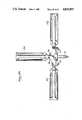
- FIGS. 36-44illustrate the details of pin holder 16 which is used with guide pins 18, 19 (FIG. 19) to assure correct axial alignment throughout the surgical procedure.
- Pin holder 16is in the form of an elongated bar and includes bifurcated pins 64, 66 to complement the holes 60, 62 in jig IA.
- the lower portion of pin holder 16is provided with a pair of mirror image tibial holes 76, 76 for selectively receiving tibial alignment pin 19.
- the holesare angled oppositely each other, as previously described, with one holder being for the right knee and the other being for the left knee.
- three sets of holes 78, 80, 82are provided for the femoral alignment pin 18.
- the holesare disposed at the most likely angle required such as 7°, 9° and 11° with one set being for the right knee and the other for the left knee.
- FIGS. 45-50illustrate the details of distal femoral cutting jig IB which is in the form of a plate or bar having a downwardly extending tongue 72 with non-symmetric cross-section of complementary size and shape to fit within the mortise cut-out 70 of jig IA.
- Jig IBis used for cutting the distal femoral condyles.
- Plate 84includes a pair of femoral securing pins 86 for attachment to the femur with two pairs of positioning pins 88 spaced inwardly thereof.
- the upper surface of plate 84is also provided with a pair of non-identical holes 90, 92 for receiving the locking pins 64, 66 of pin holder 16.
- Plate 84is also provided with a generally vertical guide surface 94 on each wing portion thereof to act as a saw cutting guide (see FIG. 13).
- a pair of vertical holes 96are provided in plate 84.
- FIGS. 51-56illustrate the femoral cutting jig II which is used to determine the rotational, medial-lateral and anterior-posterior orientation of the femoral component and allows drilling of holes for prosthesis fixation stud.
- jig IIis in the form of a generally vertical plate 98 having a flat inner surface 100.
- a pair of posterior skids 24extend outwardly from inner surface 100 at the lower portion thereof.
- a pair of drill holes 26extend through plate 98 as previously described. If the posterior condyles are intact, a hole may be drilled therein through the aid of one of the drill holes 102, 102 with holes 102, 102 being inclined for the right and left knee.
- Plate 98also includes a pair of positioning pins 104 on its inner surface 100.
- FIGS. 57-62illustrate the anterior-posterior cutting jig III.
- jig IIIis in the form of a bar or plate 106 which has a flat vertical surface 108.
- a pair of distal femoral fixation pins 32extend from surface 108.
- a generally horizontal lower cutting guide surface 110is also provided as well as an upwardly inclined cutting guide surface 112.
- a cut-out 114is located centrally of bar 106.
- jig IIIwould come in small, medium and large sizes.
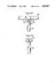
- FIGS. 63-68illustrate the details of femoral spacer/tensor jig IV which assembles and positions transverse tibial cutting jig V to determine correct soft tissue balance and tibial axial and rotational alignment prior to making the transverse tibial cut.
- Jig IVcomprises a pair of spaced fixed legs 116 with each leg having a lower vertical section and an inwardly inclined upper section.
- a transverse bridge member 118joins the fixed legs at the junction of the upper and lower sections.
- a pair of spaced parallel movable legs 38generally conform in size and shape to fixed legs 116 and are hingedly mounted at their ends thereof by hinge connection 102 to their respective movable legs.
- Adjusting means in the form of bolts or thumb screws 40are threadably engaged with and extend through fixed legs 116 into contact with movable legs 38 for controlling the spacing or relative positioning of the respective sets of legs.
- a pair of studs 126are provided at the lower portion of legs 116 while rounded contact surfaces 128 extend away from movable legs 38. Legs 38 may thus be moved so that surfaces 128 contact the tibia.
- Bridge member 118includes outwardly extending tongue 36 which is of non-symmetrical cross section for complementary engagement with mortise cut-out 34 in jig V (FIG. 17). Jig V could then slide in or out on tongue 36 to adjust for the length of cut.
- FIGS. 69-75illustrate transverse tibial cutting jig V which is in the form of a bar 130 having a flat upper cutting guide surface 132 and cut-out 34 for receiving tongue 36 of jig IV.
- a locking screw 134is movable into cut-out 34 to lock tongue 36 in place.
- a pair of vertical drill holes 136also extend through bar 130.
- FIGS. 76-81show one form of femoral chamfer cutting jig VI which is in the form of a bar 138 having its front face formed in three sections which include a pair of inclined upper and lower cutting guide surfaces 42 extending to the upper edge and lower edge of bar 138.
- the intermediate surface 140is generally vertical.
- a pair of positioning studs 142are provided to extend into the same medial alignment holes which are utilized by various other jigs.
- FIGS. 82-87show a modified form of jig VI wherein a condylar cut-out 144 is provided in the lower guide surface.
- jig VIwould come in five different sizes varying in size of the cut-out 144 and/or being sized small, medium or large.
- FIGS. 88-94illustrate the tibial positioning/fixation jig VII.
- Jig VIIgenerally includes a plate 146 having a lower planar surface 148 from which extend a pair parallel tabs 44.
- An osteotome cut-out or window 50is provided in the central portion thereof with an inclined drill hole 150 on each side of cut-out 50.
- a block 152is connected to plate 146.
- a pair of vertical alignment holes 154which are inclined for the right and left knee extend through block 152.
- thumb screws 46are threadedly mounted into and extend through block 152 while a pair of non-identical holes 156, 158 are provided in block 152 for receiving the locking pins 64, 66 of holder 16.
Landscapes
- Health & Medical Sciences (AREA)
- Life Sciences & Earth Sciences (AREA)
- Surgery (AREA)
- Dentistry (AREA)
- Biomedical Technology (AREA)
- Oral & Maxillofacial Surgery (AREA)
- Nuclear Medicine, Radiotherapy & Molecular Imaging (AREA)
- Physical Education & Sports Medicine (AREA)
- Orthopedic Medicine & Surgery (AREA)
- Engineering & Computer Science (AREA)
- Transplantation (AREA)
- Heart & Thoracic Surgery (AREA)
- Medical Informatics (AREA)
- Molecular Biology (AREA)
- Animal Behavior & Ethology (AREA)
- General Health & Medical Sciences (AREA)
- Public Health (AREA)
- Veterinary Medicine (AREA)
- Prostheses (AREA)
Abstract
Description
Claims (21)
Priority Applications (1)
| Application Number | Priority Date | Filing Date | Title |
|---|---|---|---|
| US06/837,200US4825857A (en) | 1982-02-18 | 1986-03-10 | Prosthetic knee implantation |
Applications Claiming Priority (3)
| Application Number | Priority Date | Filing Date | Title |
|---|---|---|---|
| US35001382A | 1982-02-18 | 1982-02-18 | |
| US68511184A | 1984-12-21 | 1984-12-21 | |
| US06/837,200US4825857A (en) | 1982-02-18 | 1986-03-10 | Prosthetic knee implantation |
Related Parent Applications (1)
| Application Number | Title | Priority Date | Filing Date |
|---|---|---|---|
| US68511184AContinuation | 1982-02-18 | 1984-12-21 |
Publications (1)
| Publication Number | Publication Date |
|---|---|
| US4825857Atrue US4825857A (en) | 1989-05-02 |
Family
ID=27407920
Family Applications (1)
| Application Number | Title | Priority Date | Filing Date |
|---|---|---|---|
| US06/837,200Expired - LifetimeUS4825857A (en) | 1982-02-18 | 1986-03-10 | Prosthetic knee implantation |
Country Status (1)
| Country | Link |
|---|---|
| US (1) | US4825857A (en) |
Cited By (77)
| Publication number | Priority date | Publication date | Assignee | Title |
|---|---|---|---|---|
| US5171244A (en)* | 1990-01-08 | 1992-12-15 | Caspari Richard B | Methods and apparatus for arthroscopic prosthetic knee replacement |
| US5431660A (en)* | 1993-11-30 | 1995-07-11 | Burke; Dennis W. | Spring loaded screw and driver/extractor therefor |
| US5431653A (en)* | 1993-07-06 | 1995-07-11 | Callaway; George H. | Knee joint flexion-gap distraction device |
| US5514143A (en)* | 1991-11-27 | 1996-05-07 | Apogee Medical Products, Inc. | Apparatus and method for use during surgery |
| US5562674A (en)* | 1995-02-27 | 1996-10-08 | Zimmer, Inc. | Intramedullary rod with guide member locator |
| US5569255A (en)* | 1992-11-20 | 1996-10-29 | Burke; Dennis W. | Method for implanting a prosthetic device into a bone |
| US5569259A (en)* | 1992-02-20 | 1996-10-29 | Wright Medical Technology, Inc. | Modular shaping and trial reduction guide for implantation of femoral prosthesis and method of using same |
| EP0780093A1 (en)* | 1995-12-21 | 1997-06-25 | JOHNSON & JOHNSON PROFESSIONAL Inc. | Quick-release tibial tray handle |
| EP0780092A1 (en)* | 1995-12-21 | 1997-06-25 | JOHNSON & JOHNSON PROFESSIONAL Inc. | Punch system for tibial prosthesis |
| US5649929A (en)* | 1995-07-10 | 1997-07-22 | Callaway; George Hadley | Knee joint flexion-gap distraction device |
| US5702485A (en)* | 1992-11-20 | 1997-12-30 | Burke; Dennis W. | Collared prosthetic device with centering fins |
| US5733292A (en)* | 1995-09-15 | 1998-03-31 | Midwest Orthopaedic Research Foundation | Arthroplasty trial prosthesis alignment devices and associated methods |
| US5830216A (en)* | 1996-10-30 | 1998-11-03 | Bristol-Myers Squibb Company | Apparatus and method for knee implantation |
| US5925049A (en)* | 1996-02-23 | 1999-07-20 | Midwest Orthopedic Research Foundation | Device and method for distal femur cutting and prosthesis measuring |
| US5951606A (en)* | 1992-11-20 | 1999-09-14 | Burke; Dennis W. | Centering device for femoral implant and method and apparatus for implementation thereof |
| US6152410A (en)* | 1997-10-06 | 2000-11-28 | Soheil Mosun Limited | Hinged bracket |
| WO2001066021A1 (en)* | 2000-03-10 | 2001-09-13 | Smith & Nephew, Inc | A method of arthroplasty on a knee joint and apparatus for use in same |
| US20040102785A1 (en)* | 2002-11-27 | 2004-05-27 | Hodorek Robert A. | Method and apparatus for achieving correct limb alignment in unicondylar knee arthroplasty |
| US20040153162A1 (en)* | 2003-02-04 | 2004-08-05 | Sanford Adam H. | Provisional orthopedic prosthesis for partially resected bone |
| US20040249387A1 (en)* | 2003-04-25 | 2004-12-09 | Francisco Faoro | Apparatus for the preparation of a femoral condyle |
| US20050027226A1 (en)* | 2003-05-06 | 2005-02-03 | Centerpulse Orthopedics Ltd. | Traction apparatus |
| US20050049603A1 (en)* | 2002-07-23 | 2005-03-03 | Ortho Development Corporation | Knee balancing block |
| US20050059980A1 (en)* | 2003-09-15 | 2005-03-17 | Centerpulse Orthopedics Ltd. | Adjustment apparatus |
| US20050143746A1 (en)* | 2003-12-26 | 2005-06-30 | Steffensmeier Scott J. | Adjustable resection guide |
| US20060155293A1 (en)* | 2005-01-07 | 2006-07-13 | Zimmer Technology | External rotation cut guide |
| US20060173463A1 (en)* | 2004-12-21 | 2006-08-03 | Dees Roger R Jr | Distal femoral trial with removable cutting guide |
| US20070173854A1 (en)* | 2006-01-23 | 2007-07-26 | Berger Richard A | Bone resection apparatus and method for knee surgery |
| US20080147075A1 (en)* | 2000-01-14 | 2008-06-19 | Peter M Bonutti | Minimally Invasive Surgical Systems and Methods |
| US20080195108A1 (en)* | 2007-02-12 | 2008-08-14 | Jmea Corporation | Total Knee Arthoplasty System |
| US20080287958A1 (en)* | 2007-05-14 | 2008-11-20 | Howmedica Osteonics Corp. | Flexible intramedullary rod |
| US20090131941A1 (en)* | 2002-05-15 | 2009-05-21 | Ilwhan Park | Total joint arthroplasty system |
| US20090326544A1 (en)* | 2008-06-27 | 2009-12-31 | Ryan Chessar | Knee ligament balancer |
| US7799084B2 (en) | 2002-10-23 | 2010-09-21 | Mako Surgical Corp. | Modular femoral component for a total knee joint replacement for minimally invasive implantation |
| US20100249658A1 (en)* | 2009-03-31 | 2010-09-30 | Sherman Jason T | Device and method for determining force of a knee joint |
| US7959635B1 (en) | 2000-01-14 | 2011-06-14 | Marctec, Llc. | Limited incision total joint replacement methods |
| US20110214279A1 (en)* | 2007-12-18 | 2011-09-08 | Otismed Corporation | Preoperatively planning an arthroplasty procedure and generating a corresponding patient specific arthroplasty resection guide |
| US8167888B2 (en) | 2004-08-06 | 2012-05-01 | Zimmer Technology, Inc. | Tibial spacer blocks and femoral cutting guide |
| US20130041376A1 (en)* | 2011-08-12 | 2013-02-14 | Zimmer, Inc. | Prosthesis resection guide |
| US8460303B2 (en) | 2007-10-25 | 2013-06-11 | Otismed Corporation | Arthroplasty systems and devices, and related methods |
| US8460302B2 (en) | 2006-12-18 | 2013-06-11 | Otismed Corporation | Arthroplasty devices and related methods |
| US8480679B2 (en) | 2008-04-29 | 2013-07-09 | Otismed Corporation | Generation of a computerized bone model representative of a pre-degenerated state and useable in the design and manufacture of arthroplasty devices |
| US8483469B2 (en) | 2008-04-30 | 2013-07-09 | Otismed Corporation | System and method for image segmentation in generating computer models of a joint to undergo arthroplasty |
| US8532361B2 (en) | 2008-04-30 | 2013-09-10 | Otismed Corporation | System and method for image segmentation in generating computer models of a joint to undergo arthroplasty |
| USD691719S1 (en) | 2007-10-25 | 2013-10-15 | Otismed Corporation | Arthroplasty jig blank |
| US8556830B2 (en) | 2009-03-31 | 2013-10-15 | Depuy | Device and method for displaying joint force data |
| US8597210B2 (en) | 2009-03-31 | 2013-12-03 | Depuy (Ireland) | System and method for displaying joint force data |
| US8617175B2 (en) | 2008-12-16 | 2013-12-31 | Otismed Corporation | Unicompartmental customized arthroplasty cutting jigs and methods of making the same |
| US8623030B2 (en) | 2001-08-28 | 2014-01-07 | Bonutti Skeletal Innovations Llc | Robotic arthroplasty system including navigation |
| US8715291B2 (en) | 2007-12-18 | 2014-05-06 | Otismed Corporation | Arthroplasty system and related methods |
| US8721568B2 (en) | 2009-03-31 | 2014-05-13 | Depuy (Ireland) | Method for performing an orthopaedic surgical procedure |
| US8737700B2 (en) | 2007-12-18 | 2014-05-27 | Otismed Corporation | Preoperatively planning an arthroplasty procedure and generating a corresponding patient specific arthroplasty resection guide |
| US8734455B2 (en) | 2008-02-29 | 2014-05-27 | Otismed Corporation | Hip resurfacing surgical guide tool |
| US8740817B2 (en) | 2009-03-31 | 2014-06-03 | Depuy (Ireland) | Device and method for determining forces of a patient's joint |
| US8747439B2 (en) | 2000-03-13 | 2014-06-10 | P Tech, Llc | Method of using ultrasonic vibration to secure body tissue with fastening element |
| US8777875B2 (en) | 2008-07-23 | 2014-07-15 | Otismed Corporation | System and method for manufacturing arthroplasty jigs having improved mating accuracy |
| US8808329B2 (en) | 1998-02-06 | 2014-08-19 | Bonutti Skeletal Innovations Llc | Apparatus and method for securing a portion of a body |
| US8814902B2 (en) | 2000-05-03 | 2014-08-26 | Bonutti Skeletal Innovations Llc | Method of securing body tissue |
| US8845699B2 (en) | 1999-08-09 | 2014-09-30 | Bonutti Skeletal Innovations Llc | Method of securing tissue |
| US8845687B2 (en) | 1996-08-19 | 2014-09-30 | Bonutti Skeletal Innovations Llc | Anchor for securing a suture |
| US8968320B2 (en) | 2007-12-18 | 2015-03-03 | Otismed Corporation | System and method for manufacturing arthroplasty jigs |
| US9017336B2 (en) | 2006-02-15 | 2015-04-28 | Otismed Corporation | Arthroplasty devices and related methods |
| US9119734B2 (en) | 2006-10-31 | 2015-09-01 | Smith & Nephew, Inc. | Trial femoral prosthesis and its use |
| US20160074053A1 (en)* | 2010-08-11 | 2016-03-17 | Biomet Manufacturing, Llc. | Ligament balancer and drill guide |
| US9381011B2 (en) | 2012-03-29 | 2016-07-05 | Depuy (Ireland) | Orthopedic surgical instrument for knee surgery |
| US9402637B2 (en) | 2012-10-11 | 2016-08-02 | Howmedica Osteonics Corporation | Customized arthroplasty cutting guides and surgical methods using the same |
| US9545459B2 (en) | 2012-03-31 | 2017-01-17 | Depuy Ireland Unlimited Company | Container for surgical instruments and system including same |
| US9649170B2 (en) | 2007-12-18 | 2017-05-16 | Howmedica Osteonics Corporation | Arthroplasty system and related methods |
| US9770272B2 (en) | 2012-12-12 | 2017-09-26 | Wright Medical Technology, Inc. | Orthopedic compression/distraction device |
| US9770238B2 (en) | 2001-12-03 | 2017-09-26 | P Tech, Llc | Magnetic positioning apparatus |
| US9808262B2 (en) | 2006-02-15 | 2017-11-07 | Howmedica Osteonics Corporation | Arthroplasty devices and related methods |
| US10070973B2 (en) | 2012-03-31 | 2018-09-11 | Depuy Ireland Unlimited Company | Orthopaedic sensor module and system for determining joint forces of a patient's knee joint |
| US10098761B2 (en) | 2012-03-31 | 2018-10-16 | DePuy Synthes Products, Inc. | System and method for validating an orthopaedic surgical plan |
| US10105242B2 (en) | 2011-09-07 | 2018-10-23 | Depuy Ireland Unlimited Company | Surgical instrument and method |
| US10206792B2 (en) | 2012-03-31 | 2019-02-19 | Depuy Ireland Unlimited Company | Orthopaedic surgical system for determining joint forces of a patients knee joint |
| US10357255B2 (en) | 2015-10-08 | 2019-07-23 | Howmedica Osteonics Corp. | Globalized total knee instrumentation |
| US10582934B2 (en) | 2007-11-27 | 2020-03-10 | Howmedica Osteonics Corporation | Generating MRI images usable for the creation of 3D bone models employed to make customized arthroplasty jigs |
| US11123085B2 (en) | 2018-04-11 | 2021-09-21 | Howmedica Osteonics Corp. | Cutting tool positioned by flexible rod for revision surgery |
Citations (7)
| Publication number | Priority date | Publication date | Assignee | Title |
|---|---|---|---|---|
| US4457307A (en)* | 1982-08-20 | 1984-07-03 | Stillwell William T | Bone cutting device for total knee replacement |
| US4487203A (en)* | 1981-11-03 | 1984-12-11 | Androphy Gary W | Triplanar knee resection method |
| US4502483A (en)* | 1983-03-09 | 1985-03-05 | Dow Corning Corporation | Method and apparatus for shaping a distal femoral surface |
| US4567886A (en)* | 1983-01-06 | 1986-02-04 | Petersen Thomas D | Flexion spacer guide for fitting a knee prosthesis |
| US4567885A (en)* | 1981-11-03 | 1986-02-04 | Androphy Gary W | Triplanar knee resection system |
| US4646729A (en)* | 1982-02-18 | 1987-03-03 | Howmedica, Inc. | Prosthetic knee implantation |
| US4653488A (en)* | 1982-02-18 | 1987-03-31 | Howmedica, Inc. | Prosthetic knee implantation |
- 1986
- 1986-03-10USUS06/837,200patent/US4825857A/ennot_activeExpired - Lifetime
Patent Citations (7)
| Publication number | Priority date | Publication date | Assignee | Title |
|---|---|---|---|---|
| US4487203A (en)* | 1981-11-03 | 1984-12-11 | Androphy Gary W | Triplanar knee resection method |
| US4567885A (en)* | 1981-11-03 | 1986-02-04 | Androphy Gary W | Triplanar knee resection system |
| US4646729A (en)* | 1982-02-18 | 1987-03-03 | Howmedica, Inc. | Prosthetic knee implantation |
| US4653488A (en)* | 1982-02-18 | 1987-03-31 | Howmedica, Inc. | Prosthetic knee implantation |
| US4457307A (en)* | 1982-08-20 | 1984-07-03 | Stillwell William T | Bone cutting device for total knee replacement |
| US4567886A (en)* | 1983-01-06 | 1986-02-04 | Petersen Thomas D | Flexion spacer guide for fitting a knee prosthesis |
| US4502483A (en)* | 1983-03-09 | 1985-03-05 | Dow Corning Corporation | Method and apparatus for shaping a distal femoral surface |
Cited By (167)
| Publication number | Priority date | Publication date | Assignee | Title |
|---|---|---|---|---|
| US5228459A (en)* | 1990-01-08 | 1993-07-20 | Caspari Richard B | Method of resecting bone |
| US5263498A (en)* | 1990-01-08 | 1993-11-23 | Caspari Richard B | Method of arthroscopically preparing an articular bone surface |
| US5304181A (en)* | 1990-01-08 | 1994-04-19 | Caspari Richard B | Methods and apparatus for arthroscopic prosthetic knee replacement |
| US5395376A (en)* | 1990-01-08 | 1995-03-07 | Caspari; Richard B. | Method of implanting a prosthesis |
| US5171244A (en)* | 1990-01-08 | 1992-12-15 | Caspari Richard B | Methods and apparatus for arthroscopic prosthetic knee replacement |
| US5514143A (en)* | 1991-11-27 | 1996-05-07 | Apogee Medical Products, Inc. | Apparatus and method for use during surgery |
| US5569259A (en)* | 1992-02-20 | 1996-10-29 | Wright Medical Technology, Inc. | Modular shaping and trial reduction guide for implantation of femoral prosthesis and method of using same |
| US5951606A (en)* | 1992-11-20 | 1999-09-14 | Burke; Dennis W. | Centering device for femoral implant and method and apparatus for implementation thereof |
| US5569255A (en)* | 1992-11-20 | 1996-10-29 | Burke; Dennis W. | Method for implanting a prosthetic device into a bone |
| US5624443A (en)* | 1992-11-20 | 1997-04-29 | Burke; Dennis W. | Clamp for femoral implant |
| US6179877B1 (en) | 1992-11-20 | 2001-01-30 | Dennis W. Burke | Centering device for femoral implant and method and apparatus for implementation thereof |
| US5702485A (en)* | 1992-11-20 | 1997-12-30 | Burke; Dennis W. | Collared prosthetic device with centering fins |
| US5725596A (en)* | 1992-11-20 | 1998-03-10 | Burke; Dennis W. | Clamp for use with a bone prosthesis |
| US5431653A (en)* | 1993-07-06 | 1995-07-11 | Callaway; George H. | Knee joint flexion-gap distraction device |
| US5431660A (en)* | 1993-11-30 | 1995-07-11 | Burke; Dennis W. | Spring loaded screw and driver/extractor therefor |
| US5562674A (en)* | 1995-02-27 | 1996-10-08 | Zimmer, Inc. | Intramedullary rod with guide member locator |
| US5649929A (en)* | 1995-07-10 | 1997-07-22 | Callaway; George Hadley | Knee joint flexion-gap distraction device |
| US5733292A (en)* | 1995-09-15 | 1998-03-31 | Midwest Orthopaedic Research Foundation | Arthroplasty trial prosthesis alignment devices and associated methods |
| EP0780092A1 (en)* | 1995-12-21 | 1997-06-25 | JOHNSON & JOHNSON PROFESSIONAL Inc. | Punch system for tibial prosthesis |
| US5733290A (en)* | 1995-12-21 | 1998-03-31 | Johnson & Johnson Professional, Inc. | Quick-release tibial alignment handle |
| US5690636A (en)* | 1995-12-21 | 1997-11-25 | Johnson & Johnson Professional, Inc. | Punch system for tibial prosthesis |
| EP0780093A1 (en)* | 1995-12-21 | 1997-06-25 | JOHNSON & JOHNSON PROFESSIONAL Inc. | Quick-release tibial tray handle |
| US5925049A (en)* | 1996-02-23 | 1999-07-20 | Midwest Orthopedic Research Foundation | Device and method for distal femur cutting and prosthesis measuring |
| US8845687B2 (en) | 1996-08-19 | 2014-09-30 | Bonutti Skeletal Innovations Llc | Anchor for securing a suture |
| US5830216A (en)* | 1996-10-30 | 1998-11-03 | Bristol-Myers Squibb Company | Apparatus and method for knee implantation |
| US6152410A (en)* | 1997-10-06 | 2000-11-28 | Soheil Mosun Limited | Hinged bracket |
| US8808329B2 (en) | 1998-02-06 | 2014-08-19 | Bonutti Skeletal Innovations Llc | Apparatus and method for securing a portion of a body |
| US8845699B2 (en) | 1999-08-09 | 2014-09-30 | Bonutti Skeletal Innovations Llc | Method of securing tissue |
| US8784495B2 (en) | 2000-01-14 | 2014-07-22 | Bonutti Skeletal Innovations Llc | Segmental knee arthroplasty |
| US8632552B2 (en) | 2000-01-14 | 2014-01-21 | Bonutti Skeletal Innovations Llc | Method of preparing a femur and tibia in knee arthroplasty |
| US7510557B1 (en)* | 2000-01-14 | 2009-03-31 | Bonutti Research Inc. | Cutting guide |
| US8425522B2 (en) | 2000-01-14 | 2013-04-23 | Bonutti Skeletal Innovations Llc | Joint replacement method |
| US9101443B2 (en) | 2000-01-14 | 2015-08-11 | Bonutti Skeletal Innovations Llc | Methods for robotic arthroplasty |
| US9192459B2 (en) | 2000-01-14 | 2015-11-24 | Bonutti Skeletal Innovations Llc | Method of performing total knee arthroplasty |
| US8133229B1 (en) | 2000-01-14 | 2012-03-13 | Marctec, Llc. | Knee arthroplasty method |
| US7959635B1 (en) | 2000-01-14 | 2011-06-14 | Marctec, Llc. | Limited incision total joint replacement methods |
| US7931690B1 (en) | 2000-01-14 | 2011-04-26 | Marctec, Llc | Method of resurfacing an articular surface of a bone |
| US7892236B1 (en) | 2000-01-14 | 2011-02-22 | Marctec, Llc | System and method for total joint replacement |
| US7837736B2 (en) | 2000-01-14 | 2010-11-23 | Marctec, Llc | Minimally invasive surgical systems and methods |
| US7828852B2 (en) | 2000-01-14 | 2010-11-09 | Marctec, Llc. | Inlaid articular implant |
| US7806897B1 (en) | 2000-01-14 | 2010-10-05 | Marctec, Llc | Knee arthroplasty and preservation of the quadriceps mechanism |
| US9795394B2 (en) | 2000-01-14 | 2017-10-24 | Bonutti Skeletal Innovations Llc | Method for placing implant using robotic system |
| US7749229B1 (en) | 2000-01-14 | 2010-07-06 | Marctec, Llc | Total knee arthroplasty through shortened incision |
| US7708740B1 (en) | 2000-01-14 | 2010-05-04 | Marctec, Llc | Method for total knee arthroplasty and resecting bone in situ |
| US7635390B1 (en) | 2000-01-14 | 2009-12-22 | Marctec, Llc | Joint replacement component having a modular articulating surface |
| US7615054B1 (en) | 2000-01-14 | 2009-11-10 | Martec, LLC | Bicompartmental knee implant and method |
| US20080147075A1 (en)* | 2000-01-14 | 2008-06-19 | Peter M Bonutti | Minimally Invasive Surgical Systems and Methods |
| US8092462B2 (en) | 2000-03-10 | 2012-01-10 | Smith & Nephew, Inc. | Spacer for use in arthroplasty on a knee joint |
| US20030130665A1 (en)* | 2000-03-10 | 2003-07-10 | Pinczewski Leo Arieh | Method of arthroplastly on a knee joint and apparatus for use in same |
| US9439660B2 (en) | 2000-03-10 | 2016-09-13 | Smith & Nephew, Inc. | Method of arthroplasty on a knee joint and apparatus for use in same |
| US8690882B2 (en) | 2000-03-10 | 2014-04-08 | Smith & Nephew, Inc. | Method of arthroplasty on a knee joint and apparatus for use in same |
| US8323287B2 (en) | 2000-03-10 | 2012-12-04 | Smith & Nephew, Inc. | Apparatus for use in arthroplasty on a knee joint |
| US7371240B2 (en) | 2000-03-10 | 2008-05-13 | Smith & Nephew, Inc. | Method of arthroplasty on a knee joint and apparatus for use in same |
| US6969393B2 (en) | 2000-03-10 | 2005-11-29 | Smith & Nephew, Inc. | Apparatus for use in arthroplasty of the knees |
| US20070239167A1 (en)* | 2000-03-10 | 2007-10-11 | Smith & Nephew, Inc. | Method of arthroplasty on a knee joint and apparatus for use in same |
| US20060167460A1 (en)* | 2000-03-10 | 2006-07-27 | Pinczewski Leo A | Method of arthroplastly on a knee joint and apparatus for use in same |
| WO2001066021A1 (en)* | 2000-03-10 | 2001-09-13 | Smith & Nephew, Inc | A method of arthroplasty on a knee joint and apparatus for use in same |
| US8747439B2 (en) | 2000-03-13 | 2014-06-10 | P Tech, Llc | Method of using ultrasonic vibration to secure body tissue with fastening element |
| US8814902B2 (en) | 2000-05-03 | 2014-08-26 | Bonutti Skeletal Innovations Llc | Method of securing body tissue |
| US8858557B2 (en) | 2001-08-28 | 2014-10-14 | Bonutti Skeletal Innovations Llc | Method of preparing a femur and tibia in knee arthroplasty |
| US9763683B2 (en) | 2001-08-28 | 2017-09-19 | Bonutti Skeletal Innovations Llc | Method for performing surgical procedures using optical cutting guides |
| US10470780B2 (en) | 2001-08-28 | 2019-11-12 | Bonutti Skeletal Innovations Llc | Systems and methods for ligament balancing in robotic surgery |
| US9060797B2 (en) | 2001-08-28 | 2015-06-23 | Bonutti Skeletal Innovations Llc | Method of preparing a femur and tibia in knee arthroplasty |
| US8623030B2 (en) | 2001-08-28 | 2014-01-07 | Bonutti Skeletal Innovations Llc | Robotic arthroplasty system including navigation |
| US10231739B1 (en) | 2001-08-28 | 2019-03-19 | Bonutti Skeletal Innovations Llc | System and method for robotic surgery |
| US8834490B2 (en) | 2001-08-28 | 2014-09-16 | Bonutti Skeletal Innovations Llc | Method for robotic arthroplasty using navigation |
| US8840629B2 (en) | 2001-08-28 | 2014-09-23 | Bonutti Skeletal Innovations Llc | Robotic arthroplasty system including navigation |
| US10321918B2 (en) | 2001-08-28 | 2019-06-18 | Bonutti Skeletal Innovations Llc | Methods for robotic surgery using a cannula |
| US8641726B2 (en) | 2001-08-28 | 2014-02-04 | Bonutti Skeletal Innovations Llc | Method for robotic arthroplasty using navigation |
| US9770238B2 (en) | 2001-12-03 | 2017-09-26 | P Tech, Llc | Magnetic positioning apparatus |
| US8801719B2 (en) | 2002-05-15 | 2014-08-12 | Otismed Corporation | Total joint arthroplasty system |
| US20090131941A1 (en)* | 2002-05-15 | 2009-05-21 | Ilwhan Park | Total joint arthroplasty system |
| US8801720B2 (en) | 2002-05-15 | 2014-08-12 | Otismed Corporation | Total joint arthroplasty system |
| US7628793B2 (en) | 2002-07-23 | 2009-12-08 | Ortho Development Corporation | Knee balancing block |
| US20050049603A1 (en)* | 2002-07-23 | 2005-03-03 | Ortho Development Corporation | Knee balancing block |
| US7799084B2 (en) | 2002-10-23 | 2010-09-21 | Mako Surgical Corp. | Modular femoral component for a total knee joint replacement for minimally invasive implantation |
| EP1424042A3 (en)* | 2002-11-27 | 2004-08-25 | Zimmer Technology, Inc. | Apparatus for achieving correct limb alignment in unicondylar knee arthroplasty |
| US20040102785A1 (en)* | 2002-11-27 | 2004-05-27 | Hodorek Robert A. | Method and apparatus for achieving correct limb alignment in unicondylar knee arthroplasty |
| US20060247647A1 (en)* | 2002-11-27 | 2006-11-02 | Zimmer Technology, Inc. | Method and apparatus for achieving correct limb alignment in unicondylar knee arthroplasty |
| US20060241637A1 (en)* | 2002-11-27 | 2006-10-26 | Zimmer Technology, Inc. | Method and apparatus for achieving correct limb alignment in unicondylar knee arthroplasty |
| US7094241B2 (en) | 2002-11-27 | 2006-08-22 | Zimmer Technology, Inc. | Method and apparatus for achieving correct limb alignment in unicondylar knee arthroplasty |
| US7842039B2 (en) | 2002-11-27 | 2010-11-30 | Zimmer Technology, Inc. | Method and apparatus for achieving correct limb alignment in unicondylar knee arthroplasty |
| US8454616B2 (en) | 2002-11-27 | 2013-06-04 | Zimmer, Inc. | Method and apparatus for achieving correct limb alignment in unicondylar knee arthroplasty |
| US20040153162A1 (en)* | 2003-02-04 | 2004-08-05 | Sanford Adam H. | Provisional orthopedic prosthesis for partially resected bone |
| US6916324B2 (en)* | 2003-02-04 | 2005-07-12 | Zimmer Technology, Inc. | Provisional orthopedic prosthesis for partially resected bone |
| US7527630B2 (en) | 2003-04-25 | 2009-05-05 | Zimmer, Gmbh | Apparatus for the preparation of a femoral condyle |
| US20040249387A1 (en)* | 2003-04-25 | 2004-12-09 | Francisco Faoro | Apparatus for the preparation of a femoral condyle |
| US20050027226A1 (en)* | 2003-05-06 | 2005-02-03 | Centerpulse Orthopedics Ltd. | Traction apparatus |
| US7686813B2 (en) | 2003-05-06 | 2010-03-30 | Zimmer, Gmbh | Traction apparatus |
| US7648510B2 (en) | 2003-09-15 | 2010-01-19 | Zimmer, Gmbh | Adjustment apparatus |
| US20050059980A1 (en)* | 2003-09-15 | 2005-03-17 | Centerpulse Orthopedics Ltd. | Adjustment apparatus |
| US7641661B2 (en) | 2003-12-26 | 2010-01-05 | Zimmer Technology, Inc. | Adjustable resection guide |
| US20050143746A1 (en)* | 2003-12-26 | 2005-06-30 | Steffensmeier Scott J. | Adjustable resection guide |
| US8167888B2 (en) | 2004-08-06 | 2012-05-01 | Zimmer Technology, Inc. | Tibial spacer blocks and femoral cutting guide |
| US20110213378A1 (en)* | 2004-12-21 | 2011-09-01 | Smith & Nephew, Inc. | Distal femoral trial with removable cutting guide |
| US9649205B2 (en) | 2004-12-21 | 2017-05-16 | Smith & Nephew, Inc. | Distal femoral trial with removable cutting guide |
| US20060173463A1 (en)* | 2004-12-21 | 2006-08-03 | Dees Roger R Jr | Distal femoral trial with removable cutting guide |
| US9044249B2 (en) | 2004-12-21 | 2015-06-02 | Smith & Nephew, Inc. | Distal femoral trial with removable cutting guide |
| US7963968B2 (en) | 2004-12-21 | 2011-06-21 | Smith & Nephew, Inc. | Distal femoral trial with removable cutting guide |
| US8764759B2 (en) | 2004-12-21 | 2014-07-01 | Smith & Nephew, Inc. | Distal femoral trial with removable cutting guide |
| US20060155293A1 (en)* | 2005-01-07 | 2006-07-13 | Zimmer Technology | External rotation cut guide |
| US7780671B2 (en)* | 2006-01-23 | 2010-08-24 | Zimmer Technology, Inc. | Bone resection apparatus and method for knee surgery |
| US20070173854A1 (en)* | 2006-01-23 | 2007-07-26 | Berger Richard A | Bone resection apparatus and method for knee surgery |
| US20100286699A1 (en)* | 2006-01-23 | 2010-11-11 | Zimmer Technology, Inc. | Bone resection apparatus and method for knee surgery |
| US9017336B2 (en) | 2006-02-15 | 2015-04-28 | Otismed Corporation | Arthroplasty devices and related methods |
| US9808262B2 (en) | 2006-02-15 | 2017-11-07 | Howmedica Osteonics Corporation | Arthroplasty devices and related methods |
| US9119734B2 (en) | 2006-10-31 | 2015-09-01 | Smith & Nephew, Inc. | Trial femoral prosthesis and its use |
| US10010422B2 (en) | 2006-10-31 | 2018-07-03 | Smith & Nephew, Inc. | Trial femoral prosthesis and its use |
| US8460302B2 (en) | 2006-12-18 | 2013-06-11 | Otismed Corporation | Arthroplasty devices and related methods |
| US20080195108A1 (en)* | 2007-02-12 | 2008-08-14 | Jmea Corporation | Total Knee Arthoplasty System |
| US8313530B2 (en) | 2007-02-12 | 2012-11-20 | Jmea Corporation | Total knee arthroplasty system |
| US20110137316A1 (en)* | 2007-02-12 | 2011-06-09 | Jmea Corporation | Total Knee Arthroplasty Method |
| US8409210B2 (en) | 2007-02-12 | 2013-04-02 | Jmea Corporation | Total knee arthroplasty method |
| US20080287958A1 (en)* | 2007-05-14 | 2008-11-20 | Howmedica Osteonics Corp. | Flexible intramedullary rod |
| US8900233B2 (en) | 2007-05-14 | 2014-12-02 | Howmedica Osteonics Corp. | Flexible intramedullary rod |
| US20100241121A1 (en)* | 2007-05-14 | 2010-09-23 | Howmedica Osteonics Corp. | Flexible intramedullary rod |
| US9526541B2 (en) | 2007-05-14 | 2016-12-27 | Howmedica Osteonics Corp. | Flexible intramedullary rod |
| USD691719S1 (en) | 2007-10-25 | 2013-10-15 | Otismed Corporation | Arthroplasty jig blank |
| US8460303B2 (en) | 2007-10-25 | 2013-06-11 | Otismed Corporation | Arthroplasty systems and devices, and related methods |
| US10582934B2 (en) | 2007-11-27 | 2020-03-10 | Howmedica Osteonics Corporation | Generating MRI images usable for the creation of 3D bone models employed to make customized arthroplasty jigs |
| US9649170B2 (en) | 2007-12-18 | 2017-05-16 | Howmedica Osteonics Corporation | Arthroplasty system and related methods |
| US8968320B2 (en) | 2007-12-18 | 2015-03-03 | Otismed Corporation | System and method for manufacturing arthroplasty jigs |
| US20110214279A1 (en)* | 2007-12-18 | 2011-09-08 | Otismed Corporation | Preoperatively planning an arthroplasty procedure and generating a corresponding patient specific arthroplasty resection guide |
| US8617171B2 (en) | 2007-12-18 | 2013-12-31 | Otismed Corporation | Preoperatively planning an arthroplasty procedure and generating a corresponding patient specific arthroplasty resection guide |
| US8715291B2 (en) | 2007-12-18 | 2014-05-06 | Otismed Corporation | Arthroplasty system and related methods |
| US8737700B2 (en) | 2007-12-18 | 2014-05-27 | Otismed Corporation | Preoperatively planning an arthroplasty procedure and generating a corresponding patient specific arthroplasty resection guide |
| US9408618B2 (en) | 2008-02-29 | 2016-08-09 | Howmedica Osteonics Corporation | Total hip replacement surgical guide tool |
| US8734455B2 (en) | 2008-02-29 | 2014-05-27 | Otismed Corporation | Hip resurfacing surgical guide tool |
| US8480679B2 (en) | 2008-04-29 | 2013-07-09 | Otismed Corporation | Generation of a computerized bone model representative of a pre-degenerated state and useable in the design and manufacture of arthroplasty devices |
| US9646113B2 (en) | 2008-04-29 | 2017-05-09 | Howmedica Osteonics Corporation | Generation of a computerized bone model representative of a pre-degenerated state and useable in the design and manufacture of arthroplasty devices |
| US8483469B2 (en) | 2008-04-30 | 2013-07-09 | Otismed Corporation | System and method for image segmentation in generating computer models of a joint to undergo arthroplasty |
| US8532361B2 (en) | 2008-04-30 | 2013-09-10 | Otismed Corporation | System and method for image segmentation in generating computer models of a joint to undergo arthroplasty |
| US9208263B2 (en) | 2008-04-30 | 2015-12-08 | Howmedica Osteonics Corporation | System and method for image segmentation in generating computer models of a joint to undergo arthroplasty |
| US8197489B2 (en) | 2008-06-27 | 2012-06-12 | Depuy Products, Inc. | Knee ligament balancer |
| US8562617B2 (en) | 2008-06-27 | 2013-10-22 | DePuy Synthes Products, LLC | Knee ligament balancer |
| US20090326544A1 (en)* | 2008-06-27 | 2009-12-31 | Ryan Chessar | Knee ligament balancer |
| US8777875B2 (en) | 2008-07-23 | 2014-07-15 | Otismed Corporation | System and method for manufacturing arthroplasty jigs having improved mating accuracy |
| US8617175B2 (en) | 2008-12-16 | 2013-12-31 | Otismed Corporation | Unicompartmental customized arthroplasty cutting jigs and methods of making the same |
| US8740817B2 (en) | 2009-03-31 | 2014-06-03 | Depuy (Ireland) | Device and method for determining forces of a patient's joint |
| US9538953B2 (en) | 2009-03-31 | 2017-01-10 | Depuy Ireland Unlimited Company | Device and method for determining force of a knee joint |
| US8721568B2 (en) | 2009-03-31 | 2014-05-13 | Depuy (Ireland) | Method for performing an orthopaedic surgical procedure |
| US8551023B2 (en) | 2009-03-31 | 2013-10-08 | Depuy (Ireland) | Device and method for determining force of a knee joint |
| US8556830B2 (en) | 2009-03-31 | 2013-10-15 | Depuy | Device and method for displaying joint force data |
| US9649119B2 (en) | 2009-03-31 | 2017-05-16 | Depuy Ireland Unlimited Company | Method for performing an orthopaedic surgical procedure |
| US20100249658A1 (en)* | 2009-03-31 | 2010-09-30 | Sherman Jason T | Device and method for determining force of a knee joint |
| US8597210B2 (en) | 2009-03-31 | 2013-12-03 | Depuy (Ireland) | System and method for displaying joint force data |
| US20160074053A1 (en)* | 2010-08-11 | 2016-03-17 | Biomet Manufacturing, Llc. | Ligament balancer and drill guide |
| US9962172B2 (en)* | 2010-08-11 | 2018-05-08 | Biomet Manufacturing, Llc | Ligament balancer and drill guide |
| US20130041376A1 (en)* | 2011-08-12 | 2013-02-14 | Zimmer, Inc. | Prosthesis resection guide |
| US10105242B2 (en) | 2011-09-07 | 2018-10-23 | Depuy Ireland Unlimited Company | Surgical instrument and method |
| US9381011B2 (en) | 2012-03-29 | 2016-07-05 | Depuy (Ireland) | Orthopedic surgical instrument for knee surgery |
| US12161314B2 (en) | 2012-03-29 | 2024-12-10 | Depuy Ireland Unlimited Company | Orthopedic surgical instrument for knee surgery |
| US10485530B2 (en) | 2012-03-29 | 2019-11-26 | Depuy Ireland Unlimited Company | Orthopedic surgical instrument for knee surgery |
| US11589857B2 (en) | 2012-03-29 | 2023-02-28 | Depuy Ireland Unlimited Company | Orthopedic surgical instrument for knee surgery |
| US11096801B2 (en) | 2012-03-31 | 2021-08-24 | Depuy Ireland Unlimited Company | Orthopaedic surgical system for determining joint forces of a patient's knee joint |
| US10070973B2 (en) | 2012-03-31 | 2018-09-11 | Depuy Ireland Unlimited Company | Orthopaedic sensor module and system for determining joint forces of a patient's knee joint |
| US10206792B2 (en) | 2012-03-31 | 2019-02-19 | Depuy Ireland Unlimited Company | Orthopaedic surgical system for determining joint forces of a patients knee joint |
| US12324752B2 (en) | 2012-03-31 | 2025-06-10 | Depuy Ireland Unlimited Company | Orthopaedic surgical system for determining joint forces of a patient's knee joint |
| US9545459B2 (en) | 2012-03-31 | 2017-01-17 | Depuy Ireland Unlimited Company | Container for surgical instruments and system including same |
| US10098761B2 (en) | 2012-03-31 | 2018-10-16 | DePuy Synthes Products, Inc. | System and method for validating an orthopaedic surgical plan |
| US11051955B2 (en) | 2012-03-31 | 2021-07-06 | DePuy Synthes Products, Inc. | System and method for validating an orthopaedic surgical plan |
| US9402637B2 (en) | 2012-10-11 | 2016-08-02 | Howmedica Osteonics Corporation | Customized arthroplasty cutting guides and surgical methods using the same |
| US10631900B2 (en) | 2012-12-12 | 2020-04-28 | Wright Medical Technology, Inc. | Orthopedic compression/distraction device |
| US9770272B2 (en) | 2012-12-12 | 2017-09-26 | Wright Medical Technology, Inc. | Orthopedic compression/distraction device |
| US11304706B2 (en) | 2015-10-08 | 2022-04-19 | Howmedica Osteonics Corp. | Globalized total knee instrumentation |
| US10357255B2 (en) | 2015-10-08 | 2019-07-23 | Howmedica Osteonics Corp. | Globalized total knee instrumentation |
| US11123085B2 (en) | 2018-04-11 | 2021-09-21 | Howmedica Osteonics Corp. | Cutting tool positioned by flexible rod for revision surgery |
Similar Documents
| Publication | Publication Date | Title |
|---|---|---|
| US4825857A (en) | Prosthetic knee implantation | |
| US4787383A (en) | Prosthetic knee implantation | |
| US4653488A (en) | Prosthetic knee implantation | |
| US4646729A (en) | Prosthetic knee implantation | |
| JP6557008B2 (en) | Femoral sizing jig, femoral resection system, and method | |
| US5540695A (en) | Osteotomy cutting guide | |
| US5122144A (en) | Method and instrumentation for unicompartmental total knee arthroplasty | |
| CA2474967C (en) | Minimally invasive total knee arthroplasty method and instrumentation | |
| AU784909B2 (en) | Femoral knee saw guide and method | |
| CA1211331A (en) | Method and apparatus for shaping a distal femoral surface | |
| US9066804B2 (en) | Method and apparatus for femoral and tibial resection | |
| US5234433A (en) | Method and instrumentation for unicompartmental total knee arthroplasty | |
| US6645215B1 (en) | Tibial rotation guide | |
| US8603095B2 (en) | Apparatuses for femoral and tibial resection | |
| US4759350A (en) | Instruments for shaping distal femoral and proximal tibial surfaces | |
| US20100087824A1 (en) | High tibial osteotomy instrumentation | |
| WO2006010871A1 (en) | Bone jig | |
| US20210100568A1 (en) | Cutting and drilling template for unicondylar knee arthroplasty | |
| US7935120B2 (en) | Posterior femur rough cut guide for minimally invasive knee arthroplasty | |
| CA1230277A (en) | Distal femoral condyles cutting jig | |
| CA1195201A (en) | Prosthetic knee implantation | |
| EP1442711A1 (en) | Bone jig | |
| Tria Jr | Instrumentation in total knee arthroplasty | |
| Huddleston et al. | Femoral Alignment | |
| Laskin | The operation: introduction, technique and aftercare |
Legal Events
| Date | Code | Title | Description |
|---|---|---|---|
| STCF | Information on status: patent grant | Free format text:PATENTED CASE | |
| FEPP | Fee payment procedure | Free format text:PAYOR NUMBER ASSIGNED (ORIGINAL EVENT CODE: ASPN); ENTITY STATUS OF PATENT OWNER: LARGE ENTITY | |
| FPAY | Fee payment | Year of fee payment:4 | |
| AS | Assignment | Owner name:HOWMEDICA INC., NEW YORK Free format text:CHANGE OF NAME;ASSIGNOR:PFIZER HOSPITAL PRODUCTS GROUP, INC.;REEL/FRAME:006329/0648 Effective date:19920709 | |
| FPAY | Fee payment | Year of fee payment:8 | |
| AS | Assignment | Owner name:STRYKER TECHNOLOGIES CORPORATION, MICHIGAN Free format text:ASSIGNMENT OF ASSIGNORS INTEREST;ASSIGNOR:HOWMEDICA INC.;REEL/FRAME:009781/0191 Effective date:19981202 | |
| AS | Assignment | Owner name:BANK OF AMERICA NATIONAL TRUST AND SAVINGS ASSOCIA Free format text:SECURITY INTEREST;ASSIGNORS:STRYKER CORPORATION;STRYKER FAR EAST, INC.;STRYKER INTERNATIONAL INC.;AND OTHERS;REEL/FRAME:009817/0001 Effective date:19981204 Owner name:BANK OF AMERICA NATIONAL TRUST AND SAVINGS ASSOCIA Free format text:SECURITY AGREEMENT;ASSIGNORS:STRYKER CORPORATION;STRYKER FAR EAST, INC.;REEL/FRAME:014137/0212 Effective date:19981204 | |
| FPAY | Fee payment | Year of fee payment:12 | |
| AS | Assignment | Owner name:STRYKER CORPORATION, MICHIGAN Free format text:RELEASE OF SECURITY INTEREST;ASSIGNOR:BANK OF AMERICA, N.A. (F/K/A BANK OF AMERICA NATIONAL TRUST AND SAVINGS ASSOCIATION);REEL/FRAME:012539/0557 Effective date:20020124 Owner name:STRYKER FAR EAST, INC., MICHIGAN Free format text:RELEASE OF SECURITY INTEREST;ASSIGNOR:BANK OF AMERICA, N.A. (F/K/A BANK OF AMERICA NATIONAL TRUST AND SAVINGS ASSOCIATION);REEL/FRAME:012539/0557 Effective date:20020124 Owner name:STRYKER INTERNATIONAL, INC., MICHIGAN Free format text:RELEASE OF SECURITY INTEREST;ASSIGNOR:BANK OF AMERICA, N.A. (F/K/A BANK OF AMERICA NATIONAL TRUST AND SAVINGS ASSOCIATION);REEL/FRAME:012539/0557 Effective date:20020124 Owner name:HOWMEDICA OSTEONICS CORPORATION, MICHIGAN Free format text:RELEASE OF SECURITY INTEREST;ASSIGNOR:BANK OF AMERICA, N.A. (F/K/A BANK OF AMERICA NATIONAL TRUST AND SAVINGS ASSOCIATION);REEL/FRAME:012539/0557 Effective date:20020124 Owner name:PHYSIOTHERAPY ASSOCIATES, INC., MICHIGAN Free format text:RELEASE OF SECURITY INTEREST;ASSIGNOR:BANK OF AMERICA, N.A. (F/K/A BANK OF AMERICA NATIONAL TRUST AND SAVINGS ASSOCIATION);REEL/FRAME:012539/0557 Effective date:20020124 Owner name:STRYKER PUERTO RICO INC., MICHIGAN Free format text:RELEASE OF SECURITY INTEREST;ASSIGNOR:BANK OF AMERICA, N.A. (F/K/A BANK OF AMERICA NATIONAL TRUST AND SAVINGS ASSOCIATION);REEL/FRAME:012539/0557 Effective date:20020124 Owner name:STRYKER SALES CORPORATION, MICHIGAN Free format text:RELEASE OF SECURITY INTEREST;ASSIGNOR:BANK OF AMERICA, N.A. (F/K/A BANK OF AMERICA NATIONAL TRUST AND SAVINGS ASSOCIATION);REEL/FRAME:012539/0557 Effective date:20020124 Owner name:STRYKER TECHNOLOGIES CORPORATION, MICHIGAN Free format text:RELEASE OF SECURITY INTEREST;ASSIGNOR:BANK OF AMERICA, N.A. (F/K/A BANK OF AMERICA NATIONAL TRUST AND SAVINGS ASSOCIATION);REEL/FRAME:012539/0557 Effective date:20020124 Owner name:STRYKER FOREIGN HOLDCO, INC., MICHIGAN Free format text:RELEASE OF SECURITY INTEREST;ASSIGNOR:BANK OF AMERICA, N.A. (F/K/A BANK OF AMERICA NATIONAL TRUST AND SAVINGS ASSOCIATION);REEL/FRAME:012539/0557 Effective date:20020124 Owner name:SMD CORPORATION, MICHIGAN Free format text:RELEASE OF SECURITY INTEREST;ASSIGNOR:BANK OF AMERICA, N.A. (F/K/A BANK OF AMERICA NATIONAL TRUST AND SAVINGS ASSOCIATION);REEL/FRAME:012539/0557 Effective date:20020124 Owner name:HOWMEDICAL LEIBINGER, INC., MICHIGAN Free format text:RELEASE OF SECURITY INTEREST;ASSIGNOR:BANK OF AMERICA, N.A. (F/K/A BANK OF AMERICA NATIONAL TRUST AND SAVINGS ASSOCIATION);REEL/FRAME:012539/0557 Effective date:20020124 | |
| AS | Assignment | Owner name:HOWMEDICA OSTEONICS CORP., NEW JERSEY Free format text:ASSIGNMENT OF ASSIGNORS INTEREST;ASSIGNOR:STRYKER TECHNOLOGIES CORPORATION;REEL/FRAME:015044/0484 Effective date:20031217 |