US4825850A - Contamination protection system for endoscope control handles - Google Patents
Contamination protection system for endoscope control handlesDownload PDFInfo
- Publication number
- US4825850A US4825850AUS07/193,833US19383388AUS4825850AUS 4825850 AUS4825850 AUS 4825850AUS 19383388 AUS19383388 AUS 19383388AUS 4825850 AUS4825850 AUS 4825850A
- Authority
- US
- United States
- Prior art keywords
- control
- endoscope
- brake
- handle
- bag
- Prior art date
- Legal status (The legal status is an assumption and is not a legal conclusion. Google has not performed a legal analysis and makes no representation as to the accuracy of the status listed.)
- Expired - Lifetime
Links
- 238000011109contaminationMethods0.000titleclaimsabstractdescription27
- 238000003780insertionMethods0.000claimsabstractdescription54
- 230000037431insertionEffects0.000claimsabstractdescription54
- 238000000034methodMethods0.000claimsabstractdescription29
- 230000008878couplingEffects0.000claimsdescription43
- 238000010168coupling processMethods0.000claimsdescription43
- 238000005859coupling reactionMethods0.000claimsdescription43
- 230000007246mechanismEffects0.000claimsdescription33
- 239000000463materialSubstances0.000claimsdescription13
- 230000001681protective effectEffects0.000claimsdescription12
- 230000001954sterilising effectEffects0.000claimsdescription4
- 230000013011matingEffects0.000claimsdescription3
- 239000004820Pressure-sensitive adhesiveSubstances0.000claimsdescription2
- 230000000452restraining effectEffects0.000claims2
- 238000004140cleaningMethods0.000description17
- 238000001839endoscopyMethods0.000description8
- 239000000126substanceSubstances0.000description7
- XLYOFNOQVPJJNP-UHFFFAOYSA-NwaterSubstancesOXLYOFNOQVPJJNP-UHFFFAOYSA-N0.000description7
- 238000001574biopsyMethods0.000description6
- 238000004659sterilization and disinfectionMethods0.000description4
- 210000001519tissueAnatomy0.000description4
- 239000000853adhesiveSubstances0.000description3
- 230000001070adhesive effectEffects0.000description3
- 238000013459approachMethods0.000description3
- 239000000835fiberSubstances0.000description3
- 238000003384imaging methodMethods0.000description3
- 231100000331toxicToxicity0.000description3
- 230000002588toxic effectEffects0.000description3
- SXRSQZLOMIGNAQ-UHFFFAOYSA-NGlutaraldehydeChemical compoundO=CCCCC=OSXRSQZLOMIGNAQ-UHFFFAOYSA-N0.000description2
- 241000700605VirusesSpecies0.000description2
- 210000001124body fluidAnatomy0.000description2
- 239000010839body fluidSubstances0.000description2
- 210000001072colonAnatomy0.000description2
- 230000006835compressionEffects0.000description2
- 238000007906compressionMethods0.000description2
- 238000012864cross contaminationMethods0.000description2
- 238000013461designMethods0.000description2
- 239000012530fluidSubstances0.000description2
- 230000036961partial effectEffects0.000description2
- 230000000717retained effectEffects0.000description2
- 238000012216screeningMethods0.000description2
- 238000005406washingMethods0.000description2
- 241000894006BacteriaSpecies0.000description1
- 206010009944Colon cancerDiseases0.000description1
- 208000035473Communicable diseaseDiseases0.000description1
- IAYPIBMASNFSPL-UHFFFAOYSA-NEthylene oxideChemical compoundC1CO1IAYPIBMASNFSPL-UHFFFAOYSA-N0.000description1
- 206010020751HypersensitivityDiseases0.000description1
- 208000015634Rectal NeoplasmsDiseases0.000description1
- 230000002411adverseEffects0.000description1
- 208000030961allergic reactionDiseases0.000description1
- 238000005452bendingMethods0.000description1
- 230000005540biological transmissionEffects0.000description1
- 239000008280bloodSubstances0.000description1
- 210000004369bloodAnatomy0.000description1
- 210000004204blood vesselAnatomy0.000description1
- 210000000621bronchiAnatomy0.000description1
- 238000006243chemical reactionMethods0.000description1
- 230000003749cleanlinessEffects0.000description1
- 208000029742colonic neoplasmDiseases0.000description1
- 230000000295complement effectEffects0.000description1
- 239000000356contaminantSubstances0.000description1
- 238000007796conventional methodMethods0.000description1
- 230000000249desinfective effectEffects0.000description1
- 201000010099diseaseDiseases0.000description1
- 208000037265diseases, disorders, signs and symptomsDiseases0.000description1
- 210000001198duodenumAnatomy0.000description1
- 230000000694effectsEffects0.000description1
- 238000005516engineering processMethods0.000description1
- 210000003238esophagusAnatomy0.000description1
- 230000000266injurious effectEffects0.000description1
- 230000007794irritationEffects0.000description1
- 210000004379membraneAnatomy0.000description1
- 239000012528membraneSubstances0.000description1
- 210000003097mucusAnatomy0.000description1
- 230000003287optical effectEffects0.000description1
- 230000002093peripheral effectEffects0.000description1
- 210000003200peritoneal cavityAnatomy0.000description1
- 206010038038rectal cancerDiseases0.000description1
- 210000000664rectumAnatomy0.000description1
- 201000001275rectum cancerDiseases0.000description1
- 238000005096rolling processMethods0.000description1
- 230000028327secretionEffects0.000description1
- 210000001599sigmoid colonAnatomy0.000description1
- 125000006850spacer groupChemical group0.000description1
- 238000005507sprayingMethods0.000description1
- 229910001220stainless steelInorganic materials0.000description1
- 239000010935stainless steelSubstances0.000description1
- 210000002784stomachAnatomy0.000description1
- 238000001356surgical procedureMethods0.000description1
- 230000001225therapeutic effectEffects0.000description1
- 239000002699waste materialSubstances0.000description1
Images


Classifications
- A—HUMAN NECESSITIES
- A61—MEDICAL OR VETERINARY SCIENCE; HYGIENE
- A61B—DIAGNOSIS; SURGERY; IDENTIFICATION
- A61B1/00—Instruments for performing medical examinations of the interior of cavities or tubes of the body by visual or photographical inspection, e.g. endoscopes; Illuminating arrangements therefor
- A61B1/005—Flexible endoscopes
- A61B1/0051—Flexible endoscopes with controlled bending of insertion part
- A61B1/0052—Constructional details of control elements, e.g. handles
- A—HUMAN NECESSITIES
- A61—MEDICAL OR VETERINARY SCIENCE; HYGIENE
- A61B—DIAGNOSIS; SURGERY; IDENTIFICATION
- A61B1/00—Instruments for performing medical examinations of the interior of cavities or tubes of the body by visual or photographical inspection, e.g. endoscopes; Illuminating arrangements therefor
- A61B1/00142—Instruments for performing medical examinations of the interior of cavities or tubes of the body by visual or photographical inspection, e.g. endoscopes; Illuminating arrangements therefor with means for preventing contamination, e.g. by using a sanitary sheath
Definitions
- This inventionrelates to the field of endoscopy, and more particularly, to a system for isolating an endoscope from viruses and bacteria during use.
- endoscopesfor diagnostic and therapeutic indications
- endoscopeshave been optimized to best accomplish their purpose. Therefore, there are upper endoscopes for examination of the esophagus, stomach and duodenum; colonoscopes for examining the colon; angioscopes for examining blood vessels; bronchoscopes for examining the bronchi; laparoscopes for examining the peritoneal cavity; and arthroscopes for examining joint spaces.
- endoscopesfor examination of the esophagus, stomach and duodenum
- colonoscopesfor examining the colon
- angioscopesfor examining blood vessels
- bronchoscopesfor examining the bronchi
- laparoscopesfor examining the peritoneal cavity
- arthroscopesfor examining joint spaces.
- endoscopescan be superficially cleaned in two to four minutes, this relatively cursory cleaning may not be adequate for complete disinfection or sterilization. Even a more complete cleaning requiring on the order of eight to ten minutes may not allow adequate cleaning, particularly in view of the increasing problems with contagious viruses. Even with the use of chemicals such as gluteraldehyde, depending on cleaning methods, adequate cleanliness may not be possible.
- the cleaning problemnot only includes the outside of the endoscope, but also the multiple small channels inside the endoscope.
- Each channelalso has a control valve.
- the channelsextend along the length of the endoscope and come into contact with body tissues and fluids. It is extremely difficult to adequately clean these channels even when skilled health practitioners spend a great deal of time on the cleaning procedure.
- the protective sheathmay be used with either end-viewing endoscopes or side-viewing endoscopes.
- the protective sheathmay be installed by rolling the elastomeric tube into an annular configuration and then unrolling the tube over the core of the endoscope.
- the tubemay be inflated in its unrolled configuration to expand the tube and allow it to be easily slipped onto the endoscope core.
- a variety of specialized endoscopesmay be created by using protective sheaths having a variety of special purpose medical instruments mounted at the end of a biopsy channel and operated through the channel.
- the endoscope used in the implementation of the above described concept in one configurationmust have a groove formed along its length.
- a tubeis inserted into this groove to provide channels for air, water and suction. Once the groove is inserted, it is covered with the sheath. After use, the sheath and channel insert are removed and disposed of, leaving the endoscope free of contamination resulting from the endoscopic procedure.
- the sheath conceptcovers the insertion tube of the endoscope and allows for the disposal of this sheath and the channels which are incorporated into the sheath insert: air channel; water channel; and suction/biopsy channel.
- air channelair channel
- water channelwater channel
- suction/biopsy channelsuction/biopsy channel
- a disposable, fluid-impermeable bagsurrounding the handle of an endoscope.
- the baghas formed therein an aperture to allow removable control knobs to be positioned externally of the bag.
- the endoscopemay also include a protective sheath surrounding the insertion tube, and the bag and sheath may be interconnected so that their interiors are sealed from the external environment.
- the bagpreferably has an insertion opening formed at an end thereof that is opposite the sheath.
- a flexible, nonresilient membermay surround at least a portion of the insertion opening to maintain the insertion opening open when the handle is inserted in the bag.
- the insertion openingmay be sealed by a layer of pressure sensitive adhesive surrounding at least a portion of the insertion opening to maintain the insertion opening closed during use.
- the controlsare preferably mounted on respective shafts projecting through the opening in the bag, and they are preferably rotatably interconnected so that they are removed from the handle of the endoscope as a unit.
- the fluid-impermeable bagis first placed around the handle of the endoscope.
- the control knobsare then releasably mounted on the handle externally of the bag through the aperture formed in the bag.
- the control knobsare detached from the handle and the endoscope is removed from the bag.
- the control knobsare decontaminated or sterilized before they are once again attached to the endoscope to perform an endoscopic procedure. If a protective sheath is used, it is placed around the insertion tube before performing the endoscopic procedure and it is removed after the procedure has been completed.
- FIG. 1is an isometric view of an endoscope handle utilizing the inventive contamination protection system.
- FIG. 2is an isometric view of the endoscope handle of FIG. 1 showing its control wheels and braking mechanism removed.
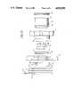
- FIG. 3is a side elevational view showing the portion of the endoscope handle of FIG. 1 on which its control wheels and braking mechanism are mounted.
- FIG. 4is a side elevational view showing the down/up braking mechanism mounted on the endoscope handle of FIG. 1.
- FIG. 5is an exploded elevational view of the control wheel and braking mechanism used in the inventive contamination protection system of FIG. 1.
- FIG. 6is a cross-sectional view of the removable control wheel and braking mechanism used in the inventive contamination protection system of FIG. 1 shown in its assembled condition.
- FIG. 7is an exploded cross-sectional view of the right/left brake assembly used in the control wheel and braking mechanism of FIGS. 5 and 6.
- FIG. 8is a cross-sectional view of an alternative embodiment of the portion of an endoscope handle on which an alternative embodiment of a removable control wheel and braking mechanism is mounted.
- FIG. 9is a cross-sectional view of an alternative embodiment of a removable control wheel and braking mechanism for use with the endoscope handle of FIG. 8.
- FIG. 10is a partial exploded cross-sectional view of the alternative embodiment of the removable control wheel and braking mechanism of FIG. 9 and the endoscope handle of FIG. 8.
- FIG. 11is a side elevational view of an endoscope using the inventive contamination protection system in which a splatter guard is placed between the control knobs of the endoscope.
- FIG. 12is a cross-sectional view taken along the line 12--12 of FIG. 11.
- the inventive endoscope 10, illustrated in FIG. 1,has the same appearance as a conventional endoscope.
- the endoscopeincludes a handle 12 having an eyepiece 14 and an elongated, flexible insertion tube 16.
- the insertion tube 16is inserted into a body cavity, and light emitting from the distal end of the insertion tube 16 illuminates tissues in the body cavity.
- the image viewed through the distal end of the insertion tube 16is conveyed to the endoscope handle 12, either through an internal fiberoptic bundle or electronically from a miniature television camera mounted at the distal end of the insertion tube 16.
- the imageis conveyed through the insertion tube 16 through a fiberoptic bundle and is visible through the eyepiece 14.
- the insertion tube 16also normally includes internal channels (not shown) opening at the distal end of the insertion tube 16. These tubes are used for suctioning fluids from the body cavity, for inserting air into the body cavity and for spraying water onto a lens (not shown) at the distal end of the insertion tube 16, in order to clean the lens.
- the suction through the suction channel of the insertion tube 16is controlled by a suction valve 30 while the flow of air and water through the air and water channels, respectively, is controlled by a combination air/water valve 32.
- the insertion tubeis manipulated in the up and down direction by rotating an up/down (“U/D") control wheel 40 in opposite directions and in the right and left directions by manipulating a right/left (“R/L”) control wheel 44.
- U/Dup/down
- R/Lright/left
- the control wheels 40, 44drive respective pulleys, each of which retract and pay out a pair of complementary control cables extending through the insertion tube 16 to its distal end.
- the control wheels 40, 44can be frictionally locked through respective, internal braking mechanisms, as also described in greater detail below.
- the inventive endoscope 10is most advantageously used with the protective endoscope sheath described in and claimed in U.S. Pat. No. 4,646,722.
- the handle 12except for the eyepiece 14, is surrounded by a protective bag 50 that prevents contamination of the handle 12.
- the bag 50preferably mates with a protective sheath 52 to prevent contamination of the endoscope 10 at the junction between the bag 50 and sheath 52.
- the bag 50 and sheath 52are installed on the endoscope by inserting the insertion tube 16 into the sheath 52 through an opening 54 in the bag 50.
- the control wheels 40, 44 and internal braking mechanism(not shown) are specially adapted to be removed from the handle 12 so that the control wheels 40, 44 may be mounted outside the bag 50.
- the opening 54is closed by suitable means such as by removing a backing strip 56 from a strip of adhesive applied to the bag so that opposite edges of the bag opening 54 adhere to each other.
- the control wheels 40, 44are then mounted on the handle 12, as illustrated in FIG. 1, thereby making the endoscope 10 ready for use.
- the fiber optic system as depicted in FIG. 1,shows an eyepiece 14 extending through insertion tube 16 allowing the endoscopist to view directly into the optical components. It is also possible to have the bag 50 cover the eyepiece 14 of the fiber optic system with a clear membrane to further isolate the endoscope handle 12.
- the primary reason for encouraging the designis to allow for quick and simple accessory attachment; such as cameras and teaching apparatus. It is also important to note that an endoscopist would not, under normal circumstances, touch the eyepiece 14 of his or her endoscope and hence a very low risk exists for cross contamination with this design. If one wishes to eliminate any possibility of cross contamination, an eyepiece cover must be used.
- control wheels 40, 44are removed from the handle 12 and sterilized in an autoclave.
- the handle 12is then removed from the bag 50 through the opening 54 after the edges of the opening 54 are pulled apart, and the insertion tube 16 is removed from the sheath 52.
- the only portions of the endoscope 10 that become contaminatedare the control wheels 40, 44.
- the control wheels 40, 44could be placed inside the bag 50 so that the wheels 40, 44 are manipulated through the bag 50.
- placing the control wheels 40, 44 inside the bag 50makes it very difficult to manipulate the control wheels 40, 44, particularly when they must be rotated in opposite directions.
- FIGS. 3-7The removable control wheels 40, 44, braking mechanisms and associated hardware are illustrated in FIGS. 3-7.
- a cylindrical housing 70is mounted within the handle 12 and encloses a first pulley 72 on which right/left control cables 74 are mounted and a second pulley 76 on which up/down control cables 78 are wound.
- the right/left control cables 74are connected to diametrically opposite portions of the insertion tube 16 at the distal ends to control the upward and downward movement of the distal end of the insertion tube 16 responsive to the rotation of the pulley 72 in opposite directions.
- the up/down control cables 78are connected to diametrically opposite portions of the distal end of the insertion tube 16 so that the distal end of the insertion tube 16 moves down and up responsive to rotation of the pulley 76 in opposite directions.
- a cylindrical, threaded, hollow stud 80projects outwardly from the housing 70.
- a first shaft 86extends through the stud 80 and is connected to the up/down pulley 76.
- a second shaft 88extends through the hollow axis of shaft 86 and is connected to the right/left pulley 72.
- a nonrotating mounting pin 90extends through the shafts 86, 88 and is anchored to a stationary portion of the housing 12.
- a notch 92 formed in the mounting pin 90allows the control mechanism to be fixedly secured to the housing 12 as explained in greater detail below.
- a up/down brakeincludes a brake actuator member 100 having an internally threaded cylindrical portion 102 terminating in an outwardly extending flange 104.
- the cylindrical portion 102is threaded onto the stud 80.
- An annular brake pad 106 of conventional materialis mounted on the upper surface of the flange 104.
- a stainless steel plate 108is retained on the up/down shaft 86 by a conventional retaining ring 110 received within an annular groove in the shaft 86.
- the shaft 86has an octagonal shape, and the inner periphery of the plate 108 is configured to match this octagonal shape. As a result, the plate 108 and shaft 86 rotate together.
- a plurality of circumferentially spaced notches 112are formed on the outer periphery of the flange 104.
- Rotation of the cylindrical portion 102 and flange 104causes the flange 104 to move inwardly and outwardly along the stud 80. Outward movement of the flange 104 forces the brake pads 106 against the brake plate to frictionally restrain rotational movement of the brake plate 108. Since the brake plate 108 is keyed to the shaft 86, rotation of the shaft 86 is restrained by the friction between the brake pads 106 and the brake plate 108. The magnitude of this frictional restraint is controlled by the rotational position of the cylindrical portion 102 and flange 104.
- a cylindrical brake coupling ring 120 having an outwardly projecting brake handle 122is secured to a brake coupling member 124 by a plurality of circumferentially spaced screws 126 (FIG. 6).
- the brake coupling member 124includes an outwardly projecting flange 128 that is captured by a retaining ring 130.
- the retaining ring 130is secured to a up/down control knob 134 by a plurality of circumferentially spaced screws 136.
- An annular spacer 138spaces the retaining ring 130 a slight distance from the flange 128 of the brake coupling member 124.
- the brake coupling member 124includes a plurality of cogs 140 projecting axially toward the handle 12. The cogs 140 are received by the respective notches 112 in the flange 104 of the brake actuator member 100 (FIG. 4).
- rotation of the brake handle 122rotates the brake actuator member 100 through the brake coupling member 124.
- rotation of the up/down control knob 134rotates the up/down shaft 86 (FIG. 4) since the internal bore of the up/down control knob 134 is keyed to the hexagonal shape of the shaft 86.
- the up/down control knob 134is rotatably secured to other components of the control wheel and brake mechanism through a mounting member 150 having an outwardly projecting flange 152 surrounding a cylindrical portion 154.
- the flange 152is secured to the outer face of the inner portion of the up/down control knob 134 by suitable means, such as a conventional adhesive.
- a ball bearing assembly 160having inner and outer races 162, 164, respectively, is mounted in the mounting member 150 by securing the outer surface of the outer race 164 to the inner surface of the cylindrical portion 154 of the mounting member 150.
- the inner surface of the inner race 162is secured around the outer surface of a cylindrical portion 170 of a second mounting member 172 by suitable means, such as a conventional adhesive.
- the mounting member 172includes an outwardly projecting flange 174 that is secured to a right/left control knob 176 by a plurality of circumferentially spaced screws 178.
- the right/left control knob 176is thus rotatably secured to the up/down control knob through the mounting member 150, ball bearing assembly 160 and mounting member 172.
- the right/left control knob 176includes an integrally formed inwardly depending cylindrical flange 180 that surrounds the ball bearing assembly 160.
- a square aperture formed at the center of the right-left control knob 176is key to the square shape of the right/left control shaft 88.
- a hexagonal aperture formed at the center of the up/down control knob 134is key to the hexagonal shape of the up/down control shaft 86 so that rotation of the up/down control knob 134 rotates the up/down pulley 76 through the up/down control shaft 86.
- a right/left brake assembly 190is mounted on top of the right/left control knob 176.
- the right/left brake assemblyis best illustrated in FIGS. 6 and 7.
- the right/left brake assemblyincludes a braking plate 200 having an inner surface 204, an outer surface 206, and a cylindrical boss 208.
- An annular brake pad 210 of frictional braking materialis secured to the inner surface 204 of the braking plate 200.
- the braking plate 200also includes outer, axially extending flange 212 having a plurality of circumferentially spaced notches formed on its inner surface, the purpose of which is explained below.
- the braking plate 200is keyed to the square mounting pin 90 so that the braking plate 200 cannot rotate.
- the boss 208 of the braking plate 200is externally threaded, and these threads mate with internal threads lining the border of a coupling member 222.
- the coupling member 222is, in turn, enclosed by a brake adjusting knob 230.
- a pair of radial recesses 236, 238are formed in the coupling member 222 at axially spaced locations.
- the recesses 236, 238receive respective compression springs 240, 242 which outwardly bias respective ball bearings 244, 246.
- Ball 246is biased against the inner surface of flange 212, which, it will be recalled, has formed therein a plurality of circumferentially spaced notches adapted to receive the ball 246.
- the ball 236is biased against the inner surface of a downwardly extending flange 250 forming part of the brake adjusting knob 230.
- the inner surface of the flange 250likewise has formed therein a plurality of circumferentially spaced grooves adapted to receive the ball 244.
- the spring constant of the spring 242is lower than the spring constant of the spring 240, the reason for which is explained below.
- the brake adjusting knob 230is rotatably secured to the coupling member 222 by an annular nut 260 having external threads 262 threaded into the internal threads of the coupling member 222.
- the nut 260is threaded into the coupling member 222 until a stepped shoulder 264 forcibly contacts the upper end of the coupling member 260.
- a second step shoulder 266 of the nut 260is spaced slightly from an inwardly stepped recess 268 of the brake adjustment knob 230 so that the brake adjustment knob 230 is free to rotate.
- the right/left braked assemblyis adjusted by rotating the brake adjustment knob 230.
- the rotation of the brake adjustment knob 230is then coupled to the coupling member 222 through the ball bearing 244 and notches formed on the interior surface of the flange 250 so that the coupling member 222 rotates with the brake adjustment knob 230.
- the spring 242has a lighter spring constant than the spring constant of the spring 240
- the ball bearing 246 mating with the notches formed in the flange 212 of the stationary braking plate 200does not prevent rotation of the coupling member 222. Instead, the ball bearing 246 and notches maintain the position of the coupling member 222 until a rotational force greater than a predetermined value is applied to the brake adjustment knob 230.
- Rotation of the coupling member 222applies a downward axial force to the braking plate 200 through the mating threads of the coupling member 222 and braking plate 200, thereby forcing the brake pad 210 against the upper surface of the up/down control knob 176 to increase the frictional braking force.
- the ball bearing 244 and notches formed in the flange 250are no longer capable of coupling the rotational force of the brake adjustment knob 220 to the coupling member 222, thereby allowing the brake adjustment knob 230 to rotate with respect to the coupling member 222.
- the spring 240 and ball bearing 244thus serve as a clutch to prevent excessive right/left brake adjustments.
- the right/left brake assembly 190is rotatably secured within the right/left control knob 176 by an annular ring 280 which is threaded into internal threads formed in the right/left control knob 176.
- the lower end 282 of the ringcontacts an outwardly extending peripheral flange 284 formed in the brake adjustment knob 230 to prevent axial movement of the brake adjustment knob 230, coupling member 222 and braking plate 200.
- the entire control and brake mechanism illustrated in FIG. 6is secured to the handle of the endoscope by a clip member 290 (FIG. 7) fitting onto a pair of studs 292 projecting from the brake adjustment knob 230.
- An internal elongated slot and recess formed in the clip member 290receives the end of the mounting pin 90 as the clip member 290 slides onto the studs 292.
- the clip member 290thus rotates with the brake adjustment knob 230 and, in cooperation with the notch 92 formed in the mounting pin 90, releasably secures the clamp and brake mechanism to the handle of the endoscope.
- FIGS. 8-10An alternative embodiment of a removable control and braking mechanism is illustrated in FIGS. 8-10.
- the portions of the mechanism fixedly mounted in the handle 12 of the endoscope 10is basically the same as in the embodiment of FIGS. 3-7.
- the major components of the embodiment of FIG. 8include concentric right/left and up/down control shafts 300, 302, a braking plate 304 retained in position on shaft 302 by a retaining ring 306 and an annular brake pad 308 of frictional braking material mounted on a brake actuating plate 310 and connected to a brake actuating member 312 so that the actuating plate 310 and actuating member 312 rotate as a unit.
- the brake actuating member 312is coupled to a removable portion of the control and braking mechanism in order to rotate the actuating member 312.
- the brake actuating plate 310is mounted on a threaded boss 314 so that rotation of the brake actuating plate unscrews the actuating plate 310 from the boss 314.
- rotation of the brake actuating member 312raises the brake actuating plate 310, thereby forcing the frictional braking material 308 against the plate 304.
- the plate 304is keyed to the control shaft 302 so that the friction between the material 308 and the plate 304 restricts rotation of the shaft 302.
- a stationary support shaft 314projects coaxially through the shafts 300, 302.
- the removable portions of the control and braking mechanismare mounted on the shaft 314.
- FIGS. 8-10differs from the embodiment of FIGS. 3-7 primarily in the manner in which the removable control and braking mechanism is releasably secured to the handle 12 of the endoscope 10.
- an end plate 320is secured to the end of the brake actuating knob 220 by a pair of screws 322.
- a release button 330is mounted in the end plate 320 at the end of an elongated release member 332.
- the release member 332is slidably mounted in a coupling shaft 334 having a pair of apertures 336 receiving respective ball bearings 338.
- a recessed portion 340 of the release member 332is positioned adjacent the ball bearings 338 when the release button 330 is pressed. When the recess portion 340 is adjacent the ball bearings 338, the ball bearings can move inwardly. At all other times, the ball bearings 338 are maintained in their outer position by the full diameter of the release member 332.
- the coupling shaft 334is inserted into the support shaft 314 after the release button 330 has been pressed to allow the locking balls 338 to move inwardly into the recess portion 340 of the release member 332.
- the release button 330is biased upwardly by a compression spring 342.
- the locking balls 338are positioned adjacent an annular groove 334 formed in the interior of the support shaft 314, the locking balls 338 are forced outwardly into the groove 334 by the upward movement of the release button 330.
- the release button 330is pressed, thereby allowing the locking balls 338 to move inwardly into the recess portion 340.
- the removable portion of the control and braking mechanismis then removed from the handle by sliding the coupling shaft 334 out of the support shaft 314.
- an endoscopistuses his or her right hand to advance and retract the endoscopest by manipulating the insertion tube 16 directly.
- the right handthen becomes contaminated from debris from the insertion tube 16.
- the same handwould more than likely be used to control the right/left control knob 44 of the endoscope, thereby causing direct contamination from the insertion tube debris.
- these contaminantscan be prevented from traveling further onto the endoscope hand piece 12, by using a guard 390 in the form of a thin circular plate between the up/down and the right/left control knob 44.
- the diameter of the guard 390should be substantially larger than the diameter of the right/left control knob 40 to prevent either the right/left control knob 40 from being manipulated by the right hand or the up/down control knob 44 from being manipulated by the left hand.
- the guard 390prevents the left hand of the endoscopist from manipulating the right/left control knob 44 or inadvertently contacting the right/left control knob 44.
- the guard 390would prevent the endoscopist's right hand from inadvertently contacting the up/down control knob 40 or manipulating the up/down control knob 40.
Landscapes
- Health & Medical Sciences (AREA)
- Life Sciences & Earth Sciences (AREA)
- Surgery (AREA)
- Biomedical Technology (AREA)
- Medical Informatics (AREA)
- Optics & Photonics (AREA)
- Pathology (AREA)
- Radiology & Medical Imaging (AREA)
- Biophysics (AREA)
- Engineering & Computer Science (AREA)
- Physics & Mathematics (AREA)
- Heart & Thoracic Surgery (AREA)
- Nuclear Medicine, Radiotherapy & Molecular Imaging (AREA)
- Molecular Biology (AREA)
- Animal Behavior & Ethology (AREA)
- General Health & Medical Sciences (AREA)
- Public Health (AREA)
- Veterinary Medicine (AREA)
- Endoscopes (AREA)
- Instruments For Viewing The Inside Of Hollow Bodies (AREA)
Abstract
Description
Claims (18)
Priority Applications (4)
| Application Number | Priority Date | Filing Date | Title |
|---|---|---|---|
| US07/193,833US4825850A (en) | 1988-05-13 | 1988-05-13 | Contamination protection system for endoscope control handles |
| CA000599154ACA1305900C (en) | 1988-05-13 | 1989-05-09 | Contamination protection system for endoscope control handles |
| EP89108504AEP0341719A1 (en) | 1988-05-13 | 1989-05-11 | Contamination protection system for endoscope control handles |
| JP1121295AJP2746651B2 (en) | 1988-05-13 | 1989-05-15 | Pollution control device for control handle of endoscope |
Applications Claiming Priority (1)
| Application Number | Priority Date | Filing Date | Title |
|---|---|---|---|
| US07/193,833US4825850A (en) | 1988-05-13 | 1988-05-13 | Contamination protection system for endoscope control handles |
Publications (1)
| Publication Number | Publication Date |
|---|---|
| US4825850Atrue US4825850A (en) | 1989-05-02 |
Family
ID=22715203
Family Applications (1)
| Application Number | Title | Priority Date | Filing Date |
|---|---|---|---|
| US07/193,833Expired - LifetimeUS4825850A (en) | 1988-05-13 | 1988-05-13 | Contamination protection system for endoscope control handles |
Country Status (4)
| Country | Link |
|---|---|
| US (1) | US4825850A (en) |
| EP (1) | EP0341719A1 (en) |
| JP (1) | JP2746651B2 (en) |
| CA (1) | CA1305900C (en) |
Cited By (121)
| Publication number | Priority date | Publication date | Assignee | Title |
|---|---|---|---|---|
| US4979497A (en)* | 1989-06-06 | 1990-12-25 | Olympus Optical Co., Ltd. | Endoscope |
| US5168863A (en)* | 1990-08-27 | 1992-12-08 | Medical Concepts, Inc. | Sterile endoscopic system |
| US5201908A (en)* | 1991-06-10 | 1993-04-13 | Endomedical Technologies, Inc. | Sheath for protecting endoscope from contamination |
| US5237984A (en)* | 1991-06-24 | 1993-08-24 | Xomed-Treace Inc. | Sheath for endoscope |
| US5301656A (en)* | 1991-04-19 | 1994-04-12 | Olympus Optical Co., Ltd. | Endoscope |
| DE4238977A1 (en)* | 1992-11-19 | 1994-05-26 | Schoelly Fiberoptic Gmbh | Illumination and visual inspection device for cavities and interstices - comprises reusable optical system holder and disposable tubular lighting unit into which it is snap-fitted |
| WO1994011771A1 (en)* | 1992-11-06 | 1994-05-26 | Clarus Medical Systems, Inc. | Surgical instrument with stick-on fiber-optic viewing system |
| US5329887A (en)* | 1992-04-03 | 1994-07-19 | Vision Sciences, Incorporated | Endoscope control assembly with removable control knob/brake assembly |
| US5335663A (en)* | 1992-12-11 | 1994-08-09 | Tetrad Corporation | Laparoscopic probes and probe sheaths useful in ultrasonic imaging applications |
| US5359991A (en)* | 1991-04-24 | 1994-11-01 | Asahi Kogaku Kogyo Kabushiki Kaisha | Cover device for endoscope |
| US5386817A (en)* | 1991-06-10 | 1995-02-07 | Endomedical Technologies, Inc. | Endoscope sheath and valve system |
| US5413573A (en)* | 1991-05-24 | 1995-05-09 | Onesys Oy | Device for surgical procedures |
| US5419310A (en)* | 1992-11-03 | 1995-05-30 | Vision Sciences, Inc. | Partially inflated protective endoscope sheath |
| US5429118A (en)* | 1994-04-07 | 1995-07-04 | Cook (Canada) Incorporated | Disposable medical scope sheath |
| US5447148A (en)* | 1993-07-08 | 1995-09-05 | Vision Sciences, Inc. | Endoscopic contamination protection system to facilitate cleaning of endoscopes |
| US5458132A (en)* | 1993-03-15 | 1995-10-17 | Olympus Optical Co., Ltd. | Endoscope cover-sheathed endoscope system |
| US5458133A (en)* | 1993-03-15 | 1995-10-17 | Olympus Optical Co., Ltd. | Cover type endoscope apparatus |
| US5460166A (en)* | 1993-03-11 | 1995-10-24 | Olympus Optical, Ltd. | Endoscope of an endoscope cover system wherein, at the time of the maximum curvature, a fluid tube path will be curved as twisted so as to move to the side on which the radius of curvature will become larger |
| US5460167A (en)* | 1993-03-04 | 1995-10-24 | Olympus Optical Co., Ltd. | Endoscope cover with channel |
| US5464007A (en)* | 1994-02-23 | 1995-11-07 | Welch Allyn, Inc. | Fluid insensitive braking for an endoscope |
| US5487376A (en)* | 1993-02-25 | 1996-01-30 | Olympus Optical Co., Ltd. | Washing apparatus for a protection cover for an endoscope |
| US5503616A (en)* | 1991-06-10 | 1996-04-02 | Endomedical Technologies, Inc. | Collapsible access channel system |
| US5514074A (en)* | 1993-02-12 | 1996-05-07 | Olympus Optical Co., Ltd. | Endoscope apparatus of an endoscope cover system for preventing buckling of an endoscope cover |
| US5526928A (en)* | 1993-01-22 | 1996-06-18 | Olympus Optical Co., Ltd. | Package for packaging a protection cover with channel for endoscope |
| US5536235A (en)* | 1993-02-09 | 1996-07-16 | Olympus Optical Co., Ltd. | Endoscope apparatus of endoscope cover type |
| US5536236A (en)* | 1993-02-12 | 1996-07-16 | Olympus Optical Co., Ltd. | Covered endoscope system |
| US5538496A (en)* | 1993-02-01 | 1996-07-23 | Olympus Optical Co., Ltd. | Endoscope cover type endoscope |
| US5545121A (en)* | 1993-02-02 | 1996-08-13 | Olympus Optical Co., Ltd. | Cover-type endoscope apparatus |
| US5551945A (en)* | 1993-03-16 | 1996-09-03 | Olympus Optical Co., Ltd. | Endoscope system including endoscope and protection cover |
| US5554098A (en)* | 1993-02-26 | 1996-09-10 | Olympus Optical Co., Ltd. | Endoscope system including endoscope and disposable protection cover |
| US5562602A (en)* | 1993-03-15 | 1996-10-08 | Olympus Optical Co., Ltd. | Insert cover portion of endoscope cover, insert cover portion having channels of endoscope cover, endoscope-cover-type endoscope, endoscope-cover-system endoscope and endoscope apparatus |
| US5575753A (en)* | 1993-03-05 | 1996-11-19 | Olympus Optical Co., Ltd. | Endoscopic apparatus using a covered type endoscope fitted in an endoscope cover |
| US5575752A (en)* | 1993-02-19 | 1996-11-19 | Olympus Optical Co., Ltd. | Endoscope system, cover type endoscope unit, channeled cover type endoscope unit, holding tool in endoscope system, and housing member of cover type endoscope unit |
| US5575755A (en)* | 1994-02-23 | 1996-11-19 | Welch Allyn, Inc. | Fluid insensitive braking for an endoscope |
| US5626553A (en)* | 1995-06-05 | 1997-05-06 | Vision-Sciences, Inc. | Endoscope articulation system to reduce effort during articulation of an endoscope |
| US5630787A (en)* | 1993-02-18 | 1997-05-20 | Olympus Optical Co., Ltd. | System including endoscope and disposable protection cover with channel |
| EP0754429A3 (en)* | 1995-06-07 | 1997-06-11 | Advanced Tech Lab | Ultrasonic endoscopic probe |
| US5674182A (en)* | 1993-02-26 | 1997-10-07 | Olympus Optical Co., Ltd. | Endoscope system including endoscope and protection cover |
| US5674180A (en)* | 1993-03-15 | 1997-10-07 | Olympus Optical Co., Ltd. | Endoscope system including endoscope and disposable protection cover |
| US5688221A (en)* | 1993-02-12 | 1997-11-18 | Olympus Optical Co., Ltd. | Endoscope cover for endoscope system having uniform flexibility |
| US5695449A (en)* | 1995-04-18 | 1997-12-09 | Olympus Optical Co., Ltd. | Cover-sheathed endoscope |
| US5695450A (en)* | 1993-03-05 | 1997-12-09 | Olympus Optical Co., Ltd. | Cover-type endoscope apparatus |
| US5695491A (en)* | 1994-11-22 | 1997-12-09 | Washington Research Foundation | Endoscopic accessory and containment system |
| US5695447A (en)* | 1993-03-16 | 1997-12-09 | Olympus Optical Company, Ltd. | Endoscope system including endoscope and disposable protection cover |
| US5697887A (en)* | 1993-02-23 | 1997-12-16 | Olympus Optical Co., Ltd. | Endoscope cover apparatus for use with cover-type endoscope and endoscope cover holding apparatus |
| US5733243A (en)* | 1993-02-12 | 1998-03-31 | Olympus Optical Co., Ltd. | Endoscope apparatus of an endoscope cover system for preventing buckling of an endoscope cover |
| US5863286A (en)* | 1993-01-27 | 1999-01-26 | Olympus Optical Company, Ltd. | Endoscope system including endoscope and disposable protection cover |
| US20030097043A1 (en)* | 2001-11-01 | 2003-05-22 | Pentax Corporation | Cover for preventing contamination of an operating portion of an endoscope |
| US20050181327A1 (en)* | 2004-02-13 | 2005-08-18 | Jack Graham | Disposable protective sleeve for temporarily covering hand-held dental light curing guns |
| US20060149127A1 (en)* | 2004-12-30 | 2006-07-06 | Seddiqui Fred R | Disposable multi-lumen catheter with reusable stylet |
| US20060167343A1 (en)* | 2002-10-11 | 2006-07-27 | Michael Peszynski | Control mechanism for an endoscope |
| US20060229495A1 (en)* | 2005-04-08 | 2006-10-12 | Frith Martin A | Rotatable coupler for endoscopic camera |
| US20070015989A1 (en)* | 2005-07-01 | 2007-01-18 | Avantis Medical Systems, Inc. | Endoscope Image Recognition System and Method |
| US20070142711A1 (en)* | 2005-12-13 | 2007-06-21 | Lex Bayer | Detachable Imaging Device, Endoscope Having A Detachable Imaging Device, And Method of Configuring Such An Endoscope |
| US20070177009A1 (en)* | 2005-01-05 | 2007-08-02 | Avantis Medical Systems, Inc. | Endoscope assembly with a polarizing filter |
| US20070244354A1 (en)* | 2006-04-18 | 2007-10-18 | Avantis Medical Systems, Inc. | Vibratory Device, Endoscope Having Such A Device, Method For Configuring An Endoscope, And Method Of Reducing Looping Of An Endoscope. |
| US20070270642A1 (en)* | 2006-05-19 | 2007-11-22 | Avantis Medical Systems, Inc. | System and method for producing and improving images |
| US20070287887A1 (en)* | 2006-06-08 | 2007-12-13 | Pentax Corporation | Bendable portion control mechanism of an endoscope |
| US20070293720A1 (en)* | 2005-01-05 | 2007-12-20 | Avantis Medical Systems, Inc. | Endoscope assembly and method of viewing an area inside a cavity |
| US20080021274A1 (en)* | 2005-01-05 | 2008-01-24 | Avantis Medical Systems, Inc. | Endoscopic medical device with locking mechanism and method |
| US20080033450A1 (en)* | 2006-08-04 | 2008-02-07 | Lex Bayer | Surgical Port With Embedded Imaging Device |
| US20080109020A1 (en)* | 1999-11-16 | 2008-05-08 | Deka Products Limited Partnership | Endoscopic Tissue Separator Surgical Device |
| US20080208001A1 (en)* | 2007-02-26 | 2008-08-28 | Ron Hadani | Conforming endoscope |
| US20080228038A1 (en)* | 2005-04-01 | 2008-09-18 | Welch Allyn, Inc. | Illumination Assembly For Use With Vaginal Speculum Apparatus |
| US20080253686A1 (en)* | 2007-04-10 | 2008-10-16 | Avantis Medical Systems, Inc. | Method and Device for Examining or Imaging an Interior Surface of a Cavity |
| US20080319263A1 (en)* | 2007-06-22 | 2008-12-25 | Hoya Corporation | Rotation mechanism for endoscope |
| US20090225159A1 (en)* | 2008-03-07 | 2009-09-10 | Scott Schneider | Visual inspection device |
| US20090231419A1 (en)* | 2007-02-06 | 2009-09-17 | Avantis Medical Systems, Inc. | Endoscope Assembly and Method of Performing a Medical Procedure |
| US20090287192A1 (en)* | 2005-04-01 | 2009-11-19 | Vivenzio Robert L | Medical diagnostic instrument having portable illuminator |
| US8142352B2 (en) | 2006-04-03 | 2012-03-27 | Welch Allyn, Inc. | Vaginal speculum assembly having portable illuminator |
| US8235887B2 (en) | 2006-01-23 | 2012-08-07 | Avantis Medical Systems, Inc. | Endoscope assembly with retroscope |
| US8289381B2 (en) | 2005-01-05 | 2012-10-16 | Avantis Medical Systems, Inc. | Endoscope with an imaging catheter assembly and method of configuring an endoscope |
| CN102813498A (en)* | 2012-09-10 | 2012-12-12 | 华东理工大学 | Endoscopic bending angle control handle controlled by one hand |
| CN103654695A (en)* | 2013-12-24 | 2014-03-26 | 深圳市开立科技有限公司 | Endoscope curve operation part and endoscope |
| US8797392B2 (en) | 2005-01-05 | 2014-08-05 | Avantis Medical Sytems, Inc. | Endoscope assembly with a polarizing filter |
| WO2014186519A3 (en)* | 2013-05-17 | 2015-01-08 | Endochoice, Inc. | Endoscope control unit with braking system |
| USD731652S1 (en) | 2014-02-19 | 2015-06-09 | Tidi Products, Llc | Dental curing light sleeve |
| US20150196363A1 (en)* | 2013-12-07 | 2015-07-16 | Insurgical Inc. | Limited-use tool disposable enclosure |
| WO2015120348A1 (en) | 2014-02-06 | 2015-08-13 | Dentsply International Inc. | Inspection of dental roots and the endodontic cavity space therein |
| US9433468B2 (en) | 2013-10-04 | 2016-09-06 | Tidi Products, Llc | Sheath for a medical or dental instrument |
| US9474440B2 (en) | 2009-06-18 | 2016-10-25 | Endochoice, Inc. | Endoscope tip position visual indicator and heat management system |
| US9532706B2 (en) | 2014-08-07 | 2017-01-03 | Welch Allyn, Inc. | Vaginal speculum with illuminator |
| US9667935B2 (en) | 2013-05-07 | 2017-05-30 | Endochoice, Inc. | White balance enclosure for use with a multi-viewing elements endoscope |
| US9706908B2 (en) | 2010-10-28 | 2017-07-18 | Endochoice, Inc. | Image capture and video processing systems and methods for multiple viewing element endoscopes |
| US9943218B2 (en) | 2013-10-01 | 2018-04-17 | Endochoice, Inc. | Endoscope having a supply cable attached thereto |
| US9949623B2 (en) | 2013-05-17 | 2018-04-24 | Endochoice, Inc. | Endoscope control unit with braking system |
| US9968242B2 (en) | 2013-12-18 | 2018-05-15 | Endochoice, Inc. | Suction control unit for an endoscope having two working channels |
| US10064541B2 (en) | 2013-08-12 | 2018-09-04 | Endochoice, Inc. | Endoscope connector cover detection and warning system |
| US10078207B2 (en) | 2015-03-18 | 2018-09-18 | Endochoice, Inc. | Systems and methods for image magnification using relative movement between an image sensor and a lens assembly |
| US10105039B2 (en) | 2013-06-28 | 2018-10-23 | Endochoice, Inc. | Multi-jet distributor for an endoscope |
| US10123684B2 (en) | 2014-12-18 | 2018-11-13 | Endochoice, Inc. | System and method for processing video images generated by a multiple viewing elements endoscope |
| US10130246B2 (en) | 2009-06-18 | 2018-11-20 | Endochoice, Inc. | Systems and methods for regulating temperature and illumination intensity at the distal tip of an endoscope |
| US10258222B2 (en) | 2014-07-21 | 2019-04-16 | Endochoice, Inc. | Multi-focal, multi-camera endoscope systems |
| US10271713B2 (en) | 2015-01-05 | 2019-04-30 | Endochoice, Inc. | Tubed manifold of a multiple viewing elements endoscope |
| US10292570B2 (en) | 2016-03-14 | 2019-05-21 | Endochoice, Inc. | System and method for guiding and tracking a region of interest using an endoscope |
| CN109770830A (en)* | 2019-01-29 | 2019-05-21 | 深圳市先赞科技有限公司 | For the rotary buckle mechanism inside endoscope handle |
| US10376181B2 (en) | 2015-02-17 | 2019-08-13 | Endochoice, Inc. | System for detecting the location of an endoscopic device during a medical procedure |
| US10401611B2 (en) | 2015-04-27 | 2019-09-03 | Endochoice, Inc. | Endoscope with integrated measurement of distance to objects of interest |
| US10488648B2 (en) | 2016-02-24 | 2019-11-26 | Endochoice, Inc. | Circuit board assembly for a multiple viewing element endoscope using CMOS sensors |
| US10516865B2 (en) | 2015-05-17 | 2019-12-24 | Endochoice, Inc. | Endoscopic image enhancement using contrast limited adaptive histogram equalization (CLAHE) implemented in a processor |
| US10517464B2 (en) | 2011-02-07 | 2019-12-31 | Endochoice, Inc. | Multi-element cover for a multi-camera endoscope |
| US10524645B2 (en) | 2009-06-18 | 2020-01-07 | Endochoice, Inc. | Method and system for eliminating image motion blur in a multiple viewing elements endoscope |
| US10542877B2 (en) | 2014-08-29 | 2020-01-28 | Endochoice, Inc. | Systems and methods for varying stiffness of an endoscopic insertion tube |
| US10588495B2 (en) | 2016-07-28 | 2020-03-17 | Cook Medical Technologies LL | Brake mechanism of a steerable catheter |
| US10595714B2 (en) | 2013-03-28 | 2020-03-24 | Endochoice, Inc. | Multi-jet controller for an endoscope |
| US10663714B2 (en) | 2010-10-28 | 2020-05-26 | Endochoice, Inc. | Optical system for an endoscope |
| US10709317B2 (en) | 2018-10-04 | 2020-07-14 | PraesidioDyne, LLC | Clamp assembly for disposable endoscopic sheaths |
| US10898062B2 (en) | 2015-11-24 | 2021-01-26 | Endochoice, Inc. | Disposable air/water and suction valves for an endoscope |
| WO2021063966A1 (en)* | 2019-10-03 | 2021-04-08 | Carlo Alberto Bosi | Endoscopy device with orientable head |
| US10993605B2 (en) | 2016-06-21 | 2021-05-04 | Endochoice, Inc. | Endoscope system with multiple connection interfaces to interface with different video data signal sources |
| US11082598B2 (en) | 2014-01-22 | 2021-08-03 | Endochoice, Inc. | Image capture and video processing systems and methods for multiple viewing element endoscopes |
| US11234581B2 (en) | 2014-05-02 | 2022-02-01 | Endochoice, Inc. | Elevator for directing medical tool |
| US11364022B2 (en) | 2018-05-08 | 2022-06-21 | Ithemba, LLC | Reusable core needle biopsy device and disposable needle system to eliminate internal contamination risk in reusable portion of device |
| US11529197B2 (en) | 2015-10-28 | 2022-12-20 | Endochoice, Inc. | Device and method for tracking the position of an endoscope within a patient's body |
| CN115551403A (en)* | 2020-05-08 | 2022-12-30 | 富士胶片株式会社 | Forceps for endoscopes |
| USD975275S1 (en)* | 2019-08-15 | 2023-01-10 | Auris Health, Inc. | Handle for a medical instrument |
| CN116115163A (en)* | 2023-01-28 | 2023-05-16 | 中日友好医院(中日友好临床医学研究所) | Hard mirror components and endoscopic equipment |
| US11786112B2 (en) | 2020-04-30 | 2023-10-17 | Ambu A/S | Endoscope control system |
| US12050313B2 (en)* | 2018-10-01 | 2024-07-30 | Olympus Corporation | Operation member fixing mechanism and endoscope |
| US12207796B2 (en) | 2013-03-28 | 2025-01-28 | Endochoice Inc. | Multi-jet controller for an endoscope |
| EP4382023A4 (en)* | 2021-12-07 | 2025-06-25 | Guangzhou Red Pine Medical Instrument Co., Ltd. | ENDOSCOPE |
Families Citing this family (6)
| Publication number | Priority date | Publication date | Assignee | Title |
|---|---|---|---|---|
| US5556367A (en)* | 1993-03-05 | 1996-09-17 | Olympus Optical Co., Ltd. | Cover type endoscope apparatus |
| JP4617059B2 (en) | 2001-04-20 | 2011-01-19 | パワー メディカル インターベンションズ, エルエルシー | Imaging device |
| EP1478263B1 (en) | 2002-01-30 | 2011-03-09 | Tyco Healthcare Group LP | Surgical imaging device |
| AU2003275336A1 (en) | 2002-09-30 | 2004-04-23 | Power Medical Interventions, Inc. | Self-contained sterilizable surgical system |
| US12004717B2 (en) | 2019-12-20 | 2024-06-11 | Gyrus Acmi, Inc. | Endoscope with detachable camera module |
| US12004708B2 (en) | 2020-04-30 | 2024-06-11 | Gyrus Acmi, Inc. | Insertion sheath for modular disposable endoscope components |
Citations (7)
| Publication number | Priority date | Publication date | Assignee | Title |
|---|---|---|---|---|
| US3426749A (en)* | 1965-05-20 | 1969-02-11 | Longworth Scient Instr Co Ltd | Disposable cover for laryngoscope blade |
| US3794091A (en)* | 1971-10-07 | 1974-02-26 | Med General Inc | Sterile sheath for surgical illuminator |
| US3809072A (en)* | 1971-10-07 | 1974-05-07 | Med General Inc | Sterile sheath apparatus for fiber optic illuminator with compatible lens |
| US4461282A (en)* | 1978-05-02 | 1984-07-24 | Kabushiki Kaisha Medos Kenkyusho | Mechanism for direction changing of endoscope top end |
| US4646722A (en)* | 1984-12-10 | 1987-03-03 | Opielab, Inc. | Protective endoscope sheath and method of installing same |
| US4741326A (en)* | 1986-10-01 | 1988-05-03 | Fujinon, Inc. | Endoscope disposable sheath |
| US4742816A (en)* | 1986-05-02 | 1988-05-10 | Olympus Optical Co., Ltd. | Operation device for endoscopes |
Family Cites Families (6)
| Publication number | Priority date | Publication date | Assignee | Title |
|---|---|---|---|---|
| JPS5720729A (en)* | 1980-07-14 | 1982-02-03 | Olympus Optical Co Ltd | Protection case for endoscope photographing apparatus |
| JPS58157432A (en)* | 1982-03-15 | 1983-09-19 | オリンパス光学工業株式会社 | Ultrasonic diagnostic apparatus of body cavity |
| JPS5982839A (en)* | 1982-09-24 | 1984-05-14 | アドバンスト・テクノロジ−・ラボラトリ−ズ・インコ−ポレイテツド | Antiseptic sheath instrument for ultrasonic scanning of internal operation |
| JPS61109552A (en)* | 1984-11-02 | 1986-05-28 | 株式会社東芝 | Ultrasonic probe with ultrasonic medium |
| JPS6368306U (en)* | 1986-10-25 | 1988-05-09 | ||
| US4721097A (en)* | 1986-10-31 | 1988-01-26 | Circon Corporation | Endoscope sheaths and method and apparatus for installation and removal |
- 1988
- 1988-05-13USUS07/193,833patent/US4825850A/ennot_activeExpired - Lifetime
- 1989
- 1989-05-09CACA000599154Apatent/CA1305900C/ennot_activeExpired - Lifetime
- 1989-05-11EPEP89108504Apatent/EP0341719A1/ennot_activeCeased
- 1989-05-15JPJP1121295Apatent/JP2746651B2/ennot_activeExpired - Fee Related
Patent Citations (7)
| Publication number | Priority date | Publication date | Assignee | Title |
|---|---|---|---|---|
| US3426749A (en)* | 1965-05-20 | 1969-02-11 | Longworth Scient Instr Co Ltd | Disposable cover for laryngoscope blade |
| US3794091A (en)* | 1971-10-07 | 1974-02-26 | Med General Inc | Sterile sheath for surgical illuminator |
| US3809072A (en)* | 1971-10-07 | 1974-05-07 | Med General Inc | Sterile sheath apparatus for fiber optic illuminator with compatible lens |
| US4461282A (en)* | 1978-05-02 | 1984-07-24 | Kabushiki Kaisha Medos Kenkyusho | Mechanism for direction changing of endoscope top end |
| US4646722A (en)* | 1984-12-10 | 1987-03-03 | Opielab, Inc. | Protective endoscope sheath and method of installing same |
| US4742816A (en)* | 1986-05-02 | 1988-05-10 | Olympus Optical Co., Ltd. | Operation device for endoscopes |
| US4741326A (en)* | 1986-10-01 | 1988-05-03 | Fujinon, Inc. | Endoscope disposable sheath |
Cited By (216)
| Publication number | Priority date | Publication date | Assignee | Title |
|---|---|---|---|---|
| US4979497A (en)* | 1989-06-06 | 1990-12-25 | Olympus Optical Co., Ltd. | Endoscope |
| US5168863A (en)* | 1990-08-27 | 1992-12-08 | Medical Concepts, Inc. | Sterile endoscopic system |
| US5301656A (en)* | 1991-04-19 | 1994-04-12 | Olympus Optical Co., Ltd. | Endoscope |
| US5359991A (en)* | 1991-04-24 | 1994-11-01 | Asahi Kogaku Kogyo Kabushiki Kaisha | Cover device for endoscope |
| US5413573A (en)* | 1991-05-24 | 1995-05-09 | Onesys Oy | Device for surgical procedures |
| US5386817A (en)* | 1991-06-10 | 1995-02-07 | Endomedical Technologies, Inc. | Endoscope sheath and valve system |
| US5503616A (en)* | 1991-06-10 | 1996-04-02 | Endomedical Technologies, Inc. | Collapsible access channel system |
| US5201908A (en)* | 1991-06-10 | 1993-04-13 | Endomedical Technologies, Inc. | Sheath for protecting endoscope from contamination |
| US5237984A (en)* | 1991-06-24 | 1993-08-24 | Xomed-Treace Inc. | Sheath for endoscope |
| US5413092A (en)* | 1991-06-24 | 1995-05-09 | Xomed-Treace, Inc. | Sheath for endoscope |
| EP0520743B1 (en)* | 1991-06-24 | 1997-01-29 | Xomed-Treace, Inc. | Sheath for endoscope |
| US5329887A (en)* | 1992-04-03 | 1994-07-19 | Vision Sciences, Incorporated | Endoscope control assembly with removable control knob/brake assembly |
| US5419310A (en)* | 1992-11-03 | 1995-05-30 | Vision Sciences, Inc. | Partially inflated protective endoscope sheath |
| WO1994011771A1 (en)* | 1992-11-06 | 1994-05-26 | Clarus Medical Systems, Inc. | Surgical instrument with stick-on fiber-optic viewing system |
| DE4238977A1 (en)* | 1992-11-19 | 1994-05-26 | Schoelly Fiberoptic Gmbh | Illumination and visual inspection device for cavities and interstices - comprises reusable optical system holder and disposable tubular lighting unit into which it is snap-fitted |
| US5335663A (en)* | 1992-12-11 | 1994-08-09 | Tetrad Corporation | Laparoscopic probes and probe sheaths useful in ultrasonic imaging applications |
| US5526928A (en)* | 1993-01-22 | 1996-06-18 | Olympus Optical Co., Ltd. | Package for packaging a protection cover with channel for endoscope |
| US5863286A (en)* | 1993-01-27 | 1999-01-26 | Olympus Optical Company, Ltd. | Endoscope system including endoscope and disposable protection cover |
| US5538496A (en)* | 1993-02-01 | 1996-07-23 | Olympus Optical Co., Ltd. | Endoscope cover type endoscope |
| US5545121A (en)* | 1993-02-02 | 1996-08-13 | Olympus Optical Co., Ltd. | Cover-type endoscope apparatus |
| US5536235A (en)* | 1993-02-09 | 1996-07-16 | Olympus Optical Co., Ltd. | Endoscope apparatus of endoscope cover type |
| US5688221A (en)* | 1993-02-12 | 1997-11-18 | Olympus Optical Co., Ltd. | Endoscope cover for endoscope system having uniform flexibility |
| US5514074A (en)* | 1993-02-12 | 1996-05-07 | Olympus Optical Co., Ltd. | Endoscope apparatus of an endoscope cover system for preventing buckling of an endoscope cover |
| US5733243A (en)* | 1993-02-12 | 1998-03-31 | Olympus Optical Co., Ltd. | Endoscope apparatus of an endoscope cover system for preventing buckling of an endoscope cover |
| US5536236A (en)* | 1993-02-12 | 1996-07-16 | Olympus Optical Co., Ltd. | Covered endoscope system |
| US5630787A (en)* | 1993-02-18 | 1997-05-20 | Olympus Optical Co., Ltd. | System including endoscope and disposable protection cover with channel |
| US5575752A (en)* | 1993-02-19 | 1996-11-19 | Olympus Optical Co., Ltd. | Endoscope system, cover type endoscope unit, channeled cover type endoscope unit, holding tool in endoscope system, and housing member of cover type endoscope unit |
| US5697887A (en)* | 1993-02-23 | 1997-12-16 | Olympus Optical Co., Ltd. | Endoscope cover apparatus for use with cover-type endoscope and endoscope cover holding apparatus |
| US5487376A (en)* | 1993-02-25 | 1996-01-30 | Olympus Optical Co., Ltd. | Washing apparatus for a protection cover for an endoscope |
| US5738630A (en)* | 1993-02-26 | 1998-04-14 | Olympus Optical Co., Ltd. | Endoscope system including endoscope and protection cover |
| US5554098A (en)* | 1993-02-26 | 1996-09-10 | Olympus Optical Co., Ltd. | Endoscope system including endoscope and disposable protection cover |
| US5779625A (en)* | 1993-02-26 | 1998-07-14 | Olympus Optical Co., Ltd. | Endoscope system including endoscope and protection cover |
| US5924977A (en)* | 1993-02-26 | 1999-07-20 | Olympus Optical Co., Ltd. | Endoscope system including endoscope and disposable protection cover |
| US5674182A (en)* | 1993-02-26 | 1997-10-07 | Olympus Optical Co., Ltd. | Endoscope system including endoscope and protection cover |
| US5460167A (en)* | 1993-03-04 | 1995-10-24 | Olympus Optical Co., Ltd. | Endoscope cover with channel |
| US5575753A (en)* | 1993-03-05 | 1996-11-19 | Olympus Optical Co., Ltd. | Endoscopic apparatus using a covered type endoscope fitted in an endoscope cover |
| US5695450A (en)* | 1993-03-05 | 1997-12-09 | Olympus Optical Co., Ltd. | Cover-type endoscope apparatus |
| US5460166A (en)* | 1993-03-11 | 1995-10-24 | Olympus Optical, Ltd. | Endoscope of an endoscope cover system wherein, at the time of the maximum curvature, a fluid tube path will be curved as twisted so as to move to the side on which the radius of curvature will become larger |
| US5562602A (en)* | 1993-03-15 | 1996-10-08 | Olympus Optical Co., Ltd. | Insert cover portion of endoscope cover, insert cover portion having channels of endoscope cover, endoscope-cover-type endoscope, endoscope-cover-system endoscope and endoscope apparatus |
| US5458132A (en)* | 1993-03-15 | 1995-10-17 | Olympus Optical Co., Ltd. | Endoscope cover-sheathed endoscope system |
| US5458133A (en)* | 1993-03-15 | 1995-10-17 | Olympus Optical Co., Ltd. | Cover type endoscope apparatus |
| US5674180A (en)* | 1993-03-15 | 1997-10-07 | Olympus Optical Co., Ltd. | Endoscope system including endoscope and disposable protection cover |
| US5695447A (en)* | 1993-03-16 | 1997-12-09 | Olympus Optical Company, Ltd. | Endoscope system including endoscope and disposable protection cover |
| US5993380A (en)* | 1993-03-16 | 1999-11-30 | Olympus Optical Co., Ltd. | Endoscope system including endoscope and protection cover |
| US5551945A (en)* | 1993-03-16 | 1996-09-03 | Olympus Optical Co., Ltd. | Endoscope system including endoscope and protection cover |
| US5447148A (en)* | 1993-07-08 | 1995-09-05 | Vision Sciences, Inc. | Endoscopic contamination protection system to facilitate cleaning of endoscopes |
| US5518501A (en)* | 1993-07-08 | 1996-05-21 | Vision-Sciences, Inc. | Endoscopic contamination protection system to facilitate cleaning of endoscopes |
| US5575755A (en)* | 1994-02-23 | 1996-11-19 | Welch Allyn, Inc. | Fluid insensitive braking for an endoscope |
| US5464007A (en)* | 1994-02-23 | 1995-11-07 | Welch Allyn, Inc. | Fluid insensitive braking for an endoscope |
| US5429118A (en)* | 1994-04-07 | 1995-07-04 | Cook (Canada) Incorporated | Disposable medical scope sheath |
| US5695491A (en)* | 1994-11-22 | 1997-12-09 | Washington Research Foundation | Endoscopic accessory and containment system |
| US5931833A (en)* | 1994-11-22 | 1999-08-03 | Silverstein; Fred E. | Endoscopic accessory and containment system |
| US5695449A (en)* | 1995-04-18 | 1997-12-09 | Olympus Optical Co., Ltd. | Cover-sheathed endoscope |
| US5626553A (en)* | 1995-06-05 | 1997-05-06 | Vision-Sciences, Inc. | Endoscope articulation system to reduce effort during articulation of an endoscope |
| US5667476A (en)* | 1995-06-05 | 1997-09-16 | Vision-Sciences, Inc. | Endoscope articulation system to reduce effort during articulation of an endoscope |
| EP0754429A3 (en)* | 1995-06-07 | 1997-06-11 | Advanced Tech Lab | Ultrasonic endoscopic probe |
| US20080109020A1 (en)* | 1999-11-16 | 2008-05-08 | Deka Products Limited Partnership | Endoscopic Tissue Separator Surgical Device |
| US20030097043A1 (en)* | 2001-11-01 | 2003-05-22 | Pentax Corporation | Cover for preventing contamination of an operating portion of an endoscope |
| US6852077B2 (en) | 2001-11-01 | 2005-02-08 | Pentax Corporation | Cover for preventing contamination of an operating portion of an endoscope |
| US7588536B2 (en)* | 2002-10-11 | 2009-09-15 | Koninklijke Philips Electronics N.V. | Control mechanism for an endoscope |
| US20060167343A1 (en)* | 2002-10-11 | 2006-07-27 | Michael Peszynski | Control mechanism for an endoscope |
| US20050181327A1 (en)* | 2004-02-13 | 2005-08-18 | Jack Graham | Disposable protective sleeve for temporarily covering hand-held dental light curing guns |
| US20060149127A1 (en)* | 2004-12-30 | 2006-07-06 | Seddiqui Fred R | Disposable multi-lumen catheter with reusable stylet |
| WO2006073676A1 (en)* | 2004-12-30 | 2006-07-13 | Avantis Medical Systems, Inc. | Disposable multi-lumen catheter/sheath with reusable stylet/endoscope |
| US8872906B2 (en) | 2005-01-05 | 2014-10-28 | Avantis Medical Systems, Inc. | Endoscope assembly with a polarizing filter |
| US20070293720A1 (en)* | 2005-01-05 | 2007-12-20 | Avantis Medical Systems, Inc. | Endoscope assembly and method of viewing an area inside a cavity |
| US8289381B2 (en) | 2005-01-05 | 2012-10-16 | Avantis Medical Systems, Inc. | Endoscope with an imaging catheter assembly and method of configuring an endoscope |
| US20070177009A1 (en)* | 2005-01-05 | 2007-08-02 | Avantis Medical Systems, Inc. | Endoscope assembly with a polarizing filter |
| US8797392B2 (en) | 2005-01-05 | 2014-08-05 | Avantis Medical Sytems, Inc. | Endoscope assembly with a polarizing filter |
| US20080021274A1 (en)* | 2005-01-05 | 2008-01-24 | Avantis Medical Systems, Inc. | Endoscopic medical device with locking mechanism and method |
| US8435175B2 (en) | 2005-04-01 | 2013-05-07 | Welch Allyn, Inc. | Vaginal speculum apparatus |
| US20090287192A1 (en)* | 2005-04-01 | 2009-11-19 | Vivenzio Robert L | Medical diagnostic instrument having portable illuminator |
| US9332898B2 (en) | 2005-04-01 | 2016-05-10 | Welch Allyn, Inc. | Vaginal speculum apparatus |
| US8388523B2 (en) | 2005-04-01 | 2013-03-05 | Welch Allyn, Inc. | Medical diagnostic instrument having portable illuminator |
| US12262878B2 (en) | 2005-04-01 | 2025-04-01 | Welch Allyn, Inc. | Vaginal speculum apparatus |
| US11291359B2 (en)* | 2005-04-01 | 2022-04-05 | Welch Allyn, Inc. | Vaginal speculum apparatus |
| US20080228038A1 (en)* | 2005-04-01 | 2008-09-18 | Welch Allyn, Inc. | Illumination Assembly For Use With Vaginal Speculum Apparatus |
| US9949633B2 (en) | 2005-04-01 | 2018-04-24 | Welch Allyn, Inc. | Vaginal speculum apparatus |
| US20080269565A1 (en)* | 2005-04-01 | 2008-10-30 | Welch Allyn, Inc. | Vaginal Speculum Apparatus |
| US8157728B2 (en) | 2005-04-01 | 2012-04-17 | Welch Allyn, Inc. | Vaginal speculum |
| US8821395B2 (en) | 2005-04-01 | 2014-09-02 | Welch Allyn, Inc. | Vaginal speculum apparatus |
| US9883792B2 (en) | 2005-04-01 | 2018-02-06 | Welch Allyn, Inc. | Vaginal speculum apparatus |
| US20060229495A1 (en)* | 2005-04-08 | 2006-10-12 | Frith Martin A | Rotatable coupler for endoscopic camera |
| US7387605B2 (en)* | 2005-04-08 | 2008-06-17 | Linvatec Corporation | Rotatable coupler for endoscopic camera |
| US20070015989A1 (en)* | 2005-07-01 | 2007-01-18 | Avantis Medical Systems, Inc. | Endoscope Image Recognition System and Method |
| US11529044B2 (en) | 2005-12-13 | 2022-12-20 | Psip Llc | Endoscope imaging device |
| US8182422B2 (en) | 2005-12-13 | 2012-05-22 | Avantis Medical Systems, Inc. | Endoscope having detachable imaging device and method of using |
| US20070142711A1 (en)* | 2005-12-13 | 2007-06-21 | Lex Bayer | Detachable Imaging Device, Endoscope Having A Detachable Imaging Device, And Method of Configuring Such An Endoscope |
| US8235887B2 (en) | 2006-01-23 | 2012-08-07 | Avantis Medical Systems, Inc. | Endoscope assembly with retroscope |
| US10045685B2 (en) | 2006-01-23 | 2018-08-14 | Avantis Medical Systems, Inc. | Endoscope |
| US8142352B2 (en) | 2006-04-03 | 2012-03-27 | Welch Allyn, Inc. | Vaginal speculum assembly having portable illuminator |
| US8287446B2 (en) | 2006-04-18 | 2012-10-16 | Avantis Medical Systems, Inc. | Vibratory device, endoscope having such a device, method for configuring an endoscope, and method of reducing looping of an endoscope |
| US20070244354A1 (en)* | 2006-04-18 | 2007-10-18 | Avantis Medical Systems, Inc. | Vibratory Device, Endoscope Having Such A Device, Method For Configuring An Endoscope, And Method Of Reducing Looping Of An Endoscope. |
| US20070279486A1 (en)* | 2006-05-19 | 2007-12-06 | Avantis Medical Systems, Inc. | Device and method for reducing effects of video artifacts |
| US20070270642A1 (en)* | 2006-05-19 | 2007-11-22 | Avantis Medical Systems, Inc. | System and method for producing and improving images |
| US8310530B2 (en) | 2006-05-19 | 2012-11-13 | Avantis Medical Systems, Inc. | Device and method for reducing effects of video artifacts |
| US8197399B2 (en) | 2006-05-19 | 2012-06-12 | Avantis Medical Systems, Inc. | System and method for producing and improving images |
| US8587645B2 (en) | 2006-05-19 | 2013-11-19 | Avantis Medical Systems, Inc. | Device and method for reducing effects of video artifacts |
| US7846089B2 (en)* | 2006-06-08 | 2010-12-07 | Hoya Corporation | Bendable portion control mechanism of an endoscope |
| US20070287887A1 (en)* | 2006-06-08 | 2007-12-13 | Pentax Corporation | Bendable portion control mechanism of an endoscope |
| US20080033450A1 (en)* | 2006-08-04 | 2008-02-07 | Lex Bayer | Surgical Port With Embedded Imaging Device |
| US20110160535A1 (en)* | 2006-08-04 | 2011-06-30 | Avantis Medical Systems, Inc. | Surgical access port with embedded imaging device |
| US7927272B2 (en) | 2006-08-04 | 2011-04-19 | Avantis Medical Systems, Inc. | Surgical port with embedded imaging device |
| US20090231419A1 (en)* | 2007-02-06 | 2009-09-17 | Avantis Medical Systems, Inc. | Endoscope Assembly and Method of Performing a Medical Procedure |
| US20080208001A1 (en)* | 2007-02-26 | 2008-08-28 | Ron Hadani | Conforming endoscope |
| US9613418B2 (en) | 2007-04-10 | 2017-04-04 | Avantis Medical Systems, Inc. | Method and device for examining or imaging an interior surface of a cavity |
| US10354382B2 (en) | 2007-04-10 | 2019-07-16 | Avantis Medical Systems, Inc. | Method and device for examining or imaging an interior surface of a cavity |
| US9044185B2 (en) | 2007-04-10 | 2015-06-02 | Avantis Medical Systems, Inc. | Method and device for examining or imaging an interior surface of a cavity |
| US20080253686A1 (en)* | 2007-04-10 | 2008-10-16 | Avantis Medical Systems, Inc. | Method and Device for Examining or Imaging an Interior Surface of a Cavity |
| US8064666B2 (en) | 2007-04-10 | 2011-11-22 | Avantis Medical Systems, Inc. | Method and device for examining or imaging an interior surface of a cavity |
| US20080319263A1 (en)* | 2007-06-22 | 2008-12-25 | Hoya Corporation | Rotation mechanism for endoscope |
| US8142349B2 (en)* | 2007-06-22 | 2012-03-27 | Hoya Corporation | Rotation mechanism for endoscope |
| US20090225159A1 (en)* | 2008-03-07 | 2009-09-10 | Scott Schneider | Visual inspection device |
| US8988522B2 (en) | 2008-03-07 | 2015-03-24 | Milwaukee Electric Tool Corporation | Visual inspection device |
| US8189043B2 (en) | 2008-03-07 | 2012-05-29 | Milwaukee Electric Tool Corporation | Hand-held visual inspection device for viewing confined or difficult to access locations |
| US9986212B2 (en) | 2008-03-07 | 2018-05-29 | Milwaukee Electric Tool Corporation | Visual inspection device |
| US8659652B2 (en) | 2008-03-07 | 2014-02-25 | Milwaukee Electric Tool Corporation | Visual inspection device |
| US9693024B2 (en) | 2008-03-07 | 2017-06-27 | Milwaukee Electric Tool Corporation | Visual inspection device |
| US10130246B2 (en) | 2009-06-18 | 2018-11-20 | Endochoice, Inc. | Systems and methods for regulating temperature and illumination intensity at the distal tip of an endoscope |
| US9474440B2 (en) | 2009-06-18 | 2016-10-25 | Endochoice, Inc. | Endoscope tip position visual indicator and heat management system |
| US10912454B2 (en) | 2009-06-18 | 2021-02-09 | Endochoice, Inc. | Systems and methods for regulating temperature and illumination intensity at the distal tip of an endoscope |
| US9907462B2 (en) | 2009-06-18 | 2018-03-06 | Endochoice, Inc. | Endoscope tip position visual indicator and heat management system |
| US10561308B2 (en) | 2009-06-18 | 2020-02-18 | Endochoice, Inc. | Systems and methods for regulating temperature and illumination intensity at the distal tip of an endoscope |
| US10524645B2 (en) | 2009-06-18 | 2020-01-07 | Endochoice, Inc. | Method and system for eliminating image motion blur in a multiple viewing elements endoscope |
| US11966040B2 (en) | 2010-10-28 | 2024-04-23 | Endochoice, Inc. | Optical system for an endoscope |
| US9706908B2 (en) | 2010-10-28 | 2017-07-18 | Endochoice, Inc. | Image capture and video processing systems and methods for multiple viewing element endoscopes |
| US10412290B2 (en) | 2010-10-28 | 2019-09-10 | Endochoice, Inc. | Image capture and video processing systems and methods for multiple viewing element endoscopes |
| US10663714B2 (en) | 2010-10-28 | 2020-05-26 | Endochoice, Inc. | Optical system for an endoscope |
| US10517464B2 (en) | 2011-02-07 | 2019-12-31 | Endochoice, Inc. | Multi-element cover for a multi-camera endoscope |
| US10779707B2 (en) | 2011-02-07 | 2020-09-22 | Endochoice, Inc. | Multi-element cover for a multi-camera endoscope |
| CN102813498A (en)* | 2012-09-10 | 2012-12-12 | 华东理工大学 | Endoscopic bending angle control handle controlled by one hand |
| US11375885B2 (en) | 2013-03-28 | 2022-07-05 | Endochoice Inc. | Multi-jet controller for an endoscope |
| US10595714B2 (en) | 2013-03-28 | 2020-03-24 | Endochoice, Inc. | Multi-jet controller for an endoscope |
| US12207796B2 (en) | 2013-03-28 | 2025-01-28 | Endochoice Inc. | Multi-jet controller for an endoscope |
| US9667935B2 (en) | 2013-05-07 | 2017-05-30 | Endochoice, Inc. | White balance enclosure for use with a multi-viewing elements endoscope |
| US10205925B2 (en) | 2013-05-07 | 2019-02-12 | Endochoice, Inc. | White balance enclosure for use with a multi-viewing elements endoscope |
| WO2014186519A3 (en)* | 2013-05-17 | 2015-01-08 | Endochoice, Inc. | Endoscope control unit with braking system |
| US11229351B2 (en) | 2013-05-17 | 2022-01-25 | Endochoice, Inc. | Endoscope control unit with braking system |
| US9949623B2 (en) | 2013-05-17 | 2018-04-24 | Endochoice, Inc. | Endoscope control unit with braking system |
| CN105377106A (en)* | 2013-05-17 | 2016-03-02 | 恩多巧爱思股份有限公司 | Endoscope control unit with braking system |
| US11957311B2 (en)* | 2013-05-17 | 2024-04-16 | Endochoice, Inc. | Endoscope control unit with braking system |
| US20220104689A1 (en)* | 2013-05-17 | 2022-04-07 | Endochoice, Inc. | Endoscope control unit with braking system |
| US10433715B2 (en) | 2013-05-17 | 2019-10-08 | Endochoice, Inc. | Endoscope control unit with braking system |
| US10105039B2 (en) | 2013-06-28 | 2018-10-23 | Endochoice, Inc. | Multi-jet distributor for an endoscope |
| US10064541B2 (en) | 2013-08-12 | 2018-09-04 | Endochoice, Inc. | Endoscope connector cover detection and warning system |
| US9943218B2 (en) | 2013-10-01 | 2018-04-17 | Endochoice, Inc. | Endoscope having a supply cable attached thereto |
| US9433468B2 (en) | 2013-10-04 | 2016-09-06 | Tidi Products, Llc | Sheath for a medical or dental instrument |
| US20150196363A1 (en)* | 2013-12-07 | 2015-07-16 | Insurgical Inc. | Limited-use tool disposable enclosure |
| US10980609B2 (en)* | 2013-12-07 | 2021-04-20 | Insurgical, LLC | Limited use tool disposable enclosure |
| US20180243038A1 (en)* | 2013-12-07 | 2018-08-30 | Insurgical Inc. | Limited use tool disposable enclosure |
| US11806108B2 (en) | 2013-12-07 | 2023-11-07 | Insurgical, Inc. | Limited-use tool disposable enclosure |
| US10952804B1 (en)* | 2013-12-07 | 2021-03-23 | Isurgical, Inc. | Limited use tool disposable enclosure |
| US10966794B1 (en)* | 2013-12-07 | 2021-04-06 | Insurgical Inc. | Limited use tool disposable enclosure |
| US12220198B2 (en) | 2013-12-07 | 2025-02-11 | Insurgical, Inc. | Limited-use tool disposable enclosure |
| US9968242B2 (en) | 2013-12-18 | 2018-05-15 | Endochoice, Inc. | Suction control unit for an endoscope having two working channels |
| CN103654695B (en)* | 2013-12-24 | 2015-04-29 | 深圳开立生物医疗科技股份有限公司 | Endoscope curve operation part and endoscope |
| CN103654695A (en)* | 2013-12-24 | 2014-03-26 | 深圳市开立科技有限公司 | Endoscope curve operation part and endoscope |
| US11082598B2 (en) | 2014-01-22 | 2021-08-03 | Endochoice, Inc. | Image capture and video processing systems and methods for multiple viewing element endoscopes |
| WO2015120348A1 (en) | 2014-02-06 | 2015-08-13 | Dentsply International Inc. | Inspection of dental roots and the endodontic cavity space therein |
| USD731652S1 (en) | 2014-02-19 | 2015-06-09 | Tidi Products, Llc | Dental curing light sleeve |
| US11234581B2 (en) | 2014-05-02 | 2022-02-01 | Endochoice, Inc. | Elevator for directing medical tool |
| US12053155B2 (en) | 2014-05-02 | 2024-08-06 | Endochoice, Inc. | Elevator for directing medical tool |
| US11883004B2 (en) | 2014-07-21 | 2024-01-30 | Endochoice, Inc. | Multi-focal, multi-camera endoscope systems |
| US10258222B2 (en) | 2014-07-21 | 2019-04-16 | Endochoice, Inc. | Multi-focal, multi-camera endoscope systems |
| US11229348B2 (en) | 2014-07-21 | 2022-01-25 | Endochoice, Inc. | Multi-focal, multi-camera endoscope systems |
| US9532706B2 (en) | 2014-08-07 | 2017-01-03 | Welch Allyn, Inc. | Vaginal speculum with illuminator |
| US10945594B2 (en) | 2014-08-07 | 2021-03-16 | Welch Allyn, Inc. | Vaginal speculum with illuminator |
| US10542877B2 (en) | 2014-08-29 | 2020-01-28 | Endochoice, Inc. | Systems and methods for varying stiffness of an endoscopic insertion tube |
| US12402783B2 (en) | 2014-08-29 | 2025-09-02 | Endochoice, Inc. | Systems and methods for varying stiffness of an endoscopic insertion tube |
| US11771310B2 (en) | 2014-08-29 | 2023-10-03 | Endochoice, Inc. | Systems and methods for varying stiffness of an endoscopic insertion tube |
| US10123684B2 (en) | 2014-12-18 | 2018-11-13 | Endochoice, Inc. | System and method for processing video images generated by a multiple viewing elements endoscope |
| US10271713B2 (en) | 2015-01-05 | 2019-04-30 | Endochoice, Inc. | Tubed manifold of a multiple viewing elements endoscope |
| US10376181B2 (en) | 2015-02-17 | 2019-08-13 | Endochoice, Inc. | System for detecting the location of an endoscopic device during a medical procedure |
| US11147469B2 (en) | 2015-02-17 | 2021-10-19 | Endochoice, Inc. | System for detecting the location of an endoscopic device during a medical procedure |
| US12038572B2 (en) | 2015-03-18 | 2024-07-16 | Endochoice, Inc. | Systems and methods for image magnification using relative movement between an image sensor and a lens assembly |
| US10634900B2 (en) | 2015-03-18 | 2020-04-28 | Endochoice, Inc. | Systems and methods for image magnification using relative movement between an image sensor and a lens assembly |
| US11194151B2 (en) | 2015-03-18 | 2021-12-07 | Endochoice, Inc. | Systems and methods for image magnification using relative movement between an image sensor and a lens assembly |
| US10078207B2 (en) | 2015-03-18 | 2018-09-18 | Endochoice, Inc. | Systems and methods for image magnification using relative movement between an image sensor and a lens assembly |
| US10401611B2 (en) | 2015-04-27 | 2019-09-03 | Endochoice, Inc. | Endoscope with integrated measurement of distance to objects of interest |
| US11555997B2 (en) | 2015-04-27 | 2023-01-17 | Endochoice, Inc. | Endoscope with integrated measurement of distance to objects of interest |
| US11750782B2 (en) | 2015-05-17 | 2023-09-05 | Endochoice, Inc. | Endoscopic image enhancement using contrast limited adaptive histogram equalization (CLAHE) implemented in a processor |
| US11330238B2 (en) | 2015-05-17 | 2022-05-10 | Endochoice, Inc. | Endoscopic image enhancement using contrast limited adaptive histogram equalization (CLAHE) implemented in a processor |
| US12231829B2 (en) | 2015-05-17 | 2025-02-18 | Endochoice, Inc. | Endoscopic image enhancement using contrast limited adaptive histogram equalization (CLAHE) implemented in a processor |
| US10516865B2 (en) | 2015-05-17 | 2019-12-24 | Endochoice, Inc. | Endoscopic image enhancement using contrast limited adaptive histogram equalization (CLAHE) implemented in a processor |
| US10791308B2 (en) | 2015-05-17 | 2020-09-29 | Endochoice, Inc. | Endoscopic image enhancement using contrast limited adaptive histogram equalization (CLAHE) implemented in a processor |
| US11529197B2 (en) | 2015-10-28 | 2022-12-20 | Endochoice, Inc. | Device and method for tracking the position of an endoscope within a patient's body |
| US12349985B2 (en) | 2015-10-28 | 2025-07-08 | Endochoice, Inc. | Device and method for tracking the position of an endoscope within a patient's body |
| US11311181B2 (en) | 2015-11-24 | 2022-04-26 | Endochoice, Inc. | Disposable air/water and suction valves for an endoscope |
| US12279753B2 (en) | 2015-11-24 | 2025-04-22 | Endochoice, Inc. | Disposable air/water and suction valves for an endoscope |
| US10898062B2 (en) | 2015-11-24 | 2021-01-26 | Endochoice, Inc. | Disposable air/water and suction valves for an endoscope |
| US12342988B2 (en) | 2015-11-24 | 2025-07-01 | Endochoice, Inc. | Disposable air/water and suction valves for an endoscope |
| US10488648B2 (en) | 2016-02-24 | 2019-11-26 | Endochoice, Inc. | Circuit board assembly for a multiple viewing element endoscope using CMOS sensors |
| US10908407B2 (en) | 2016-02-24 | 2021-02-02 | Endochoice, Inc. | Circuit board assembly for a multiple viewing elements endoscope using CMOS sensors |
| US11782259B2 (en) | 2016-02-24 | 2023-10-10 | Endochoice, Inc. | Circuit board assembly for a multiple viewing elements endoscope using CMOS sensors |
| US10292570B2 (en) | 2016-03-14 | 2019-05-21 | Endochoice, Inc. | System and method for guiding and tracking a region of interest using an endoscope |
| US12310555B2 (en) | 2016-06-21 | 2025-05-27 | Endochoice, Inc. | Endoscope system with multiple connection interfaces to interface with different video data signal sources |
| US11672407B2 (en) | 2016-06-21 | 2023-06-13 | Endochoice, Inc. | Endoscope system with multiple connection interfaces to interface with different video data signal sources |
| US10993605B2 (en) | 2016-06-21 | 2021-05-04 | Endochoice, Inc. | Endoscope system with multiple connection interfaces to interface with different video data signal sources |
| US10588495B2 (en) | 2016-07-28 | 2020-03-17 | Cook Medical Technologies LL | Brake mechanism of a steerable catheter |
| US11364022B2 (en) | 2018-05-08 | 2022-06-21 | Ithemba, LLC | Reusable core needle biopsy device and disposable needle system to eliminate internal contamination risk in reusable portion of device |
| US12050313B2 (en)* | 2018-10-01 | 2024-07-30 | Olympus Corporation | Operation member fixing mechanism and endoscope |
| US10709317B2 (en) | 2018-10-04 | 2020-07-14 | PraesidioDyne, LLC | Clamp assembly for disposable endoscopic sheaths |
| CN109770830A (en)* | 2019-01-29 | 2019-05-21 | 深圳市先赞科技有限公司 | For the rotary buckle mechanism inside endoscope handle |
| USD1006224S1 (en) | 2019-08-15 | 2023-11-28 | Auris Health, Inc. | Handle for a medical instrument |
| USD1029251S1 (en) | 2019-08-15 | 2024-05-28 | Auris Health, Inc. | Handle for a medical instrument |
| USD1064266S1 (en) | 2019-08-15 | 2025-02-25 | Auris Health, Inc. | Handle for a medical instrument |
| USD975275S1 (en)* | 2019-08-15 | 2023-01-10 | Auris Health, Inc. | Handle for a medical instrument |
| WO2021063966A1 (en)* | 2019-10-03 | 2021-04-08 | Carlo Alberto Bosi | Endoscopy device with orientable head |
| US12011146B2 (en) | 2020-04-30 | 2024-06-18 | Ambu A/S | Method of assembly of an endoscope control system |
| US11786112B2 (en) | 2020-04-30 | 2023-10-17 | Ambu A/S | Endoscope control system |
| US12396626B2 (en) | 2020-04-30 | 2025-08-26 | Ambu A/S | Method of assembly of an endoscope control system |
| US12402782B2 (en) | 2020-04-30 | 2025-09-02 | Ambu A/S | Endoscope control system |
| CN115551403A (en)* | 2020-05-08 | 2022-12-30 | 富士胶片株式会社 | Forceps for endoscopes |
| EP4382023A4 (en)* | 2021-12-07 | 2025-06-25 | Guangzhou Red Pine Medical Instrument Co., Ltd. | ENDOSCOPE |
| CN116115163B (en)* | 2023-01-28 | 2023-08-01 | 中日友好医院(中日友好临床医学研究所) | Hard mirror components and endoscopic equipment |
| CN116115163A (en)* | 2023-01-28 | 2023-05-16 | 中日友好医院(中日友好临床医学研究所) | Hard mirror components and endoscopic equipment |
Also Published As
| Publication number | Publication date |
|---|---|
| JP2746651B2 (en) | 1998-05-06 |
| EP0341719A1 (en) | 1989-11-15 |
| JPH0219128A (en) | 1990-01-23 |
| CA1305900C (en) | 1992-08-04 |
Similar Documents
| Publication | Publication Date | Title |
|---|---|---|
| US4825850A (en) | Contamination protection system for endoscope control handles | |
| US5329887A (en) | Endoscope control assembly with removable control knob/brake assembly | |
| US4869238A (en) | Endoscope for use with a disposable sheath | |
| US5931833A (en) | Endoscopic accessory and containment system | |
| USRE34110E (en) | Endoscope for use with a disposable sheath | |
| US5702348A (en) | Disposable endoscopic sheath support and positioning assembly | |
| US5876329A (en) | Endoscope with sheath retaining device | |
| US7914440B2 (en) | Endoscope | |
| EP2400878B1 (en) | Disposable sheath for use with an imaging system | |
| US4852551A (en) | Contamination-free endoscope valves for use with a disposable endoscope sheath | |
| EP0184778B1 (en) | Protective endoscope sheath and method of installing same | |
| US5447148A (en) | Endoscopic contamination protection system to facilitate cleaning of endoscopes | |
| US4721097A (en) | Endoscope sheaths and method and apparatus for installation and removal | |
| US5363843A (en) | Special instrument covers | |
| US20100298640A1 (en) | Endoscope With Imaging Capsule | |
| US5411500A (en) | Portable arthroscope with disposable probe | |
| JPH09492A (en) | Treatment tool inserting and detaching device for endoscope | |
| US5630787A (en) | System including endoscope and disposable protection cover with channel | |
| US20100010308A1 (en) | Hygiene protector for endoscopes, endoscope with hygiene protector, and method for fitting a hygiene protector onto an endoscope | |
| JP3207991B2 (en) | Endoscope device with endoscope cover | |
| CN115944396B (en) | A soft endoscopic surgical device | |
| WO2001000080A2 (en) | Safety sheaths for endoscopes | |
| JP2007507266A (en) | Fiberscope with detachable insertion tube | |
| JP2003102678A (en) | Mouthpiece for endoscope | |
| JPH06237883A (en) | Endoscope system |
Legal Events
| Date | Code | Title | Description |
|---|---|---|---|
| AS | Assignment | Owner name:OPIELAB, INC., 10522 LAKE CITY WAY N.E., OFFICE #C Free format text:ASSIGNMENT OF ASSIGNORS INTEREST.;ASSIGNORS:TERRY, ELIZABETH JEANNE, EXECUTRIX FOR THE ESTATE OF ERIC OPIE, DEC'D.;SILVERSTEIN, FRED E.;REEL/FRAME:004973/0825;SIGNING DATES FROM 19881025 TO 19881108 Owner name:OPIELAB, INC., A CORP. OF WASHINGTON, WASHINGTON Free format text:ASSIGNMENT OF ASSIGNORS INTEREST;ASSIGNORS:TERRY, ELIZABETH JEANNE, EXECUTRIX FOR THE ESTATE OF ERIC OPIE, DEC'D.;SILVERSTEIN, FRED E.;SIGNING DATES FROM 19881025 TO 19881108;REEL/FRAME:004973/0825 | |
| STCF | Information on status: patent grant | Free format text:PATENTED CASE | |
| FEPP | Fee payment procedure | Free format text:PAYOR NUMBER ASSIGNED (ORIGINAL EVENT CODE: ASPN); ENTITY STATUS OF PATENT OWNER: SMALL ENTITY | |
| FPAY | Fee payment | Year of fee payment:4 | |
| FEPP | Fee payment procedure | Free format text:PAT HLDR NO LONGER CLAIMS SMALL ENT STAT AS SMALL BUSINESS (ORIGINAL EVENT CODE: LSM2); ENTITY STATUS OF PATENT OWNER: SMALL ENTITY | |
| FEPP | Fee payment procedure | Free format text:PAYER NUMBER DE-ASSIGNED (ORIGINAL EVENT CODE: RMPN); ENTITY STATUS OF PATENT OWNER: SMALL ENTITY Free format text:PAYOR NUMBER ASSIGNED (ORIGINAL EVENT CODE: ASPN); ENTITY STATUS OF PATENT OWNER: SMALL ENTITY | |
| FPAY | Fee payment | Year of fee payment:8 | |
| FEPP | Fee payment procedure | Free format text:PAT HOLDER CLAIMS SMALL ENTITY STATUS - SMALL BUSINESS (ORIGINAL EVENT CODE: SM02); ENTITY STATUS OF PATENT OWNER: SMALL ENTITY | |
| FPAY | Fee payment | Year of fee payment:12 | |
| FEPP | Fee payment procedure | Free format text:PAYOR NUMBER ASSIGNED (ORIGINAL EVENT CODE: ASPN); ENTITY STATUS OF PATENT OWNER: SMALL ENTITY Free format text:PAYER NUMBER DE-ASSIGNED (ORIGINAL EVENT CODE: RMPN); ENTITY STATUS OF PATENT OWNER: SMALL ENTITY |