US4825448A - Subscriber unit for wireless digital telephone system - Google Patents
Subscriber unit for wireless digital telephone systemDownload PDFInfo
- Publication number
- US4825448A US4825448AUS06/893,916US89391686AUS4825448AUS 4825448 AUS4825448 AUS 4825448AUS 89391686 AUS89391686 AUS 89391686AUS 4825448 AUS4825448 AUS 4825448A
- Authority
- US
- United States
- Prior art keywords
- signal
- baseband processor
- frequency
- output
- subscriber unit
- Prior art date
- Legal status (The legal status is an assumption and is not a legal conclusion. Google has not performed a legal analysis and makes no representation as to the accuracy of the status listed.)
- Expired - Lifetime
Links
- 230000006870functionEffects0.000claimsabstractdescription21
- 238000012937correctionMethods0.000claimsabstractdescription14
- 238000012549trainingMethods0.000claimsabstractdescription11
- 230000015654memoryEffects0.000claimsdescription16
- 238000005070samplingMethods0.000claimsdescription8
- 238000006243chemical reactionMethods0.000claimsdescription7
- 238000004891communicationMethods0.000claimsdescription3
- 238000001228spectrumMethods0.000claims2
- 230000000977initiatory effectEffects0.000abstractdescription5
- 230000001360synchronised effectEffects0.000description9
- 238000010586diagramMethods0.000description7
- 239000013078crystalSubstances0.000description6
- 238000012545processingMethods0.000description3
- 238000012360testing methodMethods0.000description3
- 239000008186active pharmaceutical agentSubstances0.000description2
- 230000008859changeEffects0.000description2
- 230000003111delayed effectEffects0.000description2
- 238000001514detection methodMethods0.000description2
- 238000000034methodMethods0.000description2
- 230000010363phase shiftEffects0.000description2
- 230000004044responseEffects0.000description2
- 230000011664signalingEffects0.000description2
- 230000007704transitionEffects0.000description2
- 230000003321amplificationEffects0.000description1
- 230000005540biological transmissionEffects0.000description1
- 238000004364calculation methodMethods0.000description1
- 230000000295complement effectEffects0.000description1
- 230000007423decreaseEffects0.000description1
- 230000003247decreasing effectEffects0.000description1
- 230000000694effectsEffects0.000description1
- 238000001914filtrationMethods0.000description1
- 238000012423maintenanceMethods0.000description1
- 238000004519manufacturing processMethods0.000description1
- 238000003199nucleic acid amplification methodMethods0.000description1
- 230000000063preceeding effectEffects0.000description1
- 230000008569processEffects0.000description1
- 230000002194synthesizing effectEffects0.000description1
- 238000012546transferMethods0.000description1
- 230000001052transient effectEffects0.000description1
Images


Classifications
- H—ELECTRICITY
- H04—ELECTRIC COMMUNICATION TECHNIQUE
- H04M—TELEPHONIC COMMUNICATION
- H04M1/00—Substation equipment, e.g. for use by subscribers
- H04M1/72—Mobile telephones; Cordless telephones, i.e. devices for establishing wireless links to base stations without route selection
- H04M1/725—Cordless telephones
- H04M1/72502—Cordless telephones with one base station connected to a single line
- H—ELECTRICITY
- H04—ELECTRIC COMMUNICATION TECHNIQUE
- H04M—TELEPHONIC COMMUNICATION
- H04M11/00—Telephonic communication systems specially adapted for combination with other electrical systems
- H04M11/06—Simultaneous speech and data transmission, e.g. telegraphic transmission over the same conductors
- H—ELECTRICITY
- H03—ELECTRONIC CIRCUITRY
- H03D—DEMODULATION OR TRANSFERENCE OF MODULATION FROM ONE CARRIER TO ANOTHER
- H03D3/00—Demodulation of angle-, frequency- or phase- modulated oscillations
- H03D3/006—Demodulation of angle-, frequency- or phase- modulated oscillations by sampling the oscillations and further processing the samples, e.g. by computing techniques
- H—ELECTRICITY
- H03—ELECTRONIC CIRCUITRY
- H03D—DEMODULATION OR TRANSFERENCE OF MODULATION FROM ONE CARRIER TO ANOTHER
- H03D7/00—Transference of modulation from one carrier to another, e.g. frequency-changing
- H03D7/16—Multiple-frequency-changing
- H03D7/165—Multiple-frequency-changing at least two frequency changers being located in different paths, e.g. in two paths with carriers in quadrature
- H—ELECTRICITY
- H03—ELECTRONIC CIRCUITRY
- H03H—IMPEDANCE NETWORKS, e.g. RESONANT CIRCUITS; RESONATORS
- H03H17/00—Networks using digital techniques
- H03H17/02—Frequency selective networks
- H03H17/06—Non-recursive filters
- H03H17/0621—Non-recursive filters with input-sampling frequency and output-delivery frequency which differ, e.g. extrapolation; Anti-aliasing
- H03H17/0635—Non-recursive filters with input-sampling frequency and output-delivery frequency which differ, e.g. extrapolation; Anti-aliasing characterized by the ratio between the input-sampling and output-delivery frequencies
- H03H17/065—Non-recursive filters with input-sampling frequency and output-delivery frequency which differ, e.g. extrapolation; Anti-aliasing characterized by the ratio between the input-sampling and output-delivery frequencies the ratio being integer
- H03H17/0657—Non-recursive filters with input-sampling frequency and output-delivery frequency which differ, e.g. extrapolation; Anti-aliasing characterized by the ratio between the input-sampling and output-delivery frequencies the ratio being integer where the output-delivery frequency is higher than the input sampling frequency, i.e. interpolation
- H—ELECTRICITY
- H03—ELECTRONIC CIRCUITRY
- H03L—AUTOMATIC CONTROL, STARTING, SYNCHRONISATION OR STABILISATION OF GENERATORS OF ELECTRONIC OSCILLATIONS OR PULSES
- H03L7/00—Automatic control of frequency or phase; Synchronisation
- H03L7/06—Automatic control of frequency or phase; Synchronisation using a reference signal applied to a frequency- or phase-locked loop
- H03L7/08—Details of the phase-locked loop
- H03L7/085—Details of the phase-locked loop concerning mainly the frequency- or phase-detection arrangement including the filtering or amplification of its output signal
- H03L7/095—Details of the phase-locked loop concerning mainly the frequency- or phase-detection arrangement including the filtering or amplification of its output signal using a lock detector
- H—ELECTRICITY
- H04—ELECTRIC COMMUNICATION TECHNIQUE
- H04B—TRANSMISSION
- H04B1/00—Details of transmission systems, not covered by a single one of groups H04B3/00 - H04B13/00; Details of transmission systems not characterised by the medium used for transmission
- H04B1/38—Transceivers, i.e. devices in which transmitter and receiver form a structural unit and in which at least one part is used for functions of transmitting and receiving
- H04B1/40—Circuits
- H04B1/50—Circuits using different frequencies for the two directions of communication
- H—ELECTRICITY
- H04—ELECTRIC COMMUNICATION TECHNIQUE
- H04L—TRANSMISSION OF DIGITAL INFORMATION, e.g. TELEGRAPHIC COMMUNICATION
- H04L27/00—Modulated-carrier systems
- H04L27/10—Frequency-modulated carrier systems, i.e. using frequency-shift keying
- H04L27/14—Demodulator circuits; Receiver circuits
- H04L27/144—Demodulator circuits; Receiver circuits with demodulation using spectral properties of the received signal, e.g. by using frequency selective- or frequency sensitive elements
- H04L27/152—Demodulator circuits; Receiver circuits with demodulation using spectral properties of the received signal, e.g. by using frequency selective- or frequency sensitive elements using controlled oscillators, e.g. PLL arrangements
- H04L27/1525—Demodulator circuits; Receiver circuits with demodulation using spectral properties of the received signal, e.g. by using frequency selective- or frequency sensitive elements using controlled oscillators, e.g. PLL arrangements using quadrature demodulation
- H—ELECTRICITY
- H04—ELECTRIC COMMUNICATION TECHNIQUE
- H04L—TRANSMISSION OF DIGITAL INFORMATION, e.g. TELEGRAPHIC COMMUNICATION
- H04L27/00—Modulated-carrier systems
- H04L27/18—Phase-modulated carrier systems, i.e. using phase-shift keying
- H04L27/22—Demodulator circuits; Receiver circuits
- H04L27/233—Demodulator circuits; Receiver circuits using non-coherent demodulation
- H04L27/2338—Demodulator circuits; Receiver circuits using non-coherent demodulation using sampling
- H—ELECTRICITY
- H04—ELECTRIC COMMUNICATION TECHNIQUE
- H04M—TELEPHONIC COMMUNICATION
- H04M1/00—Substation equipment, e.g. for use by subscribers
- H—ELECTRICITY
- H03—ELECTRONIC CIRCUITRY
- H03D—DEMODULATION OR TRANSFERENCE OF MODULATION FROM ONE CARRIER TO ANOTHER
- H03D2200/00—Indexing scheme relating to details of demodulation or transference of modulation from one carrier to another covered by H03D
- H03D2200/0041—Functional aspects of demodulators
- H03D2200/005—Analog to digital conversion
- H—ELECTRICITY
- H03—ELECTRONIC CIRCUITRY
- H03D—DEMODULATION OR TRANSFERENCE OF MODULATION FROM ONE CARRIER TO ANOTHER
- H03D2200/00—Indexing scheme relating to details of demodulation or transference of modulation from one carrier to another covered by H03D
- H03D2200/0041—Functional aspects of demodulators
- H03D2200/0052—Digital to analog conversion
- H—ELECTRICITY
- H03—ELECTRONIC CIRCUITRY
- H03D—DEMODULATION OR TRANSFERENCE OF MODULATION FROM ONE CARRIER TO ANOTHER
- H03D2200/00—Indexing scheme relating to details of demodulation or transference of modulation from one carrier to another covered by H03D
- H03D2200/0041—Functional aspects of demodulators
- H03D2200/0054—Digital filters
- H03D2200/0058—Digital filters using a digital filter with interpolation
- H—ELECTRICITY
- H03—ELECTRONIC CIRCUITRY
- H03D—DEMODULATION OR TRANSFERENCE OF MODULATION FROM ONE CARRIER TO ANOTHER
- H03D2200/00—Indexing scheme relating to details of demodulation or transference of modulation from one carrier to another covered by H03D
- H03D2200/0041—Functional aspects of demodulators
- H03D2200/006—Signal sampling
- H03D2200/0062—Computation of input samples, e.g. successive samples
- H—ELECTRICITY
- H03—ELECTRONIC CIRCUITRY
- H03D—DEMODULATION OR TRANSFERENCE OF MODULATION FROM ONE CARRIER TO ANOTHER
- H03D2200/00—Indexing scheme relating to details of demodulation or transference of modulation from one carrier to another covered by H03D
- H03D2200/0041—Functional aspects of demodulators
- H03D2200/0082—Quadrature arrangements
- H—ELECTRICITY
- H03—ELECTRONIC CIRCUITRY
- H03D—DEMODULATION OR TRANSFERENCE OF MODULATION FROM ONE CARRIER TO ANOTHER
- H03D3/00—Demodulation of angle-, frequency- or phase- modulated oscillations
- H03D3/007—Demodulation of angle-, frequency- or phase- modulated oscillations by converting the oscillations into two quadrature related signals
- H—ELECTRICITY
- H03—ELECTRONIC CIRCUITRY
- H03D—DEMODULATION OR TRANSFERENCE OF MODULATION FROM ONE CARRIER TO ANOTHER
- H03D7/00—Transference of modulation from one carrier to another, e.g. frequency-changing
- H03D7/16—Multiple-frequency-changing
- H03D7/161—Multiple-frequency-changing all the frequency changers being connected in cascade
Definitions
- This inventionprovides a subscriber system unit for a digital wireless telephone system wherein the subscriber unit is adapted to be in wireless connection with a base station.
- the subscriber unithas a baseband processor which performs a number of functions including the transcoding of incoming and outgoing signals from one type of bit stream to another and the provision of echo cancellation. It also acts as a control microprocessor such as, for example, by informing a synthesizer in the system as to the desired operational frequency to be used. It is, in addition, coupled to storage means for receiving and storing the various functions performed or received thereby.
- the baseband processoris connected to a modem processor to which it is coupled by a direct access means that prevents simultaneous access by both of these processors, but the two processors do communicate with each other, and the modem processor, which acts as the master in the system, may access the baseband processor's memory through the direct access means.
- lock-out meansare provided whereby, in certain circumstances, control of the baseband processor by the modem processor is prevented.
- the modem processorsends its signals, at a predetermined sampling rate, through a frequency translator which produces a time multiplexed frequency translated complex signal which is converted to an analog signal.
- This analog signalis subjected to deglitching by means of a blanking process.
- the deglitched signalis then upconverted and filtered to form an IF signal which is thereafter amplified.
- the frequency of the amplified IF signalis added to a frequency generated by the aforesaid synthesizer and the resultant RF signal is amplified and passed to an antenna.
- the subscriber unitutilizes continuously repetative frames in which it transmits during one portion of each frame and receives during another portion thereof, these portions being designated "slots".
- the baseband processorproduces initiating signals which determine whether the subscriber unit will be in the transmit mode or the receive mode.
- a training modeis used wherein a known signal from the modem processor is compared with a looped-back signal to produce correction constants to compensate for undesirable variations in the IF signal due to variations in temperature, component values, etc. are obtained. These correction constants are stored for use in correcting actual received signals.
- the modulated digital signalsare fed to the modem processor in the form of time multiplexed I and Q samples and are demultiplexed.
- the demultiplexed I and Q samplesare fed to an equalizer and frequency correction circuit for minimization of errors, resulting in the production of frequency correction signals which are used to correct any errors in the timing of the system and in the output of the synthesizer.
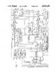
- FIG. 1is a diagramatic view showing a Subscriber Unit embodying the present invention.
- FIG. 2is a block diagram of the modulator portion of the modem processor shown in FIG. 1.
- FIG. 3is a block diagram of the DPSK conversion unit shown in FIG. 2.
- FIG. 4illustrates the structure and function of the FIR filter shown in FIG. 2.
- FIG. 5is a block diagram of the interpolator shown in FIG. 1.
- FIG. 6is a block diagram of the synthesizer shown in FIG. 1.
- FIG. 7is a modified form of the input portion of the system shown in FIG. 1.
- FIG. 8is a block diagram of the demodulator portion of the modem processor shown in FIG. 1.
- FIG. 9is a block diagram of the course frequency control module shown in FIG. 8.
- FIG. 10is a block diagram of the AFC and symbol timing module shown in FIG. 8.
- BLANKING Control meansfor causing a signal to be held at a predetermined amplitude level during actuation of the control means
- This inventionrelates to communications systems for the wireless transmission of multiple information signals utilizing digital time division circuits between a base station and one or more subscriber stations, and it particularly relates to the structure and functioning of such a subscriber station.
- the present inventionpertains to the same general type of communication system as is disclosed in co-pending patent application Ser. No. 713,923, filed Mar. 20, 1985, now U.S. Pat. No. 4,644,561, issued Feb. 17, 1987 and patent application Ser. No. 713,925, filed Mar. 20, 1985, now U.S. Pat. No. 4,675,863, issued June 23, 1987, both of these applications being incorporated herein by reference.
- FIG. 1a connector 10 for connection to the customer-provided equipment (CPE).
- CPEcustomer-provided equipment
- a line pair 12leads from the connector 10 to a SLIC 14 and is also connectable to a ringer circuit 16 through a relay 18.
- the SLIC 14is a standard chip for providing various functions such as battery voltage, overvoltage protection, ringing, signalling detection, as from a rotary dial, the handset status, line testing, etc.. It also contains the hybrid which separates a plurality of voices into ingoing and outgoing signals.
- the SLIC 14is coupled to a codec 20 having ingoing and outgoing lines to and from a baseband processor 22 whereby in the ingoing direction it converts analog voice signals to digital signals, i.e., 64 kbps u-law PCM, while in the outgoing direction, it converts the digital signals to analog voice signals.
- a codec 20having ingoing and outgoing lines to and from a baseband processor 22 whereby in the ingoing direction it converts analog voice signals to digital signals, i.e., 64 kbps u-law PCM, while in the outgoing direction, it converts the digital signals to analog voice signals.
- This direct access connectionserves two purposes: (1) to pass only digital signals, when so desired, thereby bypassing all analog connections, and (2) to allow direct access to the processors and memories for easy maintenance and test purposes.
- the baseband processor 22has several functions, one of which is to convert the 64 kbps PCM signal to 14.57. . . kbps by means of a transcoding function, such as, for example, provided by residual excited linear prediction (RELP). It also provides echo cancellation, and, in addition, acts like a control microprocessor, as, for example, by informing the synthesizer used in the system as to the desired operational frequency.
- the baseband processor 22is coupled to a serial EEPROM 30, which is an electrically erasable, non-volatile memory where selected bits may be electrically modified without erasing other bits stored therein. This EEPROM 30 is used to store both the subscriber identification number and the network indentification number (the base station with which it is used).
- the baseband processor 22is coupled to a full speed RAM 32 in which it stores the signals received therein.
- the RAM 32also includes a "cache" means, and, in addition, is used as a random access memory for RELP conversion, echo cancellation and other control functions.
- the baseband processor 22is also coupled to a half-speed EPROM 34 and a full-speed PROM 36 which store the RELP and echo cancellation functions as well as various other functions such as the control function.
- the baseband processor 22is, in addition, coupled via direct memory access (DMA) 38 to a modem processor 40.
- DMAdirect memory access
- the DMA 38prevents the occurrence of simultaneous access of RAM 32 by both the baseband and modem processors.
- the DMA interfaceis used to transfer voice and control data between the baseband and modem processors.
- the modem processor 40acts as the master and controls the baseband processor 22 via hold lines (not shown).
- the modem processor 40has the capability to access the baseband processor 22, halt its processing and cause the control lines, address and the data buses to assume the high impedence state of a three-state output. This permits the modem processor 40 to access the baseband processor's DMA memory through the DMA Interface and read or write to it.
- the modem processor 40asserting its XF bit, which is gated to the baseband processor's Hold input.
- the baseband processorreceives this command, it will finish executing the current instruction, stop its processing, cause its control, data and address busses to assume the high impedence state of a three-state output and then issue a Hold Acknowledge signal back to the modem processor.
- the modem processorissues the Hold command, it will continue on with other tasks while waiting for the baseband processor to send the Hold Acknowledge signal.
- the modem processorreceives the Hold Acknowledge signal, it will take control of the baseband processor's control, data, and address buses and then read or write to the DMA RAM 32.
- the baseband processoralso has the capability to lock out the modem processor by setting its own XF bit high. This bit is gated with the Hold from the modem processor and can override the Hold line at any point before the baseband processor goes into the Hold state.
- the modem processoruses 10 bits of the address bus and all 16 bits of the data bus. It also uses three control lines: Strobe, R/W, and DS.
- Either the baseband processor 22 or the modem processor 40, acting in either direction,may obtain signals from the RAM 32 in accordance with the signals described above.
- the two processorscommunicate with each other by way of a portion of RAM 32 that is set aside to be used as a cache.
- the modem processor 40is also coupled to a full speed PROM 44 which contains the program for this processor.
- the modem processor 40in its modulation mode, sends its signals via a FIFO 46 to an interpolator 48, these signals being at a sampling rate of 320 kHz.
- the interpolator 48effectively increases this sampling rate by 5 to convert it to 1600 kilosamples/second (1.6 megasamples/second).
- the interpolatorin conjunction with the crystal filter (herein after described), which acts as an integrator, effectively approximates a 5 tap FIR filter. This usage of digital and analog hardware to implement an FIR filter differs from the classic all digital hardware FIR implementation.
- the interpolator outputis fed into a PAL 50.
- the PALis configured as a type of mixer into which is fed a 400 kHz square wave, as indicated at 50, which comes from a timing generator 51, as well as the 1600 kilosample/second signal.
- the 1600 kilosample/second signalrepresents a 16-kilosymbol/second PSK signal with a zero carrier and a desired 20 kHz bandwidth.
- the PALcan be considered as a frequency translator.
- the PAL circuitwhich when configured to perform a 2's complement function controlled by a 400 kHz square wave effectively performs a time multiplexed quadrature mixing and effectively translates the 20 kHz wide baseband signal up to 400 kHz.
- the output from the PAL 50is a time multiplexed, frequency translated complex signal which is passed to the D/A converter 52 which converts the digital signal into an analog signal.
- the output from the D/A converter 52is fed to a mixer 54 into which is also fed a deglitching/blanking pulse 56 from a blanking generation module 58.
- Glitch energyis a major contribution to noise in a sampled data system. Glitch energy occurs during transitions from one input word to another. In a D/A converter, each incoming bit, depending upon its state, may cause a change in output analog level. Such changes resulting from the various bits usually do not occur simultaneously and therefore cause glitches.
- the output from mixer 54, indicated at 60,is fed to a mixer 62 in an upconverter, generally designated 64.
- the mixer 62has a 20 MHz input indicated at 65, which is common with a 20 MHz line 66.
- the output of mixer 62is the sum of 20 MHz from input 65 and the 400 kHz signal received from mixer 54, with a resultant output of 20.4 MHz.
- This outputis fed into a crystal filter 68 which passes only this sum, constituting the IF signal, to an amplifier 70.
- a synthesizeris shown at 72.
- this synthesizer 72is a synthesizer module of the type shown in patent application Ser. No. 840,908 filed Mar. 18, 1986, which provides an output LO1.
- a second circuitderives a second output LO2 wherein the output of LO2 tracks the output of LO1 at a frequency of 5 MHz below the frequency of LO1.
- the synthesizeruses as a reference the 80 MHz VCXO.
- the output LO1is fed through line 74 to a mixer 76 which also receives the IF output from amplifier 70.
- the synthesizeris operated to generate a frequency of 435.1 MHz, which when added to the 20.4 MHz, gives the desired frequency of 455.5 MHz.
- This outputis then amplified by a variable gain amplifier 80.
- the baseband processoron the basis of decoding certain signals from the base station, sends a gain control signal on line 81, through a D/A converter 82, to the variable gain amplifier 80.
- Variable gain amplifier 80has limited bandwidth and, therefore, does not pass the undesired difference frequency also produced by the mixer 76.
- the output of amplifier 80is passed through line 83 to a power amplifier 84, which accomplishes the final amplification before the RF signal passes through a relay 86 to an antenna 88.
- the unitemploys a system whereby a frame repeats every 45 milliseconds. In this system, the unit transmits during a portion of the second half of each frame and receives during a portion of the first half of the frame.
- One configurationmight be where both portions of the half are of equal length (although they may not neccessarily be equal).
- Another configuration (16-ary)might be where four equal length portions are available to the subscriber during an entire frame.
- Each of the four portionsmay be termed a slot.
- Each slotcontains, as part of its initial data, a unique word which is used by the unit to establish timing for reception of the remaining data in the slot.
- the first slot of the fourmay be preceded by an AM hole which is used to determine a slot arbitrarily designated by the base station as the first slot.
- the AM hole and the unique wordare part of the incoming signal from the base station.
- the duration of the AM holeis used to determine whether a particular RF channel is a control channel or a voice channel.
- a data signalis derived from the average magnitude of the signal represented at 116.
- a threshold proportional to said average magnitudeis compared to unaveraged magnitudes. If the threshold is not exceeded by said unaveraged magnitude for a predetermined period of time, it is assumed that an AM hole has been detected.
- the modem processor 40stores the time at which the AM hole was determined to occur in RAM 32.
- the baseband processoron the basis of (a) modulation mode (4-ary or 16-ary), (b) the time at which an AM hole occurred, as stored in RAM 32, and (c) the time at which a unique word was received, as separately determined by the baseband processor, produces initiating signals which indicate when the unit should be in a transmit mode or a receive mode. Such initiating signals are coupled via line 90 to frame timing module 91.
- the frame timing module 91converts the initiating signals into two series of pulses.
- One series of pulsesis connected via line 92 to enable power amplifier 84 and to actuate switch 86 so as to connect the output of amplifier 84 to antenna 88.
- the unitis designated to be in the transmit mode.
- switch 86When switch 86 is not so actuated, it is configured to connect antenna 88 to the input of a low noise amplifier 94.
- the other series of pulses from frame timing module 91are connected via line 93 to the amplifier 94 to enable this amplifier.
- the unitis designated to be in the receive mode during this series of pulses.
- the preamplifier 94passes received signals to a mixer 96, which also receives output LO2 from the synthesizer 72 through line 98.
- the output of mixer 96is fed to a crystal filter 100, the output of which, in turn, is fed to an IF amplifier 102.
- the modem processor 40passes via line 89, the aforementioned data signal, which is derived from the average magnitude of the signal represented at 116, to a D/A converter 104 which produces an analog AGC voltage signal which passes through line 106 to amplifier 102, thereby indicating to this amplifier how much gain is required in order to compensate so that the IF signal is always at the same amplitude.
- This amplifieralso receives the output from crystal filter 100.
- the output from amplifier 102passes to a mixer 108 into which is also applied an input of 20 MHz from line 109 to produce a resultant 400 kHz signal.
- This 400 kHz signalis then passed to an A/D module which consists of sample and hold circuits 110, and A/D converter 112 and a FIFO 114.
- the output from the A/D conversion moduleis 64 kilosamples/second and this output is fed through line 116 into the modem processor 40.
- the modem processor 40demodulates this signal and passes the demodulated data into the cache portion of RAM 32 which is accessed by the baseband processor 22 in which the RELP conversion takes place.
- the resultant outputhas 64 kbps PCM on a continuous serial basis. This output is fed to the codec, which converts it to an analog signal that is then fed to the SLIC which, in turn, feeds it to the telephone instrument; or, alternatively, the 16 kbps from the cache can be decoded into a digital signal which is fed to the UART 26.
- a loopbackis provided at 118 between two switches 120 and 122.
- This loopbackwhich is at the IF side rather than at the RF side, decreases the number of elements required.
- the training modeis that in which a known signal is sent out by the modem processor through the remainder of the transmitter elements set to IF amplifier 70. Because switches 120 and 122 are operated, the output of the amplifier 70 is connected to the input of crystal filter 100.
- an output of the baseband processor 22, indicated line 90,fuses to frame timing 91 and causes a pulse on line 93 to totally disable amplifier 94 during the training mode. Furthermore, during the training mode, frame timing 91 produces another pulse on line 92 which totally disables amplifier 84.
- the known signal generated by the modulatoris compared with the actual signal returned to the demodulator.
- a subsidiary programis then set up to compensate for variations due to various factors such as variations in temperature, component values, etc..
- the correction constantsare stored in the RAM 32. The modem applies these stored corrections to the received signals.
- the training modetakes place in intervals between actuation of the system.
- the synthesizer module 72contains an 80 MHz oscillator (VCXO) derived from the received signal.
- the 80 MHz signal generated by the oscillatorgoes through line 124 to a divide-by-4 circuit 126, the output of which goes to mixers 62 and 108. This output also goes to the two processors to provide clock pulses (square waves). In addition, it goes through line 124 to a divide-by-5 circuit 130 and then to timing module 51.
- the modem processordetermines any difference in frequency between the center frequency of the input signal and a submultiple of the clock frequency.
- Any resulting differenceis applied by the modem processor, via line 132, to a D/A converter 134.
- the output of the D/A converter 134is applied via line 136 and ADJ input 138 to the VCXO (hereinafter described) in such a manner as to change its frequency in the direction required to minimize the preceeding resulting difference.
- a lock loss detector signalis applied through line 140 to the baseband processor 22 to indicate when there is a loss of synchronization in the synthesizer.
- the modem processor 40comprises a DPSK converter 150 into which data is fed through line 152. The data is then fed at 16 kHz symbol/second rate, to a FIR filter 154.
- the output from FIR filter 154, indicated at 156,is asynchronous data comprising 10 complex samples/symbol, time-multiplexed IQ pairs. This output is fed to the FIFO 46, described above, where asynchronous to synchronous conversion takes place.
- the output from the FIFO 46in the form of 160,000 pairs of data words/second, is fed into the interpolator 48, described above, which demultiplexes the IQ pairs, and remultiplexes the IQ samples at a 1.6 MHz rate.
- the binary input sequenceis divided up into 4-bit symbols.
- the 4-bit symbolsdetermine the phase of the carrier during the given symbol period.
- the task of converting the binary input to the PSK waveformis performed by the modulator.
- FIG. 3shows how a sequence of samples (S i ), shown at 160, is transformed into a sequence of In-Phase (I) and Quadrature (Q) samples in the DPSK converter 150 of the modem processor 40.
- the symbolsare first inverse Gray encoded, as shown at 162. This is done to minimize the number of bit errors that occur due to the most likely incorrect symbol decisions in the demodulator.
- the output of the inverse Gray encoder 162is fed into a phase quantizer 164 which determines the absolute phase value ⁇ , introduced by the current symbol. This phase value is then fed into the differential encoder 166 which computes the absolute phase value ⁇ ' i .
- ⁇ ' irepresents the modulo 16 sum of the current differential phase ⁇ i and the previous phase ⁇ ' i-1 .
- the modulo 16 additioncorresponds to the modulo 360 addition that is performed when adding angles.
- the differential phase ⁇ ' iis fed into cosine and sine lookup tables to compute the I and Q components of the current symbol.
- the I and Q samplesare fed into the 6-tap Finite Impulse Response (FIR) filter 154 shown more specifically in FIG. 4.
- the function of the FIR filteris to create an oversampled PSK waveform from the I and Q samples.
- the Q samplesare fed into a bank of ten filters labeled "h Q'j ".
- the outputs of these 20 filtersare time division multiplexed as shown onto a single parallel bus that runs at a sampling rate which is ten times the sampling rate of the I,Q pairs at the input of the filter.
- the interpolator 48shown more specifically in FIG. 5, comprises an input 180 and a switch 182 that is connected to the I/Q memory 186 by a line 184, the switch 182 being switchable between the input 180 and a line 183.
- the output of the I/Q memory 186is connected to the PAL 50 by the line 187 and to the Q/I memory 190 by the line 188.
- Line 183is connected to the output of the Q/I memory 190.
- a 1.6 MHz inputis provided for both the I/Q and Q/I memories as indicated at 192 and 194 respectively.
- the interpolatordemultiplexes the multiplexed I,Q samples at a 160 kHz rate and then resamples and remultiplexes at an 800 kHz rate.
- the synthesizer 72functionally described above, is illustrated in FIG. 6, where there is shown an 80 MHz VCXO module 200 that receives a signal from the ADJ input 138. This input controls the exact frequency of the VCXO module.
- the output from the VCXO moduleis connected via line 202 to the synthesizer 204, which as stated above is of the type shown in patent application Ser. No. 840,908.
- This synthesizer 204is capable of synthesizing frequencies between 438.625 and 439.65 MHz in appropriate synchronism with the signals over line 202. The particular frequency is selected by an input signal over line 128 (also shown in FIG. 1).
- the output of the synthesizer 204is fed, via line 206 and filter 208 to become LO1.
- the output of synthesizer 204is also fed, via line 210, to a synchronous translator 212.
- the output of the VCXO 200is fed through line 214 to a divide by 16 module 216, the 5 MHz output of which is fed through line 218 to the synchronous translator module 212.
- the output on line 214is also connected to a reference output 221.
- Module 212subtracts the 5 MHz input from line 218 from the frequency on line 210, producing a difference frequency that is fed, via filter 220, to become LO2. In this manner, the frequencies appearing as LO2 vary between 433.625 and 434.65 MHz, whereby the frequency of the LO2 is always 5 MHz below the frequency of LO1.
- the output from the synthesizer 204, via line 222, and the output from the synchronous translator 212, via line 224,are combined in a synchronization detector 226 in such manner that if either the frequency on line 206 is not synchronous with the frequency on line 202 or the frequency output of synchronous translator 212 is not synchronous with the combination of the frequency on line 206 and the output frequency of the divide-by-16 module 216, a loss of synchronization (lock loss) signal is sent on line 140 (also shown in FIG. 1).
- FIG. 7illustrates a preferred circuit to test the customer interface.
- the baseband processor 22(shown in FIG. 1) digitally generates a 1 kHz sine wave that is passed to the codec 20 (shown in FIG. 1) that converts it to an analog sine wave which is, in turn, passed through the hybrid function of the SLIC 14 to line pair 12.
- a relay K(not shown in FIG. 1) is inserted immediately adjacent the connector 10 so that it may disconnect the connector from the circuit. Any reflected signal from the unterminated line pair 12 at the open relay K is returned through the hybrid function of the SLIC and is converted to a digital signal by the codec 20.
- This digital signalis fed to the baseband processor 22 which compares the reflected signal with the originating signal and determines whether any undesired impedences or connections, e.g. grounds, are present on the line pair 12.
- FIG. 8illustrates the demodulator portion of the modem processor 40 and shows the 400 kHz output from the mixer 108 (shown in FIG. 1) applied to the high precision sample and hold circuit 110, which has an aperture uncertainty of 25 nanoseconds or less, the output of which is passed to the A/D converter 112.
- the output of A/D converter 112is fed through line 116 to the modem processor (all as shown in FIG. 1).
- the input at line 116comprises time multiplexed I and Q samples (which may have some cross-product distortion) in the form of two complex sample pairs/symbol. Said time multiplexed I and Q samples are applied to the demultiplexer 290 where they are demultiplexed.
- the demultiplexed I and Q samplesare applied to an equalizer module 300 whose objectives are to minimize (a) error energy of the received data stream, (b) modified error energy of the data stream delayed by 0.05 T (T being 1/16000 of a second), (c) modified error energy of the data stream advanced by 0.05 T, (d) energy of the data stream from the adjacent upper channel (desired receive frequency plus 25 kHz), and (e) energy from the data stream of the adjacent lower channel (desired receive frequency minus 25 kHz).
- the equalizeris a complex 28 tap FIR filter wherein the filter weights are determined by minimizing the above five objectives.
- five training signalsare generated by the modulator. These are: (a) a signal at the desired frequency wherein the receiver and transmitter clocks are synchronized, (b) the same signal as (a) but wherein the receiver clock is advanced with respect to the transmitter clock by 0.05 T, (c) the same signal as (b) except that it is delayed by 0.05 T, (d) the same signal as (a) but wherein the carrier frequency is increased by 25 kHz, and (e) the same signal as (d) except that the carrier frequency is decreased by 25 kHz.
- the modem processormodifies the transmit FIR filter coefficients in order to shift the filter center frequency by 25 kHz.
- weighting coefficientsare stored in the modem processor 40.
- the equalized I and Q samplesare fed into a module 302 which produces an output which is the arc tangent of the ratio of the equalized Q and I samples.
- This outputshown at 304, represents the phase of the received signal.
- the equalized I and Q samplesare also simultaneously fed to a course frequency module 306, shown in greater detail in FIG. 9.
- the I and Q samplesare summed to produce a lower sideband 308 (as shown in FIG. 9), and simultaneously the difference between the I and Q samples is formed to produce an upper sideband 310.
- a magnitude calculationis then performed on both the upper and lower sidebands, as indicated at 312 and 314.
- the difference operation between the magnitudestake place at 316. This difference indicated at 318, represents a frequency error.
- the output 304 of the arc tangent module 302is fed to the AFC and symbol time tracking module 320 (which is shown in greater detail in FIG. 10).
- the phase correction value, indicated at 322 in FIG. 10,is subtracted from the detected phase 304, resulting in the corrected phase indicated at line 324.
- the corrected phase 324is fed into a symbol detector 326 which detects the current symbol in terms of the phase value and quantizes the phase to the nearest 22.5 degree increment.
- the quantized phase, indicated at 328is subtracted from the corrected phase 324 at 330. This results in the phase error signal indicated at 332.
- This error signal 332is fed into a second order loop filter, generally indicated at 334, which computes the phase correction value, indicated at line 336, as well as the frequency correction signal, shown at 338.
- This frequency correction signalis applied to the VCXO through line 132 shown in FIG. 1.
- the error signal 332is fed through line 340 to a symbol timing tracking module 342 which also receives the output from the symbol detection module 326 through line 344.
- the symbol timing tracking module 342contains an algorithm which tracks the phase over a number of predetermined symbols, looking at the starting phase of the first symbol and the phase of the last symbol, and then determines the slope. It tries to determine from the phase versus time function where the zero crossings occur. By looking at the zero crossings that actually occurred and comparing them with where they should have occurred, a timing adjustment is computed that will correct for the difference. The symbol clock will be adjusted at the beginning of the next slot.
- the symbol timing tracking module 342provides an output 346 which is applied to the timing module 51 (shown in FIG. 1).
- the frequency correction signal 338 from the AFC and symbol timing module 320is applied to a weighting module 348 (as shown in FIG. 8) where it is weighted.
- the output 350 from module 348is fed into a summing module 352 where signal 350 is summed with the output 318 of module 306 to provide an output 354 which is applied to the D/A converter 134.
- the output from D/A converteris shown in FIG. 1 as being applied to the synthesizer at 138.
- the inventionprovides for various separate elements, it is possible to include the functions of many of these elements such as, for example, the full speed PROM 44, the FIFO 46, the interpolator 48 and the PAL 50, within a modem processor of sufficiently large capacity. This may also be true of such elements as the frame timing 91, the blanking generation 58, the timing means 51, the divide-by-4, the divide-by-5 and some or all of the synthesizer 72.
- the baseband processor and the modem processormay also be combined in a simple unit which may also include the codec and the UART.
Landscapes
- Engineering & Computer Science (AREA)
- Signal Processing (AREA)
- Computer Networks & Wireless Communication (AREA)
- Physics & Mathematics (AREA)
- Power Engineering (AREA)
- Theoretical Computer Science (AREA)
- Mathematical Physics (AREA)
- Computer Hardware Design (AREA)
- Spectroscopy & Molecular Physics (AREA)
- Digital Transmission Methods That Use Modulated Carrier Waves (AREA)
- Mobile Radio Communication Systems (AREA)
- Cable Transmission Systems, Equalization Of Radio And Reduction Of Echo (AREA)
- Transceivers (AREA)
- Time-Division Multiplex Systems (AREA)
Abstract
Description
θ'.sub.i =(θ.sub.i +θ'.sub.i-1)MOD 16
Claims (10)
Priority Applications (107)
| Application Number | Priority Date | Filing Date | Title |
|---|---|---|---|
| US06/893,916US4825448A (en) | 1986-08-07 | 1986-08-07 | Subscriber unit for wireless digital telephone system |
| AU64297/86AAU570152B1 (en) | 1986-08-07 | 1986-10-21 | Subscriber unit |
| IN937/DEL/86AIN170912B (en) | 1986-08-07 | 1986-10-23 | |
| SE8604661ASE8604661L (en) | 1986-08-07 | 1986-10-31 | COMMUNICATIONS |
| IL9483786AIL94837A (en) | 1986-08-07 | 1986-11-04 | Subscriber unit for wireless digital telephone system |
| IL9483986AIL94839A (en) | 1986-08-07 | 1986-11-04 | Subscriber unit for wireless digital telephone system |
| IL9483686AIL94836A (en) | 1986-08-07 | 1986-11-04 | Subscriber unit for wireless digital telephone system |
| IL9483886AIL94838A (en) | 1986-08-07 | 1986-11-04 | Subscriber unit for wireless digital telephone system |
| IL94835AIL94835A (en) | 1986-08-07 | 1986-11-04 | Dpsk converter for modem |
| IL80497AIL80497A (en) | 1986-08-07 | 1986-11-04 | Subscriber unit for wireless digital telephone system |
| GB8627428AGB2194711B (en) | 1986-08-07 | 1986-11-17 | Subscriber unit for wireless digital telephone system |
| IE383891AIE67265B1 (en) | 1986-08-07 | 1986-11-18 | A transmission system |
| IE383591AIE67262B1 (en) | 1986-08-07 | 1986-11-18 | A modem |
| IE383691AIE67263B1 (en) | 1986-08-07 | 1986-11-18 | An interpolator |
| IE304586AIE67260B1 (en) | 1986-08-07 | 1986-11-18 | Subscriber unit for wireless digital telephone system |
| IE383791AIE67264B1 (en) | 1986-08-07 | 1986-11-18 | Subscriber unit for wireless digital telephone system |
| NO864618ANO172090C (en) | 1986-08-07 | 1986-11-19 | SUBSCRIPTION UNIT FOR WIRELESS DIGITAL PHONE SYSTEM |
| FR868616232AFR2602622B1 (en) | 1986-08-07 | 1986-11-21 | SUBSCRIBER ASSEMBLY FOR DIGITAL WIRELESS TELEPHONY; MISCELLANEOUS MODEM AND DEVICES (FREQUENCY SYNTHESIZER ...) FOR THIS ASSEMBLY |
| CH4696/86ACH674435A5 (en) | 1986-08-07 | 1986-11-24 | |
| BE0/217462ABE905822A (en) | 1986-08-07 | 1986-11-27 | SUBSCRIBER ASSEMBLY FOR DIGITAL WIRELESS TELEPHONY; MISCELLANEOUS MODEM AND DEVICE (FREQUENCY SYNTHESIZER ...) FOR THIS ASSEMBLY. |
| KR1019860010125AKR900005142B1 (en) | 1986-08-07 | 1986-11-28 | Subscriber unit for wireless digital telephone system |
| ES8603224AES2003951A6 (en) | 1986-08-07 | 1986-11-28 | DIGITAL WIRELESS SUBSCRIBER TELEPHONE DEVICE TO CONNECT TO A BASE CENTRAL |
| FI864943AFI85077C (en) | 1986-08-07 | 1986-12-03 | ABONNENTENHET FOER ETT TRAODLOEST, DIGITALT TELEFONSYSTEM. |
| DE3644066ADE3644066C2 (en) | 1986-08-07 | 1986-12-22 | Subscriber unit for a wireless digital telephone system |
| MX4870AMX164955B (en) | 1986-08-07 | 1987-01-06 | SUBSCRIBER UNIT FOR WIRELESS DIGITAL TELEPHONE SYSTEM |
| AR87306644AAR244479A1 (en) | 1986-08-07 | 1987-01-30 | Subscriber unit for telephone system |
| AT0036587AAT404203B (en) | 1986-08-07 | 1987-02-19 | SUBSCRIBER UNIT FOR A WIRELESS DIGITAL TELEPHONE SYSTEM |
| NL8700645ANL192170C (en) | 1986-08-07 | 1987-03-18 | Subscriber unit for a wireless, phase-modulated time-division multiplex digital telephone system. |
| JP62074573AJPH0773384B2 (en) | 1986-08-07 | 1987-03-30 | Subscriber equipment for wireless digital telephone systems |
| BR8701441ABR8701441A (en) | 1986-08-07 | 1987-03-30 | SUBSCRIBER UNIT FOR WIRELESS DIGITAL TELEPHONE SYSTEM, MODEM, FAULT SUPPRESSOR SYSTEM, INTERPOLER, FREQUENCY SYNTHESIZER, SYSTEM, AFC TRACKING SYSTEM AND SYMBOL REGULATION, FREQUENCY CONVERTER AND SAMPLE AND RETENTION AMPLIFIER |
| DK198701789ADK175148B1 (en) | 1986-08-07 | 1987-04-08 | Digital wireless telephone system |
| CA000534177ACA1263900A (en) | 1986-08-07 | 1987-04-08 | Subscriber unit for wireless digital telephone system |
| CN87103449ACN1009610B (en) | 1986-08-07 | 1987-05-12 | Home unit for wireless digital telephone system |
| IT8747921AIT1207336B (en) | 1986-08-07 | 1987-05-13 | USER UNIT FOR DIGITAL RADIO TELEPHONE SYSTEM AND COMPONENT DEVICES |
| FR878710227AFR2602933B1 (en) | 1986-08-07 | 1987-07-20 | SUBSCRIBER ASSEMBLY FOR DIGITAL WIRELESS TELEPHONY; MISCELLANEOUS MODEM AND DEVICES (FREQUENCY SYNTHESIZER ...) FOR THIS ASSEMBLY |
| FR878710226AFR2602944B1 (en) | 1986-08-07 | 1987-07-20 | SUBSCRIBER ASSEMBLY FOR DIGITAL WIRELESS TELEPHONY; MISCELLANEOUS MODEM AND DEVICES (FREQUENCY SYNTHESIZER ...) FOR THIS ASSEMBLY |
| FR8710223AFR2607336B1 (en) | 1986-08-07 | 1987-07-20 | SUBSCRIBER ASSEMBLY FOR DIGITAL WIRELESS TELEPHONY; MISCELLANEOUS MODEM AND DEVICES (FREQUENCY SYNTHESIZER ...) FOR THIS ASSEMBLY |
| FR878710224AFR2602938B1 (en) | 1986-08-07 | 1987-07-20 | SUBSCRIBER ASSEMBLY FOR DIGITAL WIRELESS TELEPHONY; MISCELLANEOUS MODEM AND DEVICES (FREQUENCY SYNTHESIZER ...) FOR THIS ASSEMBLY |
| FR878710221AFR2602935B1 (en) | 1986-08-07 | 1987-07-20 | SUBSCRIBER ASSEMBLY FOR DIGITAL WIRELESS TELEPHONY; MISCELLANEOUS MODEM AND DEVICES (FREQUENCY SYNTHESIZER ...) FOR THIS ASSEMBLY |
| FR878710222AFR2602928B1 (en) | 1986-08-07 | 1987-07-20 | SUBSCRIBER ASSEMBLY FOR DIGITAL WIRELESS TELEPHONY; MISCELLANEOUS MODEM AND DEVICES (FREQUENCY SYNTHESIZER ...) FOR THIS ASSEMBLY |
| FR8710220AFR2602941B1 (en) | 1986-08-07 | 1987-07-20 | SUBSCRIBER ASSEMBLY FOR DIGITAL WIRELESS TELEPHONY; MISCELLANEOUS MODEM AND DEVICES (FREQUENCY SYNTHESIZER ...) FOR THIS ASSEMBLY |
| FR8710228AFR2602934B1 (en) | 1986-08-07 | 1987-07-20 | SUBSCRIBER ASSEMBLY FOR DIGITAL WIRELESS TELEPHONY; MISCELLANEOUS MODEM AND DEVICES (FREQUENCY SYNTHESIZER ...) FOR THIS ASSEMBLY |
| FR878710225AFR2602929B1 (en) | 1986-08-07 | 1987-07-20 | WIRELESS TELEPHONY SUBSCRIBER ASSEMBLY; MISCELLANEOUS MODEM AND DEVICES (FREQUENCY SYNTHESIZER ...) FOR THIS ASSEMBLY |
| GB8717218AGB2194404B (en) | 1986-08-07 | 1987-07-21 | Deglitching system |
| GB8717225AGB2199206B (en) | 1986-08-07 | 1987-07-21 | A subscriber unit |
| GB8717222AGB2198915B (en) | 1986-08-07 | 1987-07-21 | A transmission system |
| GB8717224AGB2199214B (en) | 1986-08-07 | 1987-07-21 | An upconverter |
| GB8717219AGB2194418B (en) | 1986-08-07 | 1987-07-21 | An interpolator |
| GB8717221AGB2194403B (en) | 1986-08-07 | 1987-07-21 | A frequency synthesizer system |
| GB8717220AGB2194708B (en) | 1986-08-07 | 1987-07-21 | Subscriber unit for wireless digital telephone system |
| GB8717217AGB2194417B (en) | 1986-08-07 | 1987-07-21 | A modem |
| GB8717223AGB2198916B (en) | 1986-08-07 | 1987-07-21 | A symbol timing tracking and automatic frequency control system |
| GR871236AGR871236B (en) | 1986-08-07 | 1987-08-04 | Subscriber unit for wireless digital telephone system |
| PT85503APT85503B (en) | 1986-08-07 | 1987-08-06 | UNIT OF SUBSCRIBER FOR DIGITAL WIRELESS TELEPHONE SYSTEM |
| TR87/0515ATR23782A (en) | 1986-08-07 | 1987-08-28 | SUBSCRIBER UENITES FOR RADIO DIGITAL TELEPHONE SYSTEM |
| AU81370/87AAU579781B2 (en) | 1986-08-07 | 1987-11-18 | Frequency convertor |
| AU81363/87AAU577729B2 (en) | 1986-08-07 | 1987-11-18 | Modem for a digital subscriber unit |
| AU81367/87AAU579780B2 (en) | 1986-08-07 | 1987-11-18 | Frequency synthesizer |
| AU81368/87AAU577987B2 (en) | 1986-08-07 | 1987-11-18 | Tdm system |
| AU81371/87AAU579782B2 (en) | 1986-08-07 | 1987-11-18 | AMP and A to D converter system |
| AU81365/87AAU579779B2 (en) | 1986-08-07 | 1987-11-18 | Interpolator |
| AU81364/87AAU579778B2 (en) | 1986-08-07 | 1987-11-18 | Deglitching system |
| AU81369/87AAU576991B2 (en) | 1986-08-07 | 1987-11-18 | Timing tracking and afc system |
| AU81366/87AAU579966B2 (en) | 1986-08-07 | 1987-11-18 | Subscriber unit |
| US07/256,415US4893317A (en) | 1986-08-07 | 1988-10-12 | Digital signals and frequency correction in a digital wireless system |
| US07/256,580US4943983A (en) | 1986-08-07 | 1988-10-12 | Subscriber unit for wireless digital telephone system |
| US07/256,579US4994802A (en) | 1986-08-07 | 1988-10-12 | Subscriber unit for wireless digital telephone system |
| US07/256,416US4996697A (en) | 1986-08-07 | 1988-10-12 | Deglitching means for digital communication systems |
| US07/256,420US5101418A (en) | 1986-08-07 | 1988-10-12 | Digital time-multiplexed quadrature frequency upconverter |
| US07/256,577US5177741A (en) | 1986-08-07 | 1988-10-12 | Subscriber unit for wireless digital telephone system |
| US07/256,557US4881240A (en) | 1986-08-07 | 1988-10-12 | AM equalizer circuit for digital systems |
| CA000608566ACA1338743C (en) | 1986-08-07 | 1989-08-16 | Subscriber unit for wireless digital telephone system |
| CA000608562ACA1272817A (en) | 1986-08-07 | 1989-08-16 | Subscriber unit for wireless digital telephone system |
| CA000608563ACA1303687C (en) | 1986-08-07 | 1989-08-16 | Subscriber unit for wireless digital telephone system |
| CA000608564ACA1303686C (en) | 1986-08-07 | 1989-08-16 | Subscriber unit for wireless digital telephone system |
| CA000608565ACA1319957C (en) | 1986-08-07 | 1989-08-16 | Subscriber unit for wireless digital telephone system |
| CA000611685ACA1272317A (en) | 1986-08-07 | 1989-09-15 | Subscriber unit for wireless digital telephone system |
| CA000611686ACA1274630A (en) | 1986-08-07 | 1989-09-15 | Subscriber unit for wireless digital telephone system |
| CA000611684ACA1272316B (en) | 1986-08-07 | 1989-09-15 | Subscriber unit for wireless digital telephone system |
| US07/419,501US5067141A (en) | 1986-08-07 | 1989-10-10 | Interpolator for varying a signal sampling rate |
| US07/433,995US5168507A (en) | 1986-08-07 | 1989-11-09 | Automatic adaptive equalizer |
| FI900737AFI85317C (en) | 1986-08-07 | 1990-02-14 | Correction system and correction circuit |
| IL94838AIL94838A0 (en) | 1986-08-07 | 1990-06-22 | Subscriber unit for wireless digital telephone system |
| IL94837AIL94837A0 (en) | 1986-08-07 | 1990-06-22 | Subscriber unit for wireless digital telephone system |
| IL94839AIL94839A0 (en) | 1986-08-07 | 1990-06-22 | Subscriber unit for wireless digital telephone system |
| IL94836AIL94836A0 (en) | 1986-08-07 | 1990-06-22 | Subscriber unit for wireless digital telephone system |
| IL94835AIL94835A0 (en) | 1986-08-07 | 1990-06-22 | Subscriber unit for wireless digital telephone system |
| NL9002801ANL9002801A (en) | 1986-08-07 | 1990-12-18 | SYMBOL TIME TRACK AND AUTOMATIC FREQUENCY CONTROL DEVICE FOR A COMMUNICATION SYSTEM. |
| NL9002803ANL9002803A (en) | 1986-08-07 | 1990-12-18 | SYSTEM FOR CONVERTING AN ANALOGUE SIGNAL TO A DIGITAL SIGNAL. |
| NL9002797ANL193712C (en) | 1986-08-07 | 1990-12-18 | Modem for converting a digital input signal into a phase shift modulated output signal by means of differential phase shift modulation. |
| NL9002802ANL9002802A (en) | 1986-08-07 | 1990-12-18 | DIGITAL INVERTER. |
| NL9002799ANL193577C (en) | 1986-08-07 | 1990-12-18 | Frequency synthesizer for a digital communication system. |
| NL9002800ANL9002800A (en) | 1986-08-07 | 1990-12-18 | DEMODULATOR FOR A MODEM OF A DIGITAL COMMUNICATION SYSTEM. |
| NL9002806ANL9002806A (en) | 1986-08-07 | 1990-12-18 | INTERPOLATOR. |
| NL9002798ANL9002798A (en) | 1986-08-07 | 1990-12-18 | DEGLITCHING DEVICE FOR A CONVERTER OF A TELECOMMUNICATIONS SYSTEM. |
| NL9002805ANL9002805A (en) | 1986-08-07 | 1990-12-18 | SUBSCRIBER UNIT FOR A WIRELESS DIGITAL TELEPHONE SYSTEM. |
| US07/853,334US5159705A (en) | 1986-08-07 | 1992-03-13 | Frequency synthesizer circuit |
| US08/264,200US5842137A (en) | 1986-08-07 | 1994-06-22 | Subscriber unit for wireless digital telephone system |
| SE9402221ASE518848C2 (en) | 1986-08-07 | 1994-06-23 | Subscriber unit and equalizer circuit for a digital telephony system |
| HK64194AHK64194A (en) | 1986-08-07 | 1994-07-07 | Subscriber unit for wireless digital telephone system |
| JP08234687AJP3110681B2 (en) | 1986-08-07 | 1996-08-16 | Subscriber equipment system for wireless digital telephone systems. |
| JP03049698AJP3345334B2 (en) | 1986-08-07 | 1998-01-28 | Adaptive equalizer for subscriber unit systems for wireless digital telephone systems. |
| DK199801517ADK175672B1 (en) | 1986-08-07 | 1998-11-19 | Subscriber equipment for wireless digital telephony - has control and MODEM processors directly coupled in assembly containing CODEC and universal transmitter receiver |
| SE9902040ASE523252C2 (en) | 1986-08-07 | 1999-06-03 | Subscriber unit for a digital, wireless telephony system |
| SE0400130ASE527060C2 (en) | 1986-08-07 | 2004-01-23 | System and method for symbol rate tracking and automatic frequency control |
| DK200400536ADK175639B1 (en) | 1986-08-07 | 2004-04-02 | Subscriber equipment for wireless digital telephony - has control and MODEM processors directly coupled in assembly containing CODEC and universal transmitter receiver |
| SE0401973ASE528439C2 (en) | 1986-08-07 | 2004-08-03 | Frequency raising converter circuit |
Applications Claiming Priority (1)
| Application Number | Priority Date | Filing Date | Title |
|---|---|---|---|
| US06/893,916US4825448A (en) | 1986-08-07 | 1986-08-07 | Subscriber unit for wireless digital telephone system |
Related Child Applications (8)
| Application Number | Title | Priority Date | Filing Date |
|---|---|---|---|
| US07/256,416DivisionUS4996697A (en) | 1986-08-07 | 1988-10-12 | Deglitching means for digital communication systems |
| US07256578Division | 1988-10-12 | ||
| US07/256,420DivisionUS5101418A (en) | 1986-08-07 | 1988-10-12 | Digital time-multiplexed quadrature frequency upconverter |
| US07/256,557DivisionUS4881240A (en) | 1986-08-07 | 1988-10-12 | AM equalizer circuit for digital systems |
| US07/256,579DivisionUS4994802A (en) | 1986-08-07 | 1988-10-12 | Subscriber unit for wireless digital telephone system |
| US07/256,580ContinuationUS4943983A (en) | 1986-08-07 | 1988-10-12 | Subscriber unit for wireless digital telephone system |
| US07/256,415DivisionUS4893317A (en) | 1986-08-07 | 1988-10-12 | Digital signals and frequency correction in a digital wireless system |
| US07/256,577DivisionUS5177741A (en) | 1986-08-07 | 1988-10-12 | Subscriber unit for wireless digital telephone system |
Publications (1)
| Publication Number | Publication Date |
|---|---|
| US4825448Atrue US4825448A (en) | 1989-04-25 |
Family
ID=25402332
Family Applications (10)
| Application Number | Title | Priority Date | Filing Date |
|---|---|---|---|
| US06/893,916Expired - LifetimeUS4825448A (en) | 1986-08-07 | 1986-08-07 | Subscriber unit for wireless digital telephone system |
| US07/256,579Expired - LifetimeUS4994802A (en) | 1986-08-07 | 1988-10-12 | Subscriber unit for wireless digital telephone system |
| US07/256,557Expired - LifetimeUS4881240A (en) | 1986-08-07 | 1988-10-12 | AM equalizer circuit for digital systems |
| US07/256,580Expired - LifetimeUS4943983A (en) | 1986-08-07 | 1988-10-12 | Subscriber unit for wireless digital telephone system |
| US07/256,420Expired - LifetimeUS5101418A (en) | 1986-08-07 | 1988-10-12 | Digital time-multiplexed quadrature frequency upconverter |
| US07/256,416Expired - LifetimeUS4996697A (en) | 1986-08-07 | 1988-10-12 | Deglitching means for digital communication systems |
| US07/256,415Expired - LifetimeUS4893317A (en) | 1986-08-07 | 1988-10-12 | Digital signals and frequency correction in a digital wireless system |
| US07/256,577Expired - LifetimeUS5177741A (en) | 1986-08-07 | 1988-10-12 | Subscriber unit for wireless digital telephone system |
| US07/853,334Expired - LifetimeUS5159705A (en) | 1986-08-07 | 1992-03-13 | Frequency synthesizer circuit |
| US08/264,200Expired - LifetimeUS5842137A (en) | 1986-08-07 | 1994-06-22 | Subscriber unit for wireless digital telephone system |
Family Applications After (9)
| Application Number | Title | Priority Date | Filing Date |
|---|---|---|---|
| US07/256,579Expired - LifetimeUS4994802A (en) | 1986-08-07 | 1988-10-12 | Subscriber unit for wireless digital telephone system |
| US07/256,557Expired - LifetimeUS4881240A (en) | 1986-08-07 | 1988-10-12 | AM equalizer circuit for digital systems |
| US07/256,580Expired - LifetimeUS4943983A (en) | 1986-08-07 | 1988-10-12 | Subscriber unit for wireless digital telephone system |
| US07/256,420Expired - LifetimeUS5101418A (en) | 1986-08-07 | 1988-10-12 | Digital time-multiplexed quadrature frequency upconverter |
| US07/256,416Expired - LifetimeUS4996697A (en) | 1986-08-07 | 1988-10-12 | Deglitching means for digital communication systems |
| US07/256,415Expired - LifetimeUS4893317A (en) | 1986-08-07 | 1988-10-12 | Digital signals and frequency correction in a digital wireless system |
| US07/256,577Expired - LifetimeUS5177741A (en) | 1986-08-07 | 1988-10-12 | Subscriber unit for wireless digital telephone system |
| US07/853,334Expired - LifetimeUS5159705A (en) | 1986-08-07 | 1992-03-13 | Frequency synthesizer circuit |
| US08/264,200Expired - LifetimeUS5842137A (en) | 1986-08-07 | 1994-06-22 | Subscriber unit for wireless digital telephone system |
Country Status (28)
| Country | Link |
|---|---|
| US (10) | US4825448A (en) |
| JP (3) | JPH0773384B2 (en) |
| KR (1) | KR900005142B1 (en) |
| CN (1) | CN1009610B (en) |
| AR (1) | AR244479A1 (en) |
| AT (1) | AT404203B (en) |
| AU (10) | AU570152B1 (en) |
| BE (1) | BE905822A (en) |
| BR (1) | BR8701441A (en) |
| CA (3) | CA1263900A (en) |
| CH (1) | CH674435A5 (en) |
| DK (1) | DK175148B1 (en) |
| ES (1) | ES2003951A6 (en) |
| FI (1) | FI85077C (en) |
| FR (10) | FR2602622B1 (en) |
| GB (10) | GB2194711B (en) |
| GR (1) | GR871236B (en) |
| HK (1) | HK64194A (en) |
| IE (1) | IE67260B1 (en) |
| IL (1) | IL80497A (en) |
| IN (1) | IN170912B (en) |
| IT (1) | IT1207336B (en) |
| MX (1) | MX164955B (en) |
| NL (8) | NL192170C (en) |
| NO (1) | NO172090C (en) |
| PT (1) | PT85503B (en) |
| SE (5) | SE8604661L (en) |
| TR (1) | TR23782A (en) |
Cited By (38)
| Publication number | Priority date | Publication date | Assignee | Title |
|---|---|---|---|---|
| US5008900A (en)* | 1989-08-14 | 1991-04-16 | International Mobile Machines Corporation | Subscriber unit for wireless digital subscriber communication system |
| US5146473A (en)* | 1989-08-14 | 1992-09-08 | International Mobile Machines Corporation | Subscriber unit for wireless digital subscriber communication system |
| US5291474A (en)* | 1989-05-18 | 1994-03-01 | Nokia Mobile Phones Ltd. | Procedure for forming frequencies of a digital radio telephone |
| US5428604A (en)* | 1989-04-20 | 1995-06-27 | Nec Corporation | Training method for an echo canceller for use in a voice conference system |
| EP0660222A1 (en)* | 1993-12-16 | 1995-06-28 | AT&T Corp. | Data converter with fifo |
| US5495508A (en)* | 1987-11-20 | 1996-02-27 | Interdigital Technology Corporation | Base station emulator |
| US5530722A (en)* | 1992-10-27 | 1996-06-25 | Ericsson Ge Mobile Communications Inc. | Quadrature modulator with integrated distributed RC filters |
| US5537608A (en)* | 1992-11-13 | 1996-07-16 | International Business Machines Corporation | Personal communicator apparatus |
| US5548541A (en)* | 1994-08-08 | 1996-08-20 | Interstate Electronics Corporation | Finite impulse response filter for modulator in digital data transmission system |
| US5555258A (en)* | 1994-06-17 | 1996-09-10 | P. Stuckey McIntosh | Home personal communication system |
| US5610942A (en)* | 1995-03-07 | 1997-03-11 | Chen; Keping | Digital signal transcoder and method of transcoding a digital signal |
| US5657358A (en) | 1985-03-20 | 1997-08-12 | Interdigital Technology Corporation | Subscriber RF telephone system for providing multiple speech and/or data signals simultaneously over either a single or plurality of RF channels |
| US5682403A (en)* | 1995-05-04 | 1997-10-28 | Wavelink Communications | Spread spectrum communication network signal processor |
| NL9700008A (en)* | 1989-08-14 | 1997-12-01 | Interdigital Tech Corp | Subscriber equipment for digital radio communications system |
| US5727023A (en)* | 1992-10-27 | 1998-03-10 | Ericsson Inc. | Apparatus for and method of speech digitizing |
| US5734979A (en)* | 1995-05-04 | 1998-03-31 | Interwave Communications International, Ltd. | Cellular base station with intelligent call routing |
| US5745523A (en)* | 1992-10-27 | 1998-04-28 | Ericsson Inc. | Multi-mode signal processing |
| US5781582A (en)* | 1995-05-04 | 1998-07-14 | Interwave Communications International Ltd. | Frequency agile transceiver with multiple frequency synthesizers per transceiver |
| US5787115A (en)* | 1995-12-28 | 1998-07-28 | Northern Telecom Limited | Key telephone system without common control |
| US5801695A (en)* | 1994-12-09 | 1998-09-01 | Townshend; Brent | High speed communications system for analog subscriber connections |
| US5812605A (en)* | 1994-12-29 | 1998-09-22 | Motorola, Inc. | Multi-channel digital transceiver and method |
| US5825829A (en)* | 1995-06-30 | 1998-10-20 | Scientific-Atlanta, Inc. | Modulator for a broadband communications system |
| US5828698A (en)* | 1995-02-28 | 1998-10-27 | Hughes Electronics | Data flow management method for CDPD demodulator operating without CDPD clock |
| US5842137A (en)* | 1986-08-07 | 1998-11-24 | Interdigital Technology Corporation | Subscriber unit for wireless digital telephone system |
| US5852604A (en) | 1993-09-30 | 1998-12-22 | Interdigital Technology Corporation | Modularly clustered radiotelephone system |
| US5867537A (en)* | 1992-10-27 | 1999-02-02 | Ericsson Inc. | Balanced tranversal I,Q filters for quadrature modulators |
| US5930297A (en)* | 1989-11-20 | 1999-07-27 | Interdigital Technology Corporation | Base station emulator |
| US6058104A (en)* | 1994-06-17 | 2000-05-02 | Home Wireless Networks, Inc. | Communications webs for PSTN subscribers |
| US6188720B1 (en)* | 1995-05-12 | 2001-02-13 | Itt Manufacturing Enterprises, Inc. | Modulation and signaling converter |
| US20010008519A1 (en)* | 1987-11-20 | 2001-07-19 | Kaewell John David | Base station emulator |
| US6404761B1 (en) | 1994-06-17 | 2002-06-11 | Home Wireless Networks, Inc. | Communications webs with personal communications links for PSTN subscribers |
| US6418131B1 (en) | 1994-06-17 | 2002-07-09 | Lake Communications Limited | Spectrum monitoring for PSTN subscribers |
| US6418129B1 (en) | 1997-11-03 | 2002-07-09 | Bellsouth Intellectual Property Corporation | Wireless subscription management with dynamic allocation of unique network addresses |
| US6452948B1 (en)* | 1998-06-10 | 2002-09-17 | Sicom, Inc. | Method for baud-clock phase synchronization in a TDMA digital communications system and apparatus therefor |
| EP1164708A3 (en)* | 2000-06-01 | 2003-10-22 | TRW Inc. | Long range two way low power communication device |
| US6690749B2 (en) | 1994-12-09 | 2004-02-10 | Brent Townshend | High speed encoding and decoding apparatus and method for analog subscriber connections |
| US10009686B1 (en)* | 2017-04-17 | 2018-06-26 | Cirrus Logic, Inc. | Fully-differential current digital-to-analog converter |
| US20220304113A1 (en)* | 2021-03-16 | 2022-09-22 | Inseego Corp. | Cellular modem interfaces for modularization |
Families Citing this family (53)
| Publication number | Priority date | Publication date | Assignee | Title |
|---|---|---|---|---|
| US4777633A (en)* | 1987-08-14 | 1988-10-11 | International Mobile Machines Corp. | Base station for wireless digital telephone system |
| BE1004074A3 (en)* | 1987-07-08 | 1992-09-22 | Internat Mobile Machines Corp | System for initialising a communication channel between a subscriber stationand a base station in a communication system |
| FR2645690B1 (en)* | 1987-07-08 | 1997-12-19 | Int Mobile Machines | DEVICE FOR INITIALIZING A COMMUNICATION CHANNEL BETWEEN A SUBSCRIBER STATION AND A BASE STATION IN A COMMUNICATION SYSTEM |
| US5031230A (en)* | 1988-10-24 | 1991-07-09 | Simulcomm Partnership | Frequency, phase and modulation control system which is especially useful in simulcast transmission systems |
| GB2266646B (en)* | 1989-08-14 | 1994-06-29 | Interdigital Tech Corp | A finite impulse response (FIR) chip for use in a subscriber unit for a wireless digital telephone system |
| US5062123A (en)* | 1989-08-16 | 1991-10-29 | Cincinnati Electronics Corporation | Kalman predictor for providing a relatively noise free indication of the phase of a carrier laden with noise |
| WO1991007828A1 (en)* | 1989-11-09 | 1991-05-30 | Roger Reed | Digital circuit for a frequency modulation and carrier synthesis in a digital radio system |
| GB2240242A (en)* | 1990-01-19 | 1991-07-24 | Philips Electronic Associated | Exponential multiplier |
| EP0454445B1 (en)* | 1990-04-26 | 1996-07-03 | Fujitsu Limited | Waveform equalizer using a neural network |
| JPH06104374A (en)* | 1991-01-04 | 1994-04-15 | Internatl Business Mach Corp <Ibm> | Electronic-circuit package as well as apparatus and method for molding and working of its conductor |
| US5259003A (en)* | 1991-11-08 | 1993-11-02 | Teknekron Communications Systems, Inc. | Method of encoding two digital data signals |
| DE4201194A1 (en)* | 1992-01-18 | 1993-07-22 | Sel Alcatel Ag | METHOD AND CIRCUIT FOR THE OFFSET CORRECTION IN A TDMA RADIO RECEIVER |
| US7082106B2 (en)* | 1993-01-08 | 2006-07-25 | Multi-Tech Systems, Inc. | Computer-based multi-media communications system and method |
| US5745527A (en)* | 1993-02-16 | 1998-04-28 | Motorola, Inc. | Encoding method for constellation symbols of an RF transmitter |
| NO944905L (en)* | 1993-12-21 | 1995-06-22 | Nec Corp | Transmitting device for mobile satellite communication equipment |
| JP2848229B2 (en)* | 1993-12-28 | 1999-01-20 | 日本電気株式会社 | Receiver circuit |
| US5715009A (en) | 1994-03-29 | 1998-02-03 | Sony Corporation | Picture signal transmitting method and apparatus |
| US5633893A (en)* | 1994-09-29 | 1997-05-27 | Ericsson Inc. | Digital modulation method with controlled envelope variation |
| GB2309864A (en)* | 1996-01-30 | 1997-08-06 | Sony Corp | An equalizer and modulator using a training sequence and multiple correlation with a stored copy of the sequence |
| FR2745138B1 (en)* | 1996-02-16 | 1998-05-07 | Thomson Multimedia Sa | PHASE NOISE CORRECTION DEVICE IN A DIGITAL RECEIVER |
| US5761259A (en)* | 1996-05-24 | 1998-06-02 | International Business Machines Corporation | Apparatus, method and article of manufacture for carrier frequency compensation in a FM radio |
| US5734676A (en)* | 1996-05-24 | 1998-03-31 | International Business Machines Corporation | Apparatus, method and article of manufacture for carrier frequency compensation in a FM radio receiver |
| US5751114A (en)* | 1996-05-24 | 1998-05-12 | International Business Machines Corporation | Apparatus, method and article of manufacture for carrier frequency compensation in a FM radio transmitter |
| JP3226807B2 (en)* | 1996-11-20 | 2001-11-05 | 静岡日本電気株式会社 | Automatic frequency correction apparatus and automatic frequency correction method for paging system |
| US5884178A (en)* | 1996-11-27 | 1999-03-16 | Telefonaktiebolaget L M Ericsson (Publ) | Method and apparatus for estimating speed of a mobile station in a cellular communications system |
| DE19703614C2 (en)* | 1997-01-31 | 1999-10-28 | Siemens Ag | Method for the wireless transmission of broadband-oriented data streams designed using a broadband transmission technology |
| US5861766A (en)* | 1997-04-17 | 1999-01-19 | Western Digital Corporation | Multimode frequency synthesizer having high loop gain in frequency seek mode |
| US5970099A (en)* | 1997-06-06 | 1999-10-19 | Advanced Micro Devices, Inc. | Silent polarity reversal in a communication system |
| UA57811C2 (en)* | 1997-11-21 | 2003-07-15 | Пфайзер Продактс Інк. | Compositions including aldose reductase inhibitors and glycogen phosphorylase inhibitors |
| CA2265089C (en)* | 1998-03-10 | 2007-07-10 | Sony Corporation | Transcoding system using encoding history information |
| US6205183B1 (en) | 1998-05-29 | 2001-03-20 | Ericsson Inc. | Methods of suppressing reference oscillator harmonic interference and related receivers |
| GB2340352B (en)* | 1998-07-31 | 2003-05-07 | Roke Manor Research | Sampling means for use with rake receiver |
| US6567981B1 (en) | 1998-08-03 | 2003-05-20 | Elysium Broadband Inc. | Audio/video signal redistribution system |
| EP1155536B1 (en)* | 1999-01-15 | 2003-03-26 | Nokia Corporation | Interface between baseband device and rf transceiver |
| US7236526B1 (en) | 1999-02-09 | 2007-06-26 | Sony Corporation | Coding system and its method, coding device and its method, decoding device and its method, recording device and its method, and reproducing device and its method |
| US6570907B1 (en) | 1999-10-04 | 2003-05-27 | Ericsson Inc. | Simplified finite impulse response (FIR) digital filter for direct sequencespread spectrum communication |
| AU2001255803A1 (en)* | 2000-03-02 | 2001-09-12 | Adc Telecommunications Inc. | Architecture for intermediate frequency decoder |
| US6741650B1 (en) | 2000-03-02 | 2004-05-25 | Adc Telecommunications, Inc. | Architecture for intermediate frequency encoder |
| US6721372B1 (en) | 2000-03-17 | 2004-04-13 | Lucent Technologies Inc. | Intelligent software controlled correction of frequency tracking for a local oscillator of a receiver of a wireless device |
| KR20020034540A (en)* | 2000-11-02 | 2002-05-09 | 박종섭 | Method for canceling 1pps glitch in mobile bsc system |
| US20030013477A1 (en)* | 2001-07-12 | 2003-01-16 | Mcalinden Paul | Controlling dual processors in cellular telephones |
| US7139326B2 (en)* | 2001-09-14 | 2006-11-21 | Analog Devices, Inc. | Image-canceling quadrature modulator and method |
| US20050201473A1 (en)* | 2001-12-06 | 2005-09-15 | Ismail Lakkis | Systems and methods for receiving data in a wireless communication network |
| US7541909B2 (en)* | 2002-02-08 | 2009-06-02 | Metglas, Inc. | Filter circuit having an Fe-based core |
| US20030179838A1 (en)* | 2002-03-20 | 2003-09-25 | Francois Hamon | Vector based tracking system and method for symbol timing recovery |
| US7197062B2 (en)* | 2002-10-01 | 2007-03-27 | Intel Corporation | Method and apparatus to detect and decode information |
| US7187736B2 (en)* | 2003-02-13 | 2007-03-06 | Motorola Inc. | Reducing interference in a GSM communication system |
| JP4196726B2 (en)* | 2003-05-14 | 2008-12-17 | ソニー株式会社 | Image processing apparatus, image processing method, recording medium, and program |
| US6990010B1 (en)* | 2003-08-06 | 2006-01-24 | Actel Corporation | Deglitching circuits for a radiation-hardened static random access memory based programmable architecture |
| CN100433574C (en)* | 2004-09-30 | 2008-11-12 | 中兴通讯股份有限公司 | Redundancy backup system and RF switching device for base station forward link |
| KR100895886B1 (en)* | 2008-05-08 | 2009-05-04 | 주식회사 파이칩스 | Dual Band GPS / BALIELO Satellite Signal Receiver |
| CN105324941B (en)* | 2013-05-09 | 2017-08-08 | 加利福尼亚大学董事会 | The modulation of differential current mode low latency and demodulation connected for chip to chip |
| US11616667B2 (en)* | 2020-08-11 | 2023-03-28 | Qualcomm Incorporated | Multi-level coded modulation for non-coherent communication |
Citations (3)
| Publication number | Priority date | Publication date | Assignee | Title |
|---|---|---|---|---|
| US4109101A (en)* | 1975-06-04 | 1978-08-22 | Nippon Electric Company, Ltd. | Correlative converter between a 2n -ary code sequence and a 2n+1 -phase carrier pulse sequence |
| US4335446A (en)* | 1977-05-02 | 1982-06-15 | Cselt - Centro Studi E Laboratori Telecomunicazioni S.P.A. | Terminal equipment for data-transmission network including digitally operating modem |
| US4573166A (en)* | 1983-06-24 | 1986-02-25 | Wolfdata, Inc. | Digital modem with plural microprocessors |
Family Cites Families (133)
| Publication number | Priority date | Publication date | Assignee | Title |
|---|---|---|---|---|
| US498500A (en)* | 1893-05-30 | Steam-boiler and furnace | ||
| US2808504A (en)* | 1955-03-22 | 1957-10-01 | Rca Corp | Single sideband transmitting and receiving unit |
| US4545061A (en)* | 1962-09-28 | 1985-10-01 | Sylvania Electric Products Inc. | Synchronizing system |
| US3332016A (en)* | 1963-11-05 | 1967-07-18 | Viktor J Pokorny | Single sideband transceiver system |
| US3370235A (en)* | 1964-09-11 | 1968-02-20 | Nippon Electric Co | Dual pilot frequency-correcting terminal stations for satellite repeater system |
| US3363193A (en)* | 1966-02-18 | 1968-01-09 | Varian Associates | Adjustable frequency atomic frequency standard |
| US3497627A (en)* | 1966-04-15 | 1970-02-24 | Ibm | Rate conversion system |
| JPS5324761B1 (en)* | 1968-10-11 | 1978-07-22 | ||
| US3639739A (en)* | 1969-02-05 | 1972-02-01 | North American Rockwell | Digital low pass filter |
| US3603975A (en)* | 1969-04-01 | 1971-09-07 | Gordon Eng Co | Device for analog to digital conversion or digital to analog conversion |
| GB1304910A (en)* | 1970-08-05 | 1973-01-31 | ||
| US3864524A (en)* | 1971-10-30 | 1975-02-04 | Electronic Communications | Asynchronous multiplexing of digitized speech |
| LU67187A1 (en)* | 1972-03-10 | 1973-06-15 | ||
| US3829670A (en)* | 1972-04-10 | 1974-08-13 | Massachusetts Inst Technology | Digital filter to realize efficiently the filtering required when multiplying or dividing the sampling rate of a digital signal by a composite integer |
| GB1371185A (en)* | 1972-05-03 | 1974-10-23 | Gen Motors Corp | Vehicle crash recorders |
| JPS5325443B2 (en)* | 1972-12-29 | 1978-07-27 | ||
| US3820112A (en)* | 1973-10-01 | 1974-06-25 | A Roth | High speed analog-to-digital conversion system |
| US3922496A (en)* | 1974-02-11 | 1975-11-25 | Digital Communications Corp | TDMA satellite communications system with guard band obviating ongoing propagation delay calculation |
| US3982241A (en)* | 1974-08-19 | 1976-09-21 | Digital Equipment Corporation | Self-zeroing analog-to-digital conversion system |
| US3932821A (en)* | 1974-11-08 | 1976-01-13 | Narco Scientific Industries, Inc. | Out of lock detector for phase lock loop synthesizer |
| US3959595A (en)* | 1975-01-09 | 1976-05-25 | Sperry Rand Corporation | Digital signal multiplexer/concentrator |
| JPS5812776B2 (en)* | 1975-05-24 | 1983-03-10 | 日本電気株式会社 | Digital Shingounosokudhenkan Cairo |
| US4086536A (en)* | 1975-06-24 | 1978-04-25 | Honeywell Inc. | Single sideband transmitter apparatus |
| US4004226A (en)* | 1975-07-23 | 1977-01-18 | Codex Corporation | QAM receiver having automatic adaptive equalizer |
| US4044307A (en)* | 1975-08-01 | 1977-08-23 | Milgo Electronic Corporation | Data modems with automatic equalization, drop-out detection and data echo protection |
| US4021616A (en)* | 1976-01-08 | 1977-05-03 | Ncr Corporation | Interpolating rate multiplier |
| GB1584623A (en)* | 1976-08-02 | 1981-02-18 | Motorola Inc | Multichannel communication device with manual and automatic scanning electronic channel selection |
| US4058713A (en)* | 1976-09-20 | 1977-11-15 | General Signal Corporation | Equalization by adaptive processing operating in the frequency domain |
| US4398062A (en)* | 1976-11-11 | 1983-08-09 | Harris Corporation | Apparatus for privacy transmission in system having bandwidth constraint |
| US4141072A (en)* | 1976-12-28 | 1979-02-20 | Xerox Corporation | Frequency domain automatic equalizer using minimum mean square error correction criteria |
| DE2659635B2 (en)* | 1976-12-30 | 1979-06-13 | Siemens Ag, 1000 Berlin Und 8000 Muenchen | Method for digital information transmission via radio |
| US4154980A (en)* | 1977-08-29 | 1979-05-15 | Motorola, Inc. | Noise blanker with variable rate-shut-off and/or variable blanking threshold level |
| US4229822A (en)* | 1977-09-06 | 1980-10-21 | Motorola, Inc. | Data detector for a data communication system |
| IL56382A (en)* | 1978-02-13 | 1981-05-20 | Motorola Inc | Method and apparatus for a radiotelephone communications system |
| US4236254A (en)* | 1978-03-27 | 1980-11-25 | Motorola, Inc. | Radio receiver blanker inhibit circuit |
| DE2823343B1 (en)* | 1978-05-29 | 1979-08-16 | Siemens Ag | Method and arrangement for clock signal recovery in digital signal transmission |
| US4208632A (en)* | 1978-06-30 | 1980-06-17 | Raytheon Company | Radar receiver |
| US4171467A (en)* | 1978-07-20 | 1979-10-16 | Bell Telephone Laboratories, Incorporated | Signal multiplexing circuit |
| US4206320A (en)* | 1978-08-21 | 1980-06-03 | University Of Illinois Foundation | High speed modem suitable for operating with a switched network |
| IT1159939B (en)* | 1978-10-18 | 1987-03-04 | Sits Soc It Telecom Siemens | RECEIVER FOR DATA TRANSMISSION SYSTEMS WITH SINGLE SIDE BANDWIDTH MODULATION WITH ATTENUED CARRIER |
| CA1176336A (en)* | 1979-04-23 | 1984-10-16 | Motorola, Inc. | Noise blanker which tracks average noise level |
| EP0018702A1 (en)* | 1979-04-30 | 1980-11-12 | Motorola, Inc. | Improvements in and relating to noise blanking circuitry in a radio receiver |
| GB2052216B (en)* | 1979-06-08 | 1983-09-21 | Plessey Co Ltd | Duplex transceivers |
| DE2937073C2 (en)* | 1979-09-13 | 1982-10-21 | Licentia Patent-Verwaltungs-Gmbh, 6000 Frankfurt | Method for the simultaneous transmission of several data streams over one channel |
| DE2950339C2 (en)* | 1979-12-14 | 1984-06-07 | ANT Nachrichtentechnik GmbH, 7150 Backnang | Method and arrangement for digital control of the carrier phase in receivers of data transmission systems |
| FR2478914B1 (en)* | 1980-03-19 | 1986-01-31 | Ibm France | METHOD AND DEVICE FOR INITIAL ADJUSTMENT OF THE CLOCK OF A SYNCHRONOUS DATA RECEIVER |
| US4335466A (en)* | 1980-03-27 | 1982-06-15 | The United States Of America As Represented By The United States Department Of Energy | Method and apparatus for measuring irradiated fuel profiles |
| US4328585A (en)* | 1980-04-02 | 1982-05-04 | Signatron, Inc. | Fast adapting fading channel equalizer |
| US4488144A (en)* | 1980-05-01 | 1984-12-11 | Analogic Corporation | High linearity digital to analog converter |
| BR8009086A (en)* | 1980-06-18 | 1982-05-11 | Advanced Micro Devices Inc | INTERPOLATOR ENCODER FOR AUDIO PROCESSING CIRCUIT EQUIPMENT FOR SUBSCRIBER LINE |
| US4365338A (en)* | 1980-06-27 | 1982-12-21 | Harris Corporation | Technique for high rate digital transmission over a dynamic dispersive channel |
| GB2079552B (en)* | 1980-07-02 | 1984-02-01 | Philips Electronic Associated | Double phase lock loop |
| JPS6027218B2 (en)* | 1980-10-31 | 1985-06-27 | 日本電気株式会社 | Control channel failure detection method for wireless telephone equipment |
| US4363002A (en)* | 1980-11-13 | 1982-12-07 | Fuller Robert M | Clock recovery apparatus for phase shift keyed encoded data |
| US4430743A (en)* | 1980-11-17 | 1984-02-07 | Nippon Electric Co., Ltd. | Fast start-up system for transversal equalizers |
| US4377860A (en)* | 1981-01-05 | 1983-03-22 | American Microsystems, Inc. | Bandwidth reduction method and structure for combining voice and data in a PCM channel |
| US4437183A (en)* | 1981-01-12 | 1984-03-13 | General Datacomm Industries, Inc. | Method and apparatus for distributing control signals |
| FR2502423A1 (en)* | 1981-03-17 | 1982-09-24 | Thomson Brandt | DIGITAL DEMODULATOR OF SIGNALS AND TELEVISION SYSTEM COMPRISING SUCH A DEMODULATOR |
| JPS57173232A (en)* | 1981-04-17 | 1982-10-25 | Hitachi Ltd | Automatic equalizer |
| US4375692A (en)* | 1981-04-30 | 1983-03-01 | The United States Of America As Represented By The Secretary Of The Navy | Least squares lattice decision feedback equalizer |
| JPS5854740A (en)* | 1981-09-28 | 1983-03-31 | Nec Corp | Frequency synthesizer |
| SE439083B (en)* | 1981-11-30 | 1985-05-28 | Ellemtel Utvecklings Ab | SET TO BRING AN OSCILLATOR IN PHASE WITH AN INCOMING SIGNAL AS A DEVICE FOR IMPLEMENTATION OF THE SET |
| US4449250A (en)* | 1981-12-21 | 1984-05-15 | Motorola, Inc. | Radio-frequency synthesizer for duplex radios |
| JPS58121838A (en)* | 1981-12-28 | 1983-07-20 | Fujitsu Ltd | automatic equalizer |
| US4439756A (en)* | 1982-01-20 | 1984-03-27 | International Telephone And Telegraph Corporation | Delta-Sigma modulator with switch capacitor implementation |
| DE3201965A1 (en)* | 1982-01-22 | 1983-08-04 | Siemens AG, 1000 Berlin und 8000 München | DIGITAL MESSAGE TRANSMISSION SYSTEM |
| JPS58141059A (en)* | 1982-02-15 | 1983-08-22 | Nec Corp | Multilevel digital radio communication system |
| DE3209724A1 (en)* | 1982-03-17 | 1983-09-29 | Siemens AG, 1000 Berlin und 8000 München | METHOD AND DEVICE FOR MONITORING A PCM CODING / DECODING DEVICE |
| US4466129A (en)* | 1982-05-06 | 1984-08-14 | Motorola, Inc. | Noise reducing circuitry for single sideband receivers |
| JPS58198934A (en)* | 1982-05-17 | 1983-11-19 | Sony Corp | Secret talk device |
| CA1191905A (en)* | 1982-06-30 | 1985-08-13 | Canadian Patents And Development Limited/Societe Canadienne Des Brevets Et D'exploitation Limitee | Spread spectrum modem |
| US4651104A (en)* | 1982-07-07 | 1987-03-17 | Fujitsu Limited | Frequency converter with automatic frequency control |
| US4606045A (en)* | 1982-08-02 | 1986-08-12 | Trw Inc. | Method and apparatus for detecting an equalizer training period in a receiving-end modem |
| US4462108A (en)* | 1982-08-02 | 1984-07-24 | Trw Inc. | Modem signal acquisition technique |
| US4500912A (en)* | 1982-08-04 | 1985-02-19 | Rca Corporation | FIR Chrominance bandpass sampled data filter with internal decimation |
| JPS5980026A (en)* | 1982-10-30 | 1984-05-09 | Nec Corp | Training detecting circuit |
| DE3245344C2 (en)* | 1982-12-08 | 1986-07-17 | ANT Nachrichtentechnik GmbH, 7150 Backnang | Circuit arrangement for a receiver for data transmission by means of four-stage phase shift keying |
| US4476575A (en)* | 1982-12-13 | 1984-10-09 | General Electric Company | Radio transceiver |
| JPS59117838A (en)* | 1982-12-24 | 1984-07-07 | Sony Corp | Marker signal detecting circuit |
| WO1984003188A1 (en)* | 1983-02-04 | 1984-08-16 | Mcmichael Ltd | Demodulators |
| US4631746A (en)* | 1983-02-14 | 1986-12-23 | Wang Laboratories, Inc. | Compression and expansion of digitized voice signals |
| US4800574A (en)* | 1983-05-10 | 1989-01-24 | Ricoh Company, Ltd. | Digital modulator/demodulator including non-linear analog-to-digital converter and circuitry compensating for the non-linearity of the converter |
| GB2144283B (en)* | 1983-07-27 | 1986-09-17 | Rediffusion Radio Syst | Demodulator |
| SE437750B (en)* | 1983-08-05 | 1985-03-11 | Philips Norden Ab | DEVICE FOR ELIMINATING LARGE PULSE AT THE OUTPUT OF A D / A CONVERTER |
| US4590602A (en)* | 1983-08-18 | 1986-05-20 | General Signal | Wide range clock recovery circuit |
| US4510624A (en)* | 1983-09-22 | 1985-04-09 | Motorola, Inc. | Noise blanking arrangement to minimize blanker splatter |
| US4646326A (en)* | 1983-10-20 | 1987-02-24 | Motorola Inc. | QAM modulator circuit |
| US4568888A (en)* | 1983-11-08 | 1986-02-04 | Trw Inc. | PLL Fast frequency synthesizer with memories for coarse tuning and loop gain correction |
| JPS60124125A (en)* | 1983-12-08 | 1985-07-03 | Ishida Scales Mfg Co Ltd | High speed analog/digital conversion circuit of multi-input signal |
| US4581746A (en)* | 1983-12-27 | 1986-04-08 | At&T Bell Laboratories | Technique for insertion of digital data bursts into an adaptively encoded information bit stream |
| JPS60141056A (en)* | 1983-12-28 | 1985-07-26 | Hitachi Denshi Ltd | Carrier phase controlling device |
| JPS60140931A (en)* | 1983-12-28 | 1985-07-25 | Pioneer Electronic Corp | Communication equipment |
| GB2153186B (en)* | 1984-01-13 | 1987-04-23 | Ncr Co | Digital data receiver including timing adjustment circuit |
| GB8401029D0 (en)* | 1984-01-16 | 1984-02-15 | Ele International Ltd | Data aquisition device |
| US4621366A (en)* | 1984-02-22 | 1986-11-04 | Universal Data Systems, Inc. | Modem equalizer training using previously stored parameters |
| US4644565A (en)* | 1984-06-12 | 1987-02-17 | Canadian Patents And Development Limited-Societe Canadienne Des Brevets Et D'exploitation Limitee | Superposed quadrature modulated baseband signal processor |
| US4642564A (en)* | 1984-06-15 | 1987-02-10 | Cooper Industries, Inc. | Measuring circuit and method for power distribution equipment |
| US4608711A (en)* | 1984-06-21 | 1986-08-26 | Itt Corporation | Cellular mobile radio hand-off utilizing voice channel |
| JPS6139633A (en)* | 1984-07-31 | 1986-02-25 | Ricoh Co Ltd | Signal lead-in system of equalizing system |
| JPH0671193B2 (en)* | 1984-08-31 | 1994-09-07 | 株式会社日立製作所 | Non-cyclic digital filter |
| US4663766A (en)* | 1984-10-10 | 1987-05-05 | Paradyne Corporation | Method of determining automatically the rate of data signals in a modem |
| WO1986003356A1 (en)* | 1984-11-22 | 1986-06-05 | Devon County Council | Data modem system |
| DE3443974A1 (en)* | 1984-12-01 | 1986-06-05 | Robert Bosch Gmbh, 7000 Stuttgart | METHOD FOR TRANSMITTING DIGITAL INFORMATION IN A RADIO TELEPHONE NETWORK |
| DE3446529A1 (en)* | 1984-12-20 | 1986-07-03 | Blaupunkt-Werke Gmbh, 3200 Hildesheim | METHOD FOR REDUCING INTERFERENCE IN A BROADCAST RECEIVER |
| JPS61157028A (en)* | 1984-12-28 | 1986-07-16 | Fujitsu Ltd | frequency synthesizer |
| JPS61159827A (en)* | 1984-12-31 | 1986-07-19 | Teac Co | Digital-to-analog converter |
| EP0411677B2 (en)* | 1984-12-31 | 2002-08-14 | Motorola, Inc. | Dispatch trunked radio system |
| US4761796A (en)* | 1985-01-24 | 1988-08-02 | Itt Defense Communications | High frequency spread spectrum communication system terminal |
| US4644561A (en)* | 1985-03-20 | 1987-02-17 | International Mobile Machines Corp. | Modem for RF subscriber telephone system |
| US4675863A (en)* | 1985-03-20 | 1987-06-23 | International Mobile Machines Corp. | Subscriber RF telephone system for providing multiple speech and/or data signals simultaneously over either a single or a plurality of RF channels |
| GB8510808D0 (en)* | 1985-04-29 | 1985-06-05 | Automation & Computer Systems | Communication system |
| US4730310A (en)* | 1985-05-03 | 1988-03-08 | American Telephone And Telegraph Company | Terrestrial communications system |
| FR2582173B1 (en)* | 1985-05-14 | 1987-06-26 | Labo Electronique Physique | INTEGRATED DIGITAL-ANALOG CONVERSION CIRCUIT N / A PROVIDED WITH A SWITCHING PICK REDUCTION DEVICE |
| DE3527330A1 (en)* | 1985-07-31 | 1987-02-05 | Philips Patentverwaltung | DIGITAL RADIO TRANSMISSION SYSTEM WITH CONNECTING ORGANIZATION CHANNEL IN THE TIME MULTIPLEX FRAME |
| US4689804A (en)* | 1985-08-14 | 1987-08-25 | Racal Data Communications Inc. | Method and apparatus for reduction of sinusoidal phase jitter in a high speed data modem |
| US4669091A (en)* | 1986-02-10 | 1987-05-26 | Rca Corporation | Adaptive multipath distortion equalizer |
| US4780884A (en)* | 1986-03-03 | 1988-10-25 | American Telephone And Telegraph Company, At&T Bell Laboratories | Suppressed double-sideband communication system |
| US4785260A (en)* | 1986-03-18 | 1988-11-15 | International Mobile Machines Corporation | Frequency synthesizer for broadcast telephone system having multiple assignable frequency channels |
| US4745628A (en)* | 1986-04-15 | 1988-05-17 | Terra Marine Engineering, Inc. | Symbol generator for phase modulated system |
| US4647864A (en)* | 1986-04-21 | 1987-03-03 | General Electric Company | Variable-delay, sine-cosine non-coherent demodulator |
| US4680780A (en)* | 1986-05-01 | 1987-07-14 | Tektronix, Inc. | Clock recovery digital phase-locked loop |
| US4823128A (en)* | 1986-05-19 | 1989-04-18 | Tektronix, Inc. | Digital-to-analog converter filter for producing a continuous analog signal output without distortion |
| US4808937A (en)* | 1986-07-15 | 1989-02-28 | Hayes Microcomputer Products, Inc. | Phase-locked loop for a modem |
| US4825448A (en)* | 1986-08-07 | 1989-04-25 | International Mobile Machines Corporation | Subscriber unit for wireless digital telephone system |
| US4728959A (en)* | 1986-08-08 | 1988-03-01 | Ventana Sciences Inc. | Direction finding localization system |
| US4727591A (en)* | 1986-09-04 | 1988-02-23 | Arvin Industries, Inc. | Microprocessor controlled tuning system |
| US4777633A (en)* | 1987-08-14 | 1988-10-11 | International Mobile Machines Corp. | Base station for wireless digital telephone system |
| US4703520A (en)* | 1986-10-31 | 1987-10-27 | Motorola, Inc. | Radio transceiver having an adaptive reference oscillator |
| US4825452A (en)* | 1987-03-04 | 1989-04-25 | National Semiconductor Corporation | Digital FSK demodulator |
| US4879757A (en)* | 1987-05-07 | 1989-11-07 | Hazeltine Corp. | Tweet elimination, or reduction, in superheterodyne receivers |
| US4851841A (en)* | 1987-10-02 | 1989-07-25 | Crystal Semiconductor Corporation | Gain scaling of oversampled analog-to-digital converters |
| DE4107660C2 (en)* | 1991-03-09 | 1995-05-04 | Bosch Gmbh Robert | Process for mounting silicon wafers on metallic mounting surfaces |
| DE4124283A1 (en)* | 1991-07-15 | 1993-01-21 | Degussa | RESTORATION OF PEPTIDES |
- 1986
- 1986-08-07USUS06/893,916patent/US4825448A/ennot_activeExpired - Lifetime
- 1986-10-21AUAU64297/86Apatent/AU570152B1/ennot_activeExpired
- 1986-10-23ININ937/DEL/86Apatent/IN170912B/enunknown
- 1986-10-31SESE8604661Apatent/SE8604661L/ennot_activeApplication Discontinuation
- 1986-11-04ILIL80497Apatent/IL80497A/ennot_activeIP Right Cessation
- 1986-11-17GBGB8627428Apatent/GB2194711B/ennot_activeExpired - Lifetime
- 1986-11-18IEIE304586Apatent/IE67260B1/ennot_activeIP Right Cessation
- 1986-11-19NONO864618Apatent/NO172090C/ennot_activeIP Right Cessation
- 1986-11-21FRFR868616232Apatent/FR2602622B1/ennot_activeExpired - Lifetime
- 1986-11-24CHCH4696/86Apatent/CH674435A5/frnot_activeIP Right Cessation
- 1986-11-27BEBE0/217462Apatent/BE905822A/ennot_activeIP Right Cessation
- 1986-11-28KRKR1019860010125Apatent/KR900005142B1/ennot_activeExpired
- 1986-11-28ESES8603224Apatent/ES2003951A6/ennot_activeExpired
- 1986-12-03FIFI864943Apatent/FI85077C/ennot_activeIP Right Cessation
- 1987
- 1987-01-06MXMX4870Apatent/MX164955B/enunknown
- 1987-01-30ARAR87306644Apatent/AR244479A1/enactive
- 1987-02-19ATAT0036587Apatent/AT404203B/ennot_activeIP Right Cessation
- 1987-03-18NLNL8700645Apatent/NL192170C/ennot_activeIP Right Cessation
- 1987-03-30BRBR8701441Apatent/BR8701441A/ennot_activeIP Right Cessation
- 1987-03-30JPJP62074573Apatent/JPH0773384B2/ennot_activeExpired - Lifetime
- 1987-04-08CACA000534177Apatent/CA1263900A/ennot_activeExpired
- 1987-04-08DKDK198701789Apatent/DK175148B1/enactive
- 1987-05-12CNCN87103449Apatent/CN1009610B/ennot_activeExpired
- 1987-05-13ITIT8747921Apatent/IT1207336B/enactive
- 1987-07-20FRFR8710223Apatent/FR2607336B1/ennot_activeExpired - Lifetime
- 1987-07-20FRFR8710228Apatent/FR2602934B1/ennot_activeExpired - Lifetime
- 1987-07-20FRFR8710220Apatent/FR2602941B1/ennot_activeExpired - Lifetime
- 1987-07-20FRFR878710221Apatent/FR2602935B1/ennot_activeExpired - Lifetime
- 1987-07-20FRFR878710226Apatent/FR2602944B1/ennot_activeExpired - Lifetime
- 1987-07-20FRFR878710227Apatent/FR2602933B1/ennot_activeExpired - Lifetime
- 1987-07-20FRFR878710224Apatent/FR2602938B1/ennot_activeExpired - Lifetime
- 1987-07-20FRFR878710222Apatent/FR2602928B1/ennot_activeExpired - Lifetime
- 1987-07-20FRFR878710225Apatent/FR2602929B1/ennot_activeExpired - Lifetime
- 1987-07-21GBGB8717222Apatent/GB2198915B/ennot_activeExpired - Fee Related
- 1987-07-21GBGB8717217Apatent/GB2194417B/ennot_activeExpired - Lifetime
- 1987-07-21GBGB8717219Apatent/GB2194418B/ennot_activeExpired - Fee Related
- 1987-07-21GBGB8717220Apatent/GB2194708B/ennot_activeExpired - Lifetime
- 1987-07-21GBGB8717225Apatent/GB2199206B/ennot_activeExpired - Fee Related
- 1987-07-21GBGB8717223Apatent/GB2198916B/ennot_activeExpired - Fee Related
- 1987-07-21GBGB8717221Apatent/GB2194403B/ennot_activeExpired - Lifetime
- 1987-07-21GBGB8717224Apatent/GB2199214B/ennot_activeExpired - Lifetime
- 1987-07-21GBGB8717218Apatent/GB2194404B/ennot_activeExpired - Fee Related
- 1987-08-04GRGR871236Apatent/GR871236B/enunknown
- 1987-08-06PTPT85503Apatent/PT85503B/ennot_activeIP Right Cessation
- 1987-08-28TRTR87/0515Apatent/TR23782A/enunknown
- 1987-11-18AUAU81366/87Apatent/AU579966B2/ennot_activeExpired
- 1987-11-18AUAU81363/87Apatent/AU577729B2/ennot_activeExpired
- 1987-11-18AUAU81367/87Apatent/AU579780B2/ennot_activeExpired
- 1987-11-18AUAU81364/87Apatent/AU579778B2/ennot_activeExpired
- 1987-11-18AUAU81369/87Apatent/AU576991B2/ennot_activeExpired
- 1987-11-18AUAU81370/87Apatent/AU579781B2/ennot_activeExpired
- 1987-11-18AUAU81371/87Apatent/AU579782B2/ennot_activeExpired
- 1987-11-18AUAU81368/87Apatent/AU577987B2/ennot_activeExpired
- 1987-11-18AUAU81365/87Apatent/AU579779B2/ennot_activeExpired
- 1988
- 1988-10-12USUS07/256,579patent/US4994802A/ennot_activeExpired - Lifetime
- 1988-10-12USUS07/256,557patent/US4881240A/ennot_activeExpired - Lifetime
- 1988-10-12USUS07/256,580patent/US4943983A/ennot_activeExpired - Lifetime
- 1988-10-12USUS07/256,420patent/US5101418A/ennot_activeExpired - Lifetime
- 1988-10-12USUS07/256,416patent/US4996697A/ennot_activeExpired - Lifetime
- 1988-10-12USUS07/256,415patent/US4893317A/ennot_activeExpired - Lifetime
- 1988-10-12USUS07/256,577patent/US5177741A/ennot_activeExpired - Lifetime
- 1989
- 1989-08-16CACA000608565Apatent/CA1319957C/ennot_activeExpired - Lifetime
- 1989-09-15CACA000611685Apatent/CA1272317A/ennot_activeExpired - Lifetime
- 1990
- 1990-12-18NLNL9002805Apatent/NL9002805A/ennot_activeApplication Discontinuation
- 1990-12-18NLNL9002801Apatent/NL9002801A/ennot_activeApplication Discontinuation
- 1990-12-18NLNL9002802Apatent/NL9002802A/ennot_activeApplication Discontinuation
- 1990-12-18NLNL9002800Apatent/NL9002800A/ennot_activeApplication Discontinuation
- 1990-12-18NLNL9002798Apatent/NL9002798A/ennot_activeApplication Discontinuation
- 1990-12-18NLNL9002806Apatent/NL9002806A/ennot_activeApplication Discontinuation
- 1990-12-18NLNL9002803Apatent/NL9002803A/enunknown
- 1992
- 1992-03-13USUS07/853,334patent/US5159705A/ennot_activeExpired - Lifetime
- 1994
- 1994-06-22USUS08/264,200patent/US5842137A/ennot_activeExpired - Lifetime
- 1994-06-23SESE9402221Apatent/SE518848C2/ennot_activeIP Right Cessation
- 1994-07-07HKHK64194Apatent/HK64194A/ennot_activeIP Right Cessation
- 1996
- 1996-08-16JPJP08234687Apatent/JP3110681B2/ennot_activeExpired - Lifetime
- 1998
- 1998-01-28JPJP03049698Apatent/JP3345334B2/ennot_activeExpired - Lifetime
- 1999
- 1999-06-03SESE9902040Apatent/SE523252C2/ennot_activeIP Right Cessation
- 2004
- 2004-01-23SESE0400130Apatent/SE527060C2/ennot_activeIP Right Cessation
- 2004-08-03SESE0401973Apatent/SE528439C2/ennot_activeIP Right Cessation
Patent Citations (3)
| Publication number | Priority date | Publication date | Assignee | Title |
|---|---|---|---|---|
| US4109101A (en)* | 1975-06-04 | 1978-08-22 | Nippon Electric Company, Ltd. | Correlative converter between a 2n -ary code sequence and a 2n+1 -phase carrier pulse sequence |
| US4335446A (en)* | 1977-05-02 | 1982-06-15 | Cselt - Centro Studi E Laboratori Telecomunicazioni S.P.A. | Terminal equipment for data-transmission network including digitally operating modem |
| US4573166A (en)* | 1983-06-24 | 1986-02-25 | Wolfdata, Inc. | Digital modem with plural microprocessors |
Non-Patent Citations (2)
| Title |
|---|
| Oyekunle et al., Bell Labs memorandum for File; "A 4800 BPS Modem Transmitter Implementtion on the PMDS", Chargin Case--38763--035; Filing Cases--40033--12; May, 1976; pp. 1-16. |
| Oyekunle et al., Bell Labs memorandum for File; A 4800 BPS Modem Transmitter Implementtion on the PMDS , Chargin Case 38763 035; Filing Cases 40033 12; May, 1976; pp. 1 16.* |
Cited By (82)
| Publication number | Priority date | Publication date | Assignee | Title |
|---|---|---|---|---|
| US6771667B2 (en) | 1985-03-20 | 2004-08-03 | Interdigital Technology Corporation | Subscriber RF telephone system for providing multiple speech and/or data signals simultaneously over either a single or a plurality of RF channels |
| US5657358A (en) | 1985-03-20 | 1997-08-12 | Interdigital Technology Corporation | Subscriber RF telephone system for providing multiple speech and/or data signals simultaneously over either a single or plurality of RF channels |
| US6014374A (en) | 1985-03-20 | 2000-01-11 | Interdigital Technology Corporation | Subscriber RF telephone system for providing multiple speech and/or data signals simultaneously over either a single or a plurality of RF channels |
| US6282180B1 (en) | 1985-03-20 | 2001-08-28 | Interdigital Technology Corporation | Subscriber RF telephone system for providing multiple speech and/or data signals simultaneously over either a single or a plurality of RF channels |
| US6393002B1 (en) | 1985-03-20 | 2002-05-21 | Interdigital Technology Corporation | Subscriber RF telephone system for providing multiple speech and/or data signals simultaneously over either a single or a plurality of RF channels |
| US5734678A (en) | 1985-03-20 | 1998-03-31 | Interdigital Technology Corporation | Subscriber RF telephone system for providing multiple speech and/or data signals simultaneously over either a single or a plurality of RF channels |
| US5687194A (en) | 1985-03-20 | 1997-11-11 | Interdigital Technology Corporation | Subscriber RF telephone system for providing multiple speech and/or data signals simultaneously over either a single or a plurality of RF channels |
| US6842440B2 (en) | 1985-03-20 | 2005-01-11 | Interdigital Technology Corporation | Subscriber RF telephone system for providing multiple speech and/or data signals simultaneously over either a single or a plurality of RF channels |
| US6954470B2 (en) | 1985-03-20 | 2005-10-11 | Interdigital Technology Corporation | Subscriber RF telephone system for providing multiple speech and/or data signals simultaneously over either a single or a plurality of RF channels |
| US20050025101A1 (en)* | 1985-03-20 | 2005-02-03 | Interdigital Technology Corporation | Subscriber RF telephone system for providing multiple speech and/or data signals simultaneously over either a single or a plurality of RF channels |
| US20050025094A1 (en)* | 1985-03-20 | 2005-02-03 | Interdigital Technology Corporation | Subscriber RF telephone system for providing multiple speech and/or data signals simultaneously over either a single or a plurality of RF channels |
| US20050018636A1 (en)* | 1985-03-20 | 2005-01-27 | Interdigital Technology Corporation | Subscriber RF telephone system for providing multiple speech and/or data signals simultaneously over either a single or a plurality of RF channels |
| US5842137A (en)* | 1986-08-07 | 1998-11-24 | Interdigital Technology Corporation | Subscriber unit for wireless digital telephone system |
| US6711223B2 (en) | 1987-11-20 | 2004-03-23 | Interdigital Technology Corporation | Base station emulator |
| US5495508A (en)* | 1987-11-20 | 1996-02-27 | Interdigital Technology Corporation | Base station emulator |
| US20010008519A1 (en)* | 1987-11-20 | 2001-07-19 | Kaewell John David | Base station emulator |
| US20010053137A1 (en)* | 1987-11-20 | 2001-12-20 | Kaewell John David | Base station emulator |
| US5625653A (en)* | 1987-11-20 | 1997-04-29 | Interdigital Technology Corporation | Base station emulator |
| US7106819B1 (en) | 1987-11-20 | 2006-09-12 | Interdigital Technology Corporation | Plural subscriber system utilizing synchronized timeslots on a single frequency |
| US5428604A (en)* | 1989-04-20 | 1995-06-27 | Nec Corporation | Training method for an echo canceller for use in a voice conference system |
| US5291474A (en)* | 1989-05-18 | 1994-03-01 | Nokia Mobile Phones Ltd. | Procedure for forming frequencies of a digital radio telephone |
| NL9700007A (en)* | 1989-08-14 | 1997-12-01 | Interdigital Tech Corp | Subscriber unit for a wireless digital communications system |
| US5008900A (en)* | 1989-08-14 | 1991-04-16 | International Mobile Machines Corporation | Subscriber unit for wireless digital subscriber communication system |
| US20040190645A1 (en)* | 1989-08-14 | 2004-09-30 | Interdigital Technology Corporation | System for processing digitized communication signals provided over plural RF channels |
| US6587516B2 (en) | 1989-08-14 | 2003-07-01 | Interdigital Technology Corporation | Subscriber unit producing a modulated digital frequency |
| US5694430A (en)* | 1989-08-14 | 1997-12-02 | Interdigital Technology Corporation | Subscriber unit for wireless digital subscriber communication system |
| US6449317B1 (en)* | 1989-08-14 | 2002-09-10 | Interdigital Technology Corporation | Digital synthesizer |
| US5325396A (en)* | 1989-08-14 | 1994-06-28 | Interdigital Technology Corporation | Subscriber unit for wireless digital subscriber communication system |
| NL9700008A (en)* | 1989-08-14 | 1997-12-01 | Interdigital Tech Corp | Subscriber equipment for digital radio communications system |
| US6724851B2 (en) | 1989-08-14 | 2004-04-20 | David Norton Critchlow | FIR chip for use in a wireless subscriber unit |
| US5644602A (en)* | 1989-08-14 | 1997-07-01 | Interdigital Technology Corporation | Direct digital frequency synthesizer for use in a subscriber unit of a wireless digital communication system |
| US6078629A (en)* | 1989-08-14 | 2000-06-20 | Interdigital Technology Corporation | Digital synthesizer |
| US5146473A (en)* | 1989-08-14 | 1992-09-08 | International Mobile Machines Corporation | Subscriber unit for wireless digital subscriber communication system |
| AU616849B2 (en)* | 1989-08-14 | 1991-11-07 | Interdigital Technology Corporation | Subscriber unit for wireless digital subscriber communication system |
| US5859883A (en)* | 1989-08-14 | 1999-01-12 | Interdigital Technology Corporation | Subscriber unit for wireless digital subscriber communication system |
| US5930297A (en)* | 1989-11-20 | 1999-07-27 | Interdigital Technology Corporation | Base station emulator |
| US5745523A (en)* | 1992-10-27 | 1998-04-28 | Ericsson Inc. | Multi-mode signal processing |
| US5530722A (en)* | 1992-10-27 | 1996-06-25 | Ericsson Ge Mobile Communications Inc. | Quadrature modulator with integrated distributed RC filters |
| US5867537A (en)* | 1992-10-27 | 1999-02-02 | Ericsson Inc. | Balanced tranversal I,Q filters for quadrature modulators |
| US5629655A (en)* | 1992-10-27 | 1997-05-13 | Ericsson Inc. | Integrated distributed RC low-pass filters |
| US5727023A (en)* | 1992-10-27 | 1998-03-10 | Ericsson Inc. | Apparatus for and method of speech digitizing |
| US5537608A (en)* | 1992-11-13 | 1996-07-16 | International Business Machines Corporation | Personal communicator apparatus |
| US6496488B1 (en) | 1993-09-30 | 2002-12-17 | Interdigital Technology Corporation | Modularly clustered radiotelephone system |
| US5852604A (en) | 1993-09-30 | 1998-12-22 | Interdigital Technology Corporation | Modularly clustered radiotelephone system |
| US20070274258A1 (en)* | 1993-09-30 | 2007-11-29 | Interdigital Technology Corporation | Radiotelephone apparatus and method |
| US7245596B2 (en) | 1993-09-30 | 2007-07-17 | Interdigital Technology Corporation | Modularly clustered radiotelephone system |
| US6208630B1 (en) | 1993-09-30 | 2001-03-27 | Interdigital Technology Corporation | Modulary clustered radiotelephone system |
| US20030076802A1 (en)* | 1993-09-30 | 2003-04-24 | Interdigital Technology Corporation | Modularly clustered radiotelephone system |
| EP0660222A1 (en)* | 1993-12-16 | 1995-06-28 | AT&T Corp. | Data converter with fifo |
| US5648777A (en)* | 1993-12-16 | 1997-07-15 | Lucent Technologies Inc. | Data converter with FIFO |
| US5555258A (en)* | 1994-06-17 | 1996-09-10 | P. Stuckey McIntosh | Home personal communication system |
| US6058104A (en)* | 1994-06-17 | 2000-05-02 | Home Wireless Networks, Inc. | Communications webs for PSTN subscribers |
| US6404761B1 (en) | 1994-06-17 | 2002-06-11 | Home Wireless Networks, Inc. | Communications webs with personal communications links for PSTN subscribers |
| US6418131B1 (en) | 1994-06-17 | 2002-07-09 | Lake Communications Limited | Spectrum monitoring for PSTN subscribers |
| US5548541A (en)* | 1994-08-08 | 1996-08-20 | Interstate Electronics Corporation | Finite impulse response filter for modulator in digital data transmission system |
| US5809075A (en)* | 1994-12-09 | 1998-09-15 | Townshend; Brent | High speed communications system for analog subscriber connections |
| US5835538A (en)* | 1994-12-09 | 1998-11-10 | Townshend; Brent | High speed communications system for analog subscriber connections |
| US5801695A (en)* | 1994-12-09 | 1998-09-01 | Townshend; Brent | High speed communications system for analog subscriber connections |
| US6690749B2 (en) | 1994-12-09 | 2004-02-10 | Brent Townshend | High speed encoding and decoding apparatus and method for analog subscriber connections |
| US5812605A (en)* | 1994-12-29 | 1998-09-22 | Motorola, Inc. | Multi-channel digital transceiver and method |
| US5828698A (en)* | 1995-02-28 | 1998-10-27 | Hughes Electronics | Data flow management method for CDPD demodulator operating without CDPD clock |
| US5610942A (en)* | 1995-03-07 | 1997-03-11 | Chen; Keping | Digital signal transcoder and method of transcoding a digital signal |
| US5781582A (en)* | 1995-05-04 | 1998-07-14 | Interwave Communications International Ltd. | Frequency agile transceiver with multiple frequency synthesizers per transceiver |
| US6597912B1 (en) | 1995-05-04 | 2003-07-22 | International Communications International, Ltd. | Cellular base station with intelligent call routing |
| US5734979A (en)* | 1995-05-04 | 1998-03-31 | Interwave Communications International, Ltd. | Cellular base station with intelligent call routing |
| US5682403A (en)* | 1995-05-04 | 1997-10-28 | Wavelink Communications | Spread spectrum communication network signal processor |
| US6188720B1 (en)* | 1995-05-12 | 2001-02-13 | Itt Manufacturing Enterprises, Inc. | Modulation and signaling converter |
| US5825829A (en)* | 1995-06-30 | 1998-10-20 | Scientific-Atlanta, Inc. | Modulator for a broadband communications system |
| US5787115A (en)* | 1995-12-28 | 1998-07-28 | Northern Telecom Limited | Key telephone system without common control |
| US6046995A (en)* | 1995-12-28 | 2000-04-04 | Nortel Networks Corporation | Key telephone system without common control |
| US6072826A (en)* | 1995-12-28 | 2000-06-06 | Nortel Networks Corporation | Key telephone system without common control |
| US6088362A (en)* | 1995-12-28 | 2000-07-11 | Nortel Networks Corporation | Key telephone system without common control |
| US6636489B1 (en) | 1997-11-03 | 2003-10-21 | Bell South Wireless Data. L.P. | Wireless management system and a method for an automated over-the-air managing process for wireless communication device |
| US6493327B1 (en) | 1997-11-03 | 2002-12-10 | Bellsouth Intellectual Property Corporation | Market research using wireless subscription management |
| US6418129B1 (en) | 1997-11-03 | 2002-07-09 | Bellsouth Intellectual Property Corporation | Wireless subscription management with dynamic allocation of unique network addresses |
| US8233429B1 (en) | 1997-11-03 | 2012-07-31 | At&T Intellectual Property I, L.P. | Method of providing targeted information using wireless subscription management |
| US8457052B2 (en) | 1997-11-03 | 2013-06-04 | At&T Intellectual Property I, L.P. | Method of providing targeted information using wireless subscription management |
| US6452948B1 (en)* | 1998-06-10 | 2002-09-17 | Sicom, Inc. | Method for baud-clock phase synchronization in a TDMA digital communications system and apparatus therefor |
| EP1164708A3 (en)* | 2000-06-01 | 2003-10-22 | TRW Inc. | Long range two way low power communication device |
| US10009686B1 (en)* | 2017-04-17 | 2018-06-26 | Cirrus Logic, Inc. | Fully-differential current digital-to-analog converter |
| US20220304113A1 (en)* | 2021-03-16 | 2022-09-22 | Inseego Corp. | Cellular modem interfaces for modularization |
| US11528777B2 (en)* | 2021-03-16 | 2022-12-13 | Inseego Corp. | Cellular modem interfaces for modularization |
Also Published As
Similar Documents
| Publication | Publication Date | Title |
|---|---|---|
| US4825448A (en) | Subscriber unit for wireless digital telephone system | |
| US5168507A (en) | Automatic adaptive equalizer | |
| US5067141A (en) | Interpolator for varying a signal sampling rate | |
| CA1338743C (en) | Subscriber unit for wireless digital telephone system | |
| CA1303687C (en) | Subscriber unit for wireless digital telephone system | |
| IE67264B1 (en) | Subscriber unit for wireless digital telephone system | |
| FI85317B (en) | Correction system and correction circuit | |
| NL9002797A (en) | Subscriber equipment for wireless digital telephony - has control and MODEM processors directly coupled in assembly containing CODEC and universal transmitter receiver |
Legal Events
| Date | Code | Title | Description |
|---|---|---|---|
| AS | Assignment | Owner name:M/A-COM GOVERNMENT SYSTEMS, INC., 3033 SCIENCE PAR Free format text:ASSIGNMENT OF ASSIGNORS INTEREST.;ASSIGNORS:CRITCHLOW, DAVID N.;AVIS, GRAHAM M.;EARLAM, SANDRA J.K.;AND OTHERS;REEL/FRAME:004589/0974 Effective date:19860806 | |
| AS | Assignment | Owner name:M/A-COM GOVERNMENT SYSTEMS, INC., 3033 SCIENCE PAR Free format text:LICENSE;ASSIGNOR:INTERNATIONAL MOBILE MACHINES CORPORATION;REEL/FRAME:004647/0433 Effective date:19861006 | |
| AS | Assignment | Owner name:INTERNATIONAL MOBILE MACHINES CORPORATION, 100 NOR Free format text:ASSIGNMENT OF ASSIGNORS INTEREST.;ASSIGNOR:M/A-COM GOVERNMENT SYSTEMS, INC. A CORP. OF CA.;REEL/FRAME:004643/0663 Effective date:19861120 Owner name:M/A-COM GOVERNMENT SYSTEMS, INC., 3033 SCIENCE PAR Free format text:ASSIGNMENT OF ASSIGNORS INTEREST.;ASSIGNOR:YEHUSHUA, MOSHE;REEL/FRAME:004643/0666 Effective date:19861113 Owner name:M/A-COM GOVERNMENT SYSTEMS, INC., 3033 SCIENCE PAR Free format text:ASSIGNMENT OF ASSIGNORS INTEREST.;ASSIGNOR:PANETH, ERIC;REEL/FRAME:004643/0668 Effective date:19861113 Owner name:INTERNATIONAL MOBILE MACHINES CORPORATION, PENNSYL Free format text:ASSIGNMENT OF ASSIGNORS INTEREST;ASSIGNOR:M/A-COM GOVERNMENT SYSTEMS, INC. A CORP. OF CA.;REEL/FRAME:004643/0663 Effective date:19861120 Owner name:M/A-COM GOVERNMENT SYSTEMS, INC., CALIFORNIA Free format text:ASSIGNMENT OF ASSIGNORS INTEREST;ASSIGNOR:YEHUSHUA, MOSHE;REEL/FRAME:004643/0666 Effective date:19861113 Owner name:M/A-COM GOVERNMENT SYSTEMS, INC., CALIFORNIA Free format text:ASSIGNMENT OF ASSIGNORS INTEREST;ASSIGNOR:PANETH, ERIC;REEL/FRAME:004643/0668 Effective date:19861113 | |
| AS | Assignment | Owner name:HUGHES NETWORK SYSTEMS, INC., A DE. CORP. Free format text:LICENSE;ASSIGNOR:M/A-COM GOVERNMENT SYSTEMS INC.,;REEL/FRAME:004825/0397 Effective date:19870930 Owner name:M-A-COM GOVERNMENT SYSTEMS, INC., A CA. CORP. Free format text:LICENSE;ASSIGNOR:HUGHES NETWORK SYSTEMS, INC.,;REEL/FRAME:004825/0395 Effective date:19870930 | |
| STCF | Information on status: patent grant | Free format text:PATENTED CASE | |
| FPAY | Fee payment | Year of fee payment:4 | |
| AS | Assignment | Owner name:INTERDIGITAL COMMUNICATIONS CORPORATION, PENNSYLVA Free format text:CHANGE OF NAME;ASSIGNOR:INTERNATIONAL MOBILE MACHINES CORPORATION;REEL/FRAME:006401/0423 Effective date:19921013 | |
| AS | Assignment | Owner name:INTERDIGITAL TECHNOLOGY CORPORATION, DELAWARE Free format text:CHANGE OF NAME;ASSIGNOR:INTERNATIONAL MOBILE MACHINES CORPORATION;REEL/FRAME:006460/0762 Effective date:19930218 | |
| AS | Assignment | Owner name:INTERDIGITAL TECHNOLOGY CORPORATION, DELAWARE Free format text:A RE-RECORD OF AN ASSIGNMENT PREVIOUSLY RECORDED ON MARCH 18, 1993 AT REEL 6460, FRAME 0762 TO CORRECT THE PATENT NUMBERS.;ASSIGNOR:INTERNATIONAL MOBILE MACHINES CORPORATION;REEL/FRAME:006721/0496 Effective date:19930218 | |
| AS | Assignment | Owner name:INTERDIGITAL TECHNOLOGY CORPORATION, DELAWARE Free format text:CORRECTIVE COVER SHEET TO CORRECT THE CONVEYING PARTY ERRONEOUSLY RECORDED PREVIOUSLY ON REEL 6721 FRAME 496.;ASSIGNOR:INTERDIGITAL COMMUNICATIONS CORPORATION;REEL/FRAME:007238/0092 Effective date:19930312 | |
| FPAY | Fee payment | Year of fee payment:8 | |
| FPAY | Fee payment | Year of fee payment:12 |