US4825435A - Multiport repeater - Google Patents
Multiport repeaterDownload PDFInfo
- Publication number
- US4825435A US4825435AUS06/796,470US79647085AUS4825435AUS 4825435 AUS4825435 AUS 4825435AUS 79647085 AUS79647085 AUS 79647085AUS 4825435 AUS4825435 AUS 4825435A
- Authority
- US
- United States
- Prior art keywords
- repeater
- ports
- port
- preamble
- transceiver
- Prior art date
- Legal status (The legal status is an assumption and is not a legal conclusion. Google has not performed a legal analysis and makes no representation as to the accuracy of the status listed.)
- Expired - Lifetime
Links
- 239000000872bufferSubstances0.000claimsdescription23
- 230000005540biological transmissionEffects0.000claimsdescription9
- 238000000034methodMethods0.000claimsdescription7
- 230000008878couplingEffects0.000claimsdescription6
- 238000010168coupling processMethods0.000claimsdescription6
- 238000005859coupling reactionMethods0.000claimsdescription6
- 238000001514detection methodMethods0.000claimsdescription6
- 230000001934delayEffects0.000claimsdescription2
- 238000003860storageMethods0.000claimsdescription2
- 230000001172regenerating effectEffects0.000claims6
- 230000003362replicative effectEffects0.000claims2
- 230000007704transitionEffects0.000description19
- 238000010586diagramMethods0.000description11
- 239000000969carrierSubstances0.000description3
- 239000000835fiberSubstances0.000description3
- 230000011218segmentationEffects0.000description3
- 230000001360synchronised effectEffects0.000description3
- 230000003139buffering effectEffects0.000description2
- 238000010276constructionMethods0.000description2
- 238000005516engineering processMethods0.000description2
- 238000011084recoveryMethods0.000description2
- 238000000638solvent extractionMethods0.000description2
- 101100114364Arabidopsis thaliana COL8 geneProteins0.000description1
- 230000009471actionEffects0.000description1
- 230000003750conditioning effectEffects0.000description1
- 238000009826distributionMethods0.000description1
- 230000000694effectsEffects0.000description1
- 239000012634fragmentSubstances0.000description1
- 238000002955isolationMethods0.000description1
- 238000005304joiningMethods0.000description1
- 230000006855networkingEffects0.000description1
- 230000008520organizationEffects0.000description1
- 238000005192partitionMethods0.000description1
- 238000003825pressingMethods0.000description1
- 230000008569processEffects0.000description1
- 230000000644propagated effectEffects0.000description1
- 230000008929regenerationEffects0.000description1
- 238000011069regeneration methodMethods0.000description1
- 230000010076replicationEffects0.000description1
- 238000000926separation methodMethods0.000description1
Images


Classifications
- H—ELECTRICITY
- H04—ELECTRIC COMMUNICATION TECHNIQUE
- H04L—TRANSMISSION OF DIGITAL INFORMATION, e.g. TELEGRAPHIC COMMUNICATION
- H04L12/00—Data switching networks
- H04L12/02—Details
- H04L12/12—Arrangements for remote connection or disconnection of substations or of equipment thereof
- H—ELECTRICITY
- H04—ELECTRIC COMMUNICATION TECHNIQUE
- H04L—TRANSMISSION OF DIGITAL INFORMATION, e.g. TELEGRAPHIC COMMUNICATION
- H04L12/00—Data switching networks
- H04L12/28—Data switching networks characterised by path configuration, e.g. LAN [Local Area Networks] or WAN [Wide Area Networks]
- H04L12/44—Star or tree networks
- Y—GENERAL TAGGING OF NEW TECHNOLOGICAL DEVELOPMENTS; GENERAL TAGGING OF CROSS-SECTIONAL TECHNOLOGIES SPANNING OVER SEVERAL SECTIONS OF THE IPC; TECHNICAL SUBJECTS COVERED BY FORMER USPC CROSS-REFERENCE ART COLLECTIONS [XRACs] AND DIGESTS
- Y10—TECHNICAL SUBJECTS COVERED BY FORMER USPC
- Y10S—TECHNICAL SUBJECTS COVERED BY FORMER USPC CROSS-REFERENCE ART COLLECTIONS [XRACs] AND DIGESTS
- Y10S370/00—Multiplex communications
- Y10S370/908—Local area network
Definitions
- a multiport repeaterhereinafter "Hub” is an integral part of Digital Equipment Corporations Ethernet wiring system for local area networks (LANs).
- a multiport repeateris a device which performs signal conditioning on a received signal, wherein, the signal is amplified and timing margins are restored.
- the product announcement for this wiring systemis incorporated by reference.
- This systemis designed to deliver ten mega-bits per second Ethernet peformance and full DECnet (DECnet refers to Digital Equipment Corporation's networking capability) functionality to the desk and work area for connection of PCs, workstations, network servers, and low-end computing devices.
- DECnetDigital Equipment Corporation's networking capability
- Standard Ethernet cablingparticularly transceiver cable
- transceiversare expensive and difficult to use for attaching equipment in the work area.
- the system of the inventionmeets office and work area requirements by offering low-cost, flexible, and easy to install cables, thus improving flexibility and reducing the cost of standard Ethernet products for the user environment.
- the system of the inventionprovides for a "radial" wiring scheme.
- the hubconfigured radially, connects eight thin coaxial cable segments (RG58), each up to 185 meters in length. Up to twenty-nine (29) workstations can be serially "daisy-chained" on each segment.
- the radial topologyprovides for an extensive LAN which is not possible with a single run of thin cable.
- the hubcan be implemented by itself in a stand alone network hub, or, connected to a standard Ethernet "backbone".
- Both the improved Ethernet system of the invention and the standard Ethernet systemhave distinct advantages in different environments.
- the two wiring schemesare compatible and can be interconnected for resource sharing across an entire network.
- the combination of standard Ethernet and the improved Ethernet system of the inventionoffers excellent natural growth from small resource sharing networks to large global networks.
- Standard Ethernet productsuse an H4000 transceiver (or the new H4005 transceiver) which taps directly into an Ethernet coaxial cable.
- the H4000(15-pin D connector) is coupled to the hub (15-pin D connector) by a transceiver cable.
- the cabling system of the inventionemploys a technique called daisy-chaining, wherein a different tap, called a T-Connector, is used to join two segments of RG58 C/U cable.
- a T-Connectora different tap
- the bottom of the "T”is inserted directly into a PC/Workstation.
- Devices connected to the cableeither have an integral Ethernet controller and transceiver functionality, or have a "ThinWire Ethernet Station Adapter" (DESTA) to adapt the device for use with thin cabling.
- DESTAThinWire Ethernet Station Adapter
- the Ethenet cabling system of the inventionwill best serve users in the floor area of a facility, wherein standard Ethernet cabling techniques are employed between floors and buildings at a customer site.
- the three major configurations for the cabling system of the inventioninclude work area networks, stand-alone LANs and global LANs.
- Work area networksare defined as small standalone local area networks, wherein multiple PC/Workstation users in a work area share resources, such as printers and storage devices.
- Standalone LANsare defined as small- to medium-sized standalone LANs in a small business, or in the department of a larger organization, where PC/Workstation users have the need for local resource sharing, including more powerful computing resources.
- the hubcan be used in a radial topology to interconnect PCs, servers and computers in a work area or throughout the floor of a building.
- Each of the eight coaxial cable segments that connect to the hubcan accommodate up to twenty-nine (29) stations.
- a segmentcan be up to 185 meters long. Therefore, a single hub has the potential of interconnecting up to 232 stations.
- Global LANsare defined as medium-to-large-sized LANs which serve a large corporation or medium-sized business whose users need local resource sharing, as well as substantial computing access.
- the improved system of the inventionserves as a subnetwork which is connected to the standard Ethernet "backbone" for access to network computing resources on the large Ethernet and at remote locations.
- the cabling system of the inventionemploys the hub and associated thin cabling in a radial fashion, originating in satellite closets to serve the facility floor.
- the systemWhen the hub is placed in satellite distribution closets and uninterrupted (i.e., not daisy-chained) the system employs runs of RG58 C/U cable from the hub directly to a wall plate mounted in an office. This maintains the integrity of the cable system and provides for proper management of the network cabling system.
- Standard Ethernetis specified to interconnect floors within a building, and the buildings of a site.
- Standard Ethernet coaxial cableis designed with lower signal attenuation than the thin cable of the invention, allowing longer cableruns. It also has a somewhat higher resistance to EMI/RFI and has high quality connectors (this accounts for it being more expensive).
- Standard Ethernetprovides the cabling integrity required for interconnection of thin cable subnetworks and large numbers of devices.
- the thin cable system of the inventionis better suited for attachment of devices on the floor itself.
- a Digital Equipment local network interconnectmay be used as a concentrator for up to eight hubs in either a standalone or global configuration. In both cases, a network with the potential to connect over 1,000 daisy-chained devices can be configured. (8 hubs ⁇ 8 segments/hub ⁇ 29 stations/segment; 1,024 is the Ethernet limit.)
- the DELNI/hub "sub-network"When part of a global configuration, the DELNI/hub "sub-network" is connected to the standard Ethernet backbone with an H4005-B transceiver. In local configurations, the DELNI/hub configuration is simply NOT connected to a standard Ethernet segment.
- the hubserves as a repeater between all stations attached to it. When it is connected to a standard Ethernet, it functions as a repeater between all stations attached to it and all devices connected to the standard Ethernet. The hub must be counted as a full repeater when configuring an Ethernet LAN.
- the hubhas repeater logic between all ports, including partitioning logic which fault isolates each office when an office has its own dedicated port.
- each hubcounts as a repeater, only one other repeater can be configured in the path between the hub and any station on the rest of the Ethernet.
- bridgesrather than repeaters (DEREP) be used between standard Ethernet segments where hubs are attached.
- the present inventionaims to provide an improved radial Ethernet cabling system which is both cheaper and more flexible than the standard Ethernet cabling system.
- Another object of the inventionis to provide a radial Ethernet cabling system which employs a series of radial hubs coupled together in a daisy-chain fashion, wherein, the hubs are located in a "satellite closet" to serve each floor of a facility.
- the inventionis a standalone multiport repeator or hub, used to interconnect eight (8) ports and act as a repeater for each port.
- the hubis capable of interconnecting to a standard Ethernet transceiver port.
- the hubalso has an external bus for the daisy-chaining of up to a total of eight (8) hubs as a single connection to the Ethernet.
- Another object of the inventionis to provide high speed LAN performance to each office or work area in a manner that matches existing radial wiring techniques; that is fault isolated from all other office drops; that is economical; that uses Ethernet technology, but, with cabling that is thinner and more suited to offices; that is compatible with building-wide and site-wide wiring; and that complies with the IEEE Ethernet standards.
- a multiport repeaterthat has one Ethernet transceiver cable port for connection to a building-wide Ethernet; that can have a fiber-optic inter-repeater link (IRL) port as an alternative connection to a building-wide or site-wide Ethernet; that has multiple Ethernet ports so that the single Ethernet connection and common components can be shared, where each one is nominally dedicated for a single office, and so it is the hub for multiple segment connections; that has repeater logic between all ports including partitioning logic which fault isolates each office coaxial cable termination for the end of each segment that connects to the hub; that can provide the single-point-ground for each segment; that meets the applicable IEEE standards and drafts; and that might have other features.
- IDLfiber-optic inter-repeater link
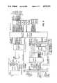
- FIG. 1is a block diagram illustrating the hub, and, its interconnection to an Ethernet coaxial cable through a H4000 transceiver, its eight BNC connectors and an external bus for intra hub interconnects.
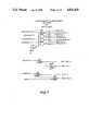
- FIG. 2is a state machine flow diagram illustrating the timing of information packets during transmission through the hub.
- FIG. 3is an output state machine flow diagram illustrating the output control ports on the hub.
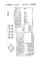
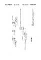
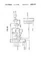
- FIG. 4is a circuit diagram illustrating the hub, interface ports, Ethernet interface port, fiber optic interface ports, intra-hub interconnect, power supply, indicators and switches.
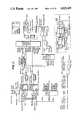
- FIG. 5Ais a circuit diagram illustrating the clock and buffer, error LED's and buffers and FIG. 5B is a circuit diagram illustrating the indicators and switches.
- FIG. 6is a circuit diagram illustrating the interface, the Ethernet transceiver interface and the fiber optic interface.
- FIG. 7is a circuit diagram of the intra repeater interconnect, buffers and receivers.
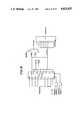
- FIG. 8is a block diagram of the hub functional partition.
- FIG. 9is a diagram illustrating a cluster of hubs coupled together in a daisy-chain fashion and a diagram of the intra repeater interconnect cable.
- the hubis a self-contained unit requiring AC power and having 8 BNC style connectors for eight ports.
- the unithas two other ports, one 15-pin female "D" for the connection of up to 8 hubs in a daisy-chain fashion.
- the 9-pin portis the intra repeater interconnect for the hub and provides for intra hub connection.
- the 8 BNC connectors and the transceiver connectionwill hereinafter be referred to as "ports”.
- the intra repeater interconnectwill hereinafter be referred to as the IRI.
- the hubtreats all of the ports and the IRI as a common data bus via a gate array that will perform all of the arbitration for the usage of the ports.
- the joining of the portscreates a larger Ethernet.
- the hubis not an Ethernet addressable unit on the network. It passes all data that is received on any one port to all other ports and the IRI.
- the unithas a 32-bit buffer for regeneration of the preamble of the received packets.
- An optional fiber optic interconnectis provided so that the hub can be used in harsh environments or for electrical isolation.
- the moduleis installed in a 30-pin vertical connector and a cover on the rear panel is removed.
- AC poweris provided to the unit via a single standard (3-prong), IEC connector.
- the AC poweris not switched to prevent the accidental loss of power to the unit.
- the unit when powered downexhibits no load at any of the ports. It does however disable the daisy-chain if the IRI is in use. (A jumper cable will be provided if the IRI is in use and a unit is being repaired.)
- the hubis used to expand the topology of the system in accordance with the invention to the much larger Ethernet and connect up to 64 ports with the IRI to the Ethernet via a single transceiver interconnection.
- the hubrestores the noise and timing margins as signals are propagated through the unit to the other ports attached to the hub.
- the passing of data from one port to eight other portsis not a simple switching task.
- the timing differences of the portsrequire the buffering of the received data in a FIFO fashion. Collisions on any port on the network need to be passed on to all of the other ports and the IRI.
- the data that is receivedis decoded via a single chip Manchester encoder/decoder, wherein the data and the clock are separated for usage in the gate array. All packets that are received will have the 64-bit preamble restored as it is repeated to the other ports.
- a receiveis detected on one of the ports.
- a preambleis sent to all of the other 8 ports and the IRI.
- IdleThere are four major states to the repeater process: Idle, Repeat, Collision and Wait. These 4 states are the basis of the global state machine and determine the state of the hub. The next state transition terms, such as IR (idle to repeat) are then defined in terms of the inputs to the state machine and determine when the state machine should transition from one state to another. The global state machine determines whether the hub is idle, repeating a packet or jamming a port if there is a collision.
- IRinle to repeat
- the transmission to each portis controlled by a one-bit XMIT state machine.
- the global present state and the global next state terms and other inputsdetermine whether the XMIT bit should be on or off.
- the one-bit state machines along with the global state machinesatisfy all the transition terms of the 802 spec.
- FIGS. 2 and 3illustrate the hub state machine and the output state machine, respectfully.
- the followingis a set of equations and signed definitions which control the flow of data to the ports of the hub.
- the current state of the hubis controlled by the received and collision inputs from all of the ports.
- Each of the portsare monitored by the state machine and transitions are determined by the condition of the inputs.
- the ic transitionoccurs whenever there is at least one collision anywhere in the system or whenever there are two or more simultaneous carriers from the 9 spurs.
- the ir transitionoccurs whenever there is only one carrier detected from the 9 spurs or when there is an IRI carrier and no local carrier and there are no collisions in the system.
- the wi transitionoccurs if the wait timer (GO) has timed out or in 802 mode and there is a collision in the system.
- the rc transitionoccurs whenever there is any collision in the system or if there are no collisions and carrier drops on the receive port and 64 bits of preamble and EOP have not been sent or 96 bits have not been sent and the FIFO buffer is empty.
- the rw transitionoccurs if there are no collisions in the system and the FIFO is empty or the jabber timer has timed out.
- the cw transitionoccurs if there are no collisions in the system and the receive port goes inactive and 96 bits have been sent and the carrier recovery timer has timed out. Note that COLXEN asserted implies no collisions.
- Output idleis combinational, and is asserted in idle state
- the bitis set if in the idle state there are multiple collisions detected on the IRI or on the 9 spurs, or if in the repeat state and a collision is detected on a spur that is transmitting or there are multiple collisions detected on the IRI, or in the collision state and the bit was set and the counter is not finished or the jamall condition still exists or there is a collision on a spur that is transmitting.
- Activeis a combinational output
- XMIT bit NThe XMIT bit will be turned on from the idle state if the ir transition is true and there is carrier from one of the 9 spurs and it is not its own spur or there is carrier from only the IRI, or if in the repeat state and the XMIT bit is already on and the global machine will remain in repeat state, i.e.
- the repeat to wait and the repeat to collision transitionsare not true, or if in the repeat state and the repeat to collision transition is true and a single collision occurs on one of the 8 other spurs, or a collision occurs only on the IRI (multiple or single) or a collision occurs on a spur that is transmitting, or in the idle state and the idle to collision transition is true and there is one collision and it is not our own port or there is a collision on the IRI or there is more than one collision on the 9 spurs or there is more than one carrier on the 9 spurs, or in the collision state and remaining there (i.e.
- All timing for the hubis generated from a 20.00-MHz 0.01% oscillator. This clock is used for timing of the gate array and the transmit data. Reference is made to FIGS. 4-8 which illustrate the construction of the hub.
- the major data path of the hubis via the transceiver chip from the BNC connector to the serial interface adapter (SIA) and from there to the gate array.
- the SIAperforms all of the decoding of the Manchester data and the separation of the data and clocking signals. At this point the data is multiplexed to the proper data path.
- the datais then buffered in the FIFO fashion.
- a 32-bit bufferoperating on a first-in/first-out basis, is employed for buffering the data that is received from any one of the ports.
- the FIFO bufferis used to allow for speed differences within the network. It holds the data until the entire 64-bit preamble is regenerated and sent to the eight transmitting ports.
- the decoding of the datais performed in the SIA chip.
- the encoding of the data to Manchester format on transmissionis also performed by the SIA chip.
- Jitteris defined as the edge to edge difference in the received encoded data.
- the hubreplicates the data of a receive if the preamble is less than 256 bits and more than 40 bits long. If these error conditions occur the FIFO may be underrun on a longer preamble and overrun on a shorter preamble. The hub will always transmit at least 63 bits of preamble.
- the hubbuffers all data from any port that is a valid packet in the FIFO buffer as the data bits are received.
- the FIFOis checked for the end of preamble (EOP) bits. This signifies the start of valid data bits in the received packet.
- EOPpreamble
- the FIFOdelays the unloading of the received bits from the FIFO until the regenerated preamble is completed.
- the hubUpon detection of 63 bits of regenerated preamble being sent and without having detected the EOP, the hub begins the output of data from the FIFO. This action will cause the addition of extra bits of preamble due to the additional bits of preamble in the FIFO.
- the hubcan detect the "11" or "00” pattern as the EOP. If no EOP is detected as in the above case, the hub will pass the data bits with the regenerated preamble as close to that of the receive.
- segmentationincreases the availability of the network.
- segmentationincreases the availability of the network.
- the segmentation of a circuitis performed when a fault is detected on a port of the hub.
- the faulty linecontinues to receive and transmits are attempted to verify that the port is still faulty.
- This mode of operation on this port of the hubis known as "segmentation" or the removal of this port from active usage.
- the hubwill reconnect a "segmented" port of the unit when a receive is completed with no errors.
- An error-free receiveis one with no collision detected and at least 512 bits of data.
- the hubsegments a port on the following conditions:
- a counteris incremented on each port for each successive collision of the hub and if this count reaches 64 the port is segmented.
- the counteris reset on each non-collided transmission.
- the hubdoes not receive a loopback of the transmitted data within a specified loop time.
- run pocketsAnother problem which may occur is defined as "runt pockets".
- the hubOn transmission to a port the hub will transmit at least 96 bits of data for any received. This is to ensure that fragments are long enough for all parties to detect the presence of the collision. This is to make certain that a collision with a runt packet (not legal length) is sent through the hub. The hub will add bits to received signals that are not 96 bits long. This is done until 96 bits are transmitted.
- the hubis designed so that the unit has a completely functional self-test. There are two ways of placing the unit into the self-test mode. These are:
- the unithas two distinct types of self-test for isolating various faults on the unit. These are an internal self-test and an external self-test.
- the internal self-testis run. This is run for one complete cycle of the 9 ports of the gate array and each is passed to a packet containing 256 bits of preamble and 1792 bits of data (l's). The data is looped internal to the gate array in the internal FIFO and compared. The collision counters and the segmentation of each port are checked before completion of the internal self-test. On the detection of an error on a port, this is indicated by error LEDs that are dedicated to each of the 9 ports.
- the external self-testis activated by the pressing of the reset button on the rear of the unit. This test will be run after the internal test has been completed.
- the external testloops a packet of 256 bits of preamble and 1792 bits of data (l's) and compares the looped packet. Each of the 8 BNC ports is tested and also the Ethernet port. The test also checks for the loss of carrier and the loopback capability of the transceiver chips.
- the hubis capable of running the internal self-test in a continuous mode when the LoopOnTest jumper is installed. This mode is run until the reset button is sensed and the hub runs one more pass of self-test and enters a mode of continuous external self-test. These are diagnostic features for burning the units and for service personnel. The jumper for this is accessable to the user without opening the enclosure.
- a collision presence testis performed after the transmit of a good packet to all of the ports externally. On the detection of the completion of the transmission, the collision presence test will generate a burst of 6 transitions at the normal 10-MHz rate. The hub checks to make certain that this short burst of data occurs after an external transmit on each port. After the external part of the self-test is completed, the generation of the collision presence test is disabled on all of the ports. This is a function that is only performed during the self-test. The transceiver heartbeat is disabled after completion of the self-test.
- the number of hubs that can be attached to the coaxis a maximum of two.
- the second connectionwill be the backup path to the Ethernet coax.
- the second unitmust have the "standby" switch in the standby position.
- the primary hubmust be in the "active” switch position. All of the remaining hub units of the daisy chain can be set to any mode (standby/active). These units will segment the Ethernet transceiver port due to a lack of loopback path.
- the primary hubwill be replaced by the standby unit if the standby unit records a predetermined number of valid packets that are not repeated to the Ethernet port. Only one of the hubs on any given Ethernet cluster can be the primary unit.
- the hubcan be configured to operate in compliance with an 802.3 jumperover time of 1.0 ⁇ sec and 96-bit preamble.
- the unitcan do this automatically on the first transmit after self-test. A test is performed to see if the heartbeat is within the 3.2 ⁇ sec window. This will then assume 802.3 operation if the heartbeat is not present. The jumper for 802.3 is removed to prevent the test from occurring.
- FIG. 9illustrates how a cluster of hubs are coupled together.
- Each hubhas an IRI port which serves as the interconnect point between the hubs.
- An IRI cableis employed for coupling the hubs together in a daisy-chain fashion.
- the IRI cablehas two ends, wherein one end has a male connector for coupling into the IRI port on the hub and the other end has both a male and a female connector, wherein the male connector is for coupling to an IRI port on another hub, and the female connector is for coupling to another IRI cable.
- the followingis a description of the signals on each of the pins illustrated in FIG. 9:
- the IRIis to be used when the need for more than one hub is required and the user does not wish to install an additional transceiver.
- the additional hubsare connected via the 9-pin D type connector.
- the termination of the cablecan be made by placing a termination connector at the far end of the connected units. All of the hubs monitor a common bus for the following signals: carrier, receiveclock, receivedata and collision. These are the "OR" of the 8 channels of the respective signals.
- an activity signalis passed from each unit for the indication of the completion of jams.
Landscapes
- Engineering & Computer Science (AREA)
- Computer Networks & Wireless Communication (AREA)
- Signal Processing (AREA)
- Small-Scale Networks (AREA)
- Communication Cables (AREA)
- Cable Transmission Systems, Equalization Of Radio And Reduction Of Echo (AREA)
- Electrical Discharge Machining, Electrochemical Machining, And Combined Machining (AREA)
- Windings For Motors And Generators (AREA)
- Sorption Type Refrigeration Machines (AREA)
- Medicines That Contain Protein Lipid Enzymes And Other Medicines (AREA)
- Radio Relay Systems (AREA)
Abstract
Description
______________________________________ INPUTS ACTIVE, JW output of state flip-flops JABBER indicates that 48K bits have been transmitted COLXEN carrier recovery time up and 96 bits sent and no collisions XMITALL all XMIT bits are on RCOLGT1 more than one IRI collision (IRI Jam All) RCOMCAR common carrier from IRI RANYCOL any collision on the IRI (RCOLEQ1 + RCOLGT1) FIFO -EMPTY no carrier from receive port and all data sent JAM -START output of jam -start flip flop JAM -DONE output of jam timer GO wait state (heartbeat) timer done XMITCOL XMITO*COLO *...XMIT8*COL*8 SYNC RESET synchronous reset careq0 no local carrier careq1 single local carrier cargt1 multiple local carriers coleq0 no local collisions coleq1 single local collision colgt1 more than one local collision RCVCAR carrier drops on the receive port SEL802 IEEE 802.3 select EOP64 end of preamble and 64 bits sent OUTPUTS next -state1, next -state0 input to state flip-flops JAM in collision state ACTIVE active IDLE in idle state JAM -START -INPUT input to jam -start flip-flop IC,IR RC,RW,CW transition outputs for XMITN machines IFIELD state = ACTIVE,JW OFIELD next -state = next -state1, next -state0 BIND idle -state = state/00 this state assignment collision -state = state/11 produces fewer terms wait -state = state/01 than several others... repeat -state = state/10 idle -next -state = next -state/00 this state assignment collision -next -state = next -state/11 produces fewer terms wait -next -state = next -state/01 than several others... repeat -next -state = next -state/10 anycol = (-coleq0 + RANYCOL) jamall = (RCOLGT1 + colgt1) ______________________________________
ic=(-SYNC.sub.-- RESET*(anycol+cargt1))
ir=(-SYNC.sub.-- RESET*((careq1+RCOMCAR* careq0)*(-anycol)))
wi=(GO+SYNC.sub.-- RESET+SEL802*(anycol))
rc=(-SYNC.sub.-- RESET*(anycol+-anycol*-RCVCAR & *(-EPO64+-COLXEN*EOP64*FIFO.sub.-- EMPTY)))
rw=(-SYNC.sub.-- RESET*((COLXEN*-anycol*FIFO.sub.-- EMPTY)+JABBER))
cw=(-SYNC.sub.-- RESET*(COLXEN*-RCVCAR*(-JAM.sub.-- START+JAM.sub.-- START*JAM.sub.-- DONE) & +JABBER))
__________________________________________________________________________JAM -START -INPUT = idle -state * -SYNC -RESET * (jamall + cargt1) & + repeat -state * -SYNC -RESET * (RCOLGT1 + XMITCOL) & + collision -state * & SYNC -RESET*((JAM -START * -JAM -DONE) + jamall __________________________________________________________________________
______________________________________ idle -next -state = wait -state * (wi) & + collision -state * SYNC -RESET & + repeat -state * SYNC -RESET & + (idle -state * -(ic + ir)) ______________________________________
______________________________________ collision -next -state = idle -state * ic & + repeat -state * rc & + collision -state * (-cw) ______________________________________
______________________________________ wait -next -state = repeat -state * rw & + collision -state * cw & + wait -state * -wi ______________________________________
______________________________________ repeat -next -state = idle -state * ir & + repeat -state * -(rc + rw) ______________________________________
______________________________________ INPUTS ACTIVE, JW output of state flip-flops SYNC -COLN collision from port N, synchronized and not segmented SYNC -CARN carrier from port N, synchronized and not segmented XMITCOL XMITO*COLO+...+XMIT8*COL8 XMITN output of XMIT flip-flop N JAM -START output of jam start flip-flop JAM -DONE output of jam counter RCOLGT1 IRI jam all RCOMCAR carrier on IRI RANYCOL any collision of IRI careq0 no local carrier careq1 single local carrier cargt1 multiple local carriers dlycoleq0 no local collisions delay by a tick coleq0 no local collisions coleq1 single local collision colgt1 more than one local collision IR,IC,CW,RW,RC transition terms from global machine OUTPUTS NXT -XMITN input to XMIT flip-flop N IFIELD state = ACTIVE, JW state bits of global machine BIND states of global machine idle -state = state/00 collision -state = state/11 wait -stat = state/01 repeat -state = state/10 iricol = (dlycoleq0 * RANYCOL) collision on IRI only anycol = (-coleq0 + RANYCOL) collision anywhere jamall = (RCOLGT1 + colgt1) multiple collisions on IRI, locally, or both ______________________________________
Claims (9)
Priority Applications (12)
| Application Number | Priority Date | Filing Date | Title |
|---|---|---|---|
| US06/796,470US4825435A (en) | 1985-11-08 | 1985-11-08 | Multiport repeater |
| MX004275AMX167433B (en) | 1985-11-08 | 1986-11-06 | METHOD AND APPARATUS TO TRANSMIT AN INFORMATION PACK |
| IL80553AIL80553A (en) | 1985-11-08 | 1986-11-07 | Thin-wire multiport repeater |
| AU64948/86AAU591193B2 (en) | 1985-11-08 | 1986-11-07 | Thin-wise multiport repeater |
| DE3689535TDE3689535T2 (en) | 1985-11-08 | 1986-11-07 | Thin-wire multiple-point intermediate regenerator. |
| JP61264127AJPH0671261B2 (en) | 1985-11-08 | 1986-11-07 | Multi-port repeater |
| AT86402498TATE100260T1 (en) | 1985-11-08 | 1986-11-07 | THIN WIRE MULTI-JOT INTERMEDIATE REGEN. |
| FI864536AFI91583C (en) | 1985-11-08 | 1986-11-07 | Global local area network |
| CA000522513ACA1279115C (en) | 1985-11-08 | 1986-11-07 | Thin-wire multiport repeater |
| EP86402498AEP0222669B1 (en) | 1985-11-08 | 1986-11-07 | Thin-wire multiport repeater |
| KR1019860009470AKR950002267B1 (en) | 1985-11-08 | 1986-11-08 | Thin Line Multiport Repeater |
| CN86107753ACN1009894B (en) | 1985-11-08 | 1986-11-08 | Slimline Multiport Repeater |
Applications Claiming Priority (1)
| Application Number | Priority Date | Filing Date | Title |
|---|---|---|---|
| US06/796,470US4825435A (en) | 1985-11-08 | 1985-11-08 | Multiport repeater |
Publications (1)
| Publication Number | Publication Date |
|---|---|
| US4825435Atrue US4825435A (en) | 1989-04-25 |
Family
ID=25168264
Family Applications (1)
| Application Number | Title | Priority Date | Filing Date |
|---|---|---|---|
| US06/796,470Expired - LifetimeUS4825435A (en) | 1985-11-08 | 1985-11-08 | Multiport repeater |
Country Status (12)
| Country | Link |
|---|---|
| US (1) | US4825435A (en) |
| EP (1) | EP0222669B1 (en) |
| JP (1) | JPH0671261B2 (en) |
| KR (1) | KR950002267B1 (en) |
| CN (1) | CN1009894B (en) |
| AT (1) | ATE100260T1 (en) |
| AU (1) | AU591193B2 (en) |
| CA (1) | CA1279115C (en) |
| DE (1) | DE3689535T2 (en) |
| FI (1) | FI91583C (en) |
| IL (1) | IL80553A (en) |
| MX (1) | MX167433B (en) |
Cited By (69)
| Publication number | Priority date | Publication date | Assignee | Title |
|---|---|---|---|---|
| US5179554A (en)* | 1991-04-08 | 1993-01-12 | Digital Equipment Corporation | Automatic association of local area network station addresses with a repeater port |
| US5265124A (en)* | 1990-02-15 | 1993-11-23 | Advanced Micro Devices, Inc. | Integrated multi-port repeater having shared resources |
| US5293375A (en)* | 1991-01-18 | 1994-03-08 | National Semiconductor Corporation | Repeater interface controller with a partitioning port state machine |
| US5296936A (en)* | 1991-07-22 | 1994-03-22 | International Business Machines Corporation | Communication apparatus and method for transferring image data from a source to one or more receivers |
| US5315590A (en)* | 1990-02-15 | 1994-05-24 | Advanced Micro Devices Inc. | Selectable repeater port reconnection method and apparatus |
| US5339307A (en)* | 1991-06-28 | 1994-08-16 | Digital Equipment Corporation | Data communication system with a local network interface |
| US5341363A (en)* | 1991-05-10 | 1994-08-23 | Kabushiki Kaisha Toshiba | Computer system capable of disconnecting itself from a lan |
| US5355375A (en)* | 1993-03-18 | 1994-10-11 | Network Systems Corporation | Hub controller for providing deterministic access to CSMA local area network |
| US5400360A (en)* | 1993-03-23 | 1995-03-21 | Limitorque Corporation | Repeater for a digital control system |
| US5432907A (en)* | 1992-05-12 | 1995-07-11 | Network Resources Corporation | Network hub with integrated bridge |
| US5467351A (en)* | 1994-04-22 | 1995-11-14 | At&T Corp. | Extendible round robin local area hub network |
| US5469438A (en)* | 1994-01-28 | 1995-11-21 | At&T Ipm Corp. | Method of transmitting signals in an extendible local area network |
| US5471472A (en)* | 1991-07-30 | 1995-11-28 | Synernetics Inc. | Network multiplexer |
| WO1997004547A1 (en)* | 1995-07-18 | 1997-02-06 | Macronix America, Inc. | Expandable integrated circuit multiport repeater controller with multiple media independent interfaces and mixed media connections |
| US5608729A (en)* | 1995-04-20 | 1997-03-04 | Lucent Technologies Inc. | Method and apparatus for providing two-way data communication cover a widely distributed network |
| US5617418A (en)* | 1992-11-02 | 1997-04-01 | National Semiconductor Corporation | Network link detection and generation |
| US5621893A (en)* | 1994-11-22 | 1997-04-15 | Lucent Technologies Inc. | System for expanding ports wherein segment switch selectively associates plurality of hubs coupled to first arbiter and plurality of hubs coupled to second arbiter |
| US5629685A (en)* | 1995-02-23 | 1997-05-13 | International Business Machines Corporation | Segmentable addressable modular communication network hubs |
| US5666359A (en)* | 1995-07-12 | 1997-09-09 | Compaq Computer Corp. | Method and apparatus for displaying port information |
| US5666488A (en)* | 1994-11-22 | 1997-09-09 | Lucent Technologies Inc. | Port expansion network and method for lAN hubs |
| US5680113A (en)* | 1995-02-24 | 1997-10-21 | International Business Machines Corporation | Dynamic address assignments to serially connected devices |
| US5720032A (en)* | 1992-05-12 | 1998-02-17 | Compaq Computer Corporation | Network packet switch using shared memory for repeating and bridging packets at media rate |
| US5796738A (en)* | 1995-03-13 | 1998-08-18 | Compaq Computer Corporation | Multiport repeater with collision detection and jam signal generation |
| US5805597A (en)* | 1996-06-04 | 1998-09-08 | National Semiconductor Corporation | Method and apparatus for providing low power basic telephony type service over a twisted pair ethernet physical layer |
| US5870566A (en)* | 1994-11-22 | 1999-02-09 | Lucent Technologies, Inc. | Port expansion network and method for lan hubs |
| US5896508A (en)* | 1995-02-23 | 1999-04-20 | Advanced Micro Devices, Inc. | Hub-network adapter device for a file server personal computer |
| US6041061A (en)* | 1997-01-31 | 2000-03-21 | Macronix International Co., Ltd. | Internal arbiter for a repeater in a computer network |
| AU720165B2 (en)* | 1996-07-12 | 2000-05-25 | Cais, Inc. | Digital communication system for apartment buildings and similar structures using existing telephone wires |
| US6181783B1 (en) | 1989-07-14 | 2001-01-30 | Inline Connection Corporation | Data and telephone wiring terminal |
| US6236718B1 (en) | 1989-07-14 | 2001-05-22 | Inline Connections Corporation | Video transmission and control system utilizing internal telephone lines |
| US6243446B1 (en) | 1997-03-11 | 2001-06-05 | Inline Connections Corporation | Distributed splitter for data transmission over twisted wire pairs |
| US6243510B1 (en) | 2000-03-13 | 2001-06-05 | Apcon, Inc. | Electronically-controllable fiber optic patch panel |
| US20040125819A1 (en)* | 2001-07-05 | 2004-07-01 | Yehuda Binder | Telephone outlet with packet telephony adapter, and a network using same |
| US20040199909A1 (en)* | 1999-07-27 | 2004-10-07 | Inline Connection Corporation | Universal serial bus adapter with automatic installation |
| US20040230710A1 (en)* | 1999-07-27 | 2004-11-18 | Inline Connection Corporation | System and method of automatic installation of computer peripherals |
| USRE38820E1 (en) | 1994-12-21 | 2005-10-11 | Negotiated Data Solutions Llc | Multi-protocol packet framing over an isochronous network |
| US20050249245A1 (en)* | 2004-05-06 | 2005-11-10 | Serconet Ltd. | System and method for carrying a wireless based signal over wiring |
| US20050277328A1 (en)* | 2000-04-19 | 2005-12-15 | Serconet Ltd | Network combining wired and non-wired segments |
| USRE39116E1 (en)* | 1992-11-02 | 2006-06-06 | Negotiated Data Solutions Llc | Network link detection and generation |
| USRE39216E1 (en) | 1992-11-02 | 2006-08-01 | Negotiated Data Solutions Llc | Asynchronous processor access to a switch table in a network with isochronous capability |
| USRE39395E1 (en) | 1992-11-02 | 2006-11-14 | Negotiated Data Solutions Llc | Data communication network with transfer port, cascade port and/or frame synchronizing signal |
| US7145990B2 (en) | 1999-06-11 | 2006-12-05 | Inline Connection Corporation | High-speed data communication over a residential telephone wiring network |
| US20070173202A1 (en)* | 2006-01-11 | 2007-07-26 | Serconet Ltd. | Apparatus and method for frequency shifting of a wireless signal and systems using frequency shifting |
| US7275050B2 (en)* | 2001-05-25 | 2007-09-25 | Hitachi, Ltd. | Storage system, a method of file data backup and method of copying of file data |
| US7274688B2 (en) | 2000-04-18 | 2007-09-25 | Serconet Ltd. | Telephone communication system over a single telephone line |
| US7317793B2 (en) | 2003-01-30 | 2008-01-08 | Serconet Ltd | Method and system for providing DC power on local telephone lines |
| US7436842B2 (en) | 2001-10-11 | 2008-10-14 | Serconet Ltd. | Outlet with analog signal adapter, a method for use thereof and a network using said outlet |
| US7483524B2 (en) | 1999-07-20 | 2009-01-27 | Serconet, Ltd | Network for telephony and data communication |
| US7522714B2 (en) | 2000-03-20 | 2009-04-21 | Serconet Ltd. | Telephone outlet for implementing a local area network over telephone lines and a local area network using such outlets |
| US7686653B2 (en) | 2003-09-07 | 2010-03-30 | Mosaid Technologies Incorporated | Modular outlet |
| US7873058B2 (en) | 2004-11-08 | 2011-01-18 | Mosaid Technologies Incorporated | Outlet with analog signal adapter, a method for use thereof and a network using said outlet |
| US8175649B2 (en) | 2008-06-20 | 2012-05-08 | Corning Mobileaccess Ltd | Method and system for real time control of an active antenna over a distributed antenna system |
| US8238328B2 (en) | 2003-03-13 | 2012-08-07 | Mosaid Technologies Incorporated | Telephone system having multiple distinct sources and accessories therefor |
| US8270430B2 (en) | 1998-07-28 | 2012-09-18 | Mosaid Technologies Incorporated | Local area network of serial intelligent cells |
| US8594133B2 (en) | 2007-10-22 | 2013-11-26 | Corning Mobileaccess Ltd. | Communication system using low bandwidth wires |
| US8750903B1 (en) | 2012-02-28 | 2014-06-10 | CellAntenna Corporation | Cell phone control and localization for restricted facilities |
| US8897215B2 (en) | 2009-02-08 | 2014-11-25 | Corning Optical Communications Wireless Ltd | Communication system using cables carrying ethernet signals |
| US9184960B1 (en) | 2014-09-25 | 2015-11-10 | Corning Optical Communications Wireless Ltd | Frequency shifting a communications signal(s) in a multi-frequency distributed antenna system (DAS) to avoid or reduce frequency interference |
| US9338823B2 (en) | 2012-03-23 | 2016-05-10 | Corning Optical Communications Wireless Ltd | Radio-frequency integrated circuit (RFIC) chip(s) for providing distributed antenna system functionalities, and related components, systems, and methods |
| US9529360B1 (en) | 2015-01-28 | 2016-12-27 | Howard Melamed | System and method for detecting and defeating a drone |
| WO2017136166A1 (en)* | 2016-02-04 | 2017-08-10 | TEN DIGIT Communications LLC | Intermediary device for data message network routing and enhancement in a contact center environment |
| US9797978B1 (en) | 2014-09-03 | 2017-10-24 | Howard Melamed | UAV, system, and method for radio frequency spectral analysis |
| US9847035B1 (en) | 2015-01-28 | 2017-12-19 | Howard Melamed | Methods for radio frequency spectral analysis |
| US10367766B2 (en) | 2017-01-20 | 2019-07-30 | TEN DIGIT Communications LLC | Intermediary device for data message network routing |
| US10739451B1 (en) | 2014-12-19 | 2020-08-11 | Xidrone Systems, Inc. | Systems and methods for detecting, tracking and identifying small unmanned systems such as drones |
| US10907940B1 (en) | 2017-12-12 | 2021-02-02 | Xidrone Systems, Inc. | Deterrent for unmanned aerial systems using data mining and/or machine learning for improved target detection and classification |
| US10986165B2 (en) | 2004-01-13 | 2021-04-20 | May Patents Ltd. | Information device |
| US11035929B2 (en) | 2014-12-19 | 2021-06-15 | Xidrone Systems, Inc. | Deterrent for unmanned aerial systems |
| US11277251B1 (en) | 2019-07-03 | 2022-03-15 | Michael Patrick Millard | Radio frequency spectrum management system and method |
Families Citing this family (9)
| Publication number | Priority date | Publication date | Assignee | Title |
|---|---|---|---|---|
| US5265123A (en)* | 1990-02-15 | 1993-11-23 | Advanced Micro Devices, Inc. | Expandable repeater |
| CA2056262A1 (en)* | 1990-12-31 | 1992-07-01 | William L. Aranguren | Intrusion detection apparatus for local area network |
| GB9107031D0 (en)* | 1991-04-04 | 1991-05-22 | Bicc Plc | Repeaters for digital data networks |
| GB9201126D0 (en)* | 1992-01-20 | 1992-03-11 | Madge Networks Ltd | Communication system |
| US5455700A (en)* | 1992-04-30 | 1995-10-03 | Fisher Controls International, Inc. | Regenerative communication channel extender |
| FR2726954B1 (en)* | 1994-11-15 | 1997-01-24 | Dassault Electronique | RELAY UNIT BETWEEN STATION AND COMMUNICATION CHANNEL, PARTICULARLY FOR ETHERNET NETWORKS |
| US5799041A (en)* | 1996-02-05 | 1998-08-25 | Xinex Networks Inc. | Network for multimedia asynchronous transfer mode digital signal transmission and components thereof |
| US5878221A (en)* | 1996-02-05 | 1999-03-02 | Xinex Networks Inc. | Network for multimedia asynchronous transfer mode digital signal transmission and components thereof |
| KR100284485B1 (en)* | 1998-06-15 | 2001-03-15 | 신승영 | LAN card |
Citations (10)
| Publication number | Priority date | Publication date | Assignee | Title |
|---|---|---|---|---|
| US3889064A (en)* | 1974-03-27 | 1975-06-10 | Nasa | Asynchronous, multiplexing, single line transmission and recovery data system |
| US4228535A (en)* | 1979-02-26 | 1980-10-14 | Rockwell International Corporation | Dual TDM switching apparatus |
| US4334306A (en)* | 1978-06-02 | 1982-06-08 | Texas Instruments Incorporated | Transparent intelligent network for data and voice |
| US4347498A (en)* | 1979-11-21 | 1982-08-31 | International Business Machines Corporation | Method and means for demand accessing and broadcast transmission among ports in a distributed star network |
| US4399531A (en)* | 1980-09-29 | 1983-08-16 | Rockwell International Corporation | Distributed digital data communications network |
| US4417334A (en)* | 1981-04-16 | 1983-11-22 | Ncr Corporation | Data processing system having dual-channel system bus |
| US4425662A (en)* | 1980-03-18 | 1984-01-10 | Telecommunications Radioelectriques Et Telephoniques T.R.T. | System for tele-locating regenerative repeaters |
| US4597079A (en)* | 1983-03-16 | 1986-06-24 | Fujitsu Limited | Redundant switchover system for TDMA satellite communication equipment |
| US4598399A (en)* | 1984-11-20 | 1986-07-01 | Rockwell International Corporation | Multichannel multisite signal protection channel switching apparatus |
| US4646361A (en)* | 1983-03-10 | 1987-02-24 | Nec Corporation | Optical star repeater |
Family Cites Families (6)
| Publication number | Priority date | Publication date | Assignee | Title |
|---|---|---|---|---|
| US4034470A (en)* | 1974-10-11 | 1977-07-12 | Amp Incorporated | Method for fabricating multi-conductor tap connector |
| US4472712A (en)* | 1982-03-05 | 1984-09-18 | At&T Bell Laboratories | Multipoint data communication system with local arbitration |
| DE3306942A1 (en)* | 1983-02-28 | 1984-08-30 | Siemens AG, 1000 Berlin und 8000 München | ARRANGEMENT FOR THE TRANSFER OF DATA BETWEEN A DATA PROCESSING SYSTEM AND MULTIPLE DATA FACILITIES IN THE LOCAL AREA OVER DETERMINED INTERFACES |
| US4491968A (en)* | 1983-04-07 | 1985-01-01 | Comsonics, Inc. | Status monitor |
| US4556974A (en)* | 1983-10-07 | 1985-12-03 | Honeywell Inc. | Method for passing a token in a local-area network |
| US4706081A (en)* | 1984-12-14 | 1987-11-10 | Vitalink Communications Corporation | Method and apparatus for bridging local area networks |
- 1985
- 1985-11-08USUS06/796,470patent/US4825435A/ennot_activeExpired - Lifetime
- 1986
- 1986-11-06MXMX004275Apatent/MX167433B/enunknown
- 1986-11-07FIFI864536Apatent/FI91583C/ennot_activeIP Right Cessation
- 1986-11-07JPJP61264127Apatent/JPH0671261B2/ennot_activeExpired - Lifetime
- 1986-11-07ATAT86402498Tpatent/ATE100260T1/ennot_activeIP Right Cessation
- 1986-11-07DEDE3689535Tpatent/DE3689535T2/ennot_activeExpired - Fee Related
- 1986-11-07ILIL80553Apatent/IL80553A/enunknown
- 1986-11-07CACA000522513Apatent/CA1279115C/ennot_activeExpired - Fee Related
- 1986-11-07EPEP86402498Apatent/EP0222669B1/ennot_activeExpired - Lifetime
- 1986-11-07AUAU64948/86Apatent/AU591193B2/ennot_activeCeased
- 1986-11-08KRKR1019860009470Apatent/KR950002267B1/ennot_activeExpired - Fee Related
- 1986-11-08CNCN86107753Apatent/CN1009894B/ennot_activeExpired
Patent Citations (10)
| Publication number | Priority date | Publication date | Assignee | Title |
|---|---|---|---|---|
| US3889064A (en)* | 1974-03-27 | 1975-06-10 | Nasa | Asynchronous, multiplexing, single line transmission and recovery data system |
| US4334306A (en)* | 1978-06-02 | 1982-06-08 | Texas Instruments Incorporated | Transparent intelligent network for data and voice |
| US4228535A (en)* | 1979-02-26 | 1980-10-14 | Rockwell International Corporation | Dual TDM switching apparatus |
| US4347498A (en)* | 1979-11-21 | 1982-08-31 | International Business Machines Corporation | Method and means for demand accessing and broadcast transmission among ports in a distributed star network |
| US4425662A (en)* | 1980-03-18 | 1984-01-10 | Telecommunications Radioelectriques Et Telephoniques T.R.T. | System for tele-locating regenerative repeaters |
| US4399531A (en)* | 1980-09-29 | 1983-08-16 | Rockwell International Corporation | Distributed digital data communications network |
| US4417334A (en)* | 1981-04-16 | 1983-11-22 | Ncr Corporation | Data processing system having dual-channel system bus |
| US4646361A (en)* | 1983-03-10 | 1987-02-24 | Nec Corporation | Optical star repeater |
| US4597079A (en)* | 1983-03-16 | 1986-06-24 | Fujitsu Limited | Redundant switchover system for TDMA satellite communication equipment |
| US4598399A (en)* | 1984-11-20 | 1986-07-01 | Rockwell International Corporation | Multichannel multisite signal protection channel switching apparatus |
Cited By (162)
| Publication number | Priority date | Publication date | Assignee | Title |
|---|---|---|---|---|
| US6542585B2 (en) | 1989-07-14 | 2003-04-01 | Inline Connection Corporation | Distributed splitter for data transmission over twisted wire pairs |
| US6236718B1 (en) | 1989-07-14 | 2001-05-22 | Inline Connections Corporation | Video transmission and control system utilizing internal telephone lines |
| US6185284B1 (en) | 1989-07-14 | 2001-02-06 | Inline Connections Corporation | Voice and data transmission over twisted wire pairs |
| US6181783B1 (en) | 1989-07-14 | 2001-01-30 | Inline Connection Corporation | Data and telephone wiring terminal |
| US20020071531A1 (en)* | 1989-07-14 | 2002-06-13 | Inline Connections Corporation, A Virginia Corporation | Video transmission and control system utilizing internal telephone lines |
| US7227932B2 (en) | 1989-07-14 | 2007-06-05 | Inline Connection Corporation | Multi-band data over voice communication system and method |
| US7224780B2 (en) | 1989-07-14 | 2007-05-29 | Inline Connection Corporation | Multichannel transceiver using redundant encoding and strategic channel spacing |
| US20050117722A1 (en)* | 1989-07-14 | 2005-06-02 | Inline Connection Corporation | Video transmission and control system utilizing internal telephone lines |
| US7577240B2 (en) | 1989-07-14 | 2009-08-18 | Inline Connection Corporation | Two-way communication over a single transmission line between one or more information sources and a group of telephones, computers, and televisions |
| US20050117721A1 (en)* | 1989-07-14 | 2005-06-02 | Goodman David D. | Video transmission and control system utilizing internal telephone lines |
| US20030165220A1 (en)* | 1989-07-14 | 2003-09-04 | Goodman David D. | Distributed splitter for data transmission over twisted wire pairs |
| US6970537B2 (en) | 1989-07-14 | 2005-11-29 | Inline Connection Corporation | Video transmission and control system utilizing internal telephone lines |
| US7149289B2 (en) | 1989-07-14 | 2006-12-12 | Inline Connection Corporation | Interactive data over voice communication system and method |
| US5265124A (en)* | 1990-02-15 | 1993-11-23 | Advanced Micro Devices, Inc. | Integrated multi-port repeater having shared resources |
| US5315590A (en)* | 1990-02-15 | 1994-05-24 | Advanced Micro Devices Inc. | Selectable repeater port reconnection method and apparatus |
| US5396495A (en)* | 1991-01-18 | 1995-03-07 | National Semiconductor Corporation | Hub management bus architecture for repeater interface controller |
| US5430726A (en)* | 1991-01-18 | 1995-07-04 | Moorwood; Charles A. | Repeater interface controller with a shared data bus |
| US5293375A (en)* | 1991-01-18 | 1994-03-08 | National Semiconductor Corporation | Repeater interface controller with a partitioning port state machine |
| US5299195A (en)* | 1991-01-18 | 1994-03-29 | National Semiconductor Corporation | Repeater interface controller with multiple port node interfaces |
| US5384767A (en)* | 1991-01-18 | 1995-01-24 | National Semiconductor Corporation | Segment tester for a repeater interface controller |
| US5179554A (en)* | 1991-04-08 | 1993-01-12 | Digital Equipment Corporation | Automatic association of local area network station addresses with a repeater port |
| US5341363A (en)* | 1991-05-10 | 1994-08-23 | Kabushiki Kaisha Toshiba | Computer system capable of disconnecting itself from a lan |
| US5339307A (en)* | 1991-06-28 | 1994-08-16 | Digital Equipment Corporation | Data communication system with a local network interface |
| US5296936A (en)* | 1991-07-22 | 1994-03-22 | International Business Machines Corporation | Communication apparatus and method for transferring image data from a source to one or more receivers |
| US5657314A (en)* | 1991-07-30 | 1997-08-12 | 3Com Corporation | Network multiplexer |
| US5471472A (en)* | 1991-07-30 | 1995-11-28 | Synernetics Inc. | Network multiplexer |
| US20080284840A1 (en)* | 1991-12-05 | 2008-11-20 | Inline Connection Corporation | Method, System and Apparatus for Voice and Data Transmission Over A Conductive Path |
| US5432907A (en)* | 1992-05-12 | 1995-07-11 | Network Resources Corporation | Network hub with integrated bridge |
| US5737525A (en)* | 1992-05-12 | 1998-04-07 | Compaq Computer Corporation | Network packet switch using shared memory for repeating and bridging packets at media rate |
| US5742760A (en)* | 1992-05-12 | 1998-04-21 | Compaq Computer Corporation | Network packet switch using shared memory for repeating and bridging packets at media rate |
| US5720032A (en)* | 1992-05-12 | 1998-02-17 | Compaq Computer Corporation | Network packet switch using shared memory for repeating and bridging packets at media rate |
| USRE39395E1 (en) | 1992-11-02 | 2006-11-14 | Negotiated Data Solutions Llc | Data communication network with transfer port, cascade port and/or frame synchronizing signal |
| USRE39216E1 (en) | 1992-11-02 | 2006-08-01 | Negotiated Data Solutions Llc | Asynchronous processor access to a switch table in a network with isochronous capability |
| USRE39116E1 (en)* | 1992-11-02 | 2006-06-06 | Negotiated Data Solutions Llc | Network link detection and generation |
| USRE39405E1 (en)* | 1992-11-02 | 2006-11-21 | Negotiated Data Solutions Llc | Network link endpoint capability detection |
| US5617418A (en)* | 1992-11-02 | 1997-04-01 | National Semiconductor Corporation | Network link detection and generation |
| US5687174A (en)* | 1992-11-02 | 1997-11-11 | National Semiconductor Corporation | Network link endpoint capability detection |
| US5355375A (en)* | 1993-03-18 | 1994-10-11 | Network Systems Corporation | Hub controller for providing deterministic access to CSMA local area network |
| US5400360A (en)* | 1993-03-23 | 1995-03-21 | Limitorque Corporation | Repeater for a digital control system |
| US5469438A (en)* | 1994-01-28 | 1995-11-21 | At&T Ipm Corp. | Method of transmitting signals in an extendible local area network |
| US5467351A (en)* | 1994-04-22 | 1995-11-14 | At&T Corp. | Extendible round robin local area hub network |
| US5621893A (en)* | 1994-11-22 | 1997-04-15 | Lucent Technologies Inc. | System for expanding ports wherein segment switch selectively associates plurality of hubs coupled to first arbiter and plurality of hubs coupled to second arbiter |
| US5870566A (en)* | 1994-11-22 | 1999-02-09 | Lucent Technologies, Inc. | Port expansion network and method for lan hubs |
| US5666488A (en)* | 1994-11-22 | 1997-09-09 | Lucent Technologies Inc. | Port expansion network and method for lAN hubs |
| USRE38820E1 (en) | 1994-12-21 | 2005-10-11 | Negotiated Data Solutions Llc | Multi-protocol packet framing over an isochronous network |
| US5896508A (en)* | 1995-02-23 | 1999-04-20 | Advanced Micro Devices, Inc. | Hub-network adapter device for a file server personal computer |
| US5629685A (en)* | 1995-02-23 | 1997-05-13 | International Business Machines Corporation | Segmentable addressable modular communication network hubs |
| US5680113A (en)* | 1995-02-24 | 1997-10-21 | International Business Machines Corporation | Dynamic address assignments to serially connected devices |
| US5796738A (en)* | 1995-03-13 | 1998-08-18 | Compaq Computer Corporation | Multiport repeater with collision detection and jam signal generation |
| US5854790A (en)* | 1995-03-13 | 1998-12-29 | Compaq Computer Corp. | Method and apparatus for networking data devices using an uplink module |
| US5608729A (en)* | 1995-04-20 | 1997-03-04 | Lucent Technologies Inc. | Method and apparatus for providing two-way data communication cover a widely distributed network |
| US5666359A (en)* | 1995-07-12 | 1997-09-09 | Compaq Computer Corp. | Method and apparatus for displaying port information |
| US5742602A (en)* | 1995-07-12 | 1998-04-21 | Compaq Computer Corporation | Adaptive repeater system |
| WO1997004547A1 (en)* | 1995-07-18 | 1997-02-06 | Macronix America, Inc. | Expandable integrated circuit multiport repeater controller with multiple media independent interfaces and mixed media connections |
| US5754540A (en)* | 1995-07-18 | 1998-05-19 | Macronix International Co., Ltd. | Expandable integrated circuit multiport repeater controller with multiple media independent interfaces and mixed media connections |
| US5805597A (en)* | 1996-06-04 | 1998-09-08 | National Semiconductor Corporation | Method and apparatus for providing low power basic telephony type service over a twisted pair ethernet physical layer |
| AU720165B2 (en)* | 1996-07-12 | 2000-05-25 | Cais, Inc. | Digital communication system for apartment buildings and similar structures using existing telephone wires |
| US6041061A (en)* | 1997-01-31 | 2000-03-21 | Macronix International Co., Ltd. | Internal arbiter for a repeater in a computer network |
| US6243446B1 (en) | 1997-03-11 | 2001-06-05 | Inline Connections Corporation | Distributed splitter for data transmission over twisted wire pairs |
| US8325636B2 (en) | 1998-07-28 | 2012-12-04 | Mosaid Technologies Incorporated | Local area network of serial intelligent cells |
| US8885659B2 (en) | 1998-07-28 | 2014-11-11 | Conversant Intellectual Property Management Incorporated | Local area network of serial intelligent cells |
| US8908673B2 (en) | 1998-07-28 | 2014-12-09 | Conversant Intellectual Property Management Incorporated | Local area network of serial intelligent cells |
| US8270430B2 (en) | 1998-07-28 | 2012-09-18 | Mosaid Technologies Incorporated | Local area network of serial intelligent cells |
| US8885660B2 (en) | 1998-07-28 | 2014-11-11 | Conversant Intellectual Property Management Incorporated | Local area network of serial intelligent cells |
| US8867523B2 (en) | 1998-07-28 | 2014-10-21 | Conversant Intellectual Property Management Incorporated | Local area network of serial intelligent cells |
| US7145990B2 (en) | 1999-06-11 | 2006-12-05 | Inline Connection Corporation | High-speed data communication over a residential telephone wiring network |
| US8351582B2 (en) | 1999-07-20 | 2013-01-08 | Mosaid Technologies Incorporated | Network for telephony and data communication |
| US8929523B2 (en) | 1999-07-20 | 2015-01-06 | Conversant Intellectual Property Management Inc. | Network for telephony and data communication |
| US7483524B2 (en) | 1999-07-20 | 2009-01-27 | Serconet, Ltd | Network for telephony and data communication |
| US7492875B2 (en) | 1999-07-20 | 2009-02-17 | Serconet, Ltd. | Network for telephony and data communication |
| US7522713B2 (en) | 1999-07-20 | 2009-04-21 | Serconet, Ltd. | Network for telephony and data communication |
| US20040199909A1 (en)* | 1999-07-27 | 2004-10-07 | Inline Connection Corporation | Universal serial bus adapter with automatic installation |
| US20040230710A1 (en)* | 1999-07-27 | 2004-11-18 | Inline Connection Corporation | System and method of automatic installation of computer peripherals |
| US6243510B1 (en) | 2000-03-13 | 2001-06-05 | Apcon, Inc. | Electronically-controllable fiber optic patch panel |
| US8363797B2 (en) | 2000-03-20 | 2013-01-29 | Mosaid Technologies Incorporated | Telephone outlet for implementing a local area network over telephone lines and a local area network using such outlets |
| US8855277B2 (en) | 2000-03-20 | 2014-10-07 | Conversant Intellectual Property Managment Incorporated | Telephone outlet for implementing a local area network over telephone lines and a local area network using such outlets |
| US7715534B2 (en) | 2000-03-20 | 2010-05-11 | Mosaid Technologies Incorporated | Telephone outlet for implementing a local area network over telephone lines and a local area network using such outlets |
| US7522714B2 (en) | 2000-03-20 | 2009-04-21 | Serconet Ltd. | Telephone outlet for implementing a local area network over telephone lines and a local area network using such outlets |
| US7593394B2 (en) | 2000-04-18 | 2009-09-22 | Mosaid Technologies Incorporated | Telephone communication system over a single telephone line |
| US7274688B2 (en) | 2000-04-18 | 2007-09-25 | Serconet Ltd. | Telephone communication system over a single telephone line |
| US8000349B2 (en) | 2000-04-18 | 2011-08-16 | Mosaid Technologies Incorporated | Telephone communication system over a single telephone line |
| US7466722B2 (en) | 2000-04-18 | 2008-12-16 | Serconet Ltd | Telephone communication system over a single telephone line |
| US7397791B2 (en) | 2000-04-18 | 2008-07-08 | Serconet, Ltd. | Telephone communication system over a single telephone line |
| US8223800B2 (en) | 2000-04-18 | 2012-07-17 | Mosaid Technologies Incorporated | Telephone communication system over a single telephone line |
| US8559422B2 (en) | 2000-04-18 | 2013-10-15 | Mosaid Technologies Incorporated | Telephone communication system over a single telephone line |
| US8867506B2 (en) | 2000-04-19 | 2014-10-21 | Conversant Intellectual Property Management Incorporated | Network combining wired and non-wired segments |
| US8848725B2 (en) | 2000-04-19 | 2014-09-30 | Conversant Intellectual Property Management Incorporated | Network combining wired and non-wired segments |
| US20050277328A1 (en)* | 2000-04-19 | 2005-12-15 | Serconet Ltd | Network combining wired and non-wired segments |
| US8873586B2 (en) | 2000-04-19 | 2014-10-28 | Conversant Intellectual Property Management Incorporated | Network combining wired and non-wired segments |
| US8873575B2 (en) | 2000-04-19 | 2014-10-28 | Conversant Intellectual Property Management Incorporated | Network combining wired and non-wired segments |
| US7633966B2 (en) | 2000-04-19 | 2009-12-15 | Mosaid Technologies Incorporated | Network combining wired and non-wired segments |
| US8982904B2 (en) | 2000-04-19 | 2015-03-17 | Conversant Intellectual Property Management Inc. | Network combining wired and non-wired segments |
| US7275050B2 (en)* | 2001-05-25 | 2007-09-25 | Hitachi, Ltd. | Storage system, a method of file data backup and method of copying of file data |
| US20080209144A1 (en)* | 2001-05-25 | 2008-08-28 | Hitachi, Ltd. | Storage system, a method of file data back up and a method of copying of file data |
| US8341199B2 (en) | 2001-05-25 | 2012-12-25 | Hitachi, Ltd. | Storage system, a method of file data back up and a method of copying of file data |
| US20040125819A1 (en)* | 2001-07-05 | 2004-07-01 | Yehuda Binder | Telephone outlet with packet telephony adapter, and a network using same |
| US8761186B2 (en) | 2001-07-05 | 2014-06-24 | Conversant Intellectual Property Management Incorporated | Telephone outlet with packet telephony adapter, and a network using same |
| US7769030B2 (en) | 2001-07-05 | 2010-08-03 | Mosaid Technologies Incorporated | Telephone outlet with packet telephony adapter, and a network using same |
| US8472593B2 (en) | 2001-07-05 | 2013-06-25 | Mosaid Technologies Incorporated | Telephone outlet with packet telephony adaptor, and a network using same |
| US7680255B2 (en) | 2001-07-05 | 2010-03-16 | Mosaid Technologies Incorporated | Telephone outlet with packet telephony adaptor, and a network using same |
| US7542554B2 (en) | 2001-07-05 | 2009-06-02 | Serconet, Ltd | Telephone outlet with packet telephony adapter, and a network using same |
| US7453895B2 (en) | 2001-10-11 | 2008-11-18 | Serconet Ltd | Outlet with analog signal adapter, a method for use thereof and a network using said outlet |
| US7436842B2 (en) | 2001-10-11 | 2008-10-14 | Serconet Ltd. | Outlet with analog signal adapter, a method for use thereof and a network using said outlet |
| US7953071B2 (en) | 2001-10-11 | 2011-05-31 | Mosaid Technologies Incorporated | Outlet with analog signal adapter, a method for use thereof and a network using said outlet |
| US7889720B2 (en) | 2001-10-11 | 2011-02-15 | Mosaid Technologies Incorporated | Outlet with analog signal adapter, a method for use thereof and a network using said outlet |
| US7860084B2 (en) | 2001-10-11 | 2010-12-28 | Mosaid Technologies Incorporated | Outlet with analog signal adapter, a method for use thereof and a network using said outlet |
| US8787562B2 (en) | 2003-01-30 | 2014-07-22 | Conversant Intellectual Property Management Inc. | Method and system for providing DC power on local telephone lines |
| US8107618B2 (en) | 2003-01-30 | 2012-01-31 | Mosaid Technologies Incorporated | Method and system for providing DC power on local telephone lines |
| US7317793B2 (en) | 2003-01-30 | 2008-01-08 | Serconet Ltd | Method and system for providing DC power on local telephone lines |
| US7702095B2 (en) | 2003-01-30 | 2010-04-20 | Mosaid Technologies Incorporated | Method and system for providing DC power on local telephone lines |
| US8238328B2 (en) | 2003-03-13 | 2012-08-07 | Mosaid Technologies Incorporated | Telephone system having multiple distinct sources and accessories therefor |
| US7867035B2 (en) | 2003-07-09 | 2011-01-11 | Mosaid Technologies Incorporated | Modular outlet |
| US8092258B2 (en) | 2003-09-07 | 2012-01-10 | Mosaid Technologies Incorporated | Modular outlet |
| US8591264B2 (en) | 2003-09-07 | 2013-11-26 | Mosaid Technologies Incorporated | Modular outlet |
| US7686653B2 (en) | 2003-09-07 | 2010-03-30 | Mosaid Technologies Incorporated | Modular outlet |
| US8360810B2 (en) | 2003-09-07 | 2013-01-29 | Mosaid Technologies Incorporated | Modular outlet |
| US8235755B2 (en) | 2003-09-07 | 2012-08-07 | Mosaid Technologies Incorporated | Modular outlet |
| US10986164B2 (en) | 2004-01-13 | 2021-04-20 | May Patents Ltd. | Information device |
| US11032353B2 (en) | 2004-01-13 | 2021-06-08 | May Patents Ltd. | Information device |
| US11095708B2 (en) | 2004-01-13 | 2021-08-17 | May Patents Ltd. | Information device |
| US10986165B2 (en) | 2004-01-13 | 2021-04-20 | May Patents Ltd. | Information device |
| US20050249245A1 (en)* | 2004-05-06 | 2005-11-10 | Serconet Ltd. | System and method for carrying a wireless based signal over wiring |
| US8325759B2 (en) | 2004-05-06 | 2012-12-04 | Corning Mobileaccess Ltd | System and method for carrying a wireless based signal over wiring |
| US7873058B2 (en) | 2004-11-08 | 2011-01-18 | Mosaid Technologies Incorporated | Outlet with analog signal adapter, a method for use thereof and a network using said outlet |
| US8184681B2 (en) | 2006-01-11 | 2012-05-22 | Corning Mobileaccess Ltd | Apparatus and method for frequency shifting of a wireless signal and systems using frequency shifting |
| US7813451B2 (en) | 2006-01-11 | 2010-10-12 | Mobileaccess Networks Ltd. | Apparatus and method for frequency shifting of a wireless signal and systems using frequency shifting |
| US7587001B2 (en) | 2006-01-11 | 2009-09-08 | Serconet Ltd. | Apparatus and method for frequency shifting of a wireless signal and systems using frequency shifting |
| US20070173202A1 (en)* | 2006-01-11 | 2007-07-26 | Serconet Ltd. | Apparatus and method for frequency shifting of a wireless signal and systems using frequency shifting |
| US8594133B2 (en) | 2007-10-22 | 2013-11-26 | Corning Mobileaccess Ltd. | Communication system using low bandwidth wires |
| US9813229B2 (en) | 2007-10-22 | 2017-11-07 | Corning Optical Communications Wireless Ltd | Communication system using low bandwidth wires |
| US9549301B2 (en) | 2007-12-17 | 2017-01-17 | Corning Optical Communications Wireless Ltd | Method and system for real time control of an active antenna over a distributed antenna system |
| US8175649B2 (en) | 2008-06-20 | 2012-05-08 | Corning Mobileaccess Ltd | Method and system for real time control of an active antenna over a distributed antenna system |
| US8897215B2 (en) | 2009-02-08 | 2014-11-25 | Corning Optical Communications Wireless Ltd | Communication system using cables carrying ethernet signals |
| US8750903B1 (en) | 2012-02-28 | 2014-06-10 | CellAntenna Corporation | Cell phone control and localization for restricted facilities |
| US9338823B2 (en) | 2012-03-23 | 2016-05-10 | Corning Optical Communications Wireless Ltd | Radio-frequency integrated circuit (RFIC) chip(s) for providing distributed antenna system functionalities, and related components, systems, and methods |
| US9948329B2 (en) | 2012-03-23 | 2018-04-17 | Corning Optical Communications Wireless, LTD | Radio-frequency integrated circuit (RFIC) chip(s) for providing distributed antenna system functionalities, and related components, systems, and methods |
| US10141959B2 (en) | 2012-03-23 | 2018-11-27 | Corning Optical Communications Wireless Ltd | Radio-frequency integrated circuit (RFIC) chip(s) for providing distributed antenna system functionalities, and related components, systems, and methods |
| US9797978B1 (en) | 2014-09-03 | 2017-10-24 | Howard Melamed | UAV, system, and method for radio frequency spectral analysis |
| US9515855B2 (en) | 2014-09-25 | 2016-12-06 | Corning Optical Communications Wireless Ltd | Frequency shifting a communications signal(s) in a multi-frequency distributed antenna system (DAS) to avoid or reduce frequency interference |
| US9184960B1 (en) | 2014-09-25 | 2015-11-10 | Corning Optical Communications Wireless Ltd | Frequency shifting a communications signal(s) in a multi-frequency distributed antenna system (DAS) to avoid or reduce frequency interference |
| US9253003B1 (en) | 2014-09-25 | 2016-02-02 | Corning Optical Communications Wireless Ltd | Frequency shifting a communications signal(S) in a multi-frequency distributed antenna system (DAS) to avoid or reduce frequency interference |
| US10739451B1 (en) | 2014-12-19 | 2020-08-11 | Xidrone Systems, Inc. | Systems and methods for detecting, tracking and identifying small unmanned systems such as drones |
| US11035929B2 (en) | 2014-12-19 | 2021-06-15 | Xidrone Systems, Inc. | Deterrent for unmanned aerial systems |
| US12298378B2 (en) | 2014-12-19 | 2025-05-13 | Xidrone Systems, Inc. | Counter unmanned aerial system with navigation data to Intercept and/or disable an unmanned aerial vehicle threat |
| US11156707B2 (en) | 2014-12-19 | 2021-10-26 | Xidrone Systems, Inc. | Systems and methods for detecting, tracking and identifying small unmanned systems such as drones |
| US10795010B2 (en) | 2014-12-19 | 2020-10-06 | Xidrone Systems, Inc. | Systems and methods for detecting, tracking and identifying small unmanned systems such as drones |
| US12092756B1 (en) | 2014-12-19 | 2024-09-17 | Xidrone Systems, Inc. | Deterrent for unmanned aerial systems |
| US11644535B2 (en) | 2014-12-19 | 2023-05-09 | Xidrone Systems, Inc. | Deterrent for unmanned aerial systems |
| US11378651B2 (en) | 2014-12-19 | 2022-07-05 | Xidrone Systems, Inc. | Deterrent for unmanned aerial systems |
| US11965977B2 (en) | 2014-12-19 | 2024-04-23 | Xidrone Systems, Inc. | Deterrent for unmanned aerial systems |
| US10234857B1 (en) | 2015-01-28 | 2019-03-19 | Cellantenna International Inc. | System and method for detecting and defeating a drone |
| US9529360B1 (en) | 2015-01-28 | 2016-12-27 | Howard Melamed | System and method for detecting and defeating a drone |
| US10374732B1 (en) | 2015-01-28 | 2019-08-06 | Howard Melamed | Methods for radio frequency spectral analysis |
| US10915099B1 (en) | 2015-01-28 | 2021-02-09 | Cellantenna International Inc. | System and method for detecting and defeating a drone |
| US9847035B1 (en) | 2015-01-28 | 2017-12-19 | Howard Melamed | Methods for radio frequency spectral analysis |
| WO2017136166A1 (en)* | 2016-02-04 | 2017-08-10 | TEN DIGIT Communications LLC | Intermediary device for data message network routing and enhancement in a contact center environment |
| US11431847B2 (en) | 2016-02-04 | 2022-08-30 | Virtual Hold Technology Solutions, Llc | Intermediary device for data message network routing and enhancement in a contact center environment |
| US10455090B2 (en) | 2016-02-04 | 2019-10-22 | TEN DIGIT Communications LLC | Intermediary device for data message network routing and enhancement in a contact center environment |
| US11146517B2 (en) | 2017-01-20 | 2021-10-12 | Virtual Hold Technology Solutions, Llc | Intermediary device for data message network routing |
| US10367766B2 (en) | 2017-01-20 | 2019-07-30 | TEN DIGIT Communications LLC | Intermediary device for data message network routing |
| US10907940B1 (en) | 2017-12-12 | 2021-02-02 | Xidrone Systems, Inc. | Deterrent for unmanned aerial systems using data mining and/or machine learning for improved target detection and classification |
| US11277251B1 (en) | 2019-07-03 | 2022-03-15 | Michael Patrick Millard | Radio frequency spectrum management system and method |
Also Published As
| Publication number | Publication date |
|---|---|
| CA1279115C (en) | 1991-01-15 |
| FI864536L (en) | 1987-05-09 |
| MX167433B (en) | 1993-03-22 |
| KR950002267B1 (en) | 1995-03-15 |
| AU6494886A (en) | 1987-05-14 |
| JPS62271539A (en) | 1987-11-25 |
| EP0222669B1 (en) | 1994-01-12 |
| JPH0671261B2 (en) | 1994-09-07 |
| IL80553A0 (en) | 1987-02-27 |
| FI864536A0 (en) | 1986-11-07 |
| CN86107753A (en) | 1987-09-23 |
| CN1009894B (en) | 1990-10-03 |
| EP0222669A2 (en) | 1987-05-20 |
| ATE100260T1 (en) | 1994-01-15 |
| FI91583B (en) | 1994-03-31 |
| IL80553A (en) | 1991-03-10 |
| EP0222669A3 (en) | 1989-02-22 |
| KR870005522A (en) | 1987-06-09 |
| DE3689535D1 (en) | 1994-02-24 |
| AU591193B2 (en) | 1989-11-30 |
| FI91583C (en) | 1994-07-11 |
| DE3689535T2 (en) | 1994-07-28 |
Similar Documents
| Publication | Publication Date | Title |
|---|---|---|
| US4825435A (en) | Multiport repeater | |
| US4951280A (en) | Method and apparatus for configuring data paths within a supernet station | |
| JP2909084B2 (en) | Run communication device and media adapter used for it | |
| US5249183A (en) | Interfacing unit for local area networks | |
| US6928086B2 (en) | Dynamic detection of LAN network protocol | |
| EP0495575B1 (en) | Repeater interface controller | |
| Rufino et al. | A Columbus' egg idea for CAN media redundancy | |
| US5680113A (en) | Dynamic address assignments to serially connected devices | |
| Ross | Rings are'round for good! | |
| US6920520B2 (en) | Methods and circuits for stacking bus architecture | |
| US5671249A (en) | Inter-repeater backplane with synchronous/asynchronous dual mode operation | |
| US5508998A (en) | Remote token ring beacon station detection and isolation | |
| US5309435A (en) | Multiring data transmission system | |
| US6240101B1 (en) | Bi-directional daisy-chain cascading of network repeaters | |
| Hopper et al. | Design and use of an integrated Cambridge ring | |
| US5777996A (en) | Inter-repeater backplane for allowing hot-swapping of individual repeater circuits | |
| Rufino | Dual-media redundancy mechanisms for CAN | |
| GB2218599A (en) | Local access network signel regenerator | |
| EP0230116B1 (en) | Tdm ring communication medium | |
| Rufino | Redundant CAN architectures for dependable communication | |
| CA2325936C (en) | Bus architecture for high reliability communications in a computer system | |
| Henderson et al. | Options for campus fiber networks | |
| JPS6276839A (en) | Data transfer control system | |
| Saltzer | DIFFERENCES BETWEEN THE IBM RESEARCH Z-RING AND THE LCS VERSION TWO RING | |
| JPH0719213B2 (en) | Online test method for disperser |
Legal Events
| Date | Code | Title | Description |
|---|---|---|---|
| AS | Assignment | Owner name:DIGITAL EQUIPMENT CORPORATION, 146 MAIN STREET, MA Free format text:ASSIGNMENT OF ASSIGNORS INTEREST.;ASSIGNORS:AMUNDSEN, KEITH B.;EVANS, RICHARD P.;FREISS, RICHARD C.;AND OTHERS;REEL/FRAME:004625/0816;SIGNING DATES FROM 19860324 TO 19860331 | |
| STCF | Information on status: patent grant | Free format text:PATENTED CASE | |
| FEPP | Fee payment procedure | Free format text:PAYOR NUMBER ASSIGNED (ORIGINAL EVENT CODE: ASPN); ENTITY STATUS OF PATENT OWNER: LARGE ENTITY | |
| FPAY | Fee payment | Year of fee payment:4 | |
| FPAY | Fee payment | Year of fee payment:8 | |
| AS | Assignment | Owner name:CABLETRON SYSTEMS, INC., NEW HAMPSHIRE Free format text:ASSIGNMENT OF ASSIGNORS INTEREST;ASSIGNOR:DIGITAL EQUIPMENT CORPORATION;REEL/FRAME:009046/0792 Effective date:19980206 | |
| FEPP | Fee payment procedure | Free format text:PAYOR NUMBER ASSIGNED (ORIGINAL EVENT CODE: ASPN); ENTITY STATUS OF PATENT OWNER: LARGE ENTITY Free format text:PAYER NUMBER DE-ASSIGNED (ORIGINAL EVENT CODE: RMPN); ENTITY STATUS OF PATENT OWNER: LARGE ENTITY | |
| FPAY | Fee payment | Year of fee payment:12 | |
| AS | Assignment | Owner name:ENTERASYS NETWORKS, INC., NEW HAMPSHIRE Free format text:ASSIGNMENT OF ASSIGNORS INTEREST;ASSIGNOR:CABLETRON SYSTEMS, INC.;REEL/FRAME:011219/0376 Effective date:20000929 | |
| AS | Assignment | Owner name:WELLS FARGO FOOTHILL, INC., CALIFORNIA Free format text:SECURITY AGREEMENT;ASSIGNOR:ENTERASYS NETWORKS, INC.;REEL/FRAME:017656/0552 Effective date:20060516 Owner name:OBSIDIAN, LLC, CALIFORNIA Free format text:SECURITY AGREEMENT;ASSIGNOR:ENTERASYS NETWORKS, INC.;REEL/FRAME:017656/0552 Effective date:20060516 | |
| AS | Assignment | Owner name:ENTERASYS NETWORKS, INC., MASSACHUSETTS Free format text:RELEASE AND REASSIGNMENT OF PATENTS AND PATENT APPLICATIONS AT REEL/FRAME NO. 17656/0552;ASSIGNORS:WELLS FARGO CAPITAL FINANCE, INC. (FORMERLY KNOWN AS WELLS FARGO FOOTHILL, INC.);ENTERPRISE COMMUNICATIONS FUNDING GMBH, AS SUCCESSOR IN INTEREST TO OBSIDIAN, LLC;REEL/FRAME:025406/0769 Effective date:20101110 |