US4825263A - Optical method and apparatus for determining three-dimensional changes in facial contours - Google Patents
Optical method and apparatus for determining three-dimensional changes in facial contoursDownload PDFInfo
- Publication number
- US4825263A US4825263AUS07/057,577US5757787AUS4825263AUS 4825263 AUS4825263 AUS 4825263AUS 5757787 AUS5757787 AUS 5757787AUS 4825263 AUS4825263 AUS 4825263A
- Authority
- US
- United States
- Prior art keywords
- intersection points
- video signal
- grid representation
- grid
- curvatures
- Prior art date
- Legal status (The legal status is an assumption and is not a legal conclusion. Google has not performed a legal analysis and makes no representation as to the accuracy of the status listed.)
- Expired - Lifetime
Links
Images


Classifications
- G—PHYSICS
- G01—MEASURING; TESTING
- G01B—MEASURING LENGTH, THICKNESS OR SIMILAR LINEAR DIMENSIONS; MEASURING ANGLES; MEASURING AREAS; MEASURING IRREGULARITIES OF SURFACES OR CONTOURS
- G01B11/00—Measuring arrangements characterised by the use of optical techniques
- G01B11/24—Measuring arrangements characterised by the use of optical techniques for measuring contours or curvatures
- A—HUMAN NECESSITIES
- A61—MEDICAL OR VETERINARY SCIENCE; HYGIENE
- A61B—DIAGNOSIS; SURGERY; IDENTIFICATION
- A61B5/00—Measuring for diagnostic purposes; Identification of persons
- A61B5/103—Measuring devices for testing the shape, pattern, colour, size or movement of the body or parts thereof, for diagnostic purposes
- A61B5/107—Measuring physical dimensions, e.g. size of the entire body or parts thereof
- A61B5/1079—Measuring physical dimensions, e.g. size of the entire body or parts thereof using optical or photographic means
- G—PHYSICS
- G01—MEASURING; TESTING
- G01B—MEASURING LENGTH, THICKNESS OR SIMILAR LINEAR DIMENSIONS; MEASURING ANGLES; MEASURING AREAS; MEASURING IRREGULARITIES OF SURFACES OR CONTOURS
- G01B11/00—Measuring arrangements characterised by the use of optical techniques
- G01B11/16—Measuring arrangements characterised by the use of optical techniques for measuring the deformation in a solid, e.g. optical strain gauge
- G01B11/167—Measuring arrangements characterised by the use of optical techniques for measuring the deformation in a solid, e.g. optical strain gauge by projecting a pattern on the object
- G—PHYSICS
- G01—MEASURING; TESTING
- G01B—MEASURING LENGTH, THICKNESS OR SIMILAR LINEAR DIMENSIONS; MEASURING ANGLES; MEASURING AREAS; MEASURING IRREGULARITIES OF SURFACES OR CONTOURS
- G01B11/00—Measuring arrangements characterised by the use of optical techniques
- G01B11/24—Measuring arrangements characterised by the use of optical techniques for measuring contours or curvatures
- G01B11/25—Measuring arrangements characterised by the use of optical techniques for measuring contours or curvatures by projecting a pattern, e.g. one or more lines, moiré fringes on the object
- G01B11/2513—Measuring arrangements characterised by the use of optical techniques for measuring contours or curvatures by projecting a pattern, e.g. one or more lines, moiré fringes on the object with several lines being projected in more than one direction, e.g. grids, patterns
- G—PHYSICS
- G06—COMPUTING OR CALCULATING; COUNTING
- G06T—IMAGE DATA PROCESSING OR GENERATION, IN GENERAL
- G06T7/00—Image analysis
- G06T7/50—Depth or shape recovery
- G06T7/521—Depth or shape recovery from laser ranging, e.g. using interferometry; from the projection of structured light
Definitions
- the following inventionrelates generally to a method and apparatus for determining three-dimensional changes in a surface, and more particularly, is directed to a method and apparatus for optically determining three-dimensional changes in facial contours due to swelling and the like.
- it is necessary to measure three-dimensional changes in facial contoursFor example, the surgical extraction of impacted wisdom teeth is followed almost invariably by some degree of post-operative swelling of the related soft tissues.
- Various anti-inflamatory drugshave been utilized for reducing such swelling. In order to assess the anti-inflamatory effects of these drugs, it is necessary 15 to measure the extent that the swelling is reduced over a period of time.
- one of the major difficulties in investigations of facial swellingis that of accurately measuring the swelling. With the measuring techniques utilized to date, pre-operative and post-operative measurements are taken and the results are compared to obtain an indication of the extent of swelling.
- one arm of a pair of callipersis placed in the interdental space between the mandibular first and second molars and the other arm of the callipers is placed in light contact with the external cheek surface.
- J. H. Sowray"An Assessment of the Value of Lyophilised Chymotrypsin in the Reduction of Post-Operative Swelling Following the Removal of Impacted Wisdom Teeth", British Dental Journal, Feb. 21, 1961, pgs. 130-133.
- utilization of callipersdoes not provide an accurate measurement of the extent of swelling since such measurement is taken at a single point on the cheek.
- the device of this latter articleconsists of 16 adjustable plastic screws, eight on each side of the face, on bilateral plates, which are fixed on a facial bow attached to an individual bite-block. The plastic screws are adjusted into touching contact with the skin and are adjusted at each sitting and then compared with pre-operative measurements to give an indication of swelling. However, again, with this device, only point measurements are taken.
- a method of optically mapping a three-dimensional surfaceincludes the steps of illuminating the surface through a grid structure to produce a grid representation on the suraface; viewing the illuminated surface with a video camera; producing a video signal in response to the step of viewing; converting the video signal to digital form; storing a frame of the digitized video signal in a frame memory; defining the grid representation on the surface from the stored video signal; locating coordinates of the intersection points of the grid representation; determining curvatures of the grid representation at the located intersection points; and three-dimensionally reconstructing the surface from the coordinates and curvatures of the intersection points.
- apparatus for optically mapping a three-dimensional surfaceincludes illumination means for illuminating the surface through a grid structure to produce a grid representation on the surface; video camera means for viewing the illuminated surface and for producing a video signal in response thereto; analog-to-digital converting means for converting the video signal to digital form; memory means for storing a frame of the digitized video signal in a frame memory; and central processing means for defining the grid representation on the surface from the stored video signal, for locating coordinates of the intersection points of the grid representation, for determining curvatures of the grid representation at the located intersection points, and for three-dimensionally reconstructing the surface from the coordinates and curvatures of the intersection points.
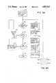
- FIG. 1is a schematic, block diagram of the overall apparatus for optically determining three-dimensional changes in facial contours according to the present invention
- FIG. 2is a schematic, top plan view of the mechanical portion of the apparatus of FIG. 1;
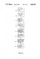
- FIG. 3is an overall flow chart diagram of the method of using the apparatus of FIG. 1;
- FIG. 4Ais a schematic diagram of a plurality of pixels and an imaginary box constructed therearound for isolating the grid representation
- FIG. 4Bis a flow chart diagram explaining how the grid representation on the person's face is defined
- FIG. 5Ais a schematic diagram of a plurality of pixels and an imaginary box constructed therearound used for locating intersection points of the grid representation;
- FIG. 5Bis a flow chart diagram showing the location of coordinates and the determination of curvatures of the intersection points of the grid representation
- FIG. 6Ais a schematic diagram of a plurality of pixels used for performing a three-dimensional construction in the area bounded by four intersection points;
- FIG. 6Bis flow chart diagram, showing how the face is three-dimensionally reconstructed from the coordinates and curvatures of the intersection points;
- FIG. 7is a graphical representation of volume change versus time, obtained with the present invention.
- FIG. 8is a schematic representation of the person's face, reconstructed with the present invention.
- apparatus 10 for optically measuring three-dimensional changes in facial contoursincludes a restraint device 12 of a conventional nature which restrains the person's head 14 from moving so as to provide a fixed reference thereof.
- An arm 16is attached to restraint device 12 for rotation about head 14, the free end of arm 16 having a support 18 secure perpendicularly thereto.
- a structured light source 20, such as an ordinary incandescent light bulb,is mounted to support 18 for illuminating face 14a of the patient.
- a translucent or transparent plate 22 having a grid structure 24 thereonis mounted in front of light source 20, and for example, can be secured to arm 16.
- plate 22can be a translucent plate having a grid structure 24 etched thereon, a photographic plate or the like.
- light rays from light source 20pass through plate 22 and illuminate the patient's face 14a. Because of grid structure 24, a grid pattern or representation 24 is projected on the patient's face 14a.
- a video camera 28is also mounted on support 18 as close as possible to light source 20 for viewing the illuminated patient's face 14a.
- light source 20 and video camera 28should be attached at the same point.
- the angle of incidence 30,that is, the angle made by the light travelling from light source 20 to the person's face 14a and then to video camera 28, is made as small as possible.
- the distance d between light source 20 and video camera 28is much smaller than the distance D from support 18 to the point of attachment of arm 16 to restraint device 12, as shown in FIG. 2.
- Video camera 28produces a resultant analog video signal which is supplied to a video monitor 32 for displaying the patient's head 14 and face 14a thereon. More importantly, the analog video signal is used for processing in accordance with the present invention to determine three-dimensional changes in facial contours.
- analog video signal from video camera 28is supplied to an analog-to-digital (A/D) converter 34 where it is converted to digital form.
- A/D converter 34is then supplied to a frame buffer 36 which stores one freeze frame of the video picture displayed on video monitor 32.
- the digitized video signal from frame buffer 36is then supplied to a central processing unit (CPU) 38 for further processing in accordance with appropriate software stored in a read only memory (ROM) 40 and instructions from a keyboard 42.
- ROMread only memory
- RAMrandom access memory
- FIG. 3an overall flow chart diagram which describes the different processes according to the present invention starts with illumination of face 14a with grid structure 24 to provide the aforementioned grid pattern 26, in step 46. Thereafter, face 14a is viewed with video camera 28 in step 48 and the video signal is then digitized and one frame thereof is stored in frame buffer 36, as indicated in step 50 of FIG. 3. It will be appreciated that the digitized video signal stored in frame buffer 36 includes information regarding the entire face, including grid pattern or representation 26 thereon. Accordingly, in step 52, it is necessary to isolate the grid pattern or representation 26 from the remainder of the video information, that is, to define only the grid representation on face 14a.
- step 54it is necessary to locate the coordinates of intersection points of grid representation 26, that is, the points where the horizontal and vertical lines of grid representation 26 intersect, and to thereafter determine curvatures of face 14a at such intersection points in step 56.
- step 58there is a three-dimensional reconstruction of face 14a from the coordinates of the intersection points of grid representation 26 and curvatures of face 14a at such points. Then, volumetric changes in the face due to, for example, swelling, are determined in step 59.
- FIG. 4Bthere is shown a flow chart diagram for defining grid representation 26 on face 14a.
- video informationis represented by a plurality of pixels.
- the step of defining grid representation 26 on face 14ais accomplished by using a median filter, whereby the values of light intensity in an imaginary box surrounding each pixel is subtracted from the light intensity value of the particular pixel which is surrounded thereby.
- an imaginary box 60is constructed around a center pixel 62.
- imaginary box 60can be constructed of a matrix of 3 ⁇ 3 pixels 64.
- the light intensity values of all of pixels 62 and 64 in imaginary box 60is determined, and these light intensity values are averaged to determine a median light intensity for imaginary box 60.
- This median light intensity valueis then subtracted from the actual light intensity value of center pixel 62 about which imaginary box 60 was constructed. This operation is performed for each pixel about which such a box 60 can be constructed, that is, practically speaking, 95% of all pixels on the video picture of face 14a, whereupon the resultant light intensity values define only grid representation or pattern 26 on face 14a.
- the first point or pixelis selected or initialized for processing in step 66.
- this pixelis generally selected in the second row of the second column of the video picture.
- the reason that the first row or the first column is not selectedis that a 3 ⁇ 3 matrix of pixels cannot be constructed about such a point.
- the order for determining the selection of pixelsstarts at the upper left corner of the video picture and moves rightwardly along each row. When the last pixel to be evaluated in each row is obtained, the process moves to the second column of the next lower row and so on until the last pixel at the lower right corner of the video picture is evaluated.
- step 68it is determined in step 68 whether this pixel is the last pixel to be evaluated in the row. If not, the process moves to step 70, where the process described in FIG. 4A is performed. Specifically, in step 70, imaginary box 60 is constructed about the selected pixel 62 and the median light intensity of the pixels in box 60 is determined and subtracted from the actual light intensity of the center pixel 62. Then, in step 72, this new value for center pixel 62 is stored in RAM 44 and the process moves to the next pixel, for example, pixel 62a shown in FIG. 4A. Then, the process moves back to step 68 to determine if this is the last pixel to be evaluated in the row, and so on.
- step 74it is determined whether the last row to be evaluated has been reached, which is the next to last row in the actual picture, since a 3 ⁇ 3 matrix of pixels must be able to be constructed about each pixel. If the last row to be evaluated is not yet obtained, the process moves to step 76 where evaluation is moved to the next lower row at column 2, and then back to step 68. In this manner, each of the pixels in the second row are evaluated one at a time, moving from left to right. Then, the pixels in the next lower row are evaluated, one at a time, moving from left to right, and so on until the last row to be evaluated is completed.
- step 78the process moves to step 78, whereby the resultant stored information of the median removed intensities corresponds to a map of the intensities of grid representation 26 only, whereupon this part of the process is stopped at step 80.
- the next step in the processis to locate the intersections of grid pattern 26, that is, where the horizontal and vertical lines of grid pattern 26 intersect. Specifically, if it is assumed that the horizontal and vertical grid lines of grid pattern 26 have an intensity of logic level "1" and all other points have an intensity of logicl level "0", it is only necessary to detect the pattern shown in FIG. 5A. In FIG. 5A, the intersection point is represented by numeral 82, that is, where the horizontal and vertical lines meet.
- all intersection points 82 of grid pattern 26are detected and the curvatures along the horizontal and vertical lines through such intersection points 82 are also determined.
- a maskis first defined in step 84.
- the maskcan be formed by constructing an imaginary box 86 about a 3 ⁇ 3 matrix of pixels of grid pattern 26 shown in FIG. 5A.
- the first pixel in such grid pattern 26 to be evaluatedis selected in step 87. In the same manner as was done in FIG.
- each pixel of grid pattern 26is evaluated, starting from the first selected pixel, which is the pixel in the second row, second column. Thereafter, the pixels are evaluated one at a time, moving rightwardly in the second row. It is then determined whether this is the last pixel to be evaluated in the row in step 88. If not, the process moves to step 90 where a logical AND operation is performed with the mask pattern defined within imaginary box 86 and an actual 3 ⁇ 3 matrix of pixels constructed around the pixel to be evaluated. If the logical AND operation produces a logic level "1" output, this indicates that the pixel to be evaluated is an intersection point and if the logical AND operation produces a logic level "0" output, this indicates that no intersection point has been found.
- each of the intersection points 82 of grid pattern or representation 26can be detected in steps 90 and 92 so that the coordinates of such intersection points are known.
- step 100the curvatures of the horizontal and vertical lines passing through the detected intersection point 82 are computed by numerically approximating the second derivatives along each direction at such intersection point 82. This is accomplished by using a sum and difference of the position of points, which is a well known procedure.
- the first derivative f 0' at the intersection point f 0is found and corresponds to the slope of the horizontal line passing through such intersection point f 0 .
- Thisis performed for each of the intersection points, that is, intersection points f 0 , f 1 , f 2 , f -1 , f -2 and so on to obtain the slopes at each of such intersection points.
- the slopes f' 1 , f' 2 , f' -1 and f' -2are substituted into the above equation (2) to obtain the curvature f" 0 at intersection point f 0 .
- each imaginary boxhas been constructed about each pixel, each imaginary box being relatively small and comprising, for example a 3 ⁇ 3 matrix of pixels.
- a larger matrix of pixelsis selected about each detected intersection point. For example, a 12 ⁇ 12 matrix of intersection point pixels can be selected. Therefore, once step 100 is completed, the coordinates and curvatures of each intersection point of grid pattern or representation 26 are known and are stored in RAM 44 in step 102. Thereafter, the process returns to step 94 where the next pixel in the row to be evaluated is selected. This continues, as aforesaid, until the last pixel to be evaluated, that is, the pixel in the last column and last row to be evaluated is obtained, whereupon this portion of the process stops in step 104.
- FIG. 5Bcorresponds to steps 54 and 56 of FIG. 3 whereby the coordinates of the intersection points 82 of grid representation 26 are located and curvatures at such intersection points 82 are determined.
- intersection points 82afor each detected intersection point 82a, three other intersection points 82b, 82c and 82d are found so as to form a four pixel matrix of intersection points 82a-82d. From these intersection points, and specifically, from the coordinates and curvatures of such intersection points, the surface parameters of face 14a in such four pixel matrix can be estimated in a well known manner using a least squares procedure. This is performed for each four pixel matrix of intersection points 82 until the entire face 14a is mapped out to obtain a three-dimensional reconstruction thereof.
- step 106the first pixel in the first row and first column of grid pattern 26 is selected for evaluation.
- the processthen moves to step 108 to determine whether this pixel is an intersection point. If not, the process moves to step 110 to determine whether this pixel is the last pixel in the row. If not, the process moves to step 112, where the next right-most pixel in the row is selected, whereupon the process returns to step 108 to determine whether this new pixel is an intersection point. This continues until an intersection point is detected, such as intersection point 82a in FIG. 6A.
- intersection point 82ais located, intersection points 82b and 82c below and to the right of intersection point 82a are located in step 114.
- intersection point 82dis located which is necessary to construct the four pixel square matrix of intersection points shown in FIG. 6A. This is accomplished by performing two linear searches from intersection points 82b and 82c. Thus, after step 116, all four intersection points 82a-82d have been located. Using the x and y coordinates of the four intersection points 82a-82d and their curvatures, the surface parameters of face 14a in the area bounded by such intersection points can be estimated in a well known manner using a least squares procedure in step 118.
- intersection points 82a, 82c, 82d and 82bare used and the coordinates X 1 -X 4 of such intersection points are inserted into the above matrix equation. It is also necessary to insert the values u 1 -u 4 for each of the intersection points 82a-82d respectively, into the matrix equation and to also provide the square (for example, u 2 1) and the cube, (for example u 3 1) therein.
- intersection points 82a (X 1 ) to 82c (X 2 ) to 82d (X 3 ) to 82b (X 4 )is equal to unity, that is, is equal to 1.
- the distance u 2is obtained by performing a double integration of the curvature along the path from intersection point 82a (X 1 ) to intersection point 82c (X 2 ). It is first assumed that, since this distance is relatively small, that the curvature along this path is relatively constant, and accordingly, it is assumed that the curvature along the path is the value of the horizontal curvature previously obtained at intersection point 82a. When this curvature is integrated, the slope of the line at intersection point 82a is obtained and by further integrating the slope of the line, an incremental distance along the curved path is obtained. This is accomplished by the following formula found at Page 293 of the aforementioned book entitled Numerical Methods:
- the first application of formula (5)uses the curvatures and the second application uses the slopes, and h is an arbitrary constant which is set equal to an estimated spacing moved each time.
- the point uis moved along the path from intersection point 82a by this incremental distance. It is then questioned whether this point u is at the second intersection point 82c (X 2 ). If not, another incremental distance is added, and so on. The sum of all of such incremental distances until point 82c is obtained, represents the actual distance along the curved path along intersection point 82a to intersection point 82c. It will be appreciated that this is the actual distance along the curved path and not the straight line distance between these two points. A similar operation is performed for the actual distance between intersection points 82c and 82d and the actual distance between intersection points 82d and 82b.
- intersection points 82a, 82c, 82d and 82bare summed to obtain the actual distance along the entire path.
- the surface parameter values a x -d xcan be obtained from the above matrix equation. These values are standard nomenclature for variables of a polynomial with a single variable x, and as aforesaid, can provide the position of any point along the surface defined in the area between intersection points 82a-82d.
- step 120the three-dimensional parameters obtained in step 118 are stored in RAM 44, that is, for
- step 122the next right-most pixel in the row is selected and the process returns back to step 108.
- step 110When the last pixel in a row is detected in step 110, the process moves to step 124, where it is detected whether the next pixel is at the end of the image. If not, the process moves to step 126 where the pixel in the first column of the next row is selected, whereupon the process moves back to step 108. If the end of the image is detected in step 124, the process stops at step 126. At this time, each four pixel area of intersection points on face 14a is reconstructed three-dimensionally and stored in RAM 44, that is, there is a three-dimensional reconstruction of the entire face 14a of the patient.
- the three-dimensional information stored in RAM 44can be stored, for example, on a disk in disk storage 130 associated with CPU 38 and/or a hard copy can be printed out by printer 132.
- a three-dimensional mapping of the patient's face 14acan be displayed on a graphics monitor 134 using conventional graphics software, as shown in FIG. 7.
- information relating to swelling of face 14acan be obtained by matching absolute positions of facial surface areas and numerically integrating the volume between the corresponding surface areas.
- the total swelling volumeis computed by summing these volume differences over all corresponding surface areas.
- intersection points 82a-82dcan be obtained. If this same position is obtained before and after swelling of the facial surface, a difference in height of the surface at such positions can be obtained.
- the point chosenis at the center of the area defined between intersection points 82a-82d. Therefore, the volumetric difference for such area can be obtained by multiplying the difference in heights before and after swelling, obtained from the position of the center points, multiplied by the area within the square defined by intersection points 82a-82d. As a result, a volumetric difference can be obtained before and after surgery.
- the resultscan be superimposed on each other in a form of three-dimensional graphs of the swelling information on graphics monitor 134 and can be printed out as a hard copy on printer 132.
- a graphical analysiscan be presented of percent swelling or volume changes with respect to time for three different subjects supplied with three different anti-inflammatory drugs, as shown in FIG. 7, to observe the affects of such anti-inflammatory drugs on a patient.
- the face 14a of the patientcan be reconstructed from the data obtained in step 58 of FIG. 3 and displayed on graphics monitor 134, shown in FIG. 8, merely to verify that the operation is functioning correctly.
Landscapes
- Health & Medical Sciences (AREA)
- Physics & Mathematics (AREA)
- Life Sciences & Earth Sciences (AREA)
- Engineering & Computer Science (AREA)
- General Physics & Mathematics (AREA)
- Medical Informatics (AREA)
- General Health & Medical Sciences (AREA)
- Biophysics (AREA)
- Biomedical Technology (AREA)
- Heart & Thoracic Surgery (AREA)
- Oral & Maxillofacial Surgery (AREA)
- Molecular Biology (AREA)
- Surgery (AREA)
- Animal Behavior & Ethology (AREA)
- Pathology (AREA)
- Public Health (AREA)
- Veterinary Medicine (AREA)
- Dentistry (AREA)
- Computer Vision & Pattern Recognition (AREA)
- Optics & Photonics (AREA)
- Theoretical Computer Science (AREA)
- Image Processing (AREA)
Abstract
Description
a.sub.x X.sup.3 +b.sub.x X.sup.2 +c.sub.x X+d.sub.x =0 . . . (4)
I.sub.k =h(1/2f2i-2 +f2i-1 +1/2f2i) +
Claims (6)
Priority Applications (1)
| Application Number | Priority Date | Filing Date | Title |
|---|---|---|---|
| US07/057,577US4825263A (en) | 1987-06-02 | 1987-06-02 | Optical method and apparatus for determining three-dimensional changes in facial contours |
Applications Claiming Priority (1)
| Application Number | Priority Date | Filing Date | Title |
|---|---|---|---|
| US07/057,577US4825263A (en) | 1987-06-02 | 1987-06-02 | Optical method and apparatus for determining three-dimensional changes in facial contours |
Publications (1)
| Publication Number | Publication Date |
|---|---|
| US4825263Atrue US4825263A (en) | 1989-04-25 |
Family
ID=22011467
Family Applications (1)
| Application Number | Title | Priority Date | Filing Date |
|---|---|---|---|
| US07/057,577Expired - LifetimeUS4825263A (en) | 1987-06-02 | 1987-06-02 | Optical method and apparatus for determining three-dimensional changes in facial contours |
Country Status (1)
| Country | Link |
|---|---|
| US (1) | US4825263A (en) |
Cited By (60)
| Publication number | Priority date | Publication date | Assignee | Title |
|---|---|---|---|---|
| US4965442A (en)* | 1989-11-07 | 1990-10-23 | Massachusetts Institute Of Technology | System for ascertaining direction of blur in a range-from-defocus camera |
| US5003166A (en)* | 1989-11-07 | 1991-03-26 | Massachusetts Institute Of Technology | Multidimensional range mapping with pattern projection and cross correlation |
| EP0380432A3 (en)* | 1989-01-23 | 1991-07-17 | Vision Numeric | Method and device for producing an object starting from a tridimensional acquisition of forms |
| US5156777A (en)* | 1991-03-21 | 1992-10-20 | Kaye Alan H | Process for making a prosthetic implant |
| US5231678A (en)* | 1989-11-15 | 1993-07-27 | Ezel, Inc. | Configuration recognition system calculating a three-dimensional distance to an object by detecting cross points projected on the object |
| US5280342A (en)* | 1992-08-17 | 1994-01-18 | Mcconnell Timothy P | Optical grid projection system for surgical applications |
| WO1994004077A1 (en)* | 1992-08-12 | 1994-03-03 | Juto Jan Erik | Method and device for rhinostereometric measurement |
| US5321766A (en)* | 1990-09-27 | 1994-06-14 | Siemens Aktiengesellschaft | Method and apparatus for system documentation |
| US5372502A (en)* | 1988-09-02 | 1994-12-13 | Kaltenbach & Voight Gmbh & Co. | Optical probe and method for the three-dimensional surveying of teeth |
| US5521695A (en)* | 1993-06-25 | 1996-05-28 | The Regents Of The University Of Colorado | Range estimation apparatus and method |
| US5561526A (en)* | 1994-05-26 | 1996-10-01 | Lockheed Missiles & Space Company, Inc. | Three-dimensional measurement device and system |
| US5610816A (en)* | 1992-09-15 | 1997-03-11 | Samsung Heavy Industries, Co. | Automatic steering method and apparatus for a non- railed transfer crane |
| US5612786A (en)* | 1994-05-26 | 1997-03-18 | Lockheed Missiles & Space Company, Inc. | Contour measurement system |
| US5680215A (en)* | 1995-02-27 | 1997-10-21 | Lockheed Missiles & Space Company, Inc. | Vision inspection system and method |
| US5691815A (en)* | 1996-01-02 | 1997-11-25 | Lockheed Missiles & Space Co., Inc. | Laser inspection tool system |
| FR2755002A1 (en)* | 1996-10-28 | 1998-04-30 | Garant Serge | Radiological imaging for investigation of posture and spinal deformation |
| US5825495A (en)* | 1995-02-27 | 1998-10-20 | Lockheed Martin Corporation | Bright field illumination system |
| US5870179A (en)* | 1993-06-25 | 1999-02-09 | The Regents Of The University Of Colorado | Apparatus and method for estimating range |
| US5870220A (en)* | 1996-07-12 | 1999-02-09 | Real-Time Geometry Corporation | Portable 3-D scanning system and method for rapid shape digitizing and adaptive mesh generation |
| WO1999060332A1 (en)* | 1998-05-14 | 1999-11-25 | Orametrix Gmbh | Detection of the spatial structure of a three-dimensional surface |
| US6044170A (en)* | 1996-03-21 | 2000-03-28 | Real-Time Geometry Corporation | System and method for rapid shape digitizing and adaptive mesh generation |
| EP0999430A1 (en)* | 1998-11-06 | 2000-05-10 | Eastman Kodak Company | Three-dimensional contour measuring apparatus |
| US6246062B1 (en) | 1998-11-05 | 2001-06-12 | Johnson & Johnson Vision Care, Inc. | Missing lens detection system and method |
| US6253164B1 (en)* | 1997-12-24 | 2001-06-26 | Silicon Graphics, Inc. | Curves and surfaces modeling based on a cloud of points |
| US20010038705A1 (en)* | 1999-03-08 | 2001-11-08 | Orametrix, Inc. | Scanning system and calibration method for capturing precise three-dimensional information of objects |
| US20020006217A1 (en)* | 2000-04-28 | 2002-01-17 | Orametrix, Inc. | Methods for registration of three-dimensional frames to create three-dimensional virtual models of objects |
| US20020050988A1 (en)* | 2000-03-28 | 2002-05-02 | Michael Petrov | System and method of three-dimensional image capture and modeling |
| US20030002052A1 (en)* | 1999-12-27 | 2003-01-02 | Christian Hoffmann | Method for determining three-dimensional surface coordinates |
| US20030021453A1 (en)* | 2000-04-28 | 2003-01-30 | Thomas Weise | Method and apparatus for registering a known digital object to scanned 3-D model |
| WO2002074038A3 (en)* | 2001-03-18 | 2003-02-13 | Robert Massen | Method and arrangement for photographically detecting the spatial form of an object |
| US6549288B1 (en) | 1998-05-14 | 2003-04-15 | Viewpoint Corp. | Structured-light, triangulation-based three-dimensional digitizer |
| US20030096210A1 (en)* | 1999-11-30 | 2003-05-22 | Orametrix, Inc. | Interactive orthodontic care system based on intra-oral scanning of teeth |
| US20030173502A1 (en)* | 1995-02-03 | 2003-09-18 | Dowski Edward Raymond | Wavefront coding interference contrast imaging systems |
| US6645413B2 (en)* | 2001-02-26 | 2003-11-11 | Stanley Winston Jacobs | Method for making face masks for reconstructive surgical patients |
| US20030225455A1 (en)* | 2000-09-15 | 2003-12-04 | Cathey Wade Thomas | Extended depth of field optics for human vision |
| US20040004766A1 (en)* | 1995-02-03 | 2004-01-08 | Dowski Edward Raymond | Wavefront coded imaging systems |
| US20040145808A1 (en)* | 1995-02-03 | 2004-07-29 | Cathey Wade Thomas | Extended depth of field optical systems |
| US6835939B2 (en) | 1998-11-05 | 2004-12-28 | Ross, Iii Denwood F. | Missing lens detection system and method |
| US6842297B2 (en) | 2001-08-31 | 2005-01-11 | Cdm Optics, Inc. | Wavefront coding optics |
| US6873733B2 (en) | 2001-01-19 | 2005-03-29 | The Regents Of The University Of Colorado | Combined wavefront coding and amplitude contrast imaging systems |
| US20050107709A1 (en)* | 2002-04-02 | 2005-05-19 | Technische Universitat Dresden | Method and arrangement for optically measuring swelling of the nose |
| US20050110868A1 (en)* | 2001-10-04 | 2005-05-26 | Myers Kenneth J. | System and method for inputting contours of a three-dimensional subject to a computer |
| US6911638B2 (en) | 1995-02-03 | 2005-06-28 | The Regents Of The University Of Colorado, A Body Corporate | Wavefront coding zoom lens imaging systems |
| US20060082590A1 (en)* | 2004-10-14 | 2006-04-20 | Stevick Glen R | Method and apparatus for dynamic space-time imaging system |
| US20070092126A1 (en)* | 2005-10-17 | 2007-04-26 | Jing-Jing Fang | Method of quantifying asymmetry of an object |
| CN100394141C (en)* | 2004-12-28 | 2008-06-11 | 陈胜勇 | Method and equipment for realizes structured light in high performance based on uniqueness in field |
| US20080137059A1 (en)* | 2006-06-05 | 2008-06-12 | University Of Colorado | Method And System For Optical Imaging And Ranging |
| WO2007096652A3 (en)* | 2006-02-27 | 2008-10-30 | Select Res Ltd | Health indicator |
| US20100074532A1 (en)* | 2006-11-21 | 2010-03-25 | Mantisvision Ltd. | 3d geometric modeling and 3d video content creation |
| US20100278400A1 (en)* | 2008-12-17 | 2010-11-04 | The Regents Of The University Of Colorado | Three-dimensional single-molecule fluorescence imaging beyond the diffraction limit using a double-helix point spread function |
| US20100303341A1 (en)* | 2009-06-01 | 2010-12-02 | Haeusler Gerd | Method and device for three-dimensional surface detection with a dynamic reference frame |
| US8090194B2 (en) | 2006-11-21 | 2012-01-03 | Mantis Vision Ltd. | 3D geometric modeling and motion capture using both single and dual imaging |
| US20120097002A1 (en)* | 2010-10-22 | 2012-04-26 | Wente/Thiedig GmbH | Scanning device and method for detecting the contour of an object |
| CN102798349A (en)* | 2011-05-24 | 2012-11-28 | 上海瑞伯德智能系统科技有限公司 | Three-dimensional surface extraction method based on equal-gray line search |
| US8620065B2 (en) | 2010-04-09 | 2013-12-31 | The Regents Of The University Of Colorado | Methods and systems for three dimensional optical imaging, sensing, particle localization and manipulation |
| US9858464B2 (en) | 2013-03-15 | 2018-01-02 | The Regents Of The University Of Colorado, A Body Corporate | 3-D localization and imaging of dense arrays of particles |
| US9967541B2 (en) | 2014-11-05 | 2018-05-08 | The Regents Of The University Of Colorado, A Body Corporate | 3D imaging, ranging, and/or tracking using active illumination and point spread function engineering |
| US10036735B2 (en) | 2013-08-26 | 2018-07-31 | The Regents Of The University Of Colorado, A Body Corporate | Imaging through scattering media with high signal to noise ratio and resolution |
| CN110763150A (en)* | 2018-07-26 | 2020-02-07 | 王东 | A kind of facial contour measurement method |
| US10955331B2 (en) | 2012-06-22 | 2021-03-23 | The Regents Of The University Of Colorado, A Body Corporate | Imaging or measurement methods and systems |
Citations (5)
| Publication number | Priority date | Publication date | Assignee | Title |
|---|---|---|---|---|
| US3762818A (en)* | 1970-02-11 | 1973-10-02 | Lockheed Aircraft Corp | Contour measurement apparatus |
| US3814521A (en)* | 1972-09-12 | 1974-06-04 | Hoffmann La Roche | Object recognition |
| US3952150A (en)* | 1973-07-19 | 1976-04-20 | Electricite De France (Service National) | Visualization of vibrations, deformations or level lines of a three-dimensional object |
| US4644583A (en)* | 1984-01-13 | 1987-02-17 | Kabushiki Kaisha Komatsu Seisakusho | Method of identifying contour lines |
| US4657394A (en)* | 1984-09-14 | 1987-04-14 | New York Institute Of Technology | Apparatus and method for obtaining three dimensional surface contours |
- 1987
- 1987-06-02USUS07/057,577patent/US4825263A/ennot_activeExpired - Lifetime
Patent Citations (5)
| Publication number | Priority date | Publication date | Assignee | Title |
|---|---|---|---|---|
| US3762818A (en)* | 1970-02-11 | 1973-10-02 | Lockheed Aircraft Corp | Contour measurement apparatus |
| US3814521A (en)* | 1972-09-12 | 1974-06-04 | Hoffmann La Roche | Object recognition |
| US3952150A (en)* | 1973-07-19 | 1976-04-20 | Electricite De France (Service National) | Visualization of vibrations, deformations or level lines of a three-dimensional object |
| US4644583A (en)* | 1984-01-13 | 1987-02-17 | Kabushiki Kaisha Komatsu Seisakusho | Method of identifying contour lines |
| US4657394A (en)* | 1984-09-14 | 1987-04-14 | New York Institute Of Technology | Apparatus and method for obtaining three dimensional surface contours |
Cited By (112)
| Publication number | Priority date | Publication date | Assignee | Title |
|---|---|---|---|---|
| US5372502A (en)* | 1988-09-02 | 1994-12-13 | Kaltenbach & Voight Gmbh & Co. | Optical probe and method for the three-dimensional surveying of teeth |
| EP0380432A3 (en)* | 1989-01-23 | 1991-07-17 | Vision Numeric | Method and device for producing an object starting from a tridimensional acquisition of forms |
| US5003166A (en)* | 1989-11-07 | 1991-03-26 | Massachusetts Institute Of Technology | Multidimensional range mapping with pattern projection and cross correlation |
| US4965442A (en)* | 1989-11-07 | 1990-10-23 | Massachusetts Institute Of Technology | System for ascertaining direction of blur in a range-from-defocus camera |
| US5231678A (en)* | 1989-11-15 | 1993-07-27 | Ezel, Inc. | Configuration recognition system calculating a three-dimensional distance to an object by detecting cross points projected on the object |
| US5321766A (en)* | 1990-09-27 | 1994-06-14 | Siemens Aktiengesellschaft | Method and apparatus for system documentation |
| US5156777A (en)* | 1991-03-21 | 1992-10-20 | Kaye Alan H | Process for making a prosthetic implant |
| WO1994004077A1 (en)* | 1992-08-12 | 1994-03-03 | Juto Jan Erik | Method and device for rhinostereometric measurement |
| US5666957A (en)* | 1992-08-12 | 1997-09-16 | Juto; Jan-Erik | Method and device for rhinostereometric measurement |
| US5280342A (en)* | 1992-08-17 | 1994-01-18 | Mcconnell Timothy P | Optical grid projection system for surgical applications |
| US5610816A (en)* | 1992-09-15 | 1997-03-11 | Samsung Heavy Industries, Co. | Automatic steering method and apparatus for a non- railed transfer crane |
| US5870179A (en)* | 1993-06-25 | 1999-02-09 | The Regents Of The University Of Colorado | Apparatus and method for estimating range |
| US5521695A (en)* | 1993-06-25 | 1996-05-28 | The Regents Of The University Of Colorado | Range estimation apparatus and method |
| WO1999013369A1 (en)* | 1993-06-25 | 1999-03-18 | The Regents Of The University Of Colorado | Apparatus and method for estimating range |
| US5561526A (en)* | 1994-05-26 | 1996-10-01 | Lockheed Missiles & Space Company, Inc. | Three-dimensional measurement device and system |
| US5612786A (en)* | 1994-05-26 | 1997-03-18 | Lockheed Missiles & Space Company, Inc. | Contour measurement system |
| US20040145808A1 (en)* | 1995-02-03 | 2004-07-29 | Cathey Wade Thomas | Extended depth of field optical systems |
| US7436595B2 (en) | 1995-02-03 | 2008-10-14 | The Regents Of The University Of Colorado | Extended depth of field optical systems |
| US7115849B2 (en) | 1995-02-03 | 2006-10-03 | The Regents Of The University Of Colorado | Wavefront coding interference contrast imaging systems |
| US20060291058A1 (en)* | 1995-02-03 | 2006-12-28 | Dowski Edward R Jr | Wavefront coded imaging systems |
| US20070001105A1 (en)* | 1995-02-03 | 2007-01-04 | Dowski Edward R Jr | Wavefront coding interference contrast imaging systems |
| US6940649B2 (en) | 1995-02-03 | 2005-09-06 | The Regents Of The University Of Colorado | Wavefront coded imaging systems |
| US6911638B2 (en) | 1995-02-03 | 2005-06-28 | The Regents Of The University Of Colorado, A Body Corporate | Wavefront coding zoom lens imaging systems |
| US20070076296A1 (en)* | 1995-02-03 | 2007-04-05 | Dowski Edward R Jr | Wavefront coded imaging systems |
| US20080174869A1 (en)* | 1995-02-03 | 2008-07-24 | Cdm Optics, Inc | Extended Depth Of Field Optical Systems |
| US20090109535A1 (en)* | 1995-02-03 | 2009-04-30 | Cathey Jr Wade Thomas | Extended Depth Of Field Optical Systems |
| US20040004766A1 (en)* | 1995-02-03 | 2004-01-08 | Dowski Edward Raymond | Wavefront coded imaging systems |
| US7554732B2 (en) | 1995-02-03 | 2009-06-30 | Omnivision Cdm Optics, Inc. | Wavefront coded imaging systems |
| US8004762B2 (en) | 1995-02-03 | 2011-08-23 | The Regents Of The University Of Colorado, A Body Corporate | Extended depth of field optical systems |
| US7554731B2 (en) | 1995-02-03 | 2009-06-30 | Omnivision Cdm Optics, Inc. | Wavefront coded imaging systems |
| US20030173502A1 (en)* | 1995-02-03 | 2003-09-18 | Dowski Edward Raymond | Wavefront coding interference contrast imaging systems |
| US7583442B2 (en) | 1995-02-03 | 2009-09-01 | Omnivision Cdm Optics, Inc. | Extended depth of field optical systems |
| US7732750B2 (en) | 1995-02-03 | 2010-06-08 | The Regents Of The University Of Colorado | Wavefront coding interference contrast imaging systems |
| US5825495A (en)* | 1995-02-27 | 1998-10-20 | Lockheed Martin Corporation | Bright field illumination system |
| US5680215A (en)* | 1995-02-27 | 1997-10-21 | Lockheed Missiles & Space Company, Inc. | Vision inspection system and method |
| US5691815A (en)* | 1996-01-02 | 1997-11-25 | Lockheed Missiles & Space Co., Inc. | Laser inspection tool system |
| US6044170A (en)* | 1996-03-21 | 2000-03-28 | Real-Time Geometry Corporation | System and method for rapid shape digitizing and adaptive mesh generation |
| US5870220A (en)* | 1996-07-12 | 1999-02-09 | Real-Time Geometry Corporation | Portable 3-D scanning system and method for rapid shape digitizing and adaptive mesh generation |
| FR2755002A1 (en)* | 1996-10-28 | 1998-04-30 | Garant Serge | Radiological imaging for investigation of posture and spinal deformation |
| US7218448B1 (en) | 1997-03-17 | 2007-05-15 | The Regents Of The University Of Colorado | Extended depth of field optical systems |
| US6253164B1 (en)* | 1997-12-24 | 2001-06-26 | Silicon Graphics, Inc. | Curves and surfaces modeling based on a cloud of points |
| US6549288B1 (en) | 1998-05-14 | 2003-04-15 | Viewpoint Corp. | Structured-light, triangulation-based three-dimensional digitizer |
| US6495848B1 (en) | 1998-05-14 | 2002-12-17 | Orametrix, Inc. | Evaluation of projection pattern for transitions in pattern to determine spatial structure of 3D surfaces |
| WO1999060332A1 (en)* | 1998-05-14 | 1999-11-25 | Orametrix Gmbh | Detection of the spatial structure of a three-dimensional surface |
| US6835939B2 (en) | 1998-11-05 | 2004-12-28 | Ross, Iii Denwood F. | Missing lens detection system and method |
| US6548818B1 (en) | 1998-11-05 | 2003-04-15 | Johnson & Johnson Vision Care, Inc. | Missing lens detection system and method |
| US6838679B2 (en) | 1998-11-05 | 2005-01-04 | Johnson & Johnson Vision Care, Inc. | Missing lens detection system and method |
| US6246062B1 (en) | 1998-11-05 | 2001-06-12 | Johnson & Johnson Vision Care, Inc. | Missing lens detection system and method |
| US7057186B2 (en) | 1998-11-05 | 2006-06-06 | Johnson & Johnson Vision Care, Inc. | Missing lens detection system and method |
| FR2785674A1 (en)* | 1998-11-06 | 2000-05-12 | Eastman Kodak Co | METHOD FOR RETURNING INFORMATION RELATING TO A THREE-DIMENSIONAL OBJECT |
| EP0999430A1 (en)* | 1998-11-06 | 2000-05-10 | Eastman Kodak Company | Three-dimensional contour measuring apparatus |
| US7068825B2 (en) | 1999-03-08 | 2006-06-27 | Orametrix, Inc. | Scanning system and calibration method for capturing precise three-dimensional information of objects |
| US20010038705A1 (en)* | 1999-03-08 | 2001-11-08 | Orametrix, Inc. | Scanning system and calibration method for capturing precise three-dimensional information of objects |
| US6648640B2 (en) | 1999-11-30 | 2003-11-18 | Ora Metrix, Inc. | Interactive orthodontic care system based on intra-oral scanning of teeth |
| US20030096210A1 (en)* | 1999-11-30 | 2003-05-22 | Orametrix, Inc. | Interactive orthodontic care system based on intra-oral scanning of teeth |
| US7029275B2 (en) | 1999-11-30 | 2006-04-18 | Orametrix, Inc. | Interactive orthodontic care system based on intra-oral scanning of teeth |
| US20030002052A1 (en)* | 1999-12-27 | 2003-01-02 | Christian Hoffmann | Method for determining three-dimensional surface coordinates |
| US6813035B2 (en)* | 1999-12-27 | 2004-11-02 | Siemens Aktiengesellschaft | Method for determining three-dimensional surface coordinates |
| US20020050988A1 (en)* | 2000-03-28 | 2002-05-02 | Michael Petrov | System and method of three-dimensional image capture and modeling |
| US7065242B2 (en) | 2000-03-28 | 2006-06-20 | Viewpoint Corporation | System and method of three-dimensional image capture and modeling |
| US7474803B2 (en) | 2000-03-28 | 2009-01-06 | Enliven Marketing Technologies Corporation | System and method of three-dimensional image capture and modeling |
| US20060232583A1 (en)* | 2000-03-28 | 2006-10-19 | Michael Petrov | System and method of three-dimensional image capture and modeling |
| US7453456B2 (en) | 2000-03-28 | 2008-11-18 | Enliven Marketing Technologies Corporation | System and method of three-dimensional image capture and modeling |
| US7471821B2 (en) | 2000-04-28 | 2008-12-30 | Orametrix, Inc. | Method and apparatus for registering a known digital object to scanned 3-D model |
| US20020006217A1 (en)* | 2000-04-28 | 2002-01-17 | Orametrix, Inc. | Methods for registration of three-dimensional frames to create three-dimensional virtual models of objects |
| US7027642B2 (en) | 2000-04-28 | 2006-04-11 | Orametrix, Inc. | Methods for registration of three-dimensional frames to create three-dimensional virtual models of objects |
| US20030021453A1 (en)* | 2000-04-28 | 2003-01-30 | Thomas Weise | Method and apparatus for registering a known digital object to scanned 3-D model |
| US7025454B2 (en) | 2000-09-15 | 2006-04-11 | The Regants Of The University Of Colorado | Extended depth of field optics for human vision |
| US20030225455A1 (en)* | 2000-09-15 | 2003-12-04 | Cathey Wade Thomas | Extended depth of field optics for human vision |
| US6873733B2 (en) | 2001-01-19 | 2005-03-29 | The Regents Of The University Of Colorado | Combined wavefront coding and amplitude contrast imaging systems |
| US6645413B2 (en)* | 2001-02-26 | 2003-11-11 | Stanley Winston Jacobs | Method for making face masks for reconstructive surgical patients |
| US20040228517A1 (en)* | 2001-03-18 | 2004-11-18 | Robert Massen | Method and arrangement for the photographically detecting the spatial form of an object |
| US7298890B2 (en) | 2001-03-18 | 2007-11-20 | Corpus.E Ag | Method and arrangement for the photographically detecting the spatial form of an object |
| WO2002074038A3 (en)* | 2001-03-18 | 2003-02-13 | Robert Massen | Method and arrangement for photographically detecting the spatial form of an object |
| US6842297B2 (en) | 2001-08-31 | 2005-01-11 | Cdm Optics, Inc. | Wavefront coding optics |
| US20050110868A1 (en)* | 2001-10-04 | 2005-05-26 | Myers Kenneth J. | System and method for inputting contours of a three-dimensional subject to a computer |
| US20050107709A1 (en)* | 2002-04-02 | 2005-05-19 | Technische Universitat Dresden | Method and arrangement for optically measuring swelling of the nose |
| US7620209B2 (en)* | 2004-10-14 | 2009-11-17 | Stevick Glen R | Method and apparatus for dynamic space-time imaging system |
| US20060082590A1 (en)* | 2004-10-14 | 2006-04-20 | Stevick Glen R | Method and apparatus for dynamic space-time imaging system |
| CN100394141C (en)* | 2004-12-28 | 2008-06-11 | 陈胜勇 | Method and equipment for realizes structured light in high performance based on uniqueness in field |
| US7801345B2 (en)* | 2005-10-17 | 2010-09-21 | Jing-Jing Fang | Method of quantifying asymmetry of an object |
| US20070092126A1 (en)* | 2005-10-17 | 2007-04-26 | Jing-Jing Fang | Method of quantifying asymmetry of an object |
| US20090099457A1 (en)* | 2006-02-27 | 2009-04-16 | Select Research Limited | Health Indicator |
| US8374671B2 (en) | 2006-02-27 | 2013-02-12 | Select Research Limited | Health indicator |
| WO2007096652A3 (en)* | 2006-02-27 | 2008-10-30 | Select Res Ltd | Health indicator |
| US20080137059A1 (en)* | 2006-06-05 | 2008-06-12 | University Of Colorado | Method And System For Optical Imaging And Ranging |
| US7705970B2 (en) | 2006-06-05 | 2010-04-27 | The Regents Of The University Of Colorado | Method and system for optical imaging and ranging |
| US10140753B2 (en) | 2006-11-21 | 2018-11-27 | Mantis Vision Ltd. | 3D geometric modeling and 3D video content creation |
| US9367952B2 (en) | 2006-11-21 | 2016-06-14 | Mantisvision Ltd. | 3D geometric modeling and 3D video content creation |
| US8090194B2 (en) | 2006-11-21 | 2012-01-03 | Mantis Vision Ltd. | 3D geometric modeling and motion capture using both single and dual imaging |
| US10902668B2 (en) | 2006-11-21 | 2021-01-26 | Mantisvision Ltd. | 3D geometric modeling and 3D video content creation |
| US8208719B2 (en) | 2006-11-21 | 2012-06-26 | Mantis Vision Ltd. | 3D geometric modeling and motion capture using both single and dual imaging |
| US8538166B2 (en) | 2006-11-21 | 2013-09-17 | Mantisvision Ltd. | 3D geometric modeling and 3D video content creation |
| US20100074532A1 (en)* | 2006-11-21 | 2010-03-25 | Mantisvision Ltd. | 3d geometric modeling and 3d video content creation |
| US20100278400A1 (en)* | 2008-12-17 | 2010-11-04 | The Regents Of The University Of Colorado | Three-dimensional single-molecule fluorescence imaging beyond the diffraction limit using a double-helix point spread function |
| US8693742B2 (en) | 2008-12-17 | 2014-04-08 | The Regents Of The University Of Colorado | Three-dimensional single-molecule fluorescence imaging beyond the diffraction limit using a double-helix point spread function |
| US9881355B2 (en) | 2008-12-17 | 2018-01-30 | The Regents Of The University Of Colorado | Three-dimensional single-molecule fluorescence imaging beyond the diffraction limit using a double-helix point spread function |
| US20100303341A1 (en)* | 2009-06-01 | 2010-12-02 | Haeusler Gerd | Method and device for three-dimensional surface detection with a dynamic reference frame |
| US9091536B2 (en)* | 2009-06-01 | 2015-07-28 | Dentsply International Inc. | Method and device for three-dimensional surface detection with a dynamic reference frame |
| US8620065B2 (en) | 2010-04-09 | 2013-12-31 | The Regents Of The University Of Colorado | Methods and systems for three dimensional optical imaging, sensing, particle localization and manipulation |
| US9538157B2 (en) | 2010-04-09 | 2017-01-03 | The Regents Of The University Of Colorado, A Body Corporate | Methods and systems for three dimensional optical imaging, sensing, particle localization and manipulation |
| US9560338B2 (en) | 2010-04-09 | 2017-01-31 | The Regents Of The University Of Colorado | Methods and systems for three dimensional optical imaging, sensing, particle localization and manipulation |
| US8755051B2 (en)* | 2010-10-22 | 2014-06-17 | Weber Maschinenbau Gmbh Breidenbach | Scanning device and method for detecting the contour of an object |
| US20120097002A1 (en)* | 2010-10-22 | 2012-04-26 | Wente/Thiedig GmbH | Scanning device and method for detecting the contour of an object |
| CN102798349A (en)* | 2011-05-24 | 2012-11-28 | 上海瑞伯德智能系统科技有限公司 | Three-dimensional surface extraction method based on equal-gray line search |
| US10955331B2 (en) | 2012-06-22 | 2021-03-23 | The Regents Of The University Of Colorado, A Body Corporate | Imaging or measurement methods and systems |
| US9858464B2 (en) | 2013-03-15 | 2018-01-02 | The Regents Of The University Of Colorado, A Body Corporate | 3-D localization and imaging of dense arrays of particles |
| US10657346B2 (en) | 2013-03-15 | 2020-05-19 | The Regents Of The University Of Colorado, A Body Corporate | 3-D localization and imaging of dense arrays of particles |
| US10036735B2 (en) | 2013-08-26 | 2018-07-31 | The Regents Of The University Of Colorado, A Body Corporate | Imaging through scattering media with high signal to noise ratio and resolution |
| US9967541B2 (en) | 2014-11-05 | 2018-05-08 | The Regents Of The University Of Colorado, A Body Corporate | 3D imaging, ranging, and/or tracking using active illumination and point spread function engineering |
| CN110763150A (en)* | 2018-07-26 | 2020-02-07 | 王东 | A kind of facial contour measurement method |
| CN110763150B (en)* | 2018-07-26 | 2021-05-25 | 王东 | A kind of facial contour measurement method |
Similar Documents
| Publication | Publication Date | Title |
|---|---|---|
| US4825263A (en) | Optical method and apparatus for determining three-dimensional changes in facial contours | |
| US7330577B2 (en) | Three-dimensional modeling of the oral cavity by projecting a two-dimensional array of random patterns | |
| Li et al. | A reverse engineering system for rapid manufacturing of complex objects | |
| US8144954B2 (en) | Lighting compensated dynamic texture mapping of 3-D models | |
| Moss et al. | A laser scanning system for the measurement of facial surface morphology | |
| US8665257B2 (en) | Three-dimensional modeling of the oral cavity | |
| US7259871B2 (en) | Apparatus and method for rapid and precise scanning of three-dimensional occlusal profile of dental cast | |
| EP3401876B2 (en) | Detection of a movable object when 3d scanning a rigid object | |
| US5753931A (en) | Object imaging device and method using line striping | |
| Bhatia et al. | Quantification of facial surface change using a structured light scanner | |
| Pan et al. | Accuracy of RGB-D camera-based and stereophotogrammetric facial scanners: a comparative study | |
| Sheffer et al. | Validity and reliability of biostereometric measurement of the human female breast | |
| Deacon et al. | Evaluation of a CCD-based facial measurement system | |
| Goshtasby et al. | A system for digital reconstruction of gypsum dental casts | |
| Malian et al. | Medphos: A new photogrammetric system for medical measurement | |
| Tognola et al. | A fast and reliable system for 3D surface acquisition and reconstruction | |
| Linney et al. | Three-dimensional visualization of data on human anatomy: diagnosis and surgical planning | |
| Galantucci et al. | New 3D digitizer for human faces based on digital close range photogrammetry: Application to face symmetry analysis | |
| Keefe et al. | Capturing facial surface information | |
| Majid et al. | Modelling Human faces with Non-Contact threedimensional Digitizer–Preliminary Results | |
| Thongma-eng et al. | Influence of scan strategies on the accuracy of 3-dimensional optical scanner for face scanning | |
| Marshall et al. | The orthoform 3-dimensional clinical facial imaging system | |
| Rigotti et al. | Surface scanning: an application to mammary surgery | |
| Majid et al. | 3D modeling of human face with noncontact three dimensional digitizer | |
| Vannier et al. | Medical facial surface scanner |
Legal Events
| Date | Code | Title | Description |
|---|---|---|---|
| AS | Assignment | Owner name:RUTGERS UNIVERSITY, ADMINISTRATIVE SERVICES BUILDI Free format text:ASSIGNMENT OF ASSIGNORS INTEREST.;ASSIGNOR:DUNN, STANLEY M.;REEL/FRAME:004770/0237 Effective date:19870807 Owner name:UNIVERSITY OF MEDICINE AND DENTISTRY OF NEW JERSEY Free format text:ASSIGNMENT OF ASSIGNORS INTEREST.;ASSIGNORS:DESJARDINS, PAUL J.;MILLES, MAANO;REEL/FRAME:004770/0238;SIGNING DATES FROM 19870808 TO 19870810 Owner name:RUTGERS UNIVERSITY,NEW JERSEY Free format text:ASSIGNMENT OF ASSIGNORS INTEREST;ASSIGNOR:DUNN, STANLEY M.;REEL/FRAME:004770/0237 Effective date:19870807 Owner name:UNIVERSITY OF MEDICINE AND DENTISTRY OF NEW JERSEY Free format text:ASSIGNMENT OF ASSIGNORS INTEREST;ASSIGNORS:DESJARDINS, PAUL J.;MILLES, MAANO;SIGNING DATES FROM 19870808 TO 19870810;REEL/FRAME:004770/0238 | |
| STCF | Information on status: patent grant | Free format text:PATENTED CASE | |
| FPAY | Fee payment | Year of fee payment:4 | |
| FPAY | Fee payment | Year of fee payment:8 | |
| FPAY | Fee payment | Year of fee payment:12 |