US4825227A - Shear mode transducer for ink jet systems - Google Patents
Shear mode transducer for ink jet systemsDownload PDFInfo
- Publication number
- US4825227A US4825227AUS07/161,855US16185588AUS4825227AUS 4825227 AUS4825227 AUS 4825227AUS 16185588 AUS16185588 AUS 16185588AUS 4825227 AUS4825227 AUS 4825227A
- Authority
- US
- United States
- Prior art keywords
- pressure chamber
- piezoelectric
- plate
- ink jet
- transducer
- Prior art date
- Legal status (The legal status is an assumption and is not a legal conclusion. Google has not performed a legal analysis and makes no representation as to the accuracy of the status listed.)
- Expired - Lifetime
Links
- 230000010287polarizationEffects0.000claimsabstractdescription22
- 230000005684electric fieldEffects0.000claimsabstractdescription19
- 238000000034methodMethods0.000claimsdescription10
- 230000007423decreaseEffects0.000abstract1
- 230000002093peripheral effectEffects0.000abstract1
- 239000003351stiffenerSubstances0.000description4
- 239000004020conductorSubstances0.000description3
- 238000009413insulationMethods0.000description3
- 239000000463materialSubstances0.000description2
- 238000012986modificationMethods0.000description2
- 230000004048modificationEffects0.000description2
- 238000006073displacement reactionMethods0.000description1
- 239000011810insulating materialSubstances0.000description1
- 230000000873masking effectEffects0.000description1
Images
Classifications
- G—PHYSICS
- G01—MEASURING; TESTING
- G01D—MEASURING NOT SPECIALLY ADAPTED FOR A SPECIFIC VARIABLE; ARRANGEMENTS FOR MEASURING TWO OR MORE VARIABLES NOT COVERED IN A SINGLE OTHER SUBCLASS; TARIFF METERING APPARATUS; MEASURING OR TESTING NOT OTHERWISE PROVIDED FOR
- G01D15/00—Component parts of recorders for measuring arrangements not specially adapted for a specific variable
- G01D15/16—Recording elements transferring recording material, e.g. ink, to the recording surface
- B—PERFORMING OPERATIONS; TRANSPORTING
- B41—PRINTING; LINING MACHINES; TYPEWRITERS; STAMPS
- B41J—TYPEWRITERS; SELECTIVE PRINTING MECHANISMS, i.e. MECHANISMS PRINTING OTHERWISE THAN FROM A FORME; CORRECTION OF TYPOGRAPHICAL ERRORS
- B41J2/00—Typewriters or selective printing mechanisms characterised by the printing or marking process for which they are designed
- B41J2/005—Typewriters or selective printing mechanisms characterised by the printing or marking process for which they are designed characterised by bringing liquid or particles selectively into contact with a printing material
- B41J2/01—Ink jet
- B41J2/135—Nozzles
- B41J2/14—Structure thereof only for on-demand ink jet heads
- B41J2/14201—Structure of print heads with piezoelectric elements
- B41J2/14209—Structure of print heads with piezoelectric elements of finger type, chamber walls consisting integrally of piezoelectric material
- H—ELECTRICITY
- H10—SEMICONDUCTOR DEVICES; ELECTRIC SOLID-STATE DEVICES NOT OTHERWISE PROVIDED FOR
- H10N—ELECTRIC SOLID-STATE DEVICES NOT OTHERWISE PROVIDED FOR
- H10N30/00—Piezoelectric or electrostrictive devices
- H10N30/20—Piezoelectric or electrostrictive devices with electrical input and mechanical output, e.g. functioning as actuators or vibrators
- H10N30/204—Piezoelectric or electrostrictive devices with electrical input and mechanical output, e.g. functioning as actuators or vibrators using bending displacement, e.g. unimorph, bimorph or multimorph cantilever or membrane benders
- H10N30/2047—Membrane type
- H—ELECTRICITY
- H10—SEMICONDUCTOR DEVICES; ELECTRIC SOLID-STATE DEVICES NOT OTHERWISE PROVIDED FOR
- H10N—ELECTRIC SOLID-STATE DEVICES NOT OTHERWISE PROVIDED FOR
- H10N30/00—Piezoelectric or electrostrictive devices
- H10N30/20—Piezoelectric or electrostrictive devices with electrical input and mechanical output, e.g. functioning as actuators or vibrators
- H10N30/208—Piezoelectric or electrostrictive devices with electrical input and mechanical output, e.g. functioning as actuators or vibrators using shear or torsion displacement, e.g. d15 type devices
- B—PERFORMING OPERATIONS; TRANSPORTING
- B41—PRINTING; LINING MACHINES; TYPEWRITERS; STAMPS
- B41J—TYPEWRITERS; SELECTIVE PRINTING MECHANISMS, i.e. MECHANISMS PRINTING OTHERWISE THAN FROM A FORME; CORRECTION OF TYPOGRAPHICAL ERRORS
- B41J2/00—Typewriters or selective printing mechanisms characterised by the printing or marking process for which they are designed
- B41J2/005—Typewriters or selective printing mechanisms characterised by the printing or marking process for which they are designed characterised by bringing liquid or particles selectively into contact with a printing material
- B41J2/01—Ink jet
- B41J2/135—Nozzles
- B41J2/14—Structure thereof only for on-demand ink jet heads
- B41J2/14201—Structure of print heads with piezoelectric elements
- B41J2/14209—Structure of print heads with piezoelectric elements of finger type, chamber walls consisting integrally of piezoelectric material
- B41J2002/14225—Finger type piezoelectric element on only one side of the chamber
Definitions
- This inventionrelates to transducers for ink jet systems and, more particularly, to a new and improved ink jet transducer arrangement.
- a shear mode transducer for an ink jet systemin which a piezoelectric transducer plate is polarized in the direction perpendicular to the plane of the plate and is positioned in an ink jet head so as to provide one wall of a series of adjacent pressure chambers.
- the transducermay be actuated in the shear mode so that the chamber wall is deflected inwardly into the chamber to apply a pressure pulse to the ink within the chamber and thereby eject a drop of ink from the ink jet orifice communicating with the pressure chamber.
- This transducer arrangementis advantageous in that the piezoelectric transducer may be polarized in the same direction and uniformly over its entire area, permitting the use of convenient transducer polarization techniques.
- the amount of shear motion produced by a piezoelectric transducer subjected to an electric field orthogonal to the direction of polarization in this arrangementis controlled by the d 15 coefficient, which is typically about 0.5 nanometer per volt.
- a relatively high voltage differencemust be applied to the electrodes, which are mounted at relatively small spacings on the transducer, to obtain the required transducer deflection.
- Another object of the inventionis to provide a new and improved shear mode transducer which is operable at substantially lower applied potentials than prior art shear mode transducers.
- a further object of the inventionis to provide a new and improved method for preparing a shear mode transducer for ink jet systems.
- a piezoelectric transducerwith a piezoelectric plate having a polarization pattern extending parallel to the plane of the plate with the direction of polarization extending from the center of the pressure chamber toward opposite walls of the pressure chamber.
- a transducer having a portion providing one wall of an ink jet pressure chamberhas a piezoelectric plate which is polarized oppositely in directions extending between the center of the chamber wall portion and the edges of the chamber wall portion and electrodes mounted on opposite surfaces of the plate apply an electric field generally perpendicular to the direction of polarization to cause a shear motion of the transducer and a corresponding deflection of the pressure chamber wall formed by the transducer.
- a piezoelectric plateis polarized parallel to the plane of the plate by applying electric fields in a pattern corresponding to the configuration of the pressure chamber in the ink jet head so that the fields extend parallel to the plane of the plate and are directed from a location corresponding to the center of the pressure chamber toward locations corresponding to the edges of the pressure chamber, and electrodes are mounted on opposite surfaces of the polarized plate at locations corresponding to positions between the center and the edges of the pressure chamber.
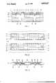
- FIG. 1is an enlarged fragmentary cross-sectional view illustrating schematically the arrangement of a typical ink jet system in accordance with the invention
- FIG. 2is an enlarged fragmentary plan view of the system shown in FIG. 1 schematically illustrating the polarization arrangement of the piezoelectric transducer
- FIG. 3is a schematic cross-sectional view illustrating a representative method for polarizing a piezoelectric plate to provide a transducer in accordance with the invention.
- an ink jet headin the typical embodiment of the invention illustrated in the schematic views of FIGS. 1 and 2, includes a pressure chamber plate 10 formed in the usual manner with pressure chambers 11 to which ink is supplied during operation of the system and a stiffener plate 12 providing the lower wall for the pressure chambers as viewed in FIG. 1.
- the stiffener platehas apertures 13 at one end of the pressure chambers 11 to supply ink to the chambers from corresponding ink ducts (not shown) and includes similar apertures 14 at the opposite end which communicate with ink jet orifices 15 provided in an orifice plate 16.
- the thickness of the pressure chamber plate 10may, for example, be about 3 mils and the pressure chambers 11 may be about 40 mils wide and 375 mils long, while the stiffener plate 12 may, for example, be about 5 to 10 mils thick with apertures 13 and 14 about 5 to 10 mils in diameter.
- the orifice plate 16may, for example, be about 2 mils thick with ink jet orifices 15 about 1 mil in diameter.
- a piezoelectric transducer member 17is mounted adjacent to the pressure chamber plate 10 on the side opposite the stiffener plate 12 and forms the upper wall of the pressure chambers 11 as viewed in FIG. 1.
- the transducer member 17includes a plate 18 of piezoelectric material and, in accordance with the invention, the piezoelectric plate 18 is polarized in the plane of the plate 18 so that the direction of polarization extends from the center of each pressure chamber toward the adjacent longest walls 19 of the pressure chamber as indicated by the arrows P in FIGS. 1 and 2.
- the piezoelectric transducer member 17includes a continuous conductive electrode 20 covering the surface of the piezoelectric plate 18 on the side toward the pressure chambers 11 and has electrode strips 21 mounted at selected positions on the side away from the pressure chambers.
- the electrode strips 21have a length approximately equal to the length of the pressure chamber, and two strips are positioned opposite each pressure chamber and are located between the center and the longest walls 19 of the pressure chamber.
- the entire transducer member 17may be coated with a thin layer of an insulating material (not shown).
- a voltage pulse of the appropriate polarityis applied between the corresponding electrodes 21 and the common electrode 20, producing an electric field through the adjacent portions of the transducer in a direction orthogonal to the direction of polarization.
- the voltage pulse on the electrodes 21is positive. This field causes a shear motion in the affected portions of the transducer plate which deflects the center of the affected region inwardly into the pressure chamber 11 in the manner illustrated in the righthand chamber in the view shown in FIG. 1.
- a relatively high piezoelectric coefficientof about 0.5 to 1.0 nanometers per volt, for example, is provided and, moreover, the electric field, being applied by electrodes disposed on opposite sides of the transducer, interacts more effectively with the transducer polarization than a field applied by electrodes disposed on one surface of a transducer which is polarized perpendicularly to its length. Consequently, the transducer motion required for effective drop ejection from the orifice 15 communicating with a chamber 11 can be produced by applying a relatively low voltage, in the range of about 10 to 30 volts for example, between the selected electrodes 21 and the common electrode 20, requiring only minimal insulation on the corresponding conductors.
- the electrodes 20 and 21are separated by the insulating piezoelectric plate 18, there is no danger of shorting o voltage leakage between them and they need only be protected by a relatively thin insulating layer against shorting or leakage to other conductive components in the system.
- the sheet of piezoelectric materialis disposed between polarizing electrodes providing the required polarizing fields in the manner shown in FIG. 3.
- negative polarizing electrodes 23are positioned on opposite sides of the plate 18 at locations corresponding to the centers of the pressure chambers 11 and positive polarizing electrodes 22 are positioned on opposite sides of the piezoelectric plate at locations corresponding to the portions of the pressure chamber plate 10 which provide the walls 19 of the pressure chambers.
- the resulting electric field applied by the electrodesproduces polarization field lines 24 extending between the electrodes in the plane of the piezoelectric plate.
- the common electrode 20is affixed to one side of the polarized plate and the strip electrodes 21 are affixed to the opposite side of the plate in the regions adjacent to the parallel field lines 24.
- the common electrode 20 of FIG. 1may consist of a plurality of strips corresponding to the electrode strips 21 and positioned across the plate 18 from those strips.
- the electrode strips 21, and the corresponding common electrode strips, if used,may be applied by masking techniques using a mask which is the negative of the pattern for the polarizing electrodes 22 and 23 shown in FIG. 3.
Landscapes
- Physics & Mathematics (AREA)
- General Physics & Mathematics (AREA)
- Particle Formation And Scattering Control In Inkjet Printers (AREA)
- Ink Jet (AREA)
Abstract
Description
Claims (18)
Priority Applications (9)
| Application Number | Priority Date | Filing Date | Title |
|---|---|---|---|
| US07/161,855US4825227A (en) | 1988-02-29 | 1988-02-29 | Shear mode transducer for ink jet systems |
| BR898905707ABR8905707A (en) | 1988-02-29 | 1989-02-15 | SHEAR MODULE TRANSDUCER FOR INK JET SYSTEMS |
| DE68916364TDE68916364T3 (en) | 1988-02-29 | 1989-02-15 | SHEAR FORCE TRANSMITTER FOR INK JET SYSTEMS. |
| PCT/US1989/000622WO1989008240A1 (en) | 1988-02-29 | 1989-02-15 | Shear mode transducer for ink jet systems |
| JP1502508AJPH0733089B2 (en) | 1988-02-29 | 1989-02-15 | Shear transducer for ink jet system |
| AT89902695TATE107768T1 (en) | 1988-02-29 | 1989-02-15 | SHEAR TRANSDUCERS FOR INKJET SYSTEMS. |
| EP89902695AEP0364518B2 (en) | 1988-02-29 | 1989-02-15 | Shear mode transducer for ink jet systems |
| KR1019890701998AKR930003500B1 (en) | 1988-02-29 | 1989-02-15 | Piezoelectric transducer device for ink jet system and manufacturing method thereof |
| CA000592138ACA1311964C (en) | 1988-02-29 | 1989-02-27 | Shear mode transducer for ink jet systems |
Applications Claiming Priority (1)
| Application Number | Priority Date | Filing Date | Title |
|---|---|---|---|
| US07/161,855US4825227A (en) | 1988-02-29 | 1988-02-29 | Shear mode transducer for ink jet systems |
Publications (1)
| Publication Number | Publication Date |
|---|---|
| US4825227Atrue US4825227A (en) | 1989-04-25 |
Family
ID=22583057
Family Applications (1)
| Application Number | Title | Priority Date | Filing Date |
|---|---|---|---|
| US07/161,855Expired - LifetimeUS4825227A (en) | 1988-02-29 | 1988-02-29 | Shear mode transducer for ink jet systems |
Country Status (9)
| Country | Link |
|---|---|
| US (1) | US4825227A (en) |
| EP (1) | EP0364518B2 (en) |
| JP (1) | JPH0733089B2 (en) |
| KR (1) | KR930003500B1 (en) |
| AT (1) | ATE107768T1 (en) |
| BR (1) | BR8905707A (en) |
| CA (1) | CA1311964C (en) |
| DE (1) | DE68916364T3 (en) |
| WO (1) | WO1989008240A1 (en) |
Cited By (110)
| Publication number | Priority date | Publication date | Assignee | Title |
|---|---|---|---|---|
| EP0416540A3 (en)* | 1989-09-05 | 1991-06-12 | Seiko Epson Corporation | Ink jet printer recording head |
| US5086308A (en)* | 1989-07-19 | 1992-02-04 | Brother Kogyo Kabushiki Kaisha | Piezoelectric ink jet print head including common laminar piezoelectric element for two or more ink jetting devices |
| WO1992009111A1 (en)* | 1990-11-20 | 1992-05-29 | Spectra, Inc. | Thin-film transducer ink jet head |
| WO1992008617A1 (en)* | 1990-11-20 | 1992-05-29 | Spectra, Inc. | Piezoelectric transducers for ink jet systems |
| US5210455A (en)* | 1990-07-26 | 1993-05-11 | Ngk Insulators, Ltd. | Piezoelectric/electrostrictive actuator having ceramic substrate having recess defining thin-walled portion |
| US5227813A (en)* | 1991-08-16 | 1993-07-13 | Compaq Computer Corporation | Sidewall actuator for a high density ink jet printhead |
| US5235352A (en)* | 1991-08-16 | 1993-08-10 | Compaq Computer Corporation | High density ink jet printhead |
| EP0541294A3 (en)* | 1991-11-06 | 1993-08-25 | Brother Kogyo Kabushiki Kaisha | Droplet ejecting device |
| US5266964A (en)* | 1990-09-14 | 1993-11-30 | Brother Kogyo Kabushiki Kaisha | Piezoelectric ink jet printer head |
| US5363131A (en)* | 1990-10-05 | 1994-11-08 | Seiko Epson Corporation | Ink jet recording head |
| US5369420A (en)* | 1990-10-05 | 1994-11-29 | Xaar Limited | Method of testing multi-channel array pulsed droplet deposition apparatus |
| US5371527A (en)* | 1991-04-25 | 1994-12-06 | Hewlett-Packard Company | Orificeless printhead for an ink jet printer |
| US5373314A (en)* | 1992-08-27 | 1994-12-13 | Compaq Computer Corporation | Ink jet print head |
| US5400064A (en)* | 1991-08-16 | 1995-03-21 | Compaq Computer Corporation | High density ink jet printhead with double-U channel actuator |
| US5402162A (en)* | 1991-08-16 | 1995-03-28 | Compaq Computer Corporation | Integrated multi-color ink jet printhead |
| US5402159A (en)* | 1990-03-26 | 1995-03-28 | Brother Kogyo Kabushiki Kaisha | Piezoelectric ink jet printer using laminated piezoelectric actuator |
| US5406319A (en)* | 1991-08-16 | 1995-04-11 | Compaq Computer Corporation | Enhanced U type ink jet printheads |
| US5426455A (en)* | 1993-05-10 | 1995-06-20 | Compaq Computer Corporation | Three element switched digital drive system for an ink jet printhead |
| US5430344A (en)* | 1991-07-18 | 1995-07-04 | Ngk Insulators, Ltd. | Piezoelectric/electrostrictive element having ceramic substrate formed essentially of stabilized zirconia |
| US5433809A (en)* | 1991-08-16 | 1995-07-18 | Compaq Computer Corporation | Method of manufacturing a high density ink jet printhead |
| US5436648A (en)* | 1991-08-16 | 1995-07-25 | Compaq Computer Corporation | Switched digital drive system for an ink jet printhead |
| US5438350A (en)* | 1990-10-18 | 1995-08-01 | Xaar Limited | Method of operating multi-channel array droplet deposition apparatus |
| US5444467A (en)* | 1993-05-10 | 1995-08-22 | Compaq Computer Corporation | Differential drive system for an ink jet printhead |
| US5461403A (en)* | 1991-08-16 | 1995-10-24 | Compaq Computer Corporation | Droplet volume modulation techniques for ink jet printheads |
| DE19515406A1 (en)* | 1994-04-26 | 1995-11-02 | Seiko Epson Corp | Ink jet printhead and manufacturing method for the ink jet printhead |
| US5466985A (en)* | 1993-06-30 | 1995-11-14 | Brother Kogyo Kabushiki Kaisha | Method for non-destructively driving a thickness shear mode piezoelectric actuator |
| US5475408A (en)* | 1991-01-07 | 1995-12-12 | Sharp Kabushiki Kaisha | Ink jet head apparatus |
| US5479684A (en)* | 1993-12-30 | 1996-01-02 | Compaq Computer Corporation | Method of manufacturing ink jet printheads by induction heating of low melting point metal alloys |
| EP0695639A2 (en) | 1994-06-14 | 1996-02-07 | Compaq Computer Corporation | Method of manufacturing a sidewall actuator array for an ink jet printhead |
| US5505364A (en)* | 1993-12-30 | 1996-04-09 | Compaq Computer Corporation | Method of manufacturing ink jet printheads |
| US5510819A (en)* | 1992-02-24 | 1996-04-23 | Rohm Co., Ltd. | Ink jet printing head and electronic machine incorporating the same |
| US5521618A (en)* | 1991-08-16 | 1996-05-28 | Compaq Computer Corporation | Dual element switched digital drive system for an ink jet printhead |
| US5557304A (en)* | 1993-05-10 | 1996-09-17 | Compaq Computer Corporation | Spot size modulatable ink jet printhead |
| DE19639436A1 (en)* | 1995-09-25 | 1997-04-17 | Sharp Kk | Ink jet print head with bimorph piezo electric actuators |
| US5625393A (en)* | 1993-11-11 | 1997-04-29 | Brother Ind Ltd | Ink ejecting apparatus with ejecting chambers and non ejecting chambers |
| US5627632A (en)* | 1996-03-11 | 1997-05-06 | Eastman Kodak Company | Electrostatographic apparatus having a toner transfer assistance system and process |
| US5666144A (en)* | 1993-05-26 | 1997-09-09 | Brother Kogyo Kabushiki Kaisha | Ink droplet jet device having segmented piezoelectric ink chambers with different polarization |
| US5666141A (en)* | 1993-07-13 | 1997-09-09 | Sharp Kabushiki Kaisha | Ink jet head and a method of manufacturing thereof |
| EP0803918A1 (en)* | 1996-04-11 | 1997-10-29 | Seiko Epson Corporation | Piezoelectric vibrator unit, ink jet recording head using the piezoelectric vibrator unit and method of manufacturing the same |
| US5691752A (en)* | 1990-11-20 | 1997-11-25 | Spectra, Inc. | Perovskite thin-film ink jet transducer |
| US5691593A (en)* | 1989-07-11 | 1997-11-25 | Ngk Insulators, Ltd. | Piezoelectric/electrostrictive actuator having at least one piezoelectric/electrostrictive film |
| EP0810676A1 (en)* | 1996-05-27 | 1997-12-03 | Ngk Insulators, Ltd. | Piezoelectric film-type element |
| US5708914A (en)* | 1995-09-20 | 1998-01-13 | Eastman Kodak Company | Electrostatographic apparatus having fusing process and system for improved toner offset control |
| US5764255A (en)* | 1994-02-08 | 1998-06-09 | Sharp Kabushiki Kaisha | Ink jet head with a deformable piezoelectric vibrating plate |
| US5786655A (en)* | 1994-05-26 | 1998-07-28 | Canon Kabushiki Kaisha | Strain element and vibration device |
| US5828393A (en)* | 1991-10-17 | 1998-10-27 | Minolta Co., Ltd. | Ink jet head for jettting ink onto an ink carrier and an ink jet recording apparatus for forming an ink image onto an ink carrier |
| WO1999001284A1 (en)* | 1997-07-02 | 1999-01-14 | Xaar Technology Limited | Drop on demand ink jet printing apparatus |
| US5889352A (en)* | 1995-10-13 | 1999-03-30 | Ngk Insulators, Ltd. | Piezo-electric/electrostrictive film type element |
| US5901425A (en) | 1996-08-27 | 1999-05-11 | Topaz Technologies Inc. | Inkjet print head apparatus |
| US5988800A (en)* | 1991-12-27 | 1999-11-23 | Rohm Co., Ltd. | Ink jet printing head and apparatus incorporating the same |
| US6029896A (en)* | 1997-09-30 | 2000-02-29 | Microfab Technologies, Inc. | Method of drop size modulation with extended transition time waveform |
| US6174051B1 (en) | 1996-08-19 | 2001-01-16 | Brother Kogyo Kabushiki Kaisha | Ink jet head |
| US6188416B1 (en) | 1997-02-13 | 2001-02-13 | Microfab Technologies, Inc. | Orifice array for high density ink jet printhead |
| US6327120B1 (en)* | 1997-04-17 | 2001-12-04 | Fujitsu Limited | Actuator using piezoelectric element and head-positioning mechanism using the actuator |
| US6364460B1 (en) | 2000-06-13 | 2002-04-02 | Chad R. Sager | Liquid delivery system |
| US6371602B1 (en)* | 1996-10-07 | 2002-04-16 | Brother Kogyo Kabushiki Kaisha | Ink-jet recording head, and process for forming ink-jet recording head |
| EP1213145A2 (en) | 1996-03-15 | 2002-06-12 | Xaar Technology Limited | Operation of droplet deposition apparatus |
| US6505920B1 (en)* | 1999-06-17 | 2003-01-14 | Scitex Digital Printing, Inc. | Synchronously stimulated continuous ink jet head |
| US6565196B2 (en)* | 2000-07-11 | 2003-05-20 | Matsushita Electric Industrial Co., Ltd. | Ink jet head, method of manufacturing the same and ink jet recording apparatus |
| US20030107622A1 (en)* | 2001-12-06 | 2003-06-12 | Hiroto Sugahara | Piezoelectric actuator |
| US6584708B2 (en)* | 1999-07-13 | 2003-07-01 | Samsung Electro-Mechanics Co., Ltd. | Membraneless piezoelectric/electrostrictive microactuator and manufacturing method thereof |
| US6623110B2 (en)* | 1998-10-20 | 2003-09-23 | Fujitsu, Limited | Ink jet recording head and production methods therefor and printer apparatus therewith |
| US6679588B2 (en)* | 2001-03-29 | 2004-01-20 | Brother Kogyo Kabushiki Kaisha | Piezoelectric transducer and ink ejector using piezoelectric transducer |
| US20040091608A1 (en)* | 1999-10-01 | 2004-05-13 | Ngk Insulators, Ltd. | Piezoelectric/electrostrictive device and method of manufacturing same |
| US6739704B2 (en)* | 2001-03-29 | 2004-05-25 | Brother Kogyo Kabushiki Kaisha | Piezoelectric transducer and ink ejector using piezoelectric transducer |
| US20040183408A1 (en)* | 2003-03-21 | 2004-09-23 | Board Of Control Of Michigan Technological University | Actuator |
| US20040207695A1 (en)* | 2003-02-07 | 2004-10-21 | Canon Kabushiki Kaisha | Dielectric film structure, piezoelectric actuator using dielectric element film structure and ink jet head |
| US20040252149A1 (en)* | 2003-06-11 | 2004-12-16 | Jaan Laaspere | Ink-jet printing |
| WO2004113083A1 (en) | 2003-06-13 | 2004-12-29 | Dimatix, Inc. | Apparatus for depositing droplets |
| US20050018021A1 (en)* | 2000-03-31 | 2005-01-27 | Fuji Photo Film Co., Ltd. | Multi-nozzle ink jet head |
| US20050093913A1 (en)* | 2003-06-11 | 2005-05-05 | Spectra, Inc. | Tilt head cleaner |
| US20050157148A1 (en)* | 2004-01-20 | 2005-07-21 | Richard Baker | Printing on edible substrates |
| US20050270329A1 (en)* | 2004-04-30 | 2005-12-08 | Hoisington Paul A | Droplet ejection apparatus alignment |
| US20060034984A1 (en)* | 2004-06-10 | 2006-02-16 | Sensient Imaging Technologies Inc. | Food grade ink jet inks for printing on edible substrates |
| US20060061791A1 (en)* | 2004-09-07 | 2006-03-23 | Laaspere Jaan T | Variable resolution in printing system and method |
| US20060152556A1 (en)* | 2001-12-06 | 2006-07-13 | Hiroto Sugahara | Liquid transporting apparatus and method for producing liquid transporting apparatus |
| US20060192808A1 (en)* | 2004-02-19 | 2006-08-31 | Dimatix, Inc., A Delaware Corporation | Printhead |
| US20060209135A1 (en)* | 2005-03-21 | 2006-09-21 | Hoisington Paul A | Drop ejection device |
| US20070040869A1 (en)* | 2005-08-19 | 2007-02-22 | Barton William M Jr | Print head for large scale printing apparatus |
| US20080032011A1 (en)* | 2005-07-01 | 2008-02-07 | Sensient Colors Inc. | Flavored and Edible Colored Fluids for Printing on Edible Substrates and Precision Deposition Thereof |
| US20080075859A1 (en)* | 2004-01-20 | 2008-03-27 | Baker Richard J | Printing, Depositing, or Coating On Flowable Substrates |
| US20080094433A1 (en)* | 2003-06-13 | 2008-04-24 | Dimatix, Inc., A Delaware Corporation | Apparatus for Depositing Droplets |
| US20080122911A1 (en)* | 2006-11-28 | 2008-05-29 | Page Scott G | Drop ejection apparatuses |
| US7413284B2 (en) | 2004-04-30 | 2008-08-19 | Fujifilm Dimatix, Inc. | Mounting assembly |
| US20080239020A1 (en)* | 2007-03-30 | 2008-10-02 | Brother Kogyo Kabushiki Kaisha | Piezoelectric actuator and liquid transport apparatus provided with piezoelectric actuator |
| US7431956B2 (en) | 2003-06-20 | 2008-10-07 | Sensient Imaging Technologies, Inc. | Food grade colored fluids for printing on edible substrates |
| US20080316264A1 (en)* | 1997-07-15 | 2008-12-25 | Silverbrook Research Pty Ltd | Printhead integrated circuit with nozzles in thin surface layer |
| US20090186121A1 (en)* | 2006-05-01 | 2009-07-23 | Sensient Colors Inc. | Modified edible substrates suitable for printing |
| US20090269447A1 (en)* | 2008-04-25 | 2009-10-29 | Karen Brimmer | Heat-triggered colorants and methods of making and using the same |
| US20090298952A1 (en)* | 2008-05-07 | 2009-12-03 | Brimmer Karen S | Platable soluble dyes |
| US20100047415A1 (en)* | 2005-07-01 | 2010-02-25 | Sensient Imaging Technologies Inc. | Ink-jettable flavored fluids for printing on edible substrates |
| US20100055264A1 (en)* | 2008-08-29 | 2010-03-04 | Sensient Colors Inc. | Flavored and edible colored waxes and methods for precision deposition on edible substrates |
| US20110001780A1 (en)* | 2009-07-02 | 2011-01-06 | Fujifilm Dimatix, Inc. | Positioning jetting assemblies |
| US20110012954A1 (en)* | 2009-07-20 | 2011-01-20 | Markem-Imaje Corporation | Solvent-based inkjet ink formulations |
| DE10210257B4 (en)* | 2002-01-14 | 2011-02-17 | Physik Instrumente (Pi) Gmbh & Co. Kg | Piezoelectric actuator |
| US20110109696A1 (en)* | 2008-05-23 | 2011-05-12 | Fujifilm Corporation | Adjustable printhead mounting |
| US20110128324A1 (en)* | 2008-05-23 | 2011-06-02 | Kevin Von Essen | Method and apparatus for mounting a fluid ejection module |
| CN101342520B (en)* | 2007-07-10 | 2011-08-03 | 研能科技股份有限公司 | micro droplet ejection structure |
| USD652446S1 (en) | 2009-07-02 | 2012-01-17 | Fujifilm Dimatix, Inc. | Printhead assembly |
| WO2012009498A2 (en) | 2010-07-15 | 2012-01-19 | Fujifilm Dimatix, Inc. | Printing objects using a rolling buffer |
| USD653284S1 (en) | 2009-07-02 | 2012-01-31 | Fujifilm Dimatix, Inc. | Printhead frame |
| EP2415606A2 (en) | 2003-12-30 | 2012-02-08 | Dimatix, Inc. | Drop ejection assembly |
| US20120062658A1 (en)* | 2010-09-14 | 2012-03-15 | Osamu Koseki | Liquid jet head, liquid jet apparatus, and method of manufacturing liquid jet head |
| US8142005B2 (en) | 2005-05-09 | 2012-03-27 | Fujifilm Dimatix, Inc. | Ink jet printing system |
| WO2013039865A2 (en) | 2011-09-13 | 2013-03-21 | Fujifilm Dimatix, Inc. | Fluid jetting with delays |
| CN103963465A (en)* | 2013-02-06 | 2014-08-06 | 精工电子打印科技有限公司 | Liquid jet head, method of manufacturing liquid jet head, and liquid jet apparatus |
| US20140293155A1 (en)* | 2013-04-02 | 2014-10-02 | Samsung Display Co., Ltd. | Energy recovery system for recovering pressure energy of touch input to touch screen panel |
| WO2014123615A3 (en)* | 2012-12-05 | 2014-11-13 | Rensselaer Polytechnic Institute | Piezoelectric driven oscillating surface |
| WO2023200954A1 (en) | 2022-04-13 | 2023-10-19 | Aprecia Pharmaceuticals LLC | System and method for additive manufacturing using an omnidirectional magnetic movement apparatus |
| EP4465768A1 (en)* | 2023-05-17 | 2024-11-20 | ASML Netherlands B.V. | Droplet generator |
Families Citing this family (3)
| Publication number | Priority date | Publication date | Assignee | Title |
|---|---|---|---|---|
| JP3521499B2 (en)* | 1993-11-26 | 2004-04-19 | 日本碍子株式会社 | Piezoelectric / electrostrictive film type element |
| GB0105618D0 (en)* | 2001-03-07 | 2001-04-25 | 1 Ipr Ltd | Piezoelectric devices |
| DE602004031427D1 (en)* | 2003-07-22 | 2011-03-31 | Ngk Insulators Ltd | MEMBER ELEMENT AND DEVICE WITH CONTROLLER ELEMENT |
Citations (5)
| Publication number | Priority date | Publication date | Assignee | Title |
|---|---|---|---|---|
| US2540412A (en)* | 1947-12-26 | 1951-02-06 | Zenith Radio Corp | Piezoelectric transducer and method for producing same |
| US3175107A (en)* | 1957-02-16 | 1965-03-23 | Philips Corp | Piezoelectric transducer with longitudinal polarization |
| US4019073A (en)* | 1975-08-12 | 1977-04-19 | Vladimir Sergeevich Vishnevsky | Piezoelectric motor structures |
| US4491761A (en)* | 1981-12-28 | 1985-01-01 | United Technologies Corporation | Planar piezoelectric deflector with arrays of alternate piezoelectric effect |
| US4584590A (en)* | 1982-05-28 | 1986-04-22 | Xerox Corporation | Shear mode transducer for drop-on-demand liquid ejector |
Family Cites Families (1)
| Publication number | Priority date | Publication date | Assignee | Title |
|---|---|---|---|---|
| US4879568A (en)* | 1987-01-10 | 1989-11-07 | Am International, Inc. | Droplet deposition apparatus |
- 1988
- 1988-02-29USUS07/161,855patent/US4825227A/ennot_activeExpired - Lifetime
- 1989
- 1989-02-15EPEP89902695Apatent/EP0364518B2/ennot_activeExpired - Lifetime
- 1989-02-15DEDE68916364Tpatent/DE68916364T3/ennot_activeExpired - Lifetime
- 1989-02-15BRBR898905707Apatent/BR8905707A/ennot_activeIP Right Cessation
- 1989-02-15ATAT89902695Tpatent/ATE107768T1/ennot_activeIP Right Cessation
- 1989-02-15KRKR1019890701998Apatent/KR930003500B1/ennot_activeExpired - Lifetime
- 1989-02-15WOPCT/US1989/000622patent/WO1989008240A1/enactiveIP Right Grant
- 1989-02-15JPJP1502508Apatent/JPH0733089B2/ennot_activeExpired - Lifetime
- 1989-02-27CACA000592138Apatent/CA1311964C/ennot_activeExpired - Lifetime
Patent Citations (5)
| Publication number | Priority date | Publication date | Assignee | Title |
|---|---|---|---|---|
| US2540412A (en)* | 1947-12-26 | 1951-02-06 | Zenith Radio Corp | Piezoelectric transducer and method for producing same |
| US3175107A (en)* | 1957-02-16 | 1965-03-23 | Philips Corp | Piezoelectric transducer with longitudinal polarization |
| US4019073A (en)* | 1975-08-12 | 1977-04-19 | Vladimir Sergeevich Vishnevsky | Piezoelectric motor structures |
| US4491761A (en)* | 1981-12-28 | 1985-01-01 | United Technologies Corporation | Planar piezoelectric deflector with arrays of alternate piezoelectric effect |
| US4584590A (en)* | 1982-05-28 | 1986-04-22 | Xerox Corporation | Shear mode transducer for drop-on-demand liquid ejector |
Cited By (186)
| Publication number | Priority date | Publication date | Assignee | Title |
|---|---|---|---|---|
| US5691593A (en)* | 1989-07-11 | 1997-11-25 | Ngk Insulators, Ltd. | Piezoelectric/electrostrictive actuator having at least one piezoelectric/electrostrictive film |
| US6441537B1 (en)* | 1989-07-11 | 2002-08-27 | Ngk Insulators, Ltd. | Piezoelectric/electrostrictive actuator having at least one piezoelectric/electrostrictive film |
| US5086308A (en)* | 1989-07-19 | 1992-02-04 | Brother Kogyo Kabushiki Kaisha | Piezoelectric ink jet print head including common laminar piezoelectric element for two or more ink jetting devices |
| US5255016A (en)* | 1989-09-05 | 1993-10-19 | Seiko Epson Corporation | Ink jet printer recording head |
| EP0416540A3 (en)* | 1989-09-05 | 1991-06-12 | Seiko Epson Corporation | Ink jet printer recording head |
| US5402159A (en)* | 1990-03-26 | 1995-03-28 | Brother Kogyo Kabushiki Kaisha | Piezoelectric ink jet printer using laminated piezoelectric actuator |
| US5210455A (en)* | 1990-07-26 | 1993-05-11 | Ngk Insulators, Ltd. | Piezoelectric/electrostrictive actuator having ceramic substrate having recess defining thin-walled portion |
| US5681410A (en)* | 1990-07-26 | 1997-10-28 | Ngk Insulators, Ltd. | Method of producing a piezoelectric/electrostrictive actuator |
| US5266964A (en)* | 1990-09-14 | 1993-11-30 | Brother Kogyo Kabushiki Kaisha | Piezoelectric ink jet printer head |
| US5363131A (en)* | 1990-10-05 | 1994-11-08 | Seiko Epson Corporation | Ink jet recording head |
| US5369420A (en)* | 1990-10-05 | 1994-11-29 | Xaar Limited | Method of testing multi-channel array pulsed droplet deposition apparatus |
| US5438350A (en)* | 1990-10-18 | 1995-08-01 | Xaar Limited | Method of operating multi-channel array droplet deposition apparatus |
| WO1992008617A1 (en)* | 1990-11-20 | 1992-05-29 | Spectra, Inc. | Piezoelectric transducers for ink jet systems |
| US5265315A (en)* | 1990-11-20 | 1993-11-30 | Spectra, Inc. | Method of making a thin-film transducer ink jet head |
| US5202703A (en)* | 1990-11-20 | 1993-04-13 | Spectra, Inc. | Piezoelectric transducers for ink jet systems |
| US5446484A (en)* | 1990-11-20 | 1995-08-29 | Spectra, Inc. | Thin-film transducer ink jet head |
| US5691752A (en)* | 1990-11-20 | 1997-11-25 | Spectra, Inc. | Perovskite thin-film ink jet transducer |
| WO1992009111A1 (en)* | 1990-11-20 | 1992-05-29 | Spectra, Inc. | Thin-film transducer ink jet head |
| US5475408A (en)* | 1991-01-07 | 1995-12-12 | Sharp Kabushiki Kaisha | Ink jet head apparatus |
| US5371527A (en)* | 1991-04-25 | 1994-12-06 | Hewlett-Packard Company | Orificeless printhead for an ink jet printer |
| US5691594A (en)* | 1991-07-18 | 1997-11-25 | Ngk Insulators, Ltd. | Piezoelectric/electrostricitve element having ceramic substrate formed essentially of stabilized zirconia |
| US5430344A (en)* | 1991-07-18 | 1995-07-04 | Ngk Insulators, Ltd. | Piezoelectric/electrostrictive element having ceramic substrate formed essentially of stabilized zirconia |
| US5400064A (en)* | 1991-08-16 | 1995-03-21 | Compaq Computer Corporation | High density ink jet printhead with double-U channel actuator |
| US5433809A (en)* | 1991-08-16 | 1995-07-18 | Compaq Computer Corporation | Method of manufacturing a high density ink jet printhead |
| US5436648A (en)* | 1991-08-16 | 1995-07-25 | Compaq Computer Corporation | Switched digital drive system for an ink jet printhead |
| US5406319A (en)* | 1991-08-16 | 1995-04-11 | Compaq Computer Corporation | Enhanced U type ink jet printheads |
| US5554247A (en)* | 1991-08-16 | 1996-09-10 | Compaq Computer Corporation | Method of manufacturing a high density ink jet printhead array |
| US5402162A (en)* | 1991-08-16 | 1995-03-28 | Compaq Computer Corporation | Integrated multi-color ink jet printhead |
| US5461403A (en)* | 1991-08-16 | 1995-10-24 | Compaq Computer Corporation | Droplet volume modulation techniques for ink jet printheads |
| US5543009A (en)* | 1991-08-16 | 1996-08-06 | Compaq Computer Corporation | Method of manufacturing a sidewall actuator array for an ink jet printhead |
| US5235352A (en)* | 1991-08-16 | 1993-08-10 | Compaq Computer Corporation | High density ink jet printhead |
| US5227813A (en)* | 1991-08-16 | 1993-07-13 | Compaq Computer Corporation | Sidewall actuator for a high density ink jet printhead |
| US5521618A (en)* | 1991-08-16 | 1996-05-28 | Compaq Computer Corporation | Dual element switched digital drive system for an ink jet printhead |
| US5828393A (en)* | 1991-10-17 | 1998-10-27 | Minolta Co., Ltd. | Ink jet head for jettting ink onto an ink carrier and an ink jet recording apparatus for forming an ink image onto an ink carrier |
| US5434608A (en)* | 1991-11-06 | 1995-07-18 | Brother Kogyo Kabushiki Kaisha | Droplet ejecting device |
| EP0541294A3 (en)* | 1991-11-06 | 1993-08-25 | Brother Kogyo Kabushiki Kaisha | Droplet ejecting device |
| US5988800A (en)* | 1991-12-27 | 1999-11-23 | Rohm Co., Ltd. | Ink jet printing head and apparatus incorporating the same |
| US5510819A (en)* | 1992-02-24 | 1996-04-23 | Rohm Co., Ltd. | Ink jet printing head and electronic machine incorporating the same |
| US5373314A (en)* | 1992-08-27 | 1994-12-13 | Compaq Computer Corporation | Ink jet print head |
| US5444467A (en)* | 1993-05-10 | 1995-08-22 | Compaq Computer Corporation | Differential drive system for an ink jet printhead |
| US5557304A (en)* | 1993-05-10 | 1996-09-17 | Compaq Computer Corporation | Spot size modulatable ink jet printhead |
| US5426455A (en)* | 1993-05-10 | 1995-06-20 | Compaq Computer Corporation | Three element switched digital drive system for an ink jet printhead |
| US5666144A (en)* | 1993-05-26 | 1997-09-09 | Brother Kogyo Kabushiki Kaisha | Ink droplet jet device having segmented piezoelectric ink chambers with different polarization |
| US5466985A (en)* | 1993-06-30 | 1995-11-14 | Brother Kogyo Kabushiki Kaisha | Method for non-destructively driving a thickness shear mode piezoelectric actuator |
| US5666141A (en)* | 1993-07-13 | 1997-09-09 | Sharp Kabushiki Kaisha | Ink jet head and a method of manufacturing thereof |
| US5625393A (en)* | 1993-11-11 | 1997-04-29 | Brother Ind Ltd | Ink ejecting apparatus with ejecting chambers and non ejecting chambers |
| US5505364A (en)* | 1993-12-30 | 1996-04-09 | Compaq Computer Corporation | Method of manufacturing ink jet printheads |
| US5479684A (en)* | 1993-12-30 | 1996-01-02 | Compaq Computer Corporation | Method of manufacturing ink jet printheads by induction heating of low melting point metal alloys |
| US5764255A (en)* | 1994-02-08 | 1998-06-09 | Sharp Kabushiki Kaisha | Ink jet head with a deformable piezoelectric vibrating plate |
| DE19515406A1 (en)* | 1994-04-26 | 1995-11-02 | Seiko Epson Corp | Ink jet printhead and manufacturing method for the ink jet printhead |
| US6073321A (en)* | 1994-04-26 | 2000-06-13 | Seiko Epson Corporation | Manufacturing method for an ink jet recording head |
| US5929881A (en)* | 1994-04-26 | 1999-07-27 | Seiko Epson Corporation | Ink jet recording head having improved arrangement of electrodes |
| DE19515406C2 (en)* | 1994-04-26 | 1999-04-01 | Seiko Epson Corp | Ink jet printhead and manufacturing method for the ink jet printhead |
| US5786655A (en)* | 1994-05-26 | 1998-07-28 | Canon Kabushiki Kaisha | Strain element and vibration device |
| EP0695639A2 (en) | 1994-06-14 | 1996-02-07 | Compaq Computer Corporation | Method of manufacturing a sidewall actuator array for an ink jet printhead |
| US5708914A (en)* | 1995-09-20 | 1998-01-13 | Eastman Kodak Company | Electrostatographic apparatus having fusing process and system for improved toner offset control |
| US5988799A (en)* | 1995-09-25 | 1999-11-23 | Sharp Kabushiki Kaisha | Ink-jet head having ink chamber and non-ink chamber divided by structural element subjected to freckling deformation |
| DE19639436C2 (en)* | 1995-09-25 | 1998-12-24 | Sharp Kk | Manufacturing process for an ink jet head |
| DE19639436A1 (en)* | 1995-09-25 | 1997-04-17 | Sharp Kk | Ink jet print head with bimorph piezo electric actuators |
| US5889352A (en)* | 1995-10-13 | 1999-03-30 | Ngk Insulators, Ltd. | Piezo-electric/electrostrictive film type element |
| US5627632A (en)* | 1996-03-11 | 1997-05-06 | Eastman Kodak Company | Electrostatographic apparatus having a toner transfer assistance system and process |
| EP1213145A2 (en) | 1996-03-15 | 2002-06-12 | Xaar Technology Limited | Operation of droplet deposition apparatus |
| EP0803918A1 (en)* | 1996-04-11 | 1997-10-29 | Seiko Epson Corporation | Piezoelectric vibrator unit, ink jet recording head using the piezoelectric vibrator unit and method of manufacturing the same |
| US6217158B1 (en) | 1996-04-11 | 2001-04-17 | Seiko Epson Corporation | Layered type ink jet recording head with improved piezoelectric actuator unit |
| EP0810676A1 (en)* | 1996-05-27 | 1997-12-03 | Ngk Insulators, Ltd. | Piezoelectric film-type element |
| US5852337A (en)* | 1996-05-27 | 1998-12-22 | Ngk Insulators, Ltd. | Piezoelectric film-type element |
| US6174051B1 (en) | 1996-08-19 | 2001-01-16 | Brother Kogyo Kabushiki Kaisha | Ink jet head |
| US5901425A (en) | 1996-08-27 | 1999-05-11 | Topaz Technologies Inc. | Inkjet print head apparatus |
| US6371602B1 (en)* | 1996-10-07 | 2002-04-16 | Brother Kogyo Kabushiki Kaisha | Ink-jet recording head, and process for forming ink-jet recording head |
| US6188416B1 (en) | 1997-02-13 | 2001-02-13 | Microfab Technologies, Inc. | Orifice array for high density ink jet printhead |
| US6327120B1 (en)* | 1997-04-17 | 2001-12-04 | Fujitsu Limited | Actuator using piezoelectric element and head-positioning mechanism using the actuator |
| US6538854B2 (en) | 1997-04-17 | 2003-03-25 | Fujitsu Limited | Actuator using piezoelectric element and head-positioning mechanism using the actuator |
| US6422690B1 (en) | 1997-07-02 | 2002-07-23 | Xaar Technology Limited | Drop on demand ink jet printing apparatus, method of ink jet printing, and method of manufacturing an ink jet printing apparatus |
| WO1999001284A1 (en)* | 1997-07-02 | 1999-01-14 | Xaar Technology Limited | Drop on demand ink jet printing apparatus |
| US20080316264A1 (en)* | 1997-07-15 | 2008-12-25 | Silverbrook Research Pty Ltd | Printhead integrated circuit with nozzles in thin surface layer |
| US6029896A (en)* | 1997-09-30 | 2000-02-29 | Microfab Technologies, Inc. | Method of drop size modulation with extended transition time waveform |
| US6623110B2 (en)* | 1998-10-20 | 2003-09-23 | Fujitsu, Limited | Ink jet recording head and production methods therefor and printer apparatus therewith |
| US6505920B1 (en)* | 1999-06-17 | 2003-01-14 | Scitex Digital Printing, Inc. | Synchronously stimulated continuous ink jet head |
| US6584708B2 (en)* | 1999-07-13 | 2003-07-01 | Samsung Electro-Mechanics Co., Ltd. | Membraneless piezoelectric/electrostrictive microactuator and manufacturing method thereof |
| US6883215B2 (en)* | 1999-10-01 | 2005-04-26 | Ngk Insulators, Ltd. | Piezoelectric/electrostrictive device and method of manufacturing same |
| US20040091608A1 (en)* | 1999-10-01 | 2004-05-13 | Ngk Insulators, Ltd. | Piezoelectric/electrostrictive device and method of manufacturing same |
| US20050018021A1 (en)* | 2000-03-31 | 2005-01-27 | Fuji Photo Film Co., Ltd. | Multi-nozzle ink jet head |
| US7159971B2 (en) | 2000-03-31 | 2007-01-09 | Fuji Photo Film Co., Ltd. | Multi-nozzle ink jet head |
| US6988792B2 (en)* | 2000-03-31 | 2006-01-24 | Fuji Photo Film Co., Ltd. | Multi-nozzle ink jet head |
| US20060066693A1 (en)* | 2000-03-31 | 2006-03-30 | Fuji Photo Film Co., Ltd. | Multi-nozzle ink jet head |
| US6364460B1 (en) | 2000-06-13 | 2002-04-02 | Chad R. Sager | Liquid delivery system |
| US6565196B2 (en)* | 2000-07-11 | 2003-05-20 | Matsushita Electric Industrial Co., Ltd. | Ink jet head, method of manufacturing the same and ink jet recording apparatus |
| US20030112301A1 (en)* | 2000-07-11 | 2003-06-19 | Matsushita Electric Industrial Co. Ltd. | Ink jet head, method of manufacturing the same and ink jet recording apparatus |
| US6811248B2 (en) | 2000-07-11 | 2004-11-02 | Matsushita Electric Industrial Co., Ltd. | Ink jet head, method of manufacturing the same and ink jet recording apparatus |
| US6739704B2 (en)* | 2001-03-29 | 2004-05-25 | Brother Kogyo Kabushiki Kaisha | Piezoelectric transducer and ink ejector using piezoelectric transducer |
| US6679588B2 (en)* | 2001-03-29 | 2004-01-20 | Brother Kogyo Kabushiki Kaisha | Piezoelectric transducer and ink ejector using piezoelectric transducer |
| US7434918B2 (en) | 2001-12-06 | 2008-10-14 | Brother Kogyo Kabushiki Kaisha | Liquid transporting apparatus and method for producing liquid transporting apparatus |
| US20030107622A1 (en)* | 2001-12-06 | 2003-06-12 | Hiroto Sugahara | Piezoelectric actuator |
| US20060038859A1 (en)* | 2001-12-06 | 2006-02-23 | Hiroto Sugahara | Piezoelectric actuator |
| US20060152556A1 (en)* | 2001-12-06 | 2006-07-13 | Hiroto Sugahara | Liquid transporting apparatus and method for producing liquid transporting apparatus |
| US6971738B2 (en)* | 2001-12-06 | 2005-12-06 | Brother Kogyo Kabushiki Kaisha | Piezoelectric actuator |
| DE10210257B4 (en)* | 2002-01-14 | 2011-02-17 | Physik Instrumente (Pi) Gmbh & Co. Kg | Piezoelectric actuator |
| US7938515B2 (en) | 2003-02-07 | 2011-05-10 | Canon Kabushiki Kaisha | Dielectric film structure, piezoelectric actuator using dielectric element film structure and ink jet head |
| US7059711B2 (en) | 2003-02-07 | 2006-06-13 | Canon Kabushiki Kaisha | Dielectric film structure, piezoelectric actuator using dielectric element film structure and ink jet head |
| US20040207695A1 (en)* | 2003-02-07 | 2004-10-21 | Canon Kabushiki Kaisha | Dielectric film structure, piezoelectric actuator using dielectric element film structure and ink jet head |
| US7513608B2 (en) | 2003-02-07 | 2009-04-07 | Canon Kabushiki Kaisha | Dielectric film structure, piezoelectric actuator using dielectric element film structure and ink jet head |
| US20090153626A1 (en)* | 2003-02-07 | 2009-06-18 | Canon Kabushiki Kaisha | Dielectric film structure, piezoelectric actuator using dielectric element film structure and ink jet head |
| US20060176342A1 (en)* | 2003-02-07 | 2006-08-10 | Canon Kabushiki Kaisha | Dielectric film structure, piezoelectric actuator using dielectric element film structure and ink jet head |
| US20040183408A1 (en)* | 2003-03-21 | 2004-09-23 | Board Of Control Of Michigan Technological University | Actuator |
| WO2004110772A2 (en) | 2003-06-11 | 2004-12-23 | Dimatix, Inc. | Ink-jet printing |
| US7063416B2 (en) | 2003-06-11 | 2006-06-20 | Dimatix, Inc | Ink-jet printing |
| US20050093913A1 (en)* | 2003-06-11 | 2005-05-05 | Spectra, Inc. | Tilt head cleaner |
| US20040252149A1 (en)* | 2003-06-11 | 2004-12-16 | Jaan Laaspere | Ink-jet printing |
| US7213901B2 (en) | 2003-06-11 | 2007-05-08 | Heidelberger Druckmaschinen Ag | Tilt head cleaner |
| US20080094433A1 (en)* | 2003-06-13 | 2008-04-24 | Dimatix, Inc., A Delaware Corporation | Apparatus for Depositing Droplets |
| WO2004113083A1 (en) | 2003-06-13 | 2004-12-29 | Dimatix, Inc. | Apparatus for depositing droplets |
| US20090004345A1 (en)* | 2003-06-20 | 2009-01-01 | Sensient Imaging Technologies, Inc. | Food grade colored fluids for printing on edible substrates |
| US7842319B2 (en) | 2003-06-20 | 2010-11-30 | Sensient Imaging Technologies, Inc. | Food grade colored fluids for printing on edible substrates |
| US7431956B2 (en) | 2003-06-20 | 2008-10-07 | Sensient Imaging Technologies, Inc. | Food grade colored fluids for printing on edible substrates |
| EP2415606A2 (en) | 2003-12-30 | 2012-02-08 | Dimatix, Inc. | Drop ejection assembly |
| WO2005069925A2 (en) | 2004-01-20 | 2005-08-04 | Dimatix, Inc. | Printing on edible substrates |
| US20080075859A1 (en)* | 2004-01-20 | 2008-03-27 | Baker Richard J | Printing, Depositing, or Coating On Flowable Substrates |
| US20050157148A1 (en)* | 2004-01-20 | 2005-07-21 | Richard Baker | Printing on edible substrates |
| US8753702B2 (en) | 2004-01-20 | 2014-06-17 | Fujifilm Dimatix, Inc. | Printing on edible substrates |
| US20070071851A1 (en)* | 2004-01-20 | 2007-03-29 | Fujifilm Dimatix, Inc. | Printing on Edible Substrates |
| US8635774B2 (en)* | 2004-02-19 | 2014-01-28 | Fujifilm Dimatix, Inc. | Methods of making a printhead |
| US20060192808A1 (en)* | 2004-02-19 | 2006-08-31 | Dimatix, Inc., A Delaware Corporation | Printhead |
| US8231202B2 (en) | 2004-04-30 | 2012-07-31 | Fujifilm Dimatix, Inc. | Droplet ejection apparatus alignment |
| US20050280678A1 (en)* | 2004-04-30 | 2005-12-22 | Andreas Bibl | Droplet ejection apparatus alignment |
| US20080211872A1 (en)* | 2004-04-30 | 2008-09-04 | Fujifilm Dimatix, Inc. | Droplet ejection apparatus alignment |
| US7673969B2 (en) | 2004-04-30 | 2010-03-09 | Fujifilm Dimatix, Inc. | Droplet ejection apparatus alignment |
| US7413284B2 (en) | 2004-04-30 | 2008-08-19 | Fujifilm Dimatix, Inc. | Mounting assembly |
| US20050270329A1 (en)* | 2004-04-30 | 2005-12-08 | Hoisington Paul A | Droplet ejection apparatus alignment |
| US7665815B2 (en) | 2004-04-30 | 2010-02-23 | Fujifilm Dimatix, Inc. | Droplet ejection apparatus alignment |
| US7431957B2 (en) | 2004-06-10 | 2008-10-07 | Sensient Imaging Technologies, Inc. | Food grade ink jet inks for printing on edible substrates |
| US20060034984A1 (en)* | 2004-06-10 | 2006-02-16 | Sensient Imaging Technologies Inc. | Food grade ink jet inks for printing on edible substrates |
| US7842320B2 (en) | 2004-06-10 | 2010-11-30 | Sensient Imaging Technologies, Inc. | Food grade ink jet inks for printing on edible substrates |
| US20080317914A1 (en)* | 2004-06-10 | 2008-12-25 | Sensient Imaging Technologies, Inc. | Food grade ink jet inks for printing on edible substrates |
| US20060061791A1 (en)* | 2004-09-07 | 2006-03-23 | Laaspere Jaan T | Variable resolution in printing system and method |
| US20100165031A1 (en)* | 2004-09-07 | 2010-07-01 | Fujifilm Dimatix, Inc. | Variable resolution in printing system and method |
| US8393697B2 (en) | 2004-09-07 | 2013-03-12 | Fujifilm Dimatix, Inc. | Variable resolution in printing system and method |
| US20060209135A1 (en)* | 2005-03-21 | 2006-09-21 | Hoisington Paul A | Drop ejection device |
| US7681994B2 (en) | 2005-03-21 | 2010-03-23 | Fujifilm Dimatix, Inc. | Drop ejection device |
| US8142005B2 (en) | 2005-05-09 | 2012-03-27 | Fujifilm Dimatix, Inc. | Ink jet printing system |
| US20100047415A1 (en)* | 2005-07-01 | 2010-02-25 | Sensient Imaging Technologies Inc. | Ink-jettable flavored fluids for printing on edible substrates |
| US20080032011A1 (en)* | 2005-07-01 | 2008-02-07 | Sensient Colors Inc. | Flavored and Edible Colored Fluids for Printing on Edible Substrates and Precision Deposition Thereof |
| US20070040869A1 (en)* | 2005-08-19 | 2007-02-22 | Barton William M Jr | Print head for large scale printing apparatus |
| US20090186121A1 (en)* | 2006-05-01 | 2009-07-23 | Sensient Colors Inc. | Modified edible substrates suitable for printing |
| EP2444216A1 (en) | 2006-11-16 | 2012-04-25 | Fujifilm Dimatix, Inc. | Printing on flowable substrates |
| US20080122911A1 (en)* | 2006-11-28 | 2008-05-29 | Page Scott G | Drop ejection apparatuses |
| US20080239020A1 (en)* | 2007-03-30 | 2008-10-02 | Brother Kogyo Kabushiki Kaisha | Piezoelectric actuator and liquid transport apparatus provided with piezoelectric actuator |
| US8899729B2 (en)* | 2007-03-30 | 2014-12-02 | Brother Kogyo Kabushiki Kaisha | Piezoelectric actuator and liquid transport apparatus provided with piezoelectric actuator |
| CN101342520B (en)* | 2007-07-10 | 2011-08-03 | 研能科技股份有限公司 | micro droplet ejection structure |
| US20090269447A1 (en)* | 2008-04-25 | 2009-10-29 | Karen Brimmer | Heat-triggered colorants and methods of making and using the same |
| US10531681B2 (en) | 2008-04-25 | 2020-01-14 | Sensient Colors Llc | Heat-triggered colorants and methods of making and using the same |
| US20090298952A1 (en)* | 2008-05-07 | 2009-12-03 | Brimmer Karen S | Platable soluble dyes |
| US20110109696A1 (en)* | 2008-05-23 | 2011-05-12 | Fujifilm Corporation | Adjustable printhead mounting |
| US20110128324A1 (en)* | 2008-05-23 | 2011-06-02 | Kevin Von Essen | Method and apparatus for mounting a fluid ejection module |
| US8523323B2 (en) | 2008-05-23 | 2013-09-03 | Fujifilm Corporation | Method and apparatus for mounting a fluid ejection module |
| US8425007B2 (en) | 2008-05-23 | 2013-04-23 | Fujifilm Corporation | Adjustable printhead mounting |
| US9113647B2 (en) | 2008-08-29 | 2015-08-25 | Sensient Colors Llc | Flavored and edible colored waxes and methods for precision deposition on edible substrates |
| US20100055264A1 (en)* | 2008-08-29 | 2010-03-04 | Sensient Colors Inc. | Flavored and edible colored waxes and methods for precision deposition on edible substrates |
| USD653284S1 (en) | 2009-07-02 | 2012-01-31 | Fujifilm Dimatix, Inc. | Printhead frame |
| USD652446S1 (en) | 2009-07-02 | 2012-01-17 | Fujifilm Dimatix, Inc. | Printhead assembly |
| US20110001780A1 (en)* | 2009-07-02 | 2011-01-06 | Fujifilm Dimatix, Inc. | Positioning jetting assemblies |
| US8517508B2 (en) | 2009-07-02 | 2013-08-27 | Fujifilm Dimatix, Inc. | Positioning jetting assemblies |
| US9284463B2 (en) | 2009-07-20 | 2016-03-15 | Markem-Imaje Corporation | Solvent-based inkjet ink formulations |
| US9296910B2 (en) | 2009-07-20 | 2016-03-29 | Markem-Imaje Corporation | Inkjet ink formulations |
| EP3211047A1 (en) | 2009-07-20 | 2017-08-30 | Markem-Imaje Corporation | Solvent-based inkjet ink formulations |
| US20110012954A1 (en)* | 2009-07-20 | 2011-01-20 | Markem-Imaje Corporation | Solvent-based inkjet ink formulations |
| US9957401B2 (en) | 2009-07-20 | 2018-05-01 | Markem-Imaje Corporation | Solvent-based inkjet ink formulations |
| US8778074B2 (en) | 2009-07-20 | 2014-07-15 | Markem-Imaje Corporation | Solvent-based inkjet ink formulations |
| WO2011011359A1 (en) | 2009-07-20 | 2011-01-27 | Markem-Imaje Corporation | Solvent-based inkjet ink formulations |
| EP3711953A1 (en) | 2010-07-15 | 2020-09-23 | Fujifilm Dimatix, Inc. | Printing objects using a rolling buffer |
| WO2012009498A2 (en) | 2010-07-15 | 2012-01-19 | Fujifilm Dimatix, Inc. | Printing objects using a rolling buffer |
| US8395798B2 (en) | 2010-07-15 | 2013-03-12 | Fujifilm Dimatix, Inc. | Printing objects using a rolling buffer |
| US8736887B2 (en) | 2010-07-15 | 2014-05-27 | Fujifilm Dimatix, Inc. | Printing objects using a rolling buffer |
| US8622527B2 (en)* | 2010-09-14 | 2014-01-07 | Sii Printek Inc. | Liquid jet head, liquid jet apparatus, and method of manufacturing liquid jet head |
| US20120062658A1 (en)* | 2010-09-14 | 2012-03-15 | Osamu Koseki | Liquid jet head, liquid jet apparatus, and method of manufacturing liquid jet head |
| WO2013039865A2 (en) | 2011-09-13 | 2013-03-21 | Fujifilm Dimatix, Inc. | Fluid jetting with delays |
| WO2014123615A3 (en)* | 2012-12-05 | 2014-11-13 | Rensselaer Polytechnic Institute | Piezoelectric driven oscillating surface |
| US9422954B2 (en) | 2012-12-05 | 2016-08-23 | Rensselaer Polytechnic Institute | Piezoelectric driven oscillating surface |
| CN103963465A (en)* | 2013-02-06 | 2014-08-06 | 精工电子打印科技有限公司 | Liquid jet head, method of manufacturing liquid jet head, and liquid jet apparatus |
| CN103963465B (en)* | 2013-02-06 | 2017-04-05 | 精工电子打印科技有限公司 | Jet head liquid, the manufacture method of jet head liquid and liquid injection apparatus |
| US20140293155A1 (en)* | 2013-04-02 | 2014-10-02 | Samsung Display Co., Ltd. | Energy recovery system for recovering pressure energy of touch input to touch screen panel |
| KR102037068B1 (en) | 2013-04-02 | 2019-10-30 | 삼성디스플레이 주식회사 | Energy recovery system for recovering pressure energy of touch input for a touch screen panel |
| US9513729B2 (en)* | 2013-04-02 | 2016-12-06 | Samsung Display Co., Ltd. | Energy recovery system for recovering pressure energy of touch input to touch screen panel |
| KR20140120169A (en)* | 2013-04-02 | 2014-10-13 | 삼성디스플레이 주식회사 | Energy recovery system for recovering pressure energy of touch input for a touch screen panel |
| WO2023200954A1 (en) | 2022-04-13 | 2023-10-19 | Aprecia Pharmaceuticals LLC | System and method for additive manufacturing using an omnidirectional magnetic movement apparatus |
| EP4465768A1 (en)* | 2023-05-17 | 2024-11-20 | ASML Netherlands B.V. | Droplet generator |
| WO2024235562A1 (en)* | 2023-05-17 | 2024-11-21 | Asml Netherlands B.V. | Droplet generator |
Also Published As
| Publication number | Publication date |
|---|---|
| BR8905707A (en) | 1990-11-20 |
| EP0364518B1 (en) | 1994-06-22 |
| EP0364518B2 (en) | 2003-05-02 |
| CA1311964C (en) | 1992-12-29 |
| JPH0733089B2 (en) | 1995-04-12 |
| KR900700858A (en) | 1990-08-17 |
| EP0364518A1 (en) | 1990-04-25 |
| KR930003500B1 (en) | 1993-05-01 |
| DE68916364D1 (en) | 1994-07-28 |
| WO1989008240A1 (en) | 1989-09-08 |
| DE68916364T2 (en) | 1995-01-19 |
| EP0364518A4 (en) | 1992-03-11 |
| DE68916364T3 (en) | 2003-11-27 |
| ATE107768T1 (en) | 1994-07-15 |
| JPH02501467A (en) | 1990-05-24 |
Similar Documents
| Publication | Publication Date | Title |
|---|---|---|
| US4825227A (en) | Shear mode transducer for ink jet systems | |
| US4536097A (en) | Piezoelectrically operated print head with channel matrix and method of manufacture | |
| US4584590A (en) | Shear mode transducer for drop-on-demand liquid ejector | |
| US5128694A (en) | Head for ink-jet printer | |
| EP0337429B1 (en) | Ink jet head | |
| US5625393A (en) | Ink ejecting apparatus with ejecting chambers and non ejecting chambers | |
| US3900162A (en) | Method and apparatus for generation of multiple uniform fluid filaments | |
| EP0402172B2 (en) | Head for ink-jet printer | |
| US4641153A (en) | Notched piezo-electric transducer for an ink jet device | |
| US4338613A (en) | Ink drop deflector | |
| KR960003359B1 (en) | Piezoelectric transducers and inkjet systems for inkjet systems | |
| US4752789A (en) | Multi-layer transducer array for an ink jet apparatus | |
| JPS6059869B2 (en) | Ink recording head | |
| DE69305649T2 (en) | INK JET PRINT HEAD | |
| JPH05305710A (en) | Ink jet print head and electronic apparatus provided therewith | |
| US5363133A (en) | Ink droplet jet device | |
| US6243114B1 (en) | Ink jet head providing improved printing resolution and printing speed | |
| DE69207532T2 (en) | Ink droplet ejector | |
| JPS5849189B2 (en) | Recording head for inkjet | |
| US3786516A (en) | Deflection electrode device for an ink jet printing apparatus | |
| JP3512055B2 (en) | Ink jet recording head | |
| JPH04269548A (en) | inkjet recording device | |
| KR940000266A (en) | Electro-magnetic ink jet print head | |
| JPH047906B2 (en) | ||
| JPH07112527A (en) | INKJET PRINT HEAD AND METHOD OF MANUFACTURING THE SAME |
Legal Events
| Date | Code | Title | Description |
|---|---|---|---|
| AS | Assignment | Owner name:SPECTRA, INC., HANOVER, NEW HAMPSHIRE, A CORP. OF Free format text:ASSIGNMENT OF ASSIGNORS INTEREST.;ASSIGNORS:FISCHBECK, KENNETH H.;HOISINGTON, PAUL A.;REEL/FRAME:004877/0412 Effective date:19880225 Owner name:SPECTRA, INC., A CORP. OF DE, NEW HAMPSHIRE Free format text:ASSIGNMENT OF ASSIGNORS INTEREST;ASSIGNORS:FISCHBECK, KENNETH H.;HOISINGTON, PAUL A.;REEL/FRAME:004877/0412 Effective date:19880225 | |
| STCF | Information on status: patent grant | Free format text:PATENTED CASE | |
| CC | Certificate of correction | ||
| FPAY | Fee payment | Year of fee payment:4 | |
| FEPP | Fee payment procedure | Free format text:PAT HLDR NO LONGER CLAIMS SMALL ENT STAT AS SMALL BUSINESS (ORIGINAL EVENT CODE: LSM2); ENTITY STATUS OF PATENT OWNER: LARGE ENTITY Free format text:PAYOR NUMBER ASSIGNED (ORIGINAL EVENT CODE: ASPN); ENTITY STATUS OF PATENT OWNER: LARGE ENTITY | |
| FPAY | Fee payment | Year of fee payment:8 | |
| FPAY | Fee payment | Year of fee payment:12 | |
| AS | Assignment | Owner name:SPECTRA, INC., NEW HAMPSHIRE Free format text:ASSIGNMENT OF ASSIGNORS INTEREST;ASSIGNOR:SPECTRA, INC.;REEL/FRAME:014210/0151 Effective date:19960531 |