US4823833A - Fluid communication device - Google Patents
Fluid communication deviceDownload PDFInfo
- Publication number
- US4823833A US4823833AUS06/648,630US64863084AUS4823833AUS 4823833 AUS4823833 AUS 4823833AUS 64863084 AUS64863084 AUS 64863084AUS 4823833 AUS4823833 AUS 4823833A
- Authority
- US
- United States
- Prior art keywords
- fluid
- pump
- junction block
- common junction
- fluid line
- Prior art date
- Legal status (The legal status is an assumption and is not a legal conclusion. Google has not performed a legal analysis and makes no representation as to the accuracy of the status listed.)
- Expired - Lifetime
Links
- 239000012530fluidSubstances0.000titleclaimsabstractdescription194
- 238000004891communicationMethods0.000titleclaimsabstractdescription39
- 238000011109contaminationMethods0.000claimsabstractdescription9
- 238000002788crimpingMethods0.000claimsabstractdescription4
- 230000002572peristaltic effectEffects0.000claimsdescription6
- 239000013618particulate matterSubstances0.000claimsdescription3
- 239000000243solutionSubstances0.000description27
- 238000013329compoundingMethods0.000description13
- 239000012528membraneSubstances0.000description7
- 238000000034methodMethods0.000description7
- 108090000623proteins and genesProteins0.000description5
- 102000004169proteins and genesHuman genes0.000description5
- 150000001720carbohydratesChemical class0.000description4
- 239000000203mixtureSubstances0.000description3
- 230000001580bacterial effectEffects0.000description2
- 230000008878couplingEffects0.000description2
- 238000010168coupling processMethods0.000description2
- 238000005859coupling reactionMethods0.000description2
- 239000000428dustSubstances0.000description2
- 229920002457flexible plasticPolymers0.000description2
- 230000005484gravityEffects0.000description2
- 238000002560therapeutic procedureMethods0.000description2
- 241000894006BacteriaSpecies0.000description1
- WQZGKKKJIJFFOK-GASJEMHNSA-NGlucoseNatural productsOC[C@H]1OC(O)[C@H](O)[C@@H](O)[C@@H]1OWQZGKKKJIJFFOK-GASJEMHNSA-N0.000description1
- 108010009736Protein HydrolysatesProteins0.000description1
- 230000002939deleterious effectEffects0.000description1
- 239000008121dextroseSubstances0.000description1
- 230000000694effectsEffects0.000description1
- 239000003792electrolyteSubstances0.000description1
- 230000012010growthEffects0.000description1
- 230000036512infertilityEffects0.000description1
- 239000004615ingredientSubstances0.000description1
- 238000001990intravenous administrationMethods0.000description1
- 230000004048modificationEffects0.000description1
- 238000012986modificationMethods0.000description1
- 230000005789organism growthEffects0.000description1
- 239000003182parenteral nutrition solutionSubstances0.000description1
- 238000011045prefiltrationMethods0.000description1
- 230000001681protective effectEffects0.000description1
- 239000003531protein hydrolysateSubstances0.000description1
- 125000000391vinyl groupChemical group[H]C([*])=C([H])[H]0.000description1
- 229920002554vinyl polymerPolymers0.000description1
- 229940088594vitaminDrugs0.000description1
- 229930003231vitaminNatural products0.000description1
- 235000013343vitaminNutrition0.000description1
- 239000011782vitaminSubstances0.000description1
- 238000003466weldingMethods0.000description1
Images

Classifications
- A—HUMAN NECESSITIES
- A61—MEDICAL OR VETERINARY SCIENCE; HYGIENE
- A61J—CONTAINERS SPECIALLY ADAPTED FOR MEDICAL OR PHARMACEUTICAL PURPOSES; DEVICES OR METHODS SPECIALLY ADAPTED FOR BRINGING PHARMACEUTICAL PRODUCTS INTO PARTICULAR PHYSICAL OR ADMINISTERING FORMS; DEVICES FOR ADMINISTERING FOOD OR MEDICINES ORALLY; BABY COMFORTERS; DEVICES FOR RECEIVING SPITTLE
- A61J3/00—Devices or methods specially adapted for bringing pharmaceutical products into particular physical or administering forms
- A61J3/002—Compounding apparatus specially for enteral or parenteral nutritive solutions
- Y—GENERAL TAGGING OF NEW TECHNOLOGICAL DEVELOPMENTS; GENERAL TAGGING OF CROSS-SECTIONAL TECHNOLOGIES SPANNING OVER SEVERAL SECTIONS OF THE IPC; TECHNICAL SUBJECTS COVERED BY FORMER USPC CROSS-REFERENCE ART COLLECTIONS [XRACs] AND DIGESTS
- Y10—TECHNICAL SUBJECTS COVERED BY FORMER USPC
- Y10S—TECHNICAL SUBJECTS COVERED BY FORMER USPC CROSS-REFERENCE ART COLLECTIONS [XRACs] AND DIGESTS
- Y10S604/00—Surgery
- Y10S604/905—Aseptic connectors or couplings, e.g. frangible, piercable
- Y—GENERAL TAGGING OF NEW TECHNOLOGICAL DEVELOPMENTS; GENERAL TAGGING OF CROSS-SECTIONAL TECHNOLOGIES SPANNING OVER SEVERAL SECTIONS OF THE IPC; TECHNICAL SUBJECTS COVERED BY FORMER USPC CROSS-REFERENCE ART COLLECTIONS [XRACs] AND DIGESTS
- Y10—TECHNICAL SUBJECTS COVERED BY FORMER USPC
- Y10T—TECHNICAL SUBJECTS COVERED BY FORMER US CLASSIFICATION
- Y10T137/00—Fluid handling
- Y10T137/8593—Systems
- Y10T137/85978—With pump
- Y10T137/86131—Plural
- Y10T137/86163—Parallel
Definitions
- the present inventionpertains to a fluid communication device for mixing and transferring solutions. More particularly, it pertains to a device especially useful in high speed compounding of hyperalimentation solutions.
- Hyperalimentation therapyis the intravenous feeding of, for example, a protein-carbohydrate mixture to a patient. It is used primarily to meet the patient's protein and caloric requirements which are unable to be satisfied by oral feeding.
- the proteinmay be in the form of free-amino acids or protein hydrolysate and the carbohydrate commonly is dextrose.
- vitaminswater-soluble and fat-soluble
- electrolytesalso can be supplied in this therapy.
- each of these parenteral ingredients and the combination thereofare particularly susceptible to the growth of deleterious organisms and it is desirable that they be administered to the patient in a sterile condition.
- these protein and carbohydrate solutionscannot be pre-compounded by the manufacturer, but must be combined at the time of their use, their compounding must be performed under sterile conditions to avoid organism growth.
- a known apparatus and process for compounding hyperalimentation solutionsutilizes a solution transfer system including a receiving container and a Y-transfer set.
- the Y-transfer setincludes two separate tubes, each having an end attached to a common juncture by which solutions delivered through the tubes will pass through the juncture into the receiving container.
- the other end of one tube of the setis attached to the protein holding container and the other end of the other tube of the set to the carbohydrate holding container.
- the desired volume of each solution being transferred to the containeris controlled by a clamp placed on each tube.
- the solutionsmay be allowed to flow into the receiving container by gravity flow. However, it has been found to be useful to transfer the solutions under the influence of a vacuum applied to the receiving container.
- the receiving containeris a flexible plastic container, the vacuum is created in a vacuum chamber into which the container is placed.
- Laminar flow hoodsare used for reducing the risk of air-borne contamination of such solutions. These units operate by taking room air and passing it through a pre-filter to remove gross contaminates, such as dust and lint. The air is then compressed and channeled through a bacterial retentive filter in the hood in a laminar flow fashion. The purified air flows out over the entire work surface of the hood in parallel lines at a uniform velocity.
- the bacterial retentive type of filteris designed to remove all bacteria from the air being filtered.
- peristaltic pumpsoperatively connected between the solution containers and a receiving container.
- a controllerreceives data from an operator on the amount, by volume, of each solution to be compounded and its specific gravity. The comparison of this data to the weight sensed in a collection container permits the controller to sequentially operate the pumps.
- the controlleris also able to monitor various process conditions. Failure to achieve these process conditions results in an automatic shutdown of the operation.
- the device of the present inventionprovides a unitized, sterile, quick and economical fluid path to be used with the aforementioned HIGH SPEED BULK COMPOUNDER. Also, the device is arranged to provide proper orientation with respect to the compounding apparatus.
- a device for fluid communicationis provided to be used with an apparatus for compounding a plurality of solutions, preferably under sterile conditions.
- the device of the present inventionincludes a plurality of fluid container connectors to be inserted into respective solution containers, each container containing a solution to be compounded. Fluid lines sealingly connect each container connector to a respective inlet pump fitting for providing fluid flow from the solution containers to a respective pump tube.
- the pump tubesare elastomeric bodies fluidly connecting respective inlet pump fittings to exit pump fittings.
- the pump fittingsinclude grips about their periphery to facilitate putting the pump tubes in tension about pump rollers of peristaltic pumps of the compounder. Tension of the pump tubes is maintained by placing the pump fittings in respective inlets and exits provided in the housing of the compounder.
- the exit pump fittingsare sealingly connected to further fluid lines to provide a fluid path to a common junction block.
- the junction blockseparately receives each of the plurality of further fluid lines in a substantially parallel, vertically spaced manner so as not to inhibit fluid flow by crimping of the lines.
- the common junction blockprovides an exit port for sealingly and sterilely receiving a further fluid connector to provide a path to a receiving container.
- the exit portis preferably at right angles to the entrance of the plurality of further fluid lines.
- the common junction blockalso has a closure member associated therewith to cover the exit port and protect it from contamination when not in use.
- the closure memberincludes a retaining ring, securing the member to the block, connected to a closure by a flexible member. In the block use or uncovered position, the ring, flexible member and closure lie in a substantially common plane with the internal side of the closure facing downward to prevent collection of particulate contamination on the interior thereof. In the block non-use or covered position, the flexible member is rotated to allow the interior of the closure to cover the exit port.
- each set of inlet and exit pump fittingsare color or numerically coded to correspond to a respective pump of the compounder to provide proper orientation of the present invention with respect to the compounder.
- the fluid linesare sized to provide the exact requirements of length for the compounder.
- the deviceis constructed to accommodate three solutions to be compounded.
- the device of the present inventionprovides a sterile, unitized, economical fluid path between solution containers containing solutions to be compounded and a receiving container.
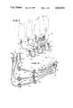
- FIG. 1is a perspective view of the present invention in accordance with its use as providing a fluid path
- FIG. 2is a perspective view configured in accordance with the present invention.
- FIG. 3is a sectional view of a portion of the present invention.
- FIG. 4is a sectional view of another portion of the present invention.
- FIG. 1shows the device 10 in position for use with the HIGH SPEED BULK COMPOUNDER
- FIG. 2shows the device 10 as it is removed from its sterile package.
- Supply containers 12, 14 and 16shown in phantom in FIG. 1, are fluidly connected with a receiving container 18 (also shown in phantom) by device 10.
- the supply and receiving containers which are shown in phantommay be flexible plastic bags of the type marketed by Travenol Laboratories, Inc. of Deerfield, Ill. under the register trademark VIAFLEX.
- the device 10provides a sterile fluid path from each supply container to a common junction block 20, where a receiving container can be placed in fluid communication therewith.
- the solutions to be compoundedare transferred from the supply containers to the receiving container by peristaltic pumps 22, 24 and 26 (shown in phantom).
- the peristaltic pumps 22, 24 and 26effect fluid flow from the supply containers 12, 14 and 16 through the device 10 to the receiving container 18 by movement of rotatable rollers 28 of each pump which compress respective tensioned wall portions 30, 30' or 30" of the fluid path in contact therewith, forcing the fluid therein forward.
- the portion 30, 30' and 30" of the fluid paths of device 10 in contact with each respective pumpis an elastomeric body or pump tubing from about four inches (10.16 centimeters) to about six inches (15.24 centimeters) long, preferably five inches (12.7 centimeters) long, capable of being put in tension.
- the ends of each pump tubing 30, 30' and 30"are connected to respctive inlet and exit pump fittings 32, 32' and 32" and 34, 34' and 34" respectively, which are operatively fixed in position to maintain the pump tubing in tension, such as placed within inlet and exit slots of a pump housing (not shown).
- the fluid paths of device 10start with fluid connectors 36, 36' and 36'.
- the tips of the fluid connectors 36, 36' and 36"are adapted to be inserted into the supply containers 12, 14 and 16 respectively and prior to their use are covered with a protective sheath 38, 38' and 38" (FIG. 2) to prevent contamination of the connectors and the fluid paths.
- Each fluid connectoris sealingly connected to a respective fluid line 40, 40' and 40", such as vinyl tubing or the like which are sealingly connected to a respective inlet pump fitting 32, 32' and 32".
- Further fluid lines 42, 42' and 42"are each sealingly connected to a respective exit pump fitting 34, 34' and 34" to connect it with the common junction block 20.
- the inlet and exit pump fittings 32 and 34 as seen in FIG. 4are representative of like fittings and tubings of device 10.
- the inlet and exit pump fittingshave a ribbed portion 43 around their periphery. This ribbed portion 43 facilitates their gripping to place pump tubing 30 in tension around rollers 28.
- the inlet and exit pump fittings 32 and 34are identical and have a dish shaped portion 44 at one end connected to a cylindrical portion 46 at the other end providing a shoulder portion 47.
- the shoulder portion 47bears against the inlet or exit slots of the pump housing to maintain tension in the pump tubing 30 connected thereto.
- the pump tubing 30is stretched over the cylindrical portion 46 of the fittings 32 and 34 to provide an interference fit therebetween.
- the cylindrical portion 46includes a cylindrical fluid line receiver 48 tapered along its length therein having a shoulder portion 50.
- the fluid lineis inserted into the cylindrical portion 46 through the dish shaped portion 44 until it contacts the shoulder 50.
- the lineis then sealed therein.
- the cylindrical portion 46then provides fluid communication through a hollow cylindrical portion 52.
- the fluid lines 40, 40' and 40" coupling respective fluid connectors 36, 36' and 36" to respective inlet pump fittings 32, 32' and 32"are preferably of the same length.
- the fluid lines 42, 42' and 42" coupling the exit pump fitting 34, 34' and 34" to the common junction block 20are preferably of differing lengths to accommodate differences in the spatial relation of each pump 22, 24 and 26 to the block 20.
- at least one of each set of inlet and exit pump fittingsare either numerically, color or otherwise coded to correspond to a respective coded operative position to provide proper orientation of the device 10.
- the common junction block 20is best seen in FIG. 3.
- the block 20includes a junction body 54, a top cap 56 and a membrane 58 therebetween.
- the body 54provides substantially parallel, vertically spaced tapered channels 60, 60' and 60" which are each adapted to receive a respective fluid line 42, 42' and 42" so as not to inhibit fluid flow therethrough by crimping of the lines.
- the channels 60, 60' and 60"are tapered to provide a snug fit for fluid lines 42, 42' and 42" which are sealingly connected therein.
- Ports 62, 62' and 62"provide fluid communication between a respective channel and a small volume chamber 64.
- the chamber 64is at substantially right angles to the channels and ports and is of an inverted truncated cone shape 66 leading into another more pronounced inverted truncated cone shape 68 leading into a cylindrical portion 70.
- the top cap 56is sealed, such as by welding, to the upper portion of the body 54 and secures the membrane 58 therebetween.
- the top cap 56provides a dish shaped opening 72 leading in a channel 74 which provides communication with the membrane 58.
- the membrane 58has a normally closed, resiliently deformable slit 76 which extends therethrough.
- the slit 76provides a sealed sterile fluid path for the entrance of a fluid connector or the like to provide a fluid path to the receiving container. This is accomplished by the membrane 58 deforming and closing about the connector. Upon withdrawal of the connector the membrane 58 will close upon itself immediately, thereby continuing to protect the fluid path of the device 10.
- the top cap, membrane and slitare of the type disclosed in U.S. Pat. No. 4,197,848 which issued in the names of Scott T. Garrett, Robert R. Fasana and William L. Rudzena.
- a closure or dust cover 78is provided to protect the fluid path of device 10 when not inuse.
- the cover 78includes a closure member 80, a connecting member 82 and a flexible arm 84 therebetween.
- the connecting member 82is ring-like and fits around the periphery of the upper end portion of the junction body 54.
- the top cap 56is provided with a lip 86 at its upper end portion to prevent the member 82 from becoming dislodged from the junction body 54 and to provide a sealed connection with member 80.
- the flexible arm 84connects the connecting member 82 and the closure member 80.
- the arm 84maintains the members 80 and 82 in the substantially same plane and out of the way of the functional area when not used to protect device 10, but allows easy access when needed.
- the closure member 80includes lip 88 and undercut 90 which are complemental with lip 86 of the top cap 56 to provide a sealed enclosure about the top cap 56 thereby protecting the fluid path of device 10.
- the member 80is orientated with its internal side 92 facing downward, when not used to protect device 10, to prevent any particulate matter from accumulating thereon.
- the member 80 when sealingly covering top cap 56requires the flexible arm 84 to be rotated or twisted about its axis to provide the proper orientation of the closure 80 with respect to the top cap 56.
- the member 80also includes a pull tab 94 with a raised gripping area 96 for easy grasping of the tab 94 to facilitate the uncovering of the top cap 56.
- the device 10 of the present invention hereinabove describedprovides a unitized, sterile, economical fluid path between a plurality of solution containers containing solutions to be transferred to a receiving container.
- the deviceis especially adapted for use with the HIGH SPEED BULK COMPOUNDER to provide a fast, efficient, precise, sterile way of compounding solutions. Further, the device 10 provides the proper orientation of the device with respect to the compounder to prevent errors.
Landscapes
- Health & Medical Sciences (AREA)
- Nutrition Science (AREA)
- Chemical & Material Sciences (AREA)
- Medicinal Chemistry (AREA)
- Pharmacology & Pharmacy (AREA)
- Life Sciences & Earth Sciences (AREA)
- Animal Behavior & Ethology (AREA)
- General Health & Medical Sciences (AREA)
- Public Health (AREA)
- Veterinary Medicine (AREA)
- Reciprocating Pumps (AREA)
Abstract
Description
Claims (29)
Priority Applications (1)
| Application Number | Priority Date | Filing Date | Title |
|---|---|---|---|
| US06/648,630US4823833A (en) | 1982-06-24 | 1984-09-11 | Fluid communication device |
Applications Claiming Priority (2)
| Application Number | Priority Date | Filing Date | Title |
|---|---|---|---|
| US39178482A | 1982-06-24 | 1982-06-24 | |
| US06/648,630US4823833A (en) | 1982-06-24 | 1984-09-11 | Fluid communication device |
Related Parent Applications (1)
| Application Number | Title | Priority Date | Filing Date |
|---|---|---|---|
| US39178482AContinuation | 1982-06-24 | 1982-06-24 |
Publications (1)
| Publication Number | Publication Date |
|---|---|
| US4823833Atrue US4823833A (en) | 1989-04-25 |
Family
ID=27013625
Family Applications (1)
| Application Number | Title | Priority Date | Filing Date |
|---|---|---|---|
| US06/648,630Expired - LifetimeUS4823833A (en) | 1982-06-24 | 1984-09-11 | Fluid communication device |
Country Status (1)
| Country | Link |
|---|---|
| US (1) | US4823833A (en) |
Cited By (71)
| Publication number | Priority date | Publication date | Assignee | Title |
|---|---|---|---|---|
| US5232439A (en)* | 1992-11-02 | 1993-08-03 | Infusion Technologies Corporation | Method for pumping fluid from a flexible, variable geometry reservoir |
| US5269350A (en)* | 1988-10-20 | 1993-12-14 | Galloway Company | Aseptic fluid transfer apparatus and methods |
| US5334182A (en)* | 1992-09-02 | 1994-08-02 | Perry Creek Group Corporation | Pulmonary artery catheter monitoring bridge |
| US5342313A (en)* | 1992-11-02 | 1994-08-30 | Infusion Technologies Corporation | Fluid pump for a flexible, variable geometry reservoir |
| US5429485A (en)* | 1992-12-18 | 1995-07-04 | Minnesota Mining And Manufacturing Company | Plural inlet pumping cassette with integral manifold |
| US5583052A (en)* | 1994-05-23 | 1996-12-10 | The Liposome Company, Inc. | Formulation preparation device |
| US5614412A (en)* | 1995-09-08 | 1997-03-25 | Smith; Stephen L. | Apparatus for carrying flexible containers and method of transferring fluids to containers |
| US5658260A (en) | 1988-01-25 | 1997-08-19 | Baxter International Inc. | Bayonet lock cannula for pre-slit y-site |
| US5776125A (en) | 1991-07-30 | 1998-07-07 | Baxter International Inc. | Needleless vial access device |
| US5792126A (en)* | 1995-05-04 | 1998-08-11 | Waterstone Medical, Inc. | Fluid collection canister for use in medical procedures |
| US5797897A (en) | 1988-01-25 | 1998-08-25 | Baxter International Inc. | Pre-slit injection site and tapered cannula |
| US5957898A (en) | 1997-05-20 | 1999-09-28 | Baxter International Inc. | Needleless connector |
| US5993420A (en)* | 1995-03-06 | 1999-11-30 | Sabratek Corporation | Cassette for an infusion pump |
| US6074366A (en)* | 1998-01-16 | 2000-06-13 | Tandem Medical Inc. | Medication delivery apparatus |
| US6193697B1 (en) | 1987-03-17 | 2001-02-27 | Baxter International Inc. | Pre-slit injection site and tapered cannula |
| US6213996B1 (en) | 1988-01-25 | 2001-04-10 | Baxter International Inc. | Pre-slit injection site and tapered cannula |
| US6261282B1 (en) | 1997-05-20 | 2001-07-17 | Baxter International Inc. | Needleless connector |
| US6306117B1 (en)* | 1993-10-28 | 2001-10-23 | Medrad, Inc. | Multi-patient fluid dispensing |
| US6428518B1 (en) | 1999-11-05 | 2002-08-06 | Tandem Medical | Medication delivery container |
| US6450215B1 (en) | 2000-09-29 | 2002-09-17 | Charter Medical, Ltd. | Apparatus and method for filling bags |
| US20030158508A1 (en)* | 2001-12-31 | 2003-08-21 | Arizona Medical Devices, Llc | Pharmaceutical compounding systems and methods with enhanced order entry and information management capabilities for single and/or multiple users and/or a network management capabilities for single and/or multiple users and/or a network |
| US20040068238A1 (en)* | 2002-10-04 | 2004-04-08 | Utterberg David S. | Injection site for male luer or other tubular connector |
| US20040068239A1 (en)* | 2002-10-04 | 2004-04-08 | Utterberg David S. | Injection site for male luer or other tubular connector |
| US20040073174A1 (en)* | 1991-12-18 | 2004-04-15 | Lopez George A. | Medical valve and method of use |
| US6726655B1 (en) | 1999-11-05 | 2004-04-27 | Tandem Medical | Medication delivery system |
| US20040087888A1 (en)* | 2001-12-31 | 2004-05-06 | Digianfilippo Aleandro | Pharmaceutical compounding systems and methods and information management system for same |
| US20040162488A1 (en)* | 1994-09-21 | 2004-08-19 | Medrad, Inc. | Patient specific dosing contrast delivery systems and methods |
| US20040186414A1 (en)* | 2003-02-03 | 2004-09-23 | Maurice Behague | Collection bag system with preformed loop |
| US20040199075A1 (en)* | 1993-10-28 | 2004-10-07 | Medrad, Inc. | Total system for contrast delivery |
| US20040249336A1 (en)* | 1997-03-03 | 2004-12-09 | Faries Durward I. | Temperature sensing device for selectively measuring temperature at desired locations along an intravenous fluid line |
| US20050086008A1 (en)* | 2001-12-31 | 2005-04-21 | Digianfilippo Aleandro | Apparatus and method for transferring data to a pharmaceutical compounding system |
| US20050126652A1 (en)* | 2003-12-04 | 2005-06-16 | Digianfilippo Aleandro | Bulk compounder manifold |
| US20050142013A1 (en)* | 2001-12-17 | 2005-06-30 | Faries Durward I.Jr. | Method and apparatus for heating solutions within intravenous lines to desired temperatures during infusion |
| US20060054241A1 (en)* | 2004-09-16 | 2006-03-16 | Joel Bartholomew | By-pass line connector for compounding system |
| US20060253075A1 (en)* | 2001-03-12 | 2006-11-09 | Faries Durward I Jr | Method and apparatus for controlling pressurized infusion and temperature of infused liquids |
| US20070106243A1 (en)* | 2005-10-27 | 2007-05-10 | Faries Durward I Jr | Method and apparatus to indicate prior use of a medical item |
| US20070215018A1 (en)* | 2006-03-20 | 2007-09-20 | Faries Durward I Jr | Method and Apparatus for Securely Storing Medical Items Within a Thermal Treatment System |
| US20080147016A1 (en)* | 1997-03-03 | 2008-06-19 | Faries Durward I | Method and Apparatus for Pressure Infusion and Temperature Control of Infused Liquids |
| US20080205481A1 (en)* | 2007-02-22 | 2008-08-28 | Faries Durward I | Method and Apparatus for Measurement and Control of Temperature for Infused Liquids |
| US7611504B1 (en) | 2004-03-09 | 2009-11-03 | Patented Medical Solutions Llc | Method and apparatus for facilitating injection of medication into an intravenous fluid line while maintaining sterility of infused fluids |
| US20100113887A1 (en)* | 2006-12-29 | 2010-05-06 | Medrad, Inc. | Patient-based parameter generation systems for medical injection procedures |
| US20100114064A1 (en)* | 2008-11-03 | 2010-05-06 | Medrad, Inc. | Mitigation of contrast-induced nephropathy |
| USD622378S1 (en)* | 2009-03-06 | 2010-08-24 | Nipro Corporation | Medical stopcock |
| US7925330B2 (en) | 2004-11-24 | 2011-04-12 | Medrad, Inc. | Devices, systems and methods for determining parameters of one or more phases of an injection procedure |
| US8002765B2 (en) | 1995-12-15 | 2011-08-23 | Icu Medical, Inc. | Medical valve with fluid escape space |
| US8821011B2 (en) | 1999-03-30 | 2014-09-02 | Medical Solutions, Inc. | Method and apparatus for monitoring temperature of intravenously delivered fluids and other medical items |
| US9008759B2 (en) | 2007-07-17 | 2015-04-14 | Bayer Medical Care Inc. | Devices and systems for determination of parameters for a procedure, for estimation of cardiopulmonary function and for fluid delivery |
| US9211381B2 (en) | 2012-01-20 | 2015-12-15 | Medical Solutions, Inc. | Method and apparatus for controlling temperature of medical liquids |
| US9616166B2 (en) | 2004-11-16 | 2017-04-11 | Bayer Healthcare Llc | Systems and methods of determining injection protocols for diagnostic imaging procedures |
| US9656029B2 (en) | 2013-02-15 | 2017-05-23 | Medical Solutions, Inc. | Plural medical item warming system and method for warming a plurality of medical items to desired temperatures |
| US9700672B2 (en) | 2011-09-21 | 2017-07-11 | Bayer Healthcare Llc | Continuous multi-fluid pump device, drive and actuating system and method |
| US9861733B2 (en) | 2012-03-23 | 2018-01-09 | Nxstage Medical Inc. | Peritoneal dialysis systems, devices, and methods |
| US9889239B2 (en) | 2007-03-23 | 2018-02-13 | Allegiance Corporation | Fluid collection and disposal system and related methods |
| US9907897B2 (en) | 2011-03-23 | 2018-03-06 | Nxstage Medical, Inc. | Peritoneal dialysis systems, devices, and methods |
| US9949704B2 (en) | 2012-05-14 | 2018-04-24 | Bayer Healthcare Llc | Systems and methods for determination of pharmaceutical fluid injection protocols based on x-ray tube voltage |
| US9959389B2 (en) | 2010-06-24 | 2018-05-01 | Bayer Healthcare Llc | Modeling of pharmaceutical propagation and parameter generation for injection protocols |
| US10252856B2 (en) | 2007-03-23 | 2019-04-09 | Allegiance Corporation | Fluid collection and disposal system having interchangeable collection and other features and methods relating thereof |
| US10507319B2 (en) | 2015-01-09 | 2019-12-17 | Bayer Healthcare Llc | Multiple fluid delivery system with multi-use disposable set and features thereof |
| US10898638B2 (en) | 2016-03-03 | 2021-01-26 | Bayer Healthcare Llc | System and method for improved fluid delivery in multi-fluid injector systems |
| US11141535B2 (en) | 2017-08-31 | 2021-10-12 | Bayer Healthcare Llc | Fluid path impedance assessment for improving fluid delivery performance |
| US11207454B2 (en) | 2018-02-28 | 2021-12-28 | Nxstage Medical, Inc. | Fluid preparation and treatment devices methods and systems |
| US11278853B2 (en) | 2013-03-13 | 2022-03-22 | Bayer Healthcare Llc | Method for controlling fluid accuracy and backflow compensation |
| US11478581B2 (en) | 2017-08-31 | 2022-10-25 | Bayer Healthcare Llc | Fluid injector system volume compensation system and method |
| US11598664B2 (en) | 2017-08-31 | 2023-03-07 | Bayer Healthcare Llc | Injector pressure calibration system and method |
| US11779702B2 (en) | 2017-08-31 | 2023-10-10 | Bayer Healthcare Llc | Method for dynamic pressure control in a fluid injector system |
| US11786652B2 (en) | 2017-08-31 | 2023-10-17 | Bayer Healthcare Llc | System and method for drive member position and fluid injector system mechanical calibration |
| US12048791B2 (en) | 2017-06-24 | 2024-07-30 | Nxstage Medical, Inc. | Peritoneal dialysis fluid preparation and/or treatment devices methods and systems |
| US12208239B2 (en) | 2018-08-28 | 2025-01-28 | Bayer Healthcare Llc | Fluid injector system, method of preventing fluid backflow, and computer program product |
| US12251544B2 (en) | 2018-04-19 | 2025-03-18 | Bayer Healthcare Llc | System and method for air detection in fluid injector |
| US12263326B2 (en) | 2016-11-14 | 2025-04-01 | Bayer Healthcare Llc | Methods and systems for verifying the contents of a syringe used for medical fluid delivery |
| US12427249B2 (en) | 2018-08-28 | 2025-09-30 | Bayer Healthcare Llc | Fluid injector system with improved ratio performance |
Citations (16)
| Publication number | Priority date | Publication date | Assignee | Title |
|---|---|---|---|---|
| US1686003A (en)* | 1925-04-03 | 1928-10-02 | Arnold H Hottinger | Spraying device |
| US1848024A (en)* | 1931-11-23 | 1932-03-01 | Norris T Owen | Apparatus for use in blood transfusion, intravenous medication and the like |
| FR1087062A (en)* | 1953-11-10 | 1955-02-18 | Funnel for the introduction of liquid, pasty, pulverulent or granular products into containers | |
| US3565286A (en)* | 1968-10-18 | 1971-02-23 | Cryogenic Technology Inc | Liquid programming and pumping apparatus |
| US3749285A (en)* | 1971-09-13 | 1973-07-31 | Haemonetics Corp | Programmed liquid delivery system |
| US3851646A (en)* | 1973-04-13 | 1974-12-03 | Sarns Inc | Connector for open heart surgery |
| US3941126A (en)* | 1974-08-08 | 1976-03-02 | Dietrich Joseph W | Apparatus for long term intravenous administration of diluted incompatible multiple medications |
| US4006847A (en)* | 1975-10-23 | 1977-02-08 | Dooley Dynamics, Inc. | Dispensing apparatus |
| US4036357A (en)* | 1976-01-14 | 1977-07-19 | John Cas Czelen | Contact lens cases |
| US4132225A (en)* | 1976-11-18 | 1979-01-02 | Hynson, Westcott & Dunning, Inc. | Micro blood collector |
| US4143853A (en)* | 1977-07-14 | 1979-03-13 | Metatech Corporation | Valve for use with a catheter or the like |
| US4150673A (en)* | 1977-02-03 | 1979-04-24 | Pharmachem Corporation | Coded entry system for blood bag |
| US4191183A (en)* | 1977-10-31 | 1980-03-04 | Barry Mendelson | Mixing chamber for use in plural medical liquid intravenous administration set |
| US4197848A (en)* | 1978-01-06 | 1980-04-15 | Baxter Travenol Laboratories, Inc. | Closed urinary irrigation site |
| US4296785A (en)* | 1979-07-09 | 1981-10-27 | Mallinckrodt, Inc. | System for generating and containerizing radioisotopes |
| US4347874A (en)* | 1980-10-02 | 1982-09-07 | Sullivan James J | High speed sterile fluid transfer unit |
- 1984
- 1984-09-11USUS06/648,630patent/US4823833A/ennot_activeExpired - Lifetime
Patent Citations (16)
| Publication number | Priority date | Publication date | Assignee | Title |
|---|---|---|---|---|
| US1686003A (en)* | 1925-04-03 | 1928-10-02 | Arnold H Hottinger | Spraying device |
| US1848024A (en)* | 1931-11-23 | 1932-03-01 | Norris T Owen | Apparatus for use in blood transfusion, intravenous medication and the like |
| FR1087062A (en)* | 1953-11-10 | 1955-02-18 | Funnel for the introduction of liquid, pasty, pulverulent or granular products into containers | |
| US3565286A (en)* | 1968-10-18 | 1971-02-23 | Cryogenic Technology Inc | Liquid programming and pumping apparatus |
| US3749285A (en)* | 1971-09-13 | 1973-07-31 | Haemonetics Corp | Programmed liquid delivery system |
| US3851646A (en)* | 1973-04-13 | 1974-12-03 | Sarns Inc | Connector for open heart surgery |
| US3941126A (en)* | 1974-08-08 | 1976-03-02 | Dietrich Joseph W | Apparatus for long term intravenous administration of diluted incompatible multiple medications |
| US4006847A (en)* | 1975-10-23 | 1977-02-08 | Dooley Dynamics, Inc. | Dispensing apparatus |
| US4036357A (en)* | 1976-01-14 | 1977-07-19 | John Cas Czelen | Contact lens cases |
| US4132225A (en)* | 1976-11-18 | 1979-01-02 | Hynson, Westcott & Dunning, Inc. | Micro blood collector |
| US4150673A (en)* | 1977-02-03 | 1979-04-24 | Pharmachem Corporation | Coded entry system for blood bag |
| US4143853A (en)* | 1977-07-14 | 1979-03-13 | Metatech Corporation | Valve for use with a catheter or the like |
| US4191183A (en)* | 1977-10-31 | 1980-03-04 | Barry Mendelson | Mixing chamber for use in plural medical liquid intravenous administration set |
| US4197848A (en)* | 1978-01-06 | 1980-04-15 | Baxter Travenol Laboratories, Inc. | Closed urinary irrigation site |
| US4296785A (en)* | 1979-07-09 | 1981-10-27 | Mallinckrodt, Inc. | System for generating and containerizing radioisotopes |
| US4347874A (en)* | 1980-10-02 | 1982-09-07 | Sullivan James J | High speed sterile fluid transfer unit |
Cited By (167)
| Publication number | Priority date | Publication date | Assignee | Title |
|---|---|---|---|---|
| US6193697B1 (en) | 1987-03-17 | 2001-02-27 | Baxter International Inc. | Pre-slit injection site and tapered cannula |
| US6261266B1 (en) | 1988-01-25 | 2001-07-17 | Baxter International Inc. | Pre-slit injection site and tapered cannula |
| US6213996B1 (en) | 1988-01-25 | 2001-04-10 | Baxter International Inc. | Pre-slit injection site and tapered cannula |
| US6605076B1 (en) | 1988-01-25 | 2003-08-12 | Baxter International Inc. | Pre-slit injection site and tapered cannula |
| US6569125B2 (en) | 1988-01-25 | 2003-05-27 | Baxter International Inc | Pre-slit injection site and tapered cannula |
| US6447498B1 (en) | 1988-01-25 | 2002-09-10 | Baxter International Inc. | Pre-slit injection site and tapered cannula |
| US6217568B1 (en) | 1988-01-25 | 2001-04-17 | Edwards Lifesciences Corporation | Preslit injection site and tapered cannula for blood sampling |
| US5658260A (en) | 1988-01-25 | 1997-08-19 | Baxter International Inc. | Bayonet lock cannula for pre-slit y-site |
| US5871500A (en) | 1988-01-25 | 1999-02-16 | Baxter International Inc. | Pre-slit injection site and tapered cannula |
| US5797897A (en) | 1988-01-25 | 1998-08-25 | Baxter International Inc. | Pre-slit injection site and tapered cannula |
| US5269350A (en)* | 1988-10-20 | 1993-12-14 | Galloway Company | Aseptic fluid transfer apparatus and methods |
| US5776125A (en) | 1991-07-30 | 1998-07-07 | Baxter International Inc. | Needleless vial access device |
| US20040073174A1 (en)* | 1991-12-18 | 2004-04-15 | Lopez George A. | Medical valve and method of use |
| US7717885B2 (en) | 1991-12-18 | 2010-05-18 | Icu Medical, Inc. | Medical valve and method of use |
| US7722576B2 (en) | 1991-12-18 | 2010-05-25 | Icu Medical, Inc. | Medical valve and method of use |
| US7722575B2 (en) | 1991-12-18 | 2010-05-25 | Icu Medical, Inc. | Medical valve and method of use |
| US20040243070A1 (en)* | 1991-12-18 | 2004-12-02 | Lopez George A. | Medical valve and method of use |
| US7717883B2 (en) | 1991-12-18 | 2010-05-18 | Icu Medical, Inc. | Medical valve and method of use |
| US7713247B2 (en) | 1991-12-18 | 2010-05-11 | Icu Medical, Inc. | Medical valve and method of use |
| US7717886B2 (en) | 1991-12-18 | 2010-05-18 | Icu Medical, Inc. | Medical valve and method of use |
| US7717887B2 (en) | 1991-12-18 | 2010-05-18 | Icu Medical, Inc. | Medical valve and method of use |
| US7717884B2 (en) | 1991-12-18 | 2010-05-18 | Icu Medical, Inc. | Medical valve and method of use |
| US7713248B2 (en) | 1991-12-18 | 2010-05-11 | Icu Medical, Inc. | Medical valve and method of use |
| US7713249B2 (en) | 1991-12-18 | 2010-05-11 | Icu Medical, Inc. | Medical valve and method of use |
| US5334182A (en)* | 1992-09-02 | 1994-08-02 | Perry Creek Group Corporation | Pulmonary artery catheter monitoring bridge |
| US5232439A (en)* | 1992-11-02 | 1993-08-03 | Infusion Technologies Corporation | Method for pumping fluid from a flexible, variable geometry reservoir |
| US5342313A (en)* | 1992-11-02 | 1994-08-30 | Infusion Technologies Corporation | Fluid pump for a flexible, variable geometry reservoir |
| US5429485A (en)* | 1992-12-18 | 1995-07-04 | Minnesota Mining And Manufacturing Company | Plural inlet pumping cassette with integral manifold |
| US7427281B2 (en) | 1993-10-28 | 2008-09-23 | Medrad, Inc. | Method of delivering fluid mixtures to multiple patients |
| US6306117B1 (en)* | 1993-10-28 | 2001-10-23 | Medrad, Inc. | Multi-patient fluid dispensing |
| US20040199075A1 (en)* | 1993-10-28 | 2004-10-07 | Medrad, Inc. | Total system for contrast delivery |
| US6901283B2 (en) | 1993-10-28 | 2005-05-31 | Medrad, Inc. | Adjusting a condition of a fluid medium to produce an image of a patient |
| US5583052A (en)* | 1994-05-23 | 1996-12-10 | The Liposome Company, Inc. | Formulation preparation device |
| US20080045834A1 (en)* | 1994-09-21 | 2008-02-21 | Medrad, Inc. | System and method for delivering fluids to a balloon catheter |
| US7313431B2 (en) | 1994-09-21 | 2007-12-25 | Medrad, Inc. | System and method for inflating a balloon catheter and delivering fluid media to a patient |
| US20040162488A1 (en)* | 1994-09-21 | 2004-08-19 | Medrad, Inc. | Patient specific dosing contrast delivery systems and methods |
| US5993420A (en)* | 1995-03-06 | 1999-11-30 | Sabratek Corporation | Cassette for an infusion pump |
| US5792126A (en)* | 1995-05-04 | 1998-08-11 | Waterstone Medical, Inc. | Fluid collection canister for use in medical procedures |
| US5614412A (en)* | 1995-09-08 | 1997-03-25 | Smith; Stephen L. | Apparatus for carrying flexible containers and method of transferring fluids to containers |
| US8002765B2 (en) | 1995-12-15 | 2011-08-23 | Icu Medical, Inc. | Medical valve with fluid escape space |
| US20040249336A1 (en)* | 1997-03-03 | 2004-12-09 | Faries Durward I. | Temperature sensing device for selectively measuring temperature at desired locations along an intravenous fluid line |
| US8920387B2 (en) | 1997-03-03 | 2014-12-30 | Medical Solutions, Inc. | Method and apparatus for pressure infusion and temperature control of infused liquids |
| US8313462B2 (en) | 1997-03-03 | 2012-11-20 | Medical Solutions, Inc. | Method and apparatus for pressure infusion and temperature control of infused liquids |
| US20080147016A1 (en)* | 1997-03-03 | 2008-06-19 | Faries Durward I | Method and Apparatus for Pressure Infusion and Temperature Control of Infused Liquids |
| US7942851B2 (en) | 1997-03-03 | 2011-05-17 | Medical Solutions, Inc. | Method and apparatus for pressure infusion and temperature control of infused liquids |
| US7540864B2 (en) | 1997-03-03 | 2009-06-02 | Medical Solutions, Inc. | Temperature sensing device for selectively measuring temperature at desired locations along an intravenous fluid line |
| US6669681B2 (en) | 1997-05-20 | 2003-12-30 | Baxter International Inc. | Needleless connector |
| US6344033B1 (en) | 1997-05-20 | 2002-02-05 | Baxter International, Inc. | Needleless connector |
| US6261282B1 (en) | 1997-05-20 | 2001-07-17 | Baxter International Inc. | Needleless connector |
| US5957898A (en) | 1997-05-20 | 1999-09-28 | Baxter International Inc. | Needleless connector |
| USRE43142E1 (en) | 1997-05-20 | 2012-01-24 | Baxter International, Inc. | Needleless connector |
| US6074366A (en)* | 1998-01-16 | 2000-06-13 | Tandem Medical Inc. | Medication delivery apparatus |
| US6416496B1 (en) | 1998-01-16 | 2002-07-09 | Tandem Medical, Inc. | Medication delivery apparatus |
| US6146360A (en)* | 1998-01-16 | 2000-11-14 | Tandem Medical, Inc. | Medication delivery apparatus |
| US8821011B2 (en) | 1999-03-30 | 2014-09-02 | Medical Solutions, Inc. | Method and apparatus for monitoring temperature of intravenously delivered fluids and other medical items |
| US6726655B1 (en) | 1999-11-05 | 2004-04-27 | Tandem Medical | Medication delivery system |
| US6428518B1 (en) | 1999-11-05 | 2002-08-06 | Tandem Medical | Medication delivery container |
| US6450215B1 (en) | 2000-09-29 | 2002-09-17 | Charter Medical, Ltd. | Apparatus and method for filling bags |
| US9119912B2 (en) | 2001-03-12 | 2015-09-01 | Medical Solutions, Inc. | Method and apparatus for controlling pressurized infusion and temperature of infused liquids |
| US20060253075A1 (en)* | 2001-03-12 | 2006-11-09 | Faries Durward I Jr | Method and apparatus for controlling pressurized infusion and temperature of infused liquids |
| US9492624B2 (en) | 2001-12-17 | 2016-11-15 | Medical Solutions, Inc. | Method and apparatus for heating solutions within intravenous lines to desired temperatures during infusion |
| US8226605B2 (en) | 2001-12-17 | 2012-07-24 | Medical Solutions, Inc. | Method and apparatus for heating solutions within intravenous lines to desired temperatures during infusion |
| US8920372B2 (en) | 2001-12-17 | 2014-12-30 | Medical Solutions, Inc. | Method and apparatus for heating solutions within intravenous lines to desired temperatures during infusion |
| US20050142013A1 (en)* | 2001-12-17 | 2005-06-30 | Faries Durward I.Jr. | Method and apparatus for heating solutions within intravenous lines to desired temperatures during infusion |
| US7317967B2 (en) | 2001-12-31 | 2008-01-08 | B. Braun Medical Inc. | Apparatus and method for transferring data to a pharmaceutical compounding system |
| US7343224B2 (en) | 2001-12-31 | 2008-03-11 | B. Braun Medical Inc. | Pharmaceutical compounding systems and methods and information management system for same |
| US20050086008A1 (en)* | 2001-12-31 | 2005-04-21 | Digianfilippo Aleandro | Apparatus and method for transferring data to a pharmaceutical compounding system |
| US20060133966A1 (en)* | 2001-12-31 | 2006-06-22 | Digianfilippo Aleandro | Transfer set for use with a pharmaceutical compounder |
| US20030158508A1 (en)* | 2001-12-31 | 2003-08-21 | Arizona Medical Devices, Llc | Pharmaceutical compounding systems and methods with enhanced order entry and information management capabilities for single and/or multiple users and/or a network management capabilities for single and/or multiple users and/or a network |
| US7194336B2 (en) | 2001-12-31 | 2007-03-20 | B. Braun Medical Inc. | Pharmaceutical compounding systems and methods with enhanced order entry and information management capabilities for single and/or multiple users and/or a network management capabilities for single and/or multiple users and/or a network |
| US20040087888A1 (en)* | 2001-12-31 | 2004-05-06 | Digianfilippo Aleandro | Pharmaceutical compounding systems and methods and information management system for same |
| US7171992B2 (en) | 2001-12-31 | 2007-02-06 | B. Braun Medical Inc. | Pharmaceutical compounder |
| US20060136081A1 (en)* | 2001-12-31 | 2006-06-22 | Digianfilippo Aleandro | Pharmaceutical compounder and information management system |
| US20060130927A1 (en)* | 2001-12-31 | 2006-06-22 | Digianfilippo Aleandro | Pharmaceutical compounder |
| US7025744B2 (en) | 2002-10-04 | 2006-04-11 | Dsu Medical Corporation | Injection site for male luer or other tubular connector |
| US8647312B2 (en) | 2002-10-04 | 2014-02-11 | Nxstage Medical, Inc. | Injection site for male luer or other tubular connector |
| US8377039B2 (en) | 2002-10-04 | 2013-02-19 | Nxstage Medical, Inc. | Injection site for male luer or other tubular connector |
| US20040068238A1 (en)* | 2002-10-04 | 2004-04-08 | Utterberg David S. | Injection site for male luer or other tubular connector |
| US20040068239A1 (en)* | 2002-10-04 | 2004-04-08 | Utterberg David S. | Injection site for male luer or other tubular connector |
| US20080125897A1 (en)* | 2002-12-31 | 2008-05-29 | B. Braun Medical Inc. | Method for transferring data to a pharmaceutical compounding system |
| US7503901B2 (en)* | 2003-02-03 | 2009-03-17 | Macopharma | Collection bag system with preformed loop |
| US20040186414A1 (en)* | 2003-02-03 | 2004-09-23 | Maurice Behague | Collection bag system with preformed loop |
| US7036537B2 (en) | 2003-12-04 | 2006-05-02 | B. Braun Medical Inc. | Bulk compounder manifold |
| US20060070684A1 (en)* | 2003-12-04 | 2006-04-06 | Digianfilippo Aleandro | Bulk compounder manifold |
| US6951228B2 (en) | 2003-12-04 | 2005-10-04 | B Braun Medical Inc. | Bulk compounder manifold |
| US7252122B2 (en) | 2003-12-04 | 2007-08-07 | B. Braun Medical Inc. | Bulk compounder manifold |
| US20050126652A1 (en)* | 2003-12-04 | 2005-06-16 | Digianfilippo Aleandro | Bulk compounder manifold |
| US8845586B2 (en) | 2004-03-09 | 2014-09-30 | Patented Medical Solutions Llc | Method and apparatus for facilitating injection of medication into an intravenous fluid line while maintaining sterility of infused fluids |
| US7611504B1 (en) | 2004-03-09 | 2009-11-03 | Patented Medical Solutions Llc | Method and apparatus for facilitating injection of medication into an intravenous fluid line while maintaining sterility of infused fluids |
| US7204277B2 (en) | 2004-09-16 | 2007-04-17 | B. Braun Medical Inc. | By-pass line connector for compounding system |
| US20080283146A1 (en)* | 2004-09-16 | 2008-11-20 | B.Braun Medical, Inc. | By-pass line connector for compounding system |
| US20060054241A1 (en)* | 2004-09-16 | 2006-03-16 | Joel Bartholomew | By-pass line connector for compounding system |
| US20100032052A1 (en)* | 2004-09-16 | 2010-02-11 | B. Braun Medical, Inc. | By-pass line connector for compounding system |
| US7490636B2 (en) | 2004-09-16 | 2009-02-17 | B. Braun Medical Inc. | By-pass line connector for compounding system |
| US7836920B2 (en) | 2004-09-16 | 2010-11-23 | B. Braun Medical, Inc. | By-pass line connector for compounding system |
| US20070151618A1 (en)* | 2004-09-16 | 2007-07-05 | Joel Bartholomew | By-pass line connector for compounding system |
| US7726361B2 (en) | 2004-09-16 | 2010-06-01 | B. Braun Medical, Inc. | By-pass line connector for compounding system |
| US20070151626A1 (en)* | 2004-09-16 | 2007-07-05 | Joel Bartholomew | By-pass line connector for compounding system |
| US7415994B2 (en) | 2004-09-16 | 2008-08-26 | B.Braun Medical, Inc. | By-pass line connector for compounding system |
| US9616166B2 (en) | 2004-11-16 | 2017-04-11 | Bayer Healthcare Llc | Systems and methods of determining injection protocols for diagnostic imaging procedures |
| US9950107B2 (en) | 2004-11-24 | 2018-04-24 | Bayer Healthcare Llc | Systems and methods for managing workflow for injection procedures |
| US7925330B2 (en) | 2004-11-24 | 2011-04-12 | Medrad, Inc. | Devices, systems and methods for determining parameters of one or more phases of an injection procedure |
| US10166326B2 (en) | 2004-11-24 | 2019-01-01 | Bayer Healthcare Llc | Devices, systems and methods for determining parameters of one or more phases of an injection procedure |
| US9238099B2 (en) | 2004-11-24 | 2016-01-19 | Bayer Healthcare Llc | System and apparatus for modeling pressures generated during an injection procedure |
| US8444599B2 (en) | 2005-10-27 | 2013-05-21 | Patented Medical Solutions, Llc | Method and apparatus to indicate prior use of a medical item |
| US20070106243A1 (en)* | 2005-10-27 | 2007-05-10 | Faries Durward I Jr | Method and apparatus to indicate prior use of a medical item |
| US8636691B2 (en) | 2005-10-27 | 2014-01-28 | Patented Medical Solutions, Llc | Method and apparatus to indicate prior use of a medical item |
| US7740611B2 (en) | 2005-10-27 | 2010-06-22 | Patented Medical Solutions, Llc | Method and apparatus to indicate prior use of a medical item |
| US20100222762A1 (en)* | 2005-10-27 | 2010-09-02 | Faries Jr Durward I | Method and Apparatus to Indicate Prior Use of a Medical Item |
| US20100222763A1 (en)* | 2005-10-27 | 2010-09-02 | Faries Jr Durward I | Method and Apparatus to Indicate Prior Use of a Medical Item |
| US8487738B2 (en) | 2006-03-20 | 2013-07-16 | Medical Solutions, Inc. | Method and apparatus for securely storing medical items within a thermal treatment system |
| US20070215018A1 (en)* | 2006-03-20 | 2007-09-20 | Faries Durward I Jr | Method and Apparatus for Securely Storing Medical Items Within a Thermal Treatment System |
| US10463782B2 (en) | 2006-12-29 | 2019-11-05 | Bayer Healthcare Llc | Patient-based parameter generation systems for medical injection procedures |
| US9302044B2 (en) | 2006-12-29 | 2016-04-05 | Bayer Healthcare Llc | Patient-based parameter generation systems for medical injection procedures |
| US20100113887A1 (en)* | 2006-12-29 | 2010-05-06 | Medrad, Inc. | Patient-based parameter generation systems for medical injection procedures |
| US20080205481A1 (en)* | 2007-02-22 | 2008-08-28 | Faries Durward I | Method and Apparatus for Measurement and Control of Temperature for Infused Liquids |
| US8226293B2 (en) | 2007-02-22 | 2012-07-24 | Medical Solutions, Inc. | Method and apparatus for measurement and control of temperature for infused liquids |
| US9889239B2 (en) | 2007-03-23 | 2018-02-13 | Allegiance Corporation | Fluid collection and disposal system and related methods |
| US10252856B2 (en) | 2007-03-23 | 2019-04-09 | Allegiance Corporation | Fluid collection and disposal system having interchangeable collection and other features and methods relating thereof |
| US9008759B2 (en) | 2007-07-17 | 2015-04-14 | Bayer Medical Care Inc. | Devices and systems for determination of parameters for a procedure, for estimation of cardiopulmonary function and for fluid delivery |
| US20100114064A1 (en)* | 2008-11-03 | 2010-05-06 | Medrad, Inc. | Mitigation of contrast-induced nephropathy |
| US9421330B2 (en) | 2008-11-03 | 2016-08-23 | Bayer Healthcare Llc | Mitigation of contrast-induced nephropathy |
| USD622378S1 (en)* | 2009-03-06 | 2010-08-24 | Nipro Corporation | Medical stopcock |
| US9959389B2 (en) | 2010-06-24 | 2018-05-01 | Bayer Healthcare Llc | Modeling of pharmaceutical propagation and parameter generation for injection protocols |
| US11717601B2 (en) | 2011-03-23 | 2023-08-08 | Nxstage Medical, Inc. | Dialysis systems, devices, and methods |
| US10610630B2 (en) | 2011-03-23 | 2020-04-07 | Nxstage Medical, Inc. | Peritoneal dialysis systems, devices, and methods |
| US12246121B2 (en) | 2011-03-23 | 2025-03-11 | Nxstage Medical, Inc. | Peritoneal dialysis systems, devices, and methods |
| US11433169B2 (en) | 2011-03-23 | 2022-09-06 | Nxstage Medical, Inc. | Dialysis systems, devices, and methods |
| US10046100B2 (en) | 2011-03-23 | 2018-08-14 | Nxstage Medical, Inc. | Peritoneal dialysis systems, devices, and methods |
| US11135348B2 (en) | 2011-03-23 | 2021-10-05 | Nxstage Medical, Inc. | Peritoneal dialysis systems, devices, and methods |
| US11690941B2 (en) | 2011-03-23 | 2023-07-04 | Nxstage Medical, Inc. | Peritoneal dialysis systems, devices, and methods |
| US11224684B2 (en) | 2011-03-23 | 2022-01-18 | Nxstage Medical, Inc. | Peritoneal dialysis systems, devices, and methods |
| US11433170B2 (en) | 2011-03-23 | 2022-09-06 | Nxstage Medical, Inc. | Dialysis systems, devices, and methods |
| US10603424B2 (en) | 2011-03-23 | 2020-03-31 | Nxstage Medical, Inc. | Peritoneal dialysis systems, devices, and methods |
| US10688234B2 (en) | 2011-03-23 | 2020-06-23 | Nxstage Medical, Inc. | Peritoneal dialysis systems, devices, and methods |
| US10688235B2 (en) | 2011-03-23 | 2020-06-23 | Nxstage Medical, Inc. | Peritoneal dialysis systems, devices, and methods |
| US9907897B2 (en) | 2011-03-23 | 2018-03-06 | Nxstage Medical, Inc. | Peritoneal dialysis systems, devices, and methods |
| US10898630B2 (en) | 2011-03-23 | 2021-01-26 | Nxstage Medical, Inc. | Peritoneal dialysis systems, devices, and methods |
| US9700672B2 (en) | 2011-09-21 | 2017-07-11 | Bayer Healthcare Llc | Continuous multi-fluid pump device, drive and actuating system and method |
| US9764100B2 (en) | 2012-01-20 | 2017-09-19 | Medical Solutions, Inc. | Method and apparatus for controlling temperature of medical liquids |
| US9211381B2 (en) | 2012-01-20 | 2015-12-15 | Medical Solutions, Inc. | Method and apparatus for controlling temperature of medical liquids |
| US9861733B2 (en) | 2012-03-23 | 2018-01-09 | Nxstage Medical Inc. | Peritoneal dialysis systems, devices, and methods |
| US9949704B2 (en) | 2012-05-14 | 2018-04-24 | Bayer Healthcare Llc | Systems and methods for determination of pharmaceutical fluid injection protocols based on x-ray tube voltage |
| US11191501B2 (en) | 2012-05-14 | 2021-12-07 | Bayer Healthcare Llc | Systems and methods for determination of pharmaceutical fluid injection protocols based on x-ray tube voltage |
| US9656029B2 (en) | 2013-02-15 | 2017-05-23 | Medical Solutions, Inc. | Plural medical item warming system and method for warming a plurality of medical items to desired temperatures |
| US11278853B2 (en) | 2013-03-13 | 2022-03-22 | Bayer Healthcare Llc | Method for controlling fluid accuracy and backflow compensation |
| US10507319B2 (en) | 2015-01-09 | 2019-12-17 | Bayer Healthcare Llc | Multiple fluid delivery system with multi-use disposable set and features thereof |
| US12201802B2 (en) | 2015-01-09 | 2025-01-21 | Bayer Healthcare Llc | Multiple fluid delivery system with multi-use disposable set and features thereof |
| US11491318B2 (en) | 2015-01-09 | 2022-11-08 | Bayer Healthcare Llc | Multiple fluid delivery system with multi-use disposable set and features thereof |
| US10898638B2 (en) | 2016-03-03 | 2021-01-26 | Bayer Healthcare Llc | System and method for improved fluid delivery in multi-fluid injector systems |
| US11672902B2 (en) | 2016-03-03 | 2023-06-13 | Bayer Healthcare Llc | System and method for improved fluid delivery in multi-fluid injector systems |
| US12263326B2 (en) | 2016-11-14 | 2025-04-01 | Bayer Healthcare Llc | Methods and systems for verifying the contents of a syringe used for medical fluid delivery |
| US12048791B2 (en) | 2017-06-24 | 2024-07-30 | Nxstage Medical, Inc. | Peritoneal dialysis fluid preparation and/or treatment devices methods and systems |
| US11598664B2 (en) | 2017-08-31 | 2023-03-07 | Bayer Healthcare Llc | Injector pressure calibration system and method |
| US11779702B2 (en) | 2017-08-31 | 2023-10-10 | Bayer Healthcare Llc | Method for dynamic pressure control in a fluid injector system |
| US11786652B2 (en) | 2017-08-31 | 2023-10-17 | Bayer Healthcare Llc | System and method for drive member position and fluid injector system mechanical calibration |
| US11826553B2 (en) | 2017-08-31 | 2023-11-28 | Bayer Healthcare Llc | Fluid path impedance assessment for improving fluid delivery performance |
| US11141535B2 (en) | 2017-08-31 | 2021-10-12 | Bayer Healthcare Llc | Fluid path impedance assessment for improving fluid delivery performance |
| US12214155B2 (en) | 2017-08-31 | 2025-02-04 | Bayer Healthcare Llc | Fluid injector system volume compensation system and method |
| US11478581B2 (en) | 2017-08-31 | 2022-10-25 | Bayer Healthcare Llc | Fluid injector system volume compensation system and method |
| US11872337B2 (en) | 2018-02-28 | 2024-01-16 | Nxstage Medical, Inc. | Fluid preparation and treatment devices methods and systems |
| US11207454B2 (en) | 2018-02-28 | 2021-12-28 | Nxstage Medical, Inc. | Fluid preparation and treatment devices methods and systems |
| US11364328B2 (en) | 2018-02-28 | 2022-06-21 | Nxstage Medical, Inc. | Fluid preparation and treatment devices methods and systems |
| US12409259B2 (en) | 2018-02-28 | 2025-09-09 | Nxstage Medical, Inc. | Fluid preparation and treatment devices methods and systems |
| US12251544B2 (en) | 2018-04-19 | 2025-03-18 | Bayer Healthcare Llc | System and method for air detection in fluid injector |
| US12208239B2 (en) | 2018-08-28 | 2025-01-28 | Bayer Healthcare Llc | Fluid injector system, method of preventing fluid backflow, and computer program product |
| US12427249B2 (en) | 2018-08-28 | 2025-09-30 | Bayer Healthcare Llc | Fluid injector system with improved ratio performance |
Similar Documents
| Publication | Publication Date | Title |
|---|---|---|
| US4823833A (en) | Fluid communication device | |
| US4372100A (en) | Process and apparatus for compounding hyperalimentation solutions | |
| EP0038339B1 (en) | Process for transferring and sterilizing a solution | |
| EP0112368B1 (en) | High speed bulk compounder | |
| CA1274448A (en) | Pumping module arrangement and manifold | |
| EP0948371B1 (en) | Apparatus for administrating toxic fluid | |
| US4750643A (en) | Sterile fluid dispensing system and method | |
| US4915688A (en) | Apparatus for administering solution to a patient | |
| US4447230A (en) | Intravenous administration set assembly | |
| US4545783A (en) | Rigid medical solution container | |
| US8029023B2 (en) | Device and method for contamination-free and/or sterile sealing between at least two interconnectable connecting means | |
| CN103200895A (en) | Aseptic dispenser | |
| EP0112356B1 (en) | Fluid communication device | |
| US5069370A (en) | Large scale liquid media dispensing and supplementing system | |
| KR20050107507A (en) | Method and disposable device for sampling and distributing a liquid, for example, in sterile conditions | |
| EP0750488B1 (en) | A device and a process for aseptic mixing of liquid products | |
| JPH0414029B2 (en) | ||
| AU535674B2 (en) | Process and apparatus for transferring and sterilizing a solution |
Legal Events
| Date | Code | Title | Description |
|---|---|---|---|
| STCF | Information on status: patent grant | Free format text:PATENTED CASE | |
| FEPP | Fee payment procedure | Free format text:PAYOR NUMBER ASSIGNED (ORIGINAL EVENT CODE: ASPN); ENTITY STATUS OF PATENT OWNER: LARGE ENTITY | |
| FPAY | Fee payment | Year of fee payment:4 | |
| AS | Assignment | Owner name:CLINTEC NUTRITION COMPANY, ILLINOIS Free format text:ASSIGNMENT OF ASSIGNORS INTEREST.;ASSIGNOR:BAXTER INTERNATIONAL INC.;REEL/FRAME:006327/0970 Effective date:19921005 | |
| FPAY | Fee payment | Year of fee payment:8 | |
| AS | Assignment | Owner name:BAXTER INTERNATIONAL INC., ILLINOIS Free format text:ASSIGNMENT OF ASSIGNORS INTEREST;ASSIGNOR:CLINTEC NUTRITION COMPANY;REEL/FRAME:008239/0827 Effective date:19961001 | |
| FEPP | Fee payment procedure | Free format text:PAYER NUMBER DE-ASSIGNED (ORIGINAL EVENT CODE: RMPN); ENTITY STATUS OF PATENT OWNER: LARGE ENTITY Free format text:PAYOR NUMBER ASSIGNED (ORIGINAL EVENT CODE: ASPN); ENTITY STATUS OF PATENT OWNER: LARGE ENTITY | |
| FPAY | Fee payment | Year of fee payment:12 |