US4823552A - Failsafe electrohydraulic control system for variable displacement pump - Google Patents
Failsafe electrohydraulic control system for variable displacement pumpDownload PDFInfo
- Publication number
- US4823552A US4823552AUS07/043,829US4382987AUS4823552AUS 4823552 AUS4823552 AUS 4823552AUS 4382987 AUS4382987 AUS 4382987AUS 4823552 AUS4823552 AUS 4823552A
- Authority
- US
- United States
- Prior art keywords
- pump
- signals
- control
- condition
- valve
- Prior art date
- Legal status (The legal status is an assumption and is not a legal conclusion. Google has not performed a legal analysis and makes no representation as to the accuracy of the status listed.)
- Expired - Lifetime
Links
Images


Classifications
- F—MECHANICAL ENGINEERING; LIGHTING; HEATING; WEAPONS; BLASTING
- F04—POSITIVE - DISPLACEMENT MACHINES FOR LIQUIDS; PUMPS FOR LIQUIDS OR ELASTIC FLUIDS
- F04B—POSITIVE-DISPLACEMENT MACHINES FOR LIQUIDS; PUMPS
- F04B49/00—Control, e.g. of pump delivery, or pump pressure of, or safety measures for, machines, pumps, or pumping installations, not otherwise provided for, or of interest apart from, groups F04B1/00 - F04B47/00
- F04B49/06—Control using electricity
- F04B49/065—Control using electricity and making use of computers
Definitions
- the present inventionrelates to electrohydraulic control systems, and more particularly to electrohydraulic control of a variable output pump such as a variable displacement pump.
- a variable output pumpsuch as a variable displacement pump is coupled through control valves and actuators or motors to operate aircraft mechanisms, such as the landing gear, etc.
- the pumpmay comprise a hydraulically controlled pump coupled by an electrohydraulic servo valve to an electronic pump controller which receives command signals from a remote or master controller responsive to the aircraft pilot for controlling the pump flow to the various loads as required for aircraft operation.
- One or more sensorsare coupled to the pump for sensing operation and providing feedback signals to the pump controller, such that the controller effectively closes a servo loop for operation of the pump.
- An object of the present inventionis to provide an electrohydraulic control system of the described character which possesses enhanced versatility and accuracy, both in terms of response stability and response time, than do control systems of a similar nature in the prior art, which exhibits an enhanced operating range, which is inexpensive and reliable in long term operation, and/or which is capable of self-diagnostics for identification of potential system failures.
- Another object of the present inventionis to provide an electrohydraulic control system of the described character which finds particular utility in aircraft applications, which possesses reduced size as compared with prior art systems, which features fail-safe operation, and/or which reduces power dissipation and heat loss.
- an electrohydraulic fluid control systemincludes a pump for providing a source of hydraulic fluid under pressure and having a pump displacement control port responsive to hydraulic fluid at metered or pilot pressure for controlling pump output.
- An electrohydraulic valvehas fluid ports coupled between the pump output and the displacement-control input, and a valve control input responsive to electronic valve control signals for metering fluid from the pump output to the control input.
- a hydromechanical valvehas a control input port coupled to the pump output, and primary fluid ports connected between the pump output and the pump control input in parallel with the electrohydraulic valve for metering fluid to the pump control input as a function of pump output pressure.
- a solenoid valvereceives control signals from valve control electronics for selectively connecting either the electrohydraulic valve or the hydromechanical valve to the pump control input port.
- the solenoid valveis so constructed that the hydromechanical valve is automatically connected to the pump control input port for providing fail-safe operation in the event of electrical power or controller failure.
- a dual-piston actuator at the pump control input portincludes a first cylinder/piston cavity for receiving fluid under pressure from the hydromechanical controller and a second cylinder/piston cavity formed within the first piston for receiving fluid at the metered pressure from the electrohydraulic valve.
- a second hydromechanical valveis connected between the electrohydraulic valve and the dual-piston actuator for venting the second cylinder/piston cavity in the event of electrical failure, whereby operation proceeds under control of the first hydromechanical valve.
- the hydromechanical valveincludes a valve spool positionable within a valve housing for variably coupling an input port connected to the pump output to an output port connected to the pump control input port.
- the electrohydraulic valveincludes a piston variably positionable within the valve housing coaxially with the spool and having a finger projecting from the piston for abutting engagement with the spool in opposition to a spool-biasing spring.
- a valveis coupled to the control electronics for selectively varying pressure differential across the piston and thereby varying force of the piston against the valve spool.
- the pump controllercomprises microprocessor-based electronics with internal programming for controlling pump operation in any one of a number of remotely-selectable pump control modes.
- the pump controllerfurther includes internal memory for storing pump condition signals received from various pump sensors during operation for later analysis as required to diagnose pump health and/or system failure.
- the pump control electronicsincludes an I/O port for connection to a maintenance terminal or the like for selectively reading such operating condition signals and/or initiating a pump test mode of operation when the pump system is otherwise in standby.
- the pump control systemincludes a solenoid valve or the like for selectively isolating the pump output from the various system loads, such that the pump may be operated and pump conditions sensed as required for various pump diagnostic routines.
- the pump condition sensorsinclude pressure, flow, speed, displacement and temperature sensors for monitoring a variety of pump operating conditions both during normal operation and during the pump diagnostic mode of operation.
- the pump condition sensorsare coupled to the microprocessor-based pump controller through an antialiasing filter for reducing error due to mismatch between the controller signal-sampling frequency and the frequency characteristics of the sensor signal.
- the anti-aliasing filterincludes a lowpass filter connected between the sensor and the controller sampling input, and a highpass filter which bypasses the controller.
- the lowpass and highpass filtershave complementary frequency characteristics, and preferably both possess a cutoff frequency about one quarter of the sampling frequency of the controller. Signal gain through the highpass filter network is matched to that through the lowpass filter/controller combination. The combination of lowpass and highpass filters reduces aliasing error without introducing undesirable phase lag.
- the pump displacement sensor in the preferred embodiment of the inventioncomprises a resolver mechanically coupled to the pump yoke and receiving a periodic electrical input signal for providing sine and cosine output signals having relative amplitudes indicative of resolver and yoke position.
- the frequency of the resolver input signalis varied as a function of pump speed.
- a torque sensor in accordance with a presently preferred embodiment of the inventioncomprises a pair of velocity sensors spaced from each other along the pump drive shaft.
- the respective velocity sensorssupply periodic signals having frequencies which vary as a function of shaft velocity and a phase relationship which varies as a function of torque or twist on the shaft between the sensors. Shaft torque is thus indicated as a function of such phase relationship, and input power is indicated as a function of the product of input torque times pump speed.
- a flow sensor in accordance with a preferred embodiment of the inventioncomprises a sensor body having an inlet port, an outlet port and an internal cavity.
- a spoolis movable within the body for varying cross-section to fluid flow between the inlet and outlet ports and includes a piston positioned within the cavity. Fluid passages respectively couple the inlet and outlet ports to the cavity at opposite sides of the piston, and a spring is positioned within the cavity for assisting fluid pressure from the outlet port against the piston face. Pressure drop between the inlet and outlet ports thus remains virtually constant, and with suitable port shaping the position of the piston and spool varies as a direct function of fluid flow rate.
- a transducersuch as an LVDT coil magnetically coupled to a ferromagnetic slug carried by the spool, is responsive to spool and piston position within the sensor body for indicating flow rate to the pump controller.
- FIG. 1is a functional block diagram of an electrohydraulic control system in accordance with a presently preferred embodiment of the invention
- FIG. 2is a fragmentary block diagram illustrating combined electrohydraulic and hydromechanical control of pump displacement in accordance with a modification to the system of FIG. 1;
- FIG. 3is a fragmentary block diagram which illustrates combined electrohydraulic and hydromechanical pump control in accordance with another modification to the embodiment of FIG. 1;
- FIG. 4is a functional block diagram of the anti-aliasing filter illustrated in FIG. 1;
- FIGS. 5A and 5Bare electrical schematic drawings, with accompanying frequency characteristic curves, of analog equivalents to the highpass and lowpass filters illustrated in FIG. 4;
- FIG. 6is a functional block diagram which illustrates connection of the pump displacement sensor in FIG. 1 to the pump control electronics;
- FIG. 7is functional block diagram which illustrates connection of the pump velocity sensors in FIG. 1 to the pump control electronics.
- FIG. 8is a schematic diagram which illustrates a fluid flow sensor in accordance with another aspect of the invention.
- FIG. 1illustrates an electrohydraulic control system 10 for controlling output of a variable displacement pump 12 in accordance with a presently preferred embodiment and application of the invention.
- Pump 12is of conventional construction and includes a shaft 14 for coupling to a source of motive power (not shown) such as an airplane engine.
- An actuator piston 16receives fluid at metered pressure Pm at a pump control input port for controlling position of the pump yoke 18, and thereby controlling pump displacement and output from sump 20 at elevated pressure Po to a plurality of loads (not shown).
- a plurality of sensorsare coupled to pump 12 for providing corresponding signals indicative of pump operating conditions.
- such pump condition sensorsinclude pressure sensors 22 for providing signals P indicative of pump inlet, outlet and case pressures, flow sensors 24 for providing signals Q indicative of pump case and output flows, speed sensors 26 for providing signals N indicative of speed of rotation of shaft 14 and thus indicative of pump speed, displacement sensors 28 for providing a signal D indicative of angle of pump yoke 18 and thus indicative of pump displacement, and temperature sensors 30 for providing signals T indicative of pump inlet, outlet and case temperatures.
- a pump controller 32includes a microprocessor-based control computer 34 having an analog-to-digital input network 36 for receiving the pump condition signals from sensors 22-30 through analog signal conditioning circuitry 38 and an anti-aliasing filter 40.
- Control computer 34includes suitable microprocessor-based control logic units and internal memory 42 for storing control information and for providing pump control signals as a combined function of the condition signals from pump sensors 22-30 and command signals received through communications logic 44 from a remote vehicle or master controller 46.
- algorithms and parameters for controlling pump operation in a plurality of remotely selectable control modessuch as constant-pressure, constant-flow and/or constant-power pump control modes, are prestored in memory 42.
- logic and memory unit 42includes facility for sampling and storing the various pump sensor signals during operation for later readout and analysis.
- Computer communications logic 44also includes an I/O port, preferably in a serial I/O port, for selective connection to a separate maintenance terminal 48.
- An electrohydraulic servovalve 50receives electronic valve control signals from a digital-to-analog or pulse-width- modulated output 52 of computer 34 through a voltage-to-current converter 54.
- a hydromechanical control valve 56has a control or pilot port 56a coupled to the output of pump 12. Valves 50,56 have primary fluid-conducting ports controlled by associated inputs and selectively connected through a solenoid valve 58 for providing metered pressure Pm to the pump control input port and piston 16.
- the solenoid 58a of valve 58is controlled by a relay 60 which receives relay control signals from an associated output port 62 of control computer 34.
- a second solenoid valve 64is controlled by a relay 66 which receives signals from output port 62 for selectively disconnecting pump 12 and valves 50,56,58 from the external loads.
- a generator 68is coupled to pump input shaft 14 for generating electrical power to power operation of the control electronics.
- U.S. Pat. Nos. 4,502,109 (V-3771) and 4,581,699 (V-3771C)disclose electronics, including analog-to-digital converter 36 and digital-to-analog converter 52, suitable for use as control computer 34.
- U.S. Pat. No. 4,744,218 (V-3939)discloses a hydraulic fluid control system which includes a microprocessor-based pump controller coupled by a command bus to and controlled by a remote master controller for operating the pump in a plurality of selectable control modes.
- U.S. Pat. Nos. 4,741,159 (V-3818) and 4,714,005 (V-3987)disclose microprocessor-based pump controllers which feature additional selectable control modes. All of such patents and patent applications are assigned to the assignee hereof, and are incorporated by reference for background.
- solenoid valve 58which is illustrated in the de-energized condition in FIG. 1, is energized by relay 60 and computer 34, and operation of pump 12 is controlled by electrohydraulic valve 50 and computer 34 as a combined function of command signals from master controller 46 and the pump condition sensor feedback signals.
- computer 34may de-energize relay 60 so that pump operation is controlled by hydromechanical valve 56.
- spring pressure of hydromechanical valve 56may be adjusted to permit minimum operation of pump 12 so that the aircraft can fly and land under emergency conditions.
- solenoid valve 58assumes the de-energized condition illustrated in FIG. 1, and control of pump 12 continues through hydromechanical valve 56 for emergency operation and landing as described.
- electrohydraulic valve 50, hydromechanical valve 56, solenoid valve 58 and computer 34 illustrated in FIG. 1provides redundant and fail-safe operation of pump 12 in the event of emergency conditions, while normally providing versatile and enhanced electronic pump control under normal operating conditions.
- Provision of multiple pump condition sensors 22-30 in combination with a microprocessor-based control computer 34 having internal memory 42, a blocking valve 64 and an I/O port for connection to a maintenance terminal 48significantly enhances diagnostic capabilities, both as applied to normal operating conditions and parameters and standby diagnostics.
- the various pump operating conditions at sensors 22-30are automatically periodically sampled and stored within memory 42 as hereinabove noted for selective downloading to maintenance terminal 48 following completion of a flight. Such operating condition parameters may then be fully analyzed, either automatically by a suitable analysis algorithm or manually by maintenance personnel, to diagnose system health and any system failures.
- system maintenancemay include specific tests implemented from maintenance terminal 48 (rather than master controller 46) during a pump diagnostic mode of operation by energizing valve 64 and thereby blocking the pump output, and thereafter operating the pump while monitoring the pump condition signals. For example, multiplying pump case flow Q by the difference between case and inlet temperatures T gives a measure of pump heat rejection, which can signify a worn pump if excessive.
- other pump condition signalsmay be compared during the diagnostic mode of operation to corresponding signals for the same pump during a previous maintenance period, or to empirically obtain signal levels, to indicate a need for pump overhaul or replacement.
- Yet another important feature of the embodiment of the invention illustrated in FIG. 1lies in the use of fiber optic cabling for connection between master controller 46 and pump control computer 34.
- fiber optic cablingis substantially immune to electromagnetic interference, radio interference and lightning strikes, and thus provides reliable interference-free communications in a variety of operating environments.
- generation of electrical power at alternator 68permits continued operation of the pump and associated controller even if central power is lost.
- FIG. 2illustrates a modification to the combined electrohydraulic/hydromechanical control feature of the invention.
- pump stroke-control piston 16acomprises a dual-piston actuator including a first cup-shaped piston 70 having an end wall 72 and a side wall 74 slidably carried by the pump housing 76.
- a cavity 78is formed between closed end 72 of piston 70 and the surrounding pump housing, and has a fluid inlet coupled to hydromechanical valve 56.
- a second cup-shaped piston 80has a closed end 82 and a side wall 84 slidably received within side wall 74 of piston 70, with piston end 82 being positioned remotely of piston end 72 so as to form a second cavity 86 therebetween.
- Cavity 86communicates through a passage 88 in piston side wall 84 to an annular cavity 90 surrounding the piston side wall.
- a port 92 in piston side wall 74registers with cavity 90 and communicates with an annular cavity 94 surrounding side wall 74. It will be noted in FIG. 2 that cavity 86 communicates with cavity 94 throughout the entire range of motions of piston 70,80.
- a flange 96extends radially outwardly at the closed end 82 of piston 80 where piston 80 engages yoke 18 of pump 12.
- An isolation valve 98has a valve element biased by the spring 100 for normally venting actuator cavity 86 to sump 20.
- a first pilot port 98a on valve 98is connected through a damping orifice 102 to the output of electrohydraulic valve 50, with fluid pressure through orifice 102 assisting spring 100 and biasing the valve element of valve 98 to the position illustrated in FIG. 2.
- An opposing pilot port 98b of valve 98is connected to the output of pump 12 for receiving fluid at pressure Po.
- dual-piston actuator 16ais subject to continuous parallel control by electrohydraulic valve 50 and hydromechanical valve 56, with the dual-piston structure effectively functioning to add the corresponding metered pressures Pm1,Pm2.
- Hydromechanical control valve 56is thus continuously active and can automatically override electrohydraulic control at any point without requiring external solenoid activation as in the embodiment of FIG. 1.
- Valve 98functions to connect cavity 86 to sump 20 in the event of failure or overpressure at electrohydraulic valve 50. Specifically, during normal operation, pump output pressure Po is greater than metered pressure P2 from valve 50 so that valve 98 is normally in the condition opposite to that of FIG.
- valve 50is normally connected directly to cavity 86 (with pressure Pm2 thus being substantially equal to pressure P2).
- pressure Pm2thus being substantially equal to pressure P2
- the element of valve 98is urged to the position illustrated in FIG. 2 by spring 100, cavity 86 is vented to sump 20 and operation continues under control of valve 56.
- the open end of piston 70engages flange 96 on piston 80 for direct de-stroking of pump yoke 18 in the direction 104.
- pump output pressurethrough delay or damping orifice 102 and in combination with spring 100 urges valve 98 to the position illustrated in FIG. 2, whereby valve 50 is effectively isolated and operation proceeds under control of valve 56 as previously described.
- the combined electrohydraulic/hydromechanical valve control arrangement of FIG. 2provides smooth switching between electrohydraulic and hydromechanical control operation without external diagnosis or intervention.
- dual piston actuator 16aeliminates any need for separate actuators, thus reducing pump weight and cost.
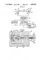
- FIG. 3illustrates another modified electrohydraulic/hydromechanical control construction.
- hydromechanical valve 56acomprises a spool 110 having spaced lands captured for axial sliding motion within a housing, preferably pump housing 76.
- a passage 112provides primary fluid inlet to valve 56a, and a passage 114 provides fluid outlet to pump control piston 16, with passage of fluid from inlet 112 to outlet 114 being past the spool land 116 and thus controlled by position of spool 110 within housing 76.
- Outlet passage 114is also connected past land 116 to drain passage 118 and thence to sump 20.
- the control port 120 of valve 56aprovides access to the pump output at pressure Po onto spool 110 against the opposing force of a coil spring 122 which engages spool 110 within the housing cavity 124.
- Spool 110thus controls application of pump output pressure at inlet 112 to piston 16 through passage 114, and/or from passage 114 to sump 20 through passage 118, as a function of pump outlet pressure Po as on one end of spool 110 compared with pressure of spring 122 on the opposing spool end.
- land 116affords additional communication between passages 112,114, and thus exerts pressure on yoke 18 through piston 16 to de-stroke yoke 18 in the direction 104.
- Electrohydraulic valve 50a in the embodiment of FIG. 3comprises a piston 126 positioned within a housing, preferably pump housing 76, for sliding motion coaxially with spool 110. Piston 126 and housing 76 form a first cavity 128 adjacent to spool 110 and a second cavity 130 on a side of piston 126 remote from spool 110. A finger 132 extends from piston 126 coaxially therewith into control passage 120 of hydromechanical valve 56a for abutment with spool 110 against the force of spring 122. A passage 134 in housing 76 feeds fluid at pump outlet pressure Po to cavity 130. A second passage 136 feeds fluid at pump outlet pressure Po through a damping orifice 138 to cavity 128.
- Cavity 128also communicates through a passage 140 and a valve 142 with sump 20.
- Valve 142is configured normally to block passage of fluid under control of valve spring 142a, and to selectively connect cavity 128 to sump 20 when control computer 34 (FIG. 1) energizes valve coil 142b.
- Valve 142may comprise a proportional valve or a pulse width modulated solenoid valve.
- position of spool 110 within hydromechanical valve 56ais controlled not only directly by pump outlet pressure at port 120 as previously described, but also by abutment force of piston 126 through finger 132. That is, pump outlet pressure Po within cavity 130 is normally balanced on piston 126 by pressure within cavity 128 through orifice 138. However, selective energization of valve 142 effectively bleeds fluid pressure from cavity 128, so that pressure within cavity 130 exceeds that in cavity 128 and piston 126 is urged by the pressure differential thereacross against spool 110. As the combined pressure on spool 110 increases, due to pump outlet pressure Po acting directly on spool 110 and through piston 126, increased fluid is fed past land 116 into passage 114 so as to de-stroke the pump in the direction 104.
- Piston 126has an area several times that of spool 110, so that only a small differential pressure across piston 126 overcomes the force of spring 122. As current to valve 142 is reduced, pressure within cavity 128 increases and force applied to spool 110 by piston 126 correspondingly decreases. Pump stroke is thus stabilized or increased. It will be noted that hydromechanical valve 56a and spool 110 are at all times free to respond to increased pump output pressure independently of electrohydraulic valve 50a. Thus, in the event of electrical failure, piston 126 becomes hydrostatically balanced and pump operation continues under control of hydromechanical valve 56a. It will also be noted that the embodiment of the invention illustrated in FIG. 3 replaces the usual two-stage hydromechanical pressure compensator and electrohydraulic valve with a single assembly. A single-stage electronic valve 142 is used in place of the more expensive two-stage valve 50 in the embodiments of FIGS. 1 and 2.
- aliasingis an error created by mismatch between the sampling frequency of the digital electronics and the frequency of the sampled signal.
- This problemis particularly acute, for example, in closed loop control in which pump output pressure Po is sensed because of a ripple in pump pressure related to pump speed and other factors. Aliasing error will occur if the sampling frequency of the computer is less than twice the frequency of the sampled signal.
- it is undesirable to employ a high sampling frequencybecause this would require inordinate microprocessor time which could otherwise be employed for control purposes.
- anti-aliasing filter 40includes a lowpass filter 150 between pressure sensor 22, for example, and the sample-and-hold input 152 of microcomputer 34.
- Lowpass filter 150in a presently preferred embodiment of the invention comprises a binomial second order filter having the filter characteristic 1/(1+sT) 2 , where s is the conventional Laplace operator and T is the filter time constant and T is usually four times the sampling period of the microprocessor 42.
- Microcomputer logic 42thus operates upon a sampled pump pressure condition signal P L (k) in which the effect of ripple has been substantially removed.
- filter 40also includes a highpass filter 154 which receives the pressure signal Po(t) from sensor 22.
- Highpass filter 154 in the preferred embodiment of the inventionlikewise comprises a binomial second order filter having frequency characteristics which are complementary to those of lowpass filter 150--i.e., having a frequency response given by the expression sT(2+ sT)/(1+sT) 2 in FIG. 4.
- the high frequency output P H (t) of filter 154bypasses the logic unit 42 of microcomputer 34 and is fed to a summing junction 156 at which the high frequency pressure sensor signal components are added to the low frequency components on which control operations have been performed.
- FIGS. 5A and 5Billustrate the analog highpass filter 154 and lowpass filter 150 respectively, together with corresponding frequency characteristics.
- Tis equal to 10 ms and provides satisfactory results.
- Aliasingis likewise a problem with sensor 28 (FIGS. 1 and 6) which is responsive to angle of pump yoke 18 for providing a corresponding pump displacement signal D to the control electronics.
- Temperature stabilityis also a problem in many conventional pump displacement sensor constructions.
- displacement sensor 28comprises a conventional resolver which is mechanically coupled to yoke 18.
- Resolver 28receives a periodic electrical input signal, as from a counter 162 of microcomputer 34 in FIG. 1, and provides corresponding sine and cosine output signals at 90° phase angle and at relative amplitudes which vary as a function of position of yoke 18.
- the frequency f of the periodic input to resolver 28is automatically varied as a function of pump speed N.
- the output of counter 162 at frequency fis switched by the logic unit 142 of microcomputer 34 in FIG. 1 between frequencies f1 and f2 as a preselected function of pump speed N.
- Logic unit 142may include a lookup table in which resolver excitation frequency is stored as a function of pump speed.
- FIG. 7illustrates a pump torque sensor 170 in accordance with a presently preferred embodiment of the invention as comprising a pair of pump speed sensors 26,26a spaced from each other lengthwise of the pump input shaft 14 (which is shown apart from the pump housing).
- Each sensor 26,26acomprises a section 172 of ferromagnetic material and an electromagnetic pickup 174 positioned so as to be responsive to passage of the associated material section 172 to generate a corresponding pulse.
- the outputs N2 and N1 from speed sensors 26,26athus comprise pulsed periodic signals having identical frequencies corresponding to the speed of rotation of shaft 14.
- the variation in the phase relationship between the periodic outputs N2,N1 due to torque or twist on shaft 14is employed to indicate pump input torque.
- the outputs N2,N1are fed through conditioning circuitry 176 responsive to the leading edges of the respective trained pulses, for example, and to a logic network 178 for indicating phase relationship therebetween as a function of the separation in time between the respective pulsed signals--i.e., t(N1)-t(N2).
- the output of network 178, together with a signal indicative of shaft speed--e.g., signal N1--is fed to circuitry such as a lookup table 180 having prestored therein data relating input torque Tq to phase relationship t(N1)-t(N2) as differing predetermined functions of pump speed N.
- Input torque Tq so obtainedis employed to determine input power W as a function of the product Tq*N*k, where k is a constant.
- the signals Tq and W so obtainedmay be used during normal operation, for example, for implementing a constant-torque control mode of operation at pump 12, for measuring and periodically storing pump torque and input power in memory 42 (FIG. 1) for later diagnosis, and during a diagnostic mode of operation to measure rejected power by dividing input power W by pump yoke angle (indicated at displacement D) multiplied by pump speed N and a differential and pressure Po-Pi between pump output and input.
- FIG. 8illustrates a presently preferred embodiment of flow sensor 24 as comprising a sensor body 182 having an inlet port 184, an outlet port 186 and an internal cylindrical cavity 188.
- a spool 190is slidably captured in a passage 192 which extends from cavity 188 and intersects ports 184,186, such that communication between ports 184,186 varies as a function of position of spool 190 within passage 192.
- a piston 194is carried by spool 190 within cavity 188, and a coil spring 196 is captured within cavity 188 and engages piston 194 so as to urge spool 190 toward closure of passage between inlet 184 and outlet 186.
- a fluid passage 198couples outlet 186 to cavity 188 on a side of piston 194 so as to urge spool 190 to the flow-closing position, and a passage 200 couples inlet 184 to cavity 188 on the opposing side of piston 194.
- a slug or bead 204 of ferromagnetic materialis carried on a finger 206 which projects from spool 190 within an extension 208 from body 182.
- a pair of coils 210surrounds extension 208 such that coil inductance varies with position of bead 204 within extension 208.
- the combination of coils 210 and bead 204thus comprise an LVDT having an output Q coupled to analog signal conditioning circuitry 38 in FIG. 1.
- the effect of sensor 24 on pump 12remains constant because of virtually constant pressure drop across the sensor. Furthermore, flow measurement is invariant with fluid viscosity and temperature changes.
Landscapes
- Engineering & Computer Science (AREA)
- Computer Hardware Design (AREA)
- Mechanical Engineering (AREA)
- General Engineering & Computer Science (AREA)
- Fluid-Pressure Circuits (AREA)
Abstract
Description
Claims (20)
Priority Applications (3)
| Application Number | Priority Date | Filing Date | Title |
|---|---|---|---|
| US07/043,829US4823552A (en) | 1987-04-29 | 1987-04-29 | Failsafe electrohydraulic control system for variable displacement pump |
| US07/308,054US4934143A (en) | 1987-04-29 | 1989-02-09 | Electrohydraulic fluid control system for variable displacement pump |
| US07/481,624US5046397A (en) | 1987-04-29 | 1990-02-20 | Electrohydraulic and hydromechanical valve system for dual-piston stroke controller |
Applications Claiming Priority (1)
| Application Number | Priority Date | Filing Date | Title |
|---|---|---|---|
| US07/043,829US4823552A (en) | 1987-04-29 | 1987-04-29 | Failsafe electrohydraulic control system for variable displacement pump |
Related Child Applications (1)
| Application Number | Title | Priority Date | Filing Date |
|---|---|---|---|
| US07/308,054DivisionUS4934143A (en) | 1987-04-29 | 1989-02-09 | Electrohydraulic fluid control system for variable displacement pump |
Publications (1)
| Publication Number | Publication Date |
|---|---|
| US4823552Atrue US4823552A (en) | 1989-04-25 |
Family
ID=21929111
Family Applications (1)
| Application Number | Title | Priority Date | Filing Date |
|---|---|---|---|
| US07/043,829Expired - LifetimeUS4823552A (en) | 1987-04-29 | 1987-04-29 | Failsafe electrohydraulic control system for variable displacement pump |
Country Status (1)
| Country | Link |
|---|---|
| US (1) | US4823552A (en) |
Cited By (59)
| Publication number | Priority date | Publication date | Assignee | Title |
|---|---|---|---|---|
| EP0419835A1 (en)* | 1989-09-25 | 1991-04-03 | Orsco Incorporated | Lubrication monitoring system |
| US5017094A (en)* | 1990-03-12 | 1991-05-21 | Eaton Corporation | Solenoid valve control system for hydrostatic transmission |
| US5073091A (en)* | 1989-09-25 | 1991-12-17 | Vickers, Incorporated | Power transmission |
| US5077975A (en)* | 1989-05-05 | 1992-01-07 | Mannesmann Rexroth Gmbh | Control for a load-dependently operating variable displacement pump |
| US5108267A (en)* | 1991-06-17 | 1992-04-28 | Eaton Corporation | Dual-mode control for hydrostatic transmission |
| EP0495654A1 (en)* | 1991-01-17 | 1992-07-22 | Halliburton Company | Control apparatus for variable displacement pump |
| US5146746A (en)* | 1989-11-20 | 1992-09-15 | Kabushiki Kaisha Toyoda Jidoshokki Seisakusho | Loading/unloading control apparatus for industrial vehicles |
| US5159812A (en)* | 1989-12-29 | 1992-11-03 | Mannesmann Rexroth Gmbh | Circuitry for controlling control coils of servo devices in a hydraulic system |
| US5177964A (en)* | 1989-01-27 | 1993-01-12 | Hitachi Construction Machinery Co., Ltd. | Hydraulic drive traveling system |
| EP0532299A1 (en)* | 1991-09-12 | 1993-03-17 | Vickers Systems Limited | System controls |
| US5267441A (en)* | 1992-01-13 | 1993-12-07 | Caterpillar Inc. | Method and apparatus for limiting the power output of a hydraulic system |
| US5307288A (en)* | 1991-06-07 | 1994-04-26 | Haines Lawrence A | Unitary fluid flow production and control system |
| US5305604A (en)* | 1991-05-10 | 1994-04-26 | Techco Corporation | Control valve for bootstrap hydraulic systems |
| US5515829A (en)* | 1994-05-20 | 1996-05-14 | Caterpillar Inc. | Variable-displacement actuating fluid pump for a HEUI fuel system |
| US5520248A (en)* | 1995-01-04 | 1996-05-28 | Lockhead Idaho Technologies Company | Method and apparatus for determining the hydraulic conductivity of earthen material |
| US5560825A (en)* | 1994-06-21 | 1996-10-01 | Caterpillar Inc. | Edge filter for a high pressure hydraulic system |
| US5628188A (en)* | 1993-03-15 | 1997-05-13 | Mannesmann Rexroth Gmbh | Torque control of hydrostatic machines via the pivot angle or the eccentricity of said machines |
| EP0780522A1 (en)* | 1995-12-22 | 1997-06-25 | Hitachi Construction Machinery Co., Ltd. | Pump Torque control system |
| WO1998025515A1 (en)* | 1996-12-30 | 1998-06-18 | Moorhead William D | Device and method for noninvasive measurement of internal pressure within body cavities |
| US5772403A (en)* | 1996-03-27 | 1998-06-30 | Butterworth Jetting Systems, Inc. | Programmable pump monitoring and shutdown system |
| US5832954A (en)* | 1994-06-21 | 1998-11-10 | Caterpillar Inc. | Check valve assembly for inhibiting Helmholtz resonance |
| US5839279A (en)* | 1996-06-12 | 1998-11-24 | Shin Caterpillar Mitsubishi Ltd. | Hydraulic actuator operation controller |
| US6010309A (en)* | 1997-01-31 | 2000-01-04 | Komatsu Ltd. | Control device for variable capacity pump |
| US6044857A (en)* | 1997-02-13 | 2000-04-04 | Erie Manufacturing Company | Electronic controller for a modulating valve |
| US6073442A (en)* | 1998-04-23 | 2000-06-13 | Caterpillar Inc. | Apparatus and method for controlling a variable displacement pump |
| US6102001A (en)* | 1998-12-04 | 2000-08-15 | Woodward Governor Company | Variable displacement pump fuel metering system and electrohydraulic servo-valve for controlling the same |
| US6244831B1 (en)* | 1998-08-12 | 2001-06-12 | Kawasaki Jukogyo Kabushiki Kaisha | Control device for variable displacement pump |
| EP1106741A4 (en)* | 1998-12-04 | 2002-06-12 | Caterpillar Mitsubishi Ltd | Construction machine |
| US20030220608A1 (en)* | 2002-05-24 | 2003-11-27 | Bruce Huitt | Method and apparatus for controlling medical fluid pressure |
| US20030220607A1 (en)* | 2002-05-24 | 2003-11-27 | Don Busby | Peritoneal dialysis apparatus |
| US20050175442A1 (en)* | 2004-02-11 | 2005-08-11 | George Kadlicko | Housing for rotary hydraulic machines |
| US20050204912A1 (en)* | 2004-03-18 | 2005-09-22 | Kobelco Construction Machinery Co., Ltd. | Hydraulic control system for working machine |
| US7107837B2 (en) | 2002-01-22 | 2006-09-19 | Baxter International Inc. | Capacitance fluid volume measurement |
| US7153286B2 (en) | 2002-05-24 | 2006-12-26 | Baxter International Inc. | Automated dialysis system |
| US20070005030A1 (en)* | 2005-06-21 | 2007-01-04 | Hopkins Mark A | Aspiration control via flow or impedance |
| US20070028608A1 (en)* | 2004-02-11 | 2007-02-08 | George Kadlicko | Rotary hydraulic machine and controls |
| US20070049898A1 (en)* | 2005-06-21 | 2007-03-01 | Hopkins Mark A | Surgical cassette with multi area fluid chamber |
| US20080033346A1 (en)* | 2002-12-31 | 2008-02-07 | Baxter International Inc. | Pumping systems for cassette-based dialysis |
| US20090053072A1 (en)* | 2007-08-21 | 2009-02-26 | Justin Borgstadt | Integrated "One Pump" Control of Pumping Equipment |
| US20090198174A1 (en)* | 2000-02-10 | 2009-08-06 | Baxter International Inc. | System for monitoring and controlling peritoneal dialysis |
| US20090281484A1 (en)* | 2003-10-28 | 2009-11-12 | Baxter International Inc. | Peritoneal dialysis machine |
| US20100150745A1 (en)* | 2008-09-17 | 2010-06-17 | Leif Moberg | Yoke position sensor for a hydraulic device |
| US20110017310A1 (en)* | 2007-07-02 | 2011-01-27 | Parker Hannifin Ab | Fluid valve arrangement |
| US20110088383A1 (en)* | 2007-10-23 | 2011-04-21 | Airbus Operations (S.A.S) | Hydraulic system for aircraft |
| US20110166752A1 (en)* | 2010-01-05 | 2011-07-07 | Dix Peter J | Method for estimating and controlling driveline torque in a continuously variable hydro-mechanical transmission |
| US20110318195A1 (en)* | 2008-12-29 | 2011-12-29 | Alfa Laval Corporate Ab | Pump arrangement with two pump units, system, use and method |
| WO2012007114A3 (en)* | 2010-07-14 | 2012-03-22 | Robert Bosch Gmbh | Hydraulic assembly |
| US8465467B2 (en) | 2006-09-14 | 2013-06-18 | Novartis Ag | Method of controlling an irrigation/aspiration system |
| US8992462B2 (en) | 2002-07-19 | 2015-03-31 | Baxter International Inc. | Systems and methods for performing peritoneal dialysis |
| CN104564630A (en)* | 2013-10-14 | 2015-04-29 | 广州天沅橡胶制品有限公司 | Digital intelligent color paste pump |
| US20160327038A1 (en)* | 2015-05-08 | 2016-11-10 | Danfoss Power Solutions Gmbh & Co. Ohg | Fluid working systems |
| US9514283B2 (en) | 2008-07-09 | 2016-12-06 | Baxter International Inc. | Dialysis system having inventory management including online dextrose mixing |
| US9582645B2 (en) | 2008-07-09 | 2017-02-28 | Baxter International Inc. | Networked dialysis system |
| US9675744B2 (en) | 2002-05-24 | 2017-06-13 | Baxter International Inc. | Method of operating a disposable pumping unit |
| US9675745B2 (en) | 2003-11-05 | 2017-06-13 | Baxter International Inc. | Dialysis systems including therapy prescription entries |
| CN111173808A (en)* | 2018-11-13 | 2020-05-19 | 罗伯特·博世有限公司 | Hydraulic machine, control assembly, hydraulic system and method |
| US11179516B2 (en) | 2017-06-22 | 2021-11-23 | Baxter International Inc. | Systems and methods for incorporating patient pressure into medical fluid delivery |
| US20230028279A1 (en)* | 2021-07-26 | 2023-01-26 | Johnson & Johnson Surgical Vision, Inc. | Progressive cavity pump cartridge with infrared temperature sensors on fluid inlet and outlet |
| US20230265866A1 (en)* | 2020-04-17 | 2023-08-24 | Oshkosh Corporation | Refuse vehicle control systems and methods |
Citations (28)
| Publication number | Priority date | Publication date | Assignee | Title |
|---|---|---|---|---|
| US2889780A (en)* | 1953-03-09 | 1959-06-09 | Gen Electric | Fluid flow measurement and control apparatus |
| US2999482A (en)* | 1957-04-15 | 1961-09-12 | North American Aviation Inc | Digital fluid control system |
| JPS4431052Y1 (en)* | 1967-11-02 | 1969-12-22 | ||
| US3545265A (en)* | 1969-01-27 | 1970-12-08 | Terry E Mcilraith | Horsepower measuring apparatus |
| US4199942A (en)* | 1978-09-28 | 1980-04-29 | Eaton Corporation | Load sensing control for hydraulic system |
| US4293284A (en)* | 1979-10-09 | 1981-10-06 | Double A Products Company | Power limiting control apparatus for pressure-flow compensated variable displacement pump assemblies |
| US4297899A (en)* | 1979-11-23 | 1981-11-03 | Zemco, Inc. | Fluid flow sensor |
| JPS5748204A (en)* | 1980-09-05 | 1982-03-19 | Toshiba Corp | Superconductive electromagnet |
| US4335867A (en)* | 1977-10-06 | 1982-06-22 | Bihlmaier John A | Pneumatic-hydraulic actuator system |
| US4347748A (en)* | 1979-03-27 | 1982-09-07 | Queen's University At Kingston | Torque transducer |
| US4401009A (en)* | 1972-11-08 | 1983-08-30 | Control Concepts, Inc. | Closed center programmed valve system with load sense |
| US4432703A (en)* | 1980-11-26 | 1984-02-21 | Bso Steuerungstechnik Gmbh Industriestrasse | Adjusting arrangement for a hydraulic pump with variable discharge flow quantity |
| US4459860A (en)* | 1981-12-09 | 1984-07-17 | Sperry Limited | Flow sensor with extended low flow range |
| US4496289A (en)* | 1982-03-08 | 1985-01-29 | Robert Bosch Gmbh | Device for controlling and/or measuring operational parameters of an axial piston machine |
| US4502109A (en)* | 1982-09-14 | 1985-02-26 | Vickers, Incorporated | Apparatus for estimating plural system variables based upon a single measured system variable and a mathematical system model |
| US4510750A (en)* | 1980-06-04 | 1985-04-16 | Hitachi Construction Machinery Co., Ltd. | Circuit pressure control system for hydrostatic power transmission |
| US4520681A (en)* | 1984-03-19 | 1985-06-04 | Jeff D. Moore | Apparatus for measuring torque on a rotating shaft |
| US4520674A (en)* | 1983-11-14 | 1985-06-04 | Technology For Energy Corporation | Vibration monitoring device |
| US4525068A (en)* | 1982-09-17 | 1985-06-25 | General Electric Company | Torque measurement method and apparatus |
| US4561250A (en)* | 1981-02-10 | 1985-12-31 | Hitachi Construction Machinery Co., Ltd. | Hydraulic drive system having a plurality of prime movers |
| US4586330A (en)* | 1981-07-24 | 1986-05-06 | Hitachi Construction Machinery Co., Ltd. | Control system for hydraulic circuit apparatus |
| US4590806A (en)* | 1984-10-03 | 1986-05-27 | Simmonds Precision Products, Inc. | Monopole digital vernier torque meter |
| US4602515A (en)* | 1984-12-03 | 1986-07-29 | Simmonds Precision Products, Inc. | Torque measurement apparatus containing embedded data structure and related method |
| US4651045A (en)* | 1985-04-26 | 1987-03-17 | Messerschmitt-Bolkow-Blohm Gmbh | Electromagnetically interference-proof flight control device |
| US4655689A (en)* | 1985-09-20 | 1987-04-07 | General Signal Corporation | Electronic control system for a variable displacement pump |
| US4683746A (en)* | 1985-02-02 | 1987-08-04 | Lucas Electrical Electronics And Systems Limited | Torque monitoring |
| US4685063A (en)* | 1984-07-05 | 1987-08-04 | Siemens Aktiengesellschaft | Process and device for compensation of the effect of roll eccentricities |
| US4714005A (en)* | 1986-07-28 | 1987-12-22 | Vickers, Incorporated | Power transmission |
- 1987
- 1987-04-29USUS07/043,829patent/US4823552A/ennot_activeExpired - Lifetime
Patent Citations (29)
| Publication number | Priority date | Publication date | Assignee | Title |
|---|---|---|---|---|
| US2889780A (en)* | 1953-03-09 | 1959-06-09 | Gen Electric | Fluid flow measurement and control apparatus |
| US2999482A (en)* | 1957-04-15 | 1961-09-12 | North American Aviation Inc | Digital fluid control system |
| JPS4431052Y1 (en)* | 1967-11-02 | 1969-12-22 | ||
| US3545265A (en)* | 1969-01-27 | 1970-12-08 | Terry E Mcilraith | Horsepower measuring apparatus |
| US4401009A (en)* | 1972-11-08 | 1983-08-30 | Control Concepts, Inc. | Closed center programmed valve system with load sense |
| US4335867A (en)* | 1977-10-06 | 1982-06-22 | Bihlmaier John A | Pneumatic-hydraulic actuator system |
| US4199942A (en)* | 1978-09-28 | 1980-04-29 | Eaton Corporation | Load sensing control for hydraulic system |
| US4347748A (en)* | 1979-03-27 | 1982-09-07 | Queen's University At Kingston | Torque transducer |
| US4293284A (en)* | 1979-10-09 | 1981-10-06 | Double A Products Company | Power limiting control apparatus for pressure-flow compensated variable displacement pump assemblies |
| US4297899A (en)* | 1979-11-23 | 1981-11-03 | Zemco, Inc. | Fluid flow sensor |
| US4510750A (en)* | 1980-06-04 | 1985-04-16 | Hitachi Construction Machinery Co., Ltd. | Circuit pressure control system for hydrostatic power transmission |
| JPS5748204A (en)* | 1980-09-05 | 1982-03-19 | Toshiba Corp | Superconductive electromagnet |
| US4432703A (en)* | 1980-11-26 | 1984-02-21 | Bso Steuerungstechnik Gmbh Industriestrasse | Adjusting arrangement for a hydraulic pump with variable discharge flow quantity |
| US4561250A (en)* | 1981-02-10 | 1985-12-31 | Hitachi Construction Machinery Co., Ltd. | Hydraulic drive system having a plurality of prime movers |
| US4586330A (en)* | 1981-07-24 | 1986-05-06 | Hitachi Construction Machinery Co., Ltd. | Control system for hydraulic circuit apparatus |
| US4459860A (en)* | 1981-12-09 | 1984-07-17 | Sperry Limited | Flow sensor with extended low flow range |
| US4496289A (en)* | 1982-03-08 | 1985-01-29 | Robert Bosch Gmbh | Device for controlling and/or measuring operational parameters of an axial piston machine |
| US4581699A (en)* | 1982-09-14 | 1986-04-08 | Vickers, Incorporated | Power transmission |
| US4502109A (en)* | 1982-09-14 | 1985-02-26 | Vickers, Incorporated | Apparatus for estimating plural system variables based upon a single measured system variable and a mathematical system model |
| US4525068A (en)* | 1982-09-17 | 1985-06-25 | General Electric Company | Torque measurement method and apparatus |
| US4520674A (en)* | 1983-11-14 | 1985-06-04 | Technology For Energy Corporation | Vibration monitoring device |
| US4520681A (en)* | 1984-03-19 | 1985-06-04 | Jeff D. Moore | Apparatus for measuring torque on a rotating shaft |
| US4685063A (en)* | 1984-07-05 | 1987-08-04 | Siemens Aktiengesellschaft | Process and device for compensation of the effect of roll eccentricities |
| US4590806A (en)* | 1984-10-03 | 1986-05-27 | Simmonds Precision Products, Inc. | Monopole digital vernier torque meter |
| US4602515A (en)* | 1984-12-03 | 1986-07-29 | Simmonds Precision Products, Inc. | Torque measurement apparatus containing embedded data structure and related method |
| US4683746A (en)* | 1985-02-02 | 1987-08-04 | Lucas Electrical Electronics And Systems Limited | Torque monitoring |
| US4651045A (en)* | 1985-04-26 | 1987-03-17 | Messerschmitt-Bolkow-Blohm Gmbh | Electromagnetically interference-proof flight control device |
| US4655689A (en)* | 1985-09-20 | 1987-04-07 | General Signal Corporation | Electronic control system for a variable displacement pump |
| US4714005A (en)* | 1986-07-28 | 1987-12-22 | Vickers, Incorporated | Power transmission |
Non-Patent Citations (1)
| Title |
|---|
| Yeaple, F. Fluid Power Design Handbook, New York, New York: Marcel Dekker, Inc. (1984), p. 124.* |
Cited By (131)
| Publication number | Priority date | Publication date | Assignee | Title |
|---|---|---|---|---|
| US5177964A (en)* | 1989-01-27 | 1993-01-12 | Hitachi Construction Machinery Co., Ltd. | Hydraulic drive traveling system |
| US5077975A (en)* | 1989-05-05 | 1992-01-07 | Mannesmann Rexroth Gmbh | Control for a load-dependently operating variable displacement pump |
| EP0419835A1 (en)* | 1989-09-25 | 1991-04-03 | Orsco Incorporated | Lubrication monitoring system |
| US5073091A (en)* | 1989-09-25 | 1991-12-17 | Vickers, Incorporated | Power transmission |
| EP0419984A3 (en)* | 1989-09-25 | 1992-03-04 | Vickers, Incorporated | Electrohydraulic control of a hydraulic machine |
| US5146746A (en)* | 1989-11-20 | 1992-09-15 | Kabushiki Kaisha Toyoda Jidoshokki Seisakusho | Loading/unloading control apparatus for industrial vehicles |
| US5159812A (en)* | 1989-12-29 | 1992-11-03 | Mannesmann Rexroth Gmbh | Circuitry for controlling control coils of servo devices in a hydraulic system |
| US5017094A (en)* | 1990-03-12 | 1991-05-21 | Eaton Corporation | Solenoid valve control system for hydrostatic transmission |
| EP0495654A1 (en)* | 1991-01-17 | 1992-07-22 | Halliburton Company | Control apparatus for variable displacement pump |
| US5305604A (en)* | 1991-05-10 | 1994-04-26 | Techco Corporation | Control valve for bootstrap hydraulic systems |
| US5307288A (en)* | 1991-06-07 | 1994-04-26 | Haines Lawrence A | Unitary fluid flow production and control system |
| US5108267A (en)* | 1991-06-17 | 1992-04-28 | Eaton Corporation | Dual-mode control for hydrostatic transmission |
| EP0532299A1 (en)* | 1991-09-12 | 1993-03-17 | Vickers Systems Limited | System controls |
| US5267441A (en)* | 1992-01-13 | 1993-12-07 | Caterpillar Inc. | Method and apparatus for limiting the power output of a hydraulic system |
| US5628188A (en)* | 1993-03-15 | 1997-05-13 | Mannesmann Rexroth Gmbh | Torque control of hydrostatic machines via the pivot angle or the eccentricity of said machines |
| US5515829A (en)* | 1994-05-20 | 1996-05-14 | Caterpillar Inc. | Variable-displacement actuating fluid pump for a HEUI fuel system |
| US5832954A (en)* | 1994-06-21 | 1998-11-10 | Caterpillar Inc. | Check valve assembly for inhibiting Helmholtz resonance |
| US5560825A (en)* | 1994-06-21 | 1996-10-01 | Caterpillar Inc. | Edge filter for a high pressure hydraulic system |
| US5520248A (en)* | 1995-01-04 | 1996-05-28 | Lockhead Idaho Technologies Company | Method and apparatus for determining the hydraulic conductivity of earthen material |
| EP0780522A1 (en)* | 1995-12-22 | 1997-06-25 | Hitachi Construction Machinery Co., Ltd. | Pump Torque control system |
| US5772403A (en)* | 1996-03-27 | 1998-06-30 | Butterworth Jetting Systems, Inc. | Programmable pump monitoring and shutdown system |
| US5839279A (en)* | 1996-06-12 | 1998-11-24 | Shin Caterpillar Mitsubishi Ltd. | Hydraulic actuator operation controller |
| WO1998025515A1 (en)* | 1996-12-30 | 1998-06-18 | Moorhead William D | Device and method for noninvasive measurement of internal pressure within body cavities |
| US5865764A (en)* | 1996-12-30 | 1999-02-02 | Armoor Opthalmics, Inc. | Device and method for noninvasive measurement of internal pressure within body cavities |
| US6010309A (en)* | 1997-01-31 | 2000-01-04 | Komatsu Ltd. | Control device for variable capacity pump |
| US6044857A (en)* | 1997-02-13 | 2000-04-04 | Erie Manufacturing Company | Electronic controller for a modulating valve |
| US6073442A (en)* | 1998-04-23 | 2000-06-13 | Caterpillar Inc. | Apparatus and method for controlling a variable displacement pump |
| US6244831B1 (en)* | 1998-08-12 | 2001-06-12 | Kawasaki Jukogyo Kabushiki Kaisha | Control device for variable displacement pump |
| US6102001A (en)* | 1998-12-04 | 2000-08-15 | Woodward Governor Company | Variable displacement pump fuel metering system and electrohydraulic servo-valve for controlling the same |
| EP1106741A4 (en)* | 1998-12-04 | 2002-06-12 | Caterpillar Mitsubishi Ltd | Construction machine |
| US10322224B2 (en) | 2000-02-10 | 2019-06-18 | Baxter International Inc. | Apparatus and method for monitoring and controlling a peritoneal dialysis therapy |
| US9474842B2 (en) | 2000-02-10 | 2016-10-25 | Baxter International Inc. | Method and apparatus for monitoring and controlling peritoneal dialysis therapy |
| US8323231B2 (en) | 2000-02-10 | 2012-12-04 | Baxter International, Inc. | Method and apparatus for monitoring and controlling peritoneal dialysis therapy |
| US8206339B2 (en) | 2000-02-10 | 2012-06-26 | Baxter International Inc. | System for monitoring and controlling peritoneal dialysis |
| US8172789B2 (en) | 2000-02-10 | 2012-05-08 | Baxter International Inc. | Peritoneal dialysis system having cassette-based-pressure-controlled pumping |
| US20110028892A1 (en)* | 2000-02-10 | 2011-02-03 | Baxter International Inc. | Peritoneal dialysis system having cassette-based-pressure-controlled pumping |
| US20090198174A1 (en)* | 2000-02-10 | 2009-08-06 | Baxter International Inc. | System for monitoring and controlling peritoneal dialysis |
| US7107837B2 (en) | 2002-01-22 | 2006-09-19 | Baxter International Inc. | Capacitance fluid volume measurement |
| US7815595B2 (en) | 2002-05-24 | 2010-10-19 | Baxter International Inc. | Automated dialysis pumping system |
| US20040010223A1 (en)* | 2002-05-24 | 2004-01-15 | Don Busby | Fail safe system for operating medical fluid valves |
| US20060113249A1 (en)* | 2002-05-24 | 2006-06-01 | Robert Childers | Medical fluid machine with air purging pump |
| US7087036B2 (en) | 2002-05-24 | 2006-08-08 | Baxter International Inc. | Fail safe system for operating medical fluid valves |
| US8684971B2 (en) | 2002-05-24 | 2014-04-01 | Baxter International Inc. | Automated dialysis system using piston and negative pressure |
| US7153286B2 (en) | 2002-05-24 | 2006-12-26 | Baxter International Inc. | Automated dialysis system |
| US8529496B2 (en) | 2002-05-24 | 2013-09-10 | Baxter International Inc. | Peritoneal dialysis machine touch screen user interface |
| US10751457B2 (en) | 2002-05-24 | 2020-08-25 | Baxter International Inc. | Systems with disposable pumping unit |
| US8506522B2 (en) | 2002-05-24 | 2013-08-13 | Baxter International Inc. | Peritoneal dialysis machine touch screen user interface |
| US8403880B2 (en) | 2002-05-24 | 2013-03-26 | Baxter International Inc. | Peritoneal dialysis machine with variable voltage input control scheme |
| US20070149913A1 (en)* | 2002-05-24 | 2007-06-28 | Don Busby | Automated dialysis pumping system |
| US20070213651A1 (en)* | 2002-05-24 | 2007-09-13 | Don Busby | Automated dialysis pumping system using stepper motor |
| US8376999B2 (en) | 2002-05-24 | 2013-02-19 | Baxter International Inc. | Automated dialysis system including touch screen controlled mechanically and pneumatically actuated pumping |
| US20030220607A1 (en)* | 2002-05-24 | 2003-11-27 | Don Busby | Peritoneal dialysis apparatus |
| US20030220609A1 (en)* | 2002-05-24 | 2003-11-27 | Robert Childers | Medical fluid pump |
| US20030217962A1 (en)* | 2002-05-24 | 2003-11-27 | Robert Childers | Medical fluid pump |
| US20030220608A1 (en)* | 2002-05-24 | 2003-11-27 | Bruce Huitt | Method and apparatus for controlling medical fluid pressure |
| US7500962B2 (en) | 2002-05-24 | 2009-03-10 | Baxter International Inc. | Medical fluid machine with air purging pump |
| US10137235B2 (en) | 2002-05-24 | 2018-11-27 | Baxter International Inc. | Automated peritoneal dialysis system using stepper motor |
| US9504778B2 (en) | 2002-05-24 | 2016-11-29 | Baxter International Inc. | Dialysis machine with electrical insulation for variable voltage input |
| US6939111B2 (en) | 2002-05-24 | 2005-09-06 | Baxter International Inc. | Method and apparatus for controlling medical fluid pressure |
| US9511180B2 (en) | 2002-05-24 | 2016-12-06 | Baxter International Inc. | Stepper motor driven peritoneal dialysis machine |
| US8075526B2 (en) | 2002-05-24 | 2011-12-13 | Baxter International Inc. | Automated dialysis system including a piston and vacuum source |
| US6953323B2 (en) | 2002-05-24 | 2005-10-11 | Baxter International Inc. | Medical fluid pump |
| US9775939B2 (en) | 2002-05-24 | 2017-10-03 | Baxter International Inc. | Peritoneal dialysis systems and methods having graphical user interface |
| US7789849B2 (en) | 2002-05-24 | 2010-09-07 | Baxter International Inc. | Automated dialysis pumping system using stepper motor |
| US8066671B2 (en) | 2002-05-24 | 2011-11-29 | Baxter International Inc. | Automated dialysis system including a piston and stepper motor |
| US9744283B2 (en) | 2002-05-24 | 2017-08-29 | Baxter International Inc. | Automated dialysis system using piston and negative pressure |
| US6814547B2 (en) | 2002-05-24 | 2004-11-09 | Baxter International Inc. | Medical fluid pump |
| US20110040244A1 (en)* | 2002-05-24 | 2011-02-17 | Baxter International Inc. | Automated dialysis system including a piston and stepper motor |
| US9675744B2 (en) | 2002-05-24 | 2017-06-13 | Baxter International Inc. | Method of operating a disposable pumping unit |
| US20110144569A1 (en)* | 2002-05-24 | 2011-06-16 | Baxter International Inc. | Peritoneal dialysis machine touch screen user interface |
| US11020519B2 (en) | 2002-07-19 | 2021-06-01 | Baxter International Inc. | Systems and methods for performing peritoneal dialysis |
| US9795729B2 (en) | 2002-07-19 | 2017-10-24 | Baxter International Inc. | Pumping systems for cassette-based dialysis |
| US8992462B2 (en) | 2002-07-19 | 2015-03-31 | Baxter International Inc. | Systems and methods for performing peritoneal dialysis |
| US8740836B2 (en) | 2002-07-19 | 2014-06-03 | Baxter International Inc. | Pumping systems for cassette-based dialysis |
| US8740837B2 (en) | 2002-07-19 | 2014-06-03 | Baxter International Inc. | Pumping systems for cassette-based dialysis |
| US8679054B2 (en) | 2002-07-19 | 2014-03-25 | Baxter International Inc. | Pumping systems for cassette-based dialysis |
| US20110106003A1 (en)* | 2002-07-19 | 2011-05-05 | Baxter International Inc. | Dialysis system and method for cassette-based pumping and valving |
| US10525184B2 (en) | 2002-07-19 | 2020-01-07 | Baxter International Inc. | Dialysis system and method for pumping and valving according to flow schedule |
| US9283312B2 (en) | 2002-07-19 | 2016-03-15 | Baxter International Inc. | Dialysis system and method for cassette-based pumping and valving |
| US20080033346A1 (en)* | 2002-12-31 | 2008-02-07 | Baxter International Inc. | Pumping systems for cassette-based dialysis |
| US8206338B2 (en) | 2002-12-31 | 2012-06-26 | Baxter International Inc. | Pumping systems for cassette-based dialysis |
| US8070709B2 (en) | 2003-10-28 | 2011-12-06 | Baxter International Inc. | Peritoneal dialysis machine |
| US8900174B2 (en) | 2003-10-28 | 2014-12-02 | Baxter International Inc. | Peritoneal dialysis machine |
| US10117986B2 (en) | 2003-10-28 | 2018-11-06 | Baxter International Inc. | Peritoneal dialysis machine |
| US20090281484A1 (en)* | 2003-10-28 | 2009-11-12 | Baxter International Inc. | Peritoneal dialysis machine |
| US9675745B2 (en) | 2003-11-05 | 2017-06-13 | Baxter International Inc. | Dialysis systems including therapy prescription entries |
| US9115770B2 (en) | 2004-02-11 | 2015-08-25 | Concentric Rockford Inc. | Rotary hydraulic machine and controls |
| US7992484B2 (en) | 2004-02-11 | 2011-08-09 | Haldex Hydraulics Corporation | Rotary hydraulic machine and controls |
| US20070028608A1 (en)* | 2004-02-11 | 2007-02-08 | George Kadlicko | Rotary hydraulic machine and controls |
| US7380490B2 (en) | 2004-02-11 | 2008-06-03 | Haldex Hydraulics Corporation | Housing for rotary hydraulic machines |
| US20050175442A1 (en)* | 2004-02-11 | 2005-08-11 | George Kadlicko | Housing for rotary hydraulic machines |
| US7284371B2 (en)* | 2004-03-18 | 2007-10-23 | Kobelco Construction Machinery Co., Ltd. | Hydraulic control system for working machine |
| US20050204912A1 (en)* | 2004-03-18 | 2005-09-22 | Kobelco Construction Machinery Co., Ltd. | Hydraulic control system for working machine |
| US20080017022A1 (en)* | 2004-03-18 | 2008-01-24 | Kobelco Construction Machinery Co., Ltd. | Hydraulic control system for working machine |
| US20100030168A1 (en)* | 2005-06-21 | 2010-02-04 | Hopkins Mark A | Aspiration control via flow or impedance |
| US8246580B2 (en) | 2005-06-21 | 2012-08-21 | Novartis Ag | Aspiration control via flow or impedance |
| US20070005030A1 (en)* | 2005-06-21 | 2007-01-04 | Hopkins Mark A | Aspiration control via flow or impedance |
| US20070005029A1 (en)* | 2005-06-21 | 2007-01-04 | Hopkins Mark A | Aspiration control |
| US20070049898A1 (en)* | 2005-06-21 | 2007-03-01 | Hopkins Mark A | Surgical cassette with multi area fluid chamber |
| US7524299B2 (en) | 2005-06-21 | 2009-04-28 | Alcon, Inc. | Aspiration control |
| US7594901B2 (en) | 2005-06-21 | 2009-09-29 | Alcon, Inc. | Surgical cassette with multi area fluid chamber |
| US8465467B2 (en) | 2006-09-14 | 2013-06-18 | Novartis Ag | Method of controlling an irrigation/aspiration system |
| US20110017310A1 (en)* | 2007-07-02 | 2011-01-27 | Parker Hannifin Ab | Fluid valve arrangement |
| WO2009024769A3 (en)* | 2007-08-21 | 2009-04-09 | Halliburton Energy Serv Inc | Integrated 'one pump' control of pumping equipment |
| US20090053072A1 (en)* | 2007-08-21 | 2009-02-26 | Justin Borgstadt | Integrated "One Pump" Control of Pumping Equipment |
| US20110088383A1 (en)* | 2007-10-23 | 2011-04-21 | Airbus Operations (S.A.S) | Hydraulic system for aircraft |
| US8800277B2 (en)* | 2007-10-23 | 2014-08-12 | Airbus Operations Sas | Hydraulic system for aircraft |
| US10561780B2 (en) | 2008-07-09 | 2020-02-18 | Baxter International Inc. | Dialysis system having inventory management including online dextrose mixing |
| US9582645B2 (en) | 2008-07-09 | 2017-02-28 | Baxter International Inc. | Networked dialysis system |
| US9514283B2 (en) | 2008-07-09 | 2016-12-06 | Baxter International Inc. | Dialysis system having inventory management including online dextrose mixing |
| US9690905B2 (en) | 2008-07-09 | 2017-06-27 | Baxter International Inc. | Dialysis treatment prescription system and method |
| US9697334B2 (en) | 2008-07-09 | 2017-07-04 | Baxter International Inc. | Dialysis system having approved therapy prescriptions presented for selection |
| US20100150745A1 (en)* | 2008-09-17 | 2010-06-17 | Leif Moberg | Yoke position sensor for a hydraulic device |
| US8950314B2 (en)* | 2008-09-17 | 2015-02-10 | Parker Hannifin Ab | Yoke position sensor for a hydraulic device |
| US9458843B2 (en)* | 2008-12-29 | 2016-10-04 | Alfa Laval Corporate Ab | Pump arrangement with two pump units, system, use and method |
| US20110318195A1 (en)* | 2008-12-29 | 2011-12-29 | Alfa Laval Corporate Ab | Pump arrangement with two pump units, system, use and method |
| US20110166752A1 (en)* | 2010-01-05 | 2011-07-07 | Dix Peter J | Method for estimating and controlling driveline torque in a continuously variable hydro-mechanical transmission |
| US9097342B2 (en) | 2010-01-05 | 2015-08-04 | Cnh Industrial America Llc | Method for estimating and controlling driveline torque in a continuously variable hydro-mechanical transmission |
| CN102971532A (en)* | 2010-07-14 | 2013-03-13 | 罗伯特·博世有限公司 | Hydraulic unit |
| WO2012007114A3 (en)* | 2010-07-14 | 2012-03-22 | Robert Bosch Gmbh | Hydraulic assembly |
| CN104564630B (en)* | 2013-10-14 | 2016-08-10 | 广州天沅橡胶制品有限公司 | Digital intelligent color paste pump |
| CN104564630A (en)* | 2013-10-14 | 2015-04-29 | 广州天沅橡胶制品有限公司 | Digital intelligent color paste pump |
| US11655816B2 (en)* | 2015-05-08 | 2023-05-23 | Danfoss Power Solutions Gmbh & Co. Ohg | Fluid working systems |
| US11499552B2 (en) | 2015-05-08 | 2022-11-15 | Danfoss Power Solutions Gmbh & Co. Ohg | Fluid working systems |
| US20160327038A1 (en)* | 2015-05-08 | 2016-11-10 | Danfoss Power Solutions Gmbh & Co. Ohg | Fluid working systems |
| US11179516B2 (en) | 2017-06-22 | 2021-11-23 | Baxter International Inc. | Systems and methods for incorporating patient pressure into medical fluid delivery |
| CN111173808A (en)* | 2018-11-13 | 2020-05-19 | 罗伯特·博世有限公司 | Hydraulic machine, control assembly, hydraulic system and method |
| US20230265866A1 (en)* | 2020-04-17 | 2023-08-24 | Oshkosh Corporation | Refuse vehicle control systems and methods |
| US12044254B2 (en)* | 2020-04-17 | 2024-07-23 | Oshkosh Corporation | Refuse vehicle control systems and methods |
| US20230028279A1 (en)* | 2021-07-26 | 2023-01-26 | Johnson & Johnson Surgical Vision, Inc. | Progressive cavity pump cartridge with infrared temperature sensors on fluid inlet and outlet |
| US12338816B2 (en)* | 2021-07-26 | 2025-06-24 | Johnson & Johnson Surgical Vision, Inc. | Progressive cavity pump cartridge with infrared temperature sensors on fluid inlet and outlet |
Similar Documents
| Publication | Publication Date | Title |
|---|---|---|
| US4823552A (en) | Failsafe electrohydraulic control system for variable displacement pump | |
| US4934143A (en) | Electrohydraulic fluid control system for variable displacement pump | |
| US6382226B1 (en) | Method for detecting broken valve stem | |
| DE602004012500T2 (en) | Method for the diagnosis of a cyclic system | |
| DE69019204T2 (en) | Electronic braking system. | |
| DE69427487T2 (en) | ACTUATOR OF A VALVE WITH PRESSURE FEEDBACK, DYNAMIC CORRECTION AND DIAGNOSTICS | |
| EP0017537B1 (en) | Electrohydraulic doser actuator | |
| DE3587150T2 (en) | DRIVE POSITION SYNTHESIS FROM A CONTROL SYSTEM FOR FAULT DETECTION. | |
| US4987737A (en) | Fuel control system for gas turbine aeroengine overspeed protection | |
| US5724878A (en) | Hydraulic operating mechanism for a convertible top | |
| US5046397A (en) | Electrohydraulic and hydromechanical valve system for dual-piston stroke controller | |
| DE10355250A1 (en) | Method for determining leaks of a pressure fluid in a pressure actuated machine using a mathematical equation relating pressure and flow volume and comparing actual values to a reference value | |
| JPS60157501A (en) | Electricity-liquid pressure apparatus of reciprocal liquid pressure motor | |
| US3774641A (en) | Electrohydraulic control arrangement for hydraulic actuators | |
| US4612489A (en) | Power transmission | |
| WO2007134568A1 (en) | Modular fuel supply device for a gas turbine | |
| CN1063938A (en) | Valve diagnostic system with auxiliary transducer box | |
| US3626283A (en) | Apparatus for monitoring and indicating an operational failure of a linear voltage differential transformer | |
| US4904999A (en) | Fault monitoring system for aircraft power control units | |
| US3724330A (en) | Self monitoring control system utilizing an electrical model for each control means | |
| US6065494A (en) | Hydraulic function-performing unit | |
| US2722198A (en) | Combined fluid pressure and electrically controlled servomotor system | |
| US2969773A (en) | Hydraulic valve-controlled servo device | |
| WO1994010457A1 (en) | Pressure control valve for a hydraulic actuator | |
| US3543642A (en) | Unitized control module for a hydraulic actuation apparatus |
Legal Events
| Date | Code | Title | Description |
|---|---|---|---|
| AS | Assignment | Owner name:VICKERS, INCORPORATED, TROY, OAKLAND, MI A CORP. O Free format text:ASSIGNMENT OF ASSIGNORS INTEREST.;ASSIGNORS:EZELL, LARRY O.;SCHMID, JOHN;TOVEY, PETER;REEL/FRAME:004720/0618 Effective date:19870413 | |
| FEPP | Fee payment procedure | Free format text:PAYOR NUMBER ASSIGNED (ORIGINAL EVENT CODE: ASPN); ENTITY STATUS OF PATENT OWNER: LARGE ENTITY | |
| STCF | Information on status: patent grant | Free format text:PATENTED CASE | |
| FEPP | Fee payment procedure | Free format text:PAYER NUMBER DE-ASSIGNED (ORIGINAL EVENT CODE: RMPN); ENTITY STATUS OF PATENT OWNER: LARGE ENTITY Free format text:PAYOR NUMBER ASSIGNED (ORIGINAL EVENT CODE: ASPN); ENTITY STATUS OF PATENT OWNER: LARGE ENTITY | |
| FEPP | Fee payment procedure | Free format text:PAYER NUMBER DE-ASSIGNED (ORIGINAL EVENT CODE: RMPN); ENTITY STATUS OF PATENT OWNER: LARGE ENTITY Free format text:PAYOR NUMBER ASSIGNED (ORIGINAL EVENT CODE: ASPN); ENTITY STATUS OF PATENT OWNER: LARGE ENTITY | |
| FEPP | Fee payment procedure | Free format text:PAYER NUMBER DE-ASSIGNED (ORIGINAL EVENT CODE: RMPN); ENTITY STATUS OF PATENT OWNER: LARGE ENTITY Free format text:PAYOR NUMBER ASSIGNED (ORIGINAL EVENT CODE: ASPN); ENTITY STATUS OF PATENT OWNER: LARGE ENTITY | |
| FPAY | Fee payment | Year of fee payment:4 | |
| FPAY | Fee payment | Year of fee payment:8 | |
| FPAY | Fee payment | Year of fee payment:12 |