US4823290A - Method and apparatus for monitoring the operating environment of a computer system - Google Patents
Method and apparatus for monitoring the operating environment of a computer systemDownload PDFInfo
- Publication number
- US4823290A US4823290AUS07/076,235US7623587AUS4823290AUS 4823290 AUS4823290 AUS 4823290AUS 7623587 AUS7623587 AUS 7623587AUS 4823290 AUS4823290 AUS 4823290A
- Authority
- US
- United States
- Prior art keywords
- computer system
- sensor
- accordance
- alarm
- signals
- Prior art date
- Legal status (The legal status is an assumption and is not a legal conclusion. Google has not performed a legal analysis and makes no representation as to the accuracy of the status listed.)
- Expired - Fee Related
Links
Images


Classifications
- G—PHYSICS
- G06—COMPUTING OR CALCULATING; COUNTING
- G06F—ELECTRIC DIGITAL DATA PROCESSING
- G06F11/00—Error detection; Error correction; Monitoring
- G06F11/30—Monitoring
- G06F11/3058—Monitoring arrangements for monitoring environmental properties or parameters of the computing system or of the computing system component, e.g. monitoring of power, currents, temperature, humidity, position, vibrations
- G—PHYSICS
- G06—COMPUTING OR CALCULATING; COUNTING
- G06F—ELECTRIC DIGITAL DATA PROCESSING
- G06F11/00—Error detection; Error correction; Monitoring
- G06F11/07—Responding to the occurrence of a fault, e.g. fault tolerance
- G06F11/0703—Error or fault processing not based on redundancy, i.e. by taking additional measures to deal with the error or fault not making use of redundancy in operation, in hardware, or in data representation
- G06F11/0751—Error or fault detection not based on redundancy
- G06F11/0754—Error or fault detection not based on redundancy by exceeding limits
- G06F11/0757—Error or fault detection not based on redundancy by exceeding limits by exceeding a time limit, i.e. time-out, e.g. watchdogs
- G—PHYSICS
- G06—COMPUTING OR CALCULATING; COUNTING
- G06F—ELECTRIC DIGITAL DATA PROCESSING
- G06F11/00—Error detection; Error correction; Monitoring
- G06F11/07—Responding to the occurrence of a fault, e.g. fault tolerance
- G06F11/0703—Error or fault processing not based on redundancy, i.e. by taking additional measures to deal with the error or fault not making use of redundancy in operation, in hardware, or in data representation
- G06F11/0751—Error or fault detection not based on redundancy
- G06F11/0754—Error or fault detection not based on redundancy by exceeding limits
- G06F11/076—Error or fault detection not based on redundancy by exceeding limits by exceeding a count or rate limit, e.g. word- or bit count limit
- G—PHYSICS
- G06—COMPUTING OR CALCULATING; COUNTING
- G06F—ELECTRIC DIGITAL DATA PROCESSING
- G06F11/00—Error detection; Error correction; Monitoring
- G06F11/22—Detection or location of defective computer hardware by testing during standby operation or during idle time, e.g. start-up testing
- G06F11/2294—Detection or location of defective computer hardware by testing during standby operation or during idle time, e.g. start-up testing by remote test
- G—PHYSICS
- G06—COMPUTING OR CALCULATING; COUNTING
- G06F—ELECTRIC DIGITAL DATA PROCESSING
- G06F11/00—Error detection; Error correction; Monitoring
- G06F11/30—Monitoring
- G06F11/32—Monitoring with visual or acoustical indication of the functioning of the machine
- G06F11/324—Display of status information
- G06F11/327—Alarm or error message display
- G—PHYSICS
- G06—COMPUTING OR CALCULATING; COUNTING
- G06F—ELECTRIC DIGITAL DATA PROCESSING
- G06F11/00—Error detection; Error correction; Monitoring
- G06F11/30—Monitoring
- G06F11/32—Monitoring with visual or acoustical indication of the functioning of the machine
- G06F11/324—Display of status information
- G06F11/328—Computer systems status display
- G—PHYSICS
- G06—COMPUTING OR CALCULATING; COUNTING
- G06F—ELECTRIC DIGITAL DATA PROCESSING
- G06F11/00—Error detection; Error correction; Monitoring
- G06F11/30—Monitoring
- G06F11/34—Recording or statistical evaluation of computer activity, e.g. of down time, of input/output operation ; Recording or statistical evaluation of user activity, e.g. usability assessment
- G06F11/3466—Performance evaluation by tracing or monitoring
- G06F11/3476—Data logging
Definitions
- This inventionrelates to computer system protection, and more particularly to equipment functioning with a computer system for monitoring the environment in which the computer system operates to provide early warning of environmental conditions that can damage components of the computer system.
- thermometeronly reads the temperature at the spot at which it is mounted, and local "hot spots" inside of particular equipment cabinets are not detected before failure of the equipment inside cabinets.
- excessive temperatures inside a cabinet caused by a "hot spot”cause a particular piece of equipment to operate as to introduce errors in the data output from the equipment, and from other equipment in the computer room that cooperate therewith.
- Such computational problems and equipment failures caused by excessive temperaturesare costly in terms of failed equipment that must be repaired or replaced, in terms of unreliable data output from the computer system, and in terms of computer system "down time". Accordingly, there is a need in the art for a computer system environment monitoring arrangement that can monitor different computer system environmental operating conditions at many points around and inside component parts of the computer system without constant human interaction. Such a monitoring arrangement should provide an output identifying what and where a potentially dangerous environmental operating conditions exist. This permits correction of problems before there is failure of equipment exposed to the excessive environmental operating condition, and minimizes errors caused by equipment subject to improper environmental operating conditions.
- a computer system environmental monitoring arrangementthat can store data received from the outputs of a variety of sensors around and in a computer system. The stored data can be used to determine if rates of change of different environmental conditions are dangerous and need immediate attention.
- the stored data from the sensorscan be used to create histograms showing trends in the operating environment of the computer room and in individual pieces of equipment therein.
- the present inventionis a computer environment monitoring system that cooperates with a host computer so that the host computer controls monitoring and analysis.
- This novel monitoring systemutilizes a plurality of sensors of different types, such as air flow and temperature sensors, located in many places around a computer room, such as in equipment cabinets and in air plenums.
- the signals output from the sensorsare periodically scanned using a sensor interface device and the data from the sensors is stored by the host computer system.
- a predetermined levelas determined by the host computer while running an analysis program
- an alarmis given to make the computer system operating personnel aware of the condition while identifying the location and type of problem at the main console of the computer system.
- rates of change of environmental conditions sensed by the sensorsexceed predetermined rates, an alarm is given. Alarms from unattended computer installation sites are forwarded to attended locations using an autodialer.
- the host computer systemstores the data received from the sensors of the computer environment monitoring system and can then use the data to develop a histogram for each sensor showing change trends in the environment monitored by each sensor. These histograms can be analyzed and show potential problems before they become actual problems. In this manner corrective actions may be taken before potential problems turn into real problems. Sensor history data stored by the host computer system at unattended computer installation sites may be retrieved for analysis over a telephone line and modem connected to the unattended computer system. In addition, these histograms may be used to identify faulty computer installation designs so that installation design changes may be made before any problems occur.
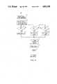
- FIG. 1shows a block diagram schematic of the apparatus functioning with a host computer for monitoring the operating environment of a computer system
- FIG. 2is a pictorial representation showing part of a computer room and where environment monitoring and other types of sensors may be located therein;
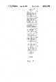
- FIG. 3is a table showing the contents of a portion of a working table in which is stored information regarding the associated sensor
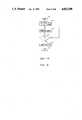
- FIG. 4is a flow chart showing the steps in the operation of a scanning program used to obtain and store the digitized outputs from sensors;
- FIG. 5is a flow chart showing the steps in analyzing stored data to determine if any sensor measurements indicate a situation for which alarms are to be energized.
- FIG. 6is a flow chart showing the steps in an alarm reset program
- FIG. 7is a flow chart showing the steps in generating a histogram of the readings from a sensor.
- FIG. 8is a flow chart showing the steps in operating a failsafe timer.
- FIG. 1a detailed block diagram of the novel apparatus for monitoring the environment in which a computer system operates.
- the apparatuscomprises a sensor interface device (SID) 10 which is preferably a commercially available SID2000 available from the Microswitch Division of Honeywell, Inc. in Freeport, Illinois.
- SIDsensor interface device
- a plurality of sensors 11 through 14are used to provide inputs to SID 10 regarding environmental and other conditions in which a host computer system 17 operates.
- Sensors 11-14are exemplary only and a wide variety of sensors may be utilized.
- the sensorsmay monitor environmental conditions such as temperature, humidity, air flow, liquid level and airborne particulate matter.
- other types of sensorsmay monitor other conditions such as door openings and DC and AC power supply voltage levels. All these types of sensors are well known in the art and are not described in detail herein. When more sensors are used than can be handled by a single SID 10, more SID 10 devices may be added.
- exemplary analog output sensors 11 and 12are connected to inputs of input analog module 15, and exemplary direct contact output sensors 13 and 14 are connected to inputs of input direct current module 16. Signals outputs from analog sensors 11 and 12 are in analog form and must be converted to digital form before being input to processor 18 within sensor interface device 10.
- Input analog module 15has a plurality of analog-to-digital converters and converts the analog signals input to it from analog sensors 11 and 12 into the required digital format.
- Sensors 11 and 12are exemplary only and a number of types of analog sensors may be connected to the inputs of module 15. Examples of the types of analog sensors that provide analog output signals are listed in the last paragraph. However, in the prior art, sensors measuring a given environmental condition may be found that provide binary signal outputs rather than analog signal outputs. Binary signal output sensors have their outputs connected to an input direct current module.
- the temperature sensorsmay be Model TD2A sensors available from the Microswitch Division of Honeywell, Inc. These temperature sensors are nothing more than variable resistors and the outputs of the temperature sensors are not applied directly to an input analog module 15.
- a transmitter box(not shown), Model X82825 available from Microswitch Division is used. The transmitter box converts the resistance output from a temperature sensor to a voltage which can then be digitized by module 15.
- Another analog output sensoris a humidity sensor which is a Model HMW20U sensor available from Vaisala Corp. in Woburn, Massachusetts. Still another type of analog output sensor is an air flow indicator.
- Input analog module 15is a Model SID-IAN-10-5 also available from the Microswitch Division of Honeywell, Inc.
- the liquid level sensor that is used in the preferred embodiment of the inventionis a Model D901 liquid detector available from Honeywell, Inc. in Newhouse, Scotland.
- the liquid level sensoris a zero to five volts direct current sensor so is connected to an input of input direct current module 16.
- An open door sensoris also a direct current sensor and is also connected to an input of direct current module 16.
- Open door sensorsare widely available from many sources and provide an open or a closed contact when a door is opened. Module 16 responds to an open contact to output one binary number, and responds to a closed contact to output a second binary number to module 16.
- Direct current module 16is a Model SID-IDC module available from the Microswitch Division of Honeywell, Inc.
- Buffer module 29is a Model SID-BUF Buffer Module available from the Microswitch Division of Honeywell, Inc.
- the stored program in memory 19is also responsive to trouble indication signals received from host computer 27 to enable alarm functions.
- An output module 20is responsive to alarm enable signals to activate alarms. More particularly, output module 20 is a direct current module and closes contacts to activate a visual alarm 22, an audible alarm 58, or an auto dialer 23 to send a pre-recorded message to a remote site.
- Output module 20is a Model ORY-H module available from the Microswitch Division of Honeywell, Inc. Auto dialer 23 is configured to periodically place a pre-recorded trouble message call to a remote site until it is disabled from doing so.
- a host computer system 17is served by the environment monitoring equipment described in the previous paragraphs.
- System 17is shown in a very simple form since computer systems are so well known in the art.
- a host processor 27which is accessed via an I/O processor in a manner well known in the art.
- Processor 27has a main memory 25 associated therewith which may be made up of many of the types of memory presently used in computer systems.
- Main memory 25is used to store programs and data used in the normal operation of host processor 27.
- main memory 25is also used to store a number of program and data files for the operation of the environmental monitoring apparatus described herein.
- These data filesinclude a sensor history file that is used to store the digitized sensor signals originally generated by sensors 11 through 14 and sent to host computer system 17 for storage and analysis, a sensor library file, a point table file, and a history file copy.
- the history filecontains many individual records, one per sensor, to store the signals from the particular sensor.
- Interface converter 30is provided to perform a communication format translation function.
- Converter 30is a Model 422-232 converter available from California Networks Controls in Torrance, California.
- Digitized sensor data temporarily stored in buffer module 29has its communication format converted by converter 30, and is output therefrom to a communications processor 24 which operates to pass the digitized sensor data to host computer system 17.
- Processor 24is a Model DataNet 8 communication processor available from Honeywell Inc.
- Digitized sensor data forwarded to host computer system 17 via its I/O processor 26is stored in associated records in a history data file (HIST) and in a working copy table in main memory 25. There is record in the HIST file and working copy table for each sensor.
- a program named SCANalso stored in main memory 25 controls obtaining and storing the digitized data from all active sensors. The SCAN program also handles communications to console 28, and initiating any autodialer, visual and audible alarm enable requests to sensor interface device (SID) 10.
- host processor 17Periodically, responsive to the SCAN program stored in main memory 25, host processor 17 sends requests via circuits 26, 24, 30 and 29 to processor 18 in SID 10. Processor 18 responds to these requests to scan the sensors and send the data in binary form output from modules 15 and 16 to host processor 27. The sensor data is returned over the same communication path to host processor 27 which, under control of the SCAN program, stores the data in the appropriate records of the history data file in main memory 25.
- the time interval for requesting processor 18 to read and forward sensor datamay vary from a short time such as one minute or less to a longer time such as five minutes or more as decided upon by the owner of host computer system 17.
- host processor 27under control of the SCAN program attaches the date and time that the data was received and stores them all in the appropriate records of the history file (HIST) in main memory 25.
- HISThistory file
- the newest five sets of sensor dataare also stored in fields of a working copy table.
- the signals passed back and forth between host computer system 17 and sensor interface device 10is in a particular communication format as defined in the SID2000 specification sheets available from Honeywell - Microswitch Division.
- the communication formathas a first field which contains a leading framing character of two bytes in length.
- the framing characteris two colon symbols (::) when host computer 17 is sending a request to SID 10.
- SID 10is sending data or information to computer system 17 other symbols are used.
- Two pound symbols (##)are used as the leading framing character by SID 10 when responding to a sensor data request from host computer 17.
- Two dollar symbols ($$)are used as the leading framing character when SID 10 is sending an error message to host computer 17, and two percent symbols (%%) are used as the leading framing character when SID 10 is sending other types of messages to computer system 17.
- the second field of the communication formathas two bytes that are for addressing purposes and are used only when there are more than one interface device 10, to identify a particular one of the devices 10. In addition, these two bytes are used only when a request is being sent to a device 10. When there is only one device 10 "01" is placed in this field.
- the third fieldis a command field having two bytes that is used to specify a command from host computer 17 for device 10 to perform. When device 10 transmits to computer 17, the third field has two zeros therein.
- the fourth and fifth fieldseach have two bytes, but these two fields are reserved and are not used at this time.
- the sixth fieldhas two bytes that are used to specify the number of bytes in the following data field.
- the seventh fieldis the data field and has a length as specified by the sixth field.
- the data fieldis used to convey whatever data or other information is necessary to execute the command specified in field three.
- An example of the datais that read from a sensor.
- the eighth fieldis a checksum field of two bytes which is the twos complement of fields 2 through 7.
- the last and ninth fieldis for a trailing framing character to mark the end of the communication format. It is carriage return (C/R) when the transmission is from SID 10 to host computer system 17, and is a question mark (? ) when the transmission is from host computer system 17 to SID 10.
- a sensor library(SLIB) which contains numerous information about each kind of sensor and its alarm limit levels.
- the sensor library filehas one record for each kind of sensor, and the makeup of a record is described further in the specification with reference to FIG. 3.
- PTBLpoint table
- HISThistory file
- the SCAN programAfter the digitized sensor data, and date and time signals for each sensor are received, initially processed and stored in the HIST file and the working copy table, the SCAN program is ended and goes to sleep to be rerun any predetermined time later, which may advantageously be one minute.
- the SCAN programis described in greater detail further in this specification with reference to FIG. 4.
- Host processor 27then runs an ANALYSIS, program to check the stored sensor data.
- PTBLpoint table
- Each of the sensors 11 through 14has a point table as part of its working copy table as previously mentioned. The point table may be modified at any time from console 28 while the environmental monitoring equipment is in operation.
- an alarm signalis immediately sent to processor 18 that causes autodialer 23 to be activated and forward a recorded alarm message to a remote site as previously described. If the computer site is attended an alarm message is first given at CRT 56 of console 28. When the visual alarm message at CRT 56 is not acknowledged before several readings from the sensor are received, the program then causes a visual alarm enable signal to be sent to processor 18 in SID 10.
- the visual alarm enable signalcauses processor 18 to activate a major visual alarm 22, via output module 20 which may be a flashing light on a pillar or wall as represented in FIG. 2.
- an audible alarm enable signalis generated and forwarded to SID processor 18 which causes activation of audible alarm 58 via output module 20.
- This audible alarmis loud enough that it should get the attention of the maintenance personnel who should acknowledge it at console 28.
- the subsequent alarmsare not activated.
- still another alarm enable signalis sent to processor 18 in SID 10 which causes autodialer 23 to be enabled to pass the alarm condition on to a remote location.
- Auto dialer 23is set up so that when it is energized it initiates a telephone call to the remote attended site and plays a pre-recorded message indicating the alarm. Auto dialer 23 will periodically recall the remote site to place the same alarm message call until it is disabled from doing so. To disable autodialer 23, the maintenance person at the remote site who receives the alarm message call dials back to auto dialer interface 54 and, when auto dialer interface 54 answers the call, sends a specific touch tone signal. Auto dialer 23 responds to the touch tone signal via control from autodialer interface 54 to stop repeating the alarm message call. Processor 18 stores an indication of the message acknowledgement and the number of times that the call was repeated until acknowledged.
- Host processor 27periodically interrogates SID processor 18 and retrieves this information which it then stores with a time and date stamp in the appropriate records of the history file, and in the working copy table in main memory 25 for the sensor that caused the alarm. Thereafter, it is up to the maintenance personnel at the remote site to initiate remedial action.
- host processor 27After the periodic collection and storage of each set of sensor data from all sensors via SID 10, host processor 27 under control of the ANALYSIS program first compares the most recently received sensor data, which is stored in the working copy table for each sensor, with the maximum, minimum and rate of change values stored in the previously described point table (PTBL) for the associated sensor. Initially, some of the stored values in each point table are default values, but the owner of the computer system may initially or at a later time set the default values to other values as they wish.
- PTBLpoint table
- a water pipe or the air conditioning system in the room in which computer system is locatedmay become faulty and leak into an underfloor space below the computer system where all cabling and some conditioned air is routed.
- a liquid level sensoris located under the floor and detects the presence of the water. With water present there is a closed switch that causes a first binary digit to be output from input direct current module 16. When no water is detected there is a second binary digit output from direct current module 16. These binary digits are zero and one.
- host processor 27 under control of the ANALYSIS programchecks the most recently stored binary number from each liquid level sensor and detects the first binary number it knows water is present and action is taken. Host processor 27 first displays the alarm message at CRT 56. Subsequent alarm actions caused by non-acknowledgement of the alarm message are described in a previous paragraph.
- the maintenance personnel or system ownercan initiate a request causing a histogram program to read out the stored sensor data in the sensor records in the history file for all or specified ones of the sensors and create histograms showing how the data is changing over a specified period of time for the specified sensors.
- the histogramis displayed on CRT 21 or other video terminals (not shown) that are connected to host computer system 17, and the histogram may also be routed to a printer 55 at the console for a hard copy printout.
- maintenance personnel at a remote sitemay place a data call via a telephone line to modem 31, be connected to host processor 27 via communication processor 24 and I/O processor 26, and request that the histogram program be run by processor 27.
- the resulting histogramis then transmitted via modem 31 to the remote site for display thereat.
- the maintenance personneleither local or remote, analyze the histograms to determine the state of the environmental conditions being monitored and can identify potential environmental problems before they actually become problems causing damage and causing computer down time. Remedial action may then be initiated to make changes that will prevent the problems from occurring. This maximizes up time for the computer system and also minimizes lost or damaged data caused by system components that have failed.
- sensorsmay also be used to monitor operating conditions within components of the host computer system. For example, DC voltage levels from power supplies, and AC power supply levels may be monitored to make sure that their outputs stay within defined voltage specifications. In addition, access doors to the computer room and particular pieces of computer equipment may be monitored to detect when they are opened.
- the SLIBis only used initially to write the parameters into the point table (PTBL) of the working copy table associated with each sensor.
- This parameter informationis used by the SCAN and ANALYSIS programs for converting raw digitized data received from a sensor into a value such as degrees Fahrenheit or Celsius.
- HISCduplicate history file
- HISThistory file
- HISThistory file
- working copy tableof which information from the point table file is part and in which are stored in individual fields the current and previous four readings from each sensor. The collection and storage of readings from sensors in the working copy table and the records of the history file are described further in this specification with reference to FIG. 3.
- a file designated TCSLis used to store records of all requests made to the console
- a file designated FCSLis used to store records of all the responses received from the console. This is done because the scanning and storing of sensor data has the highest priority and to protect this priority all communications are handled through the TCSL and FCSL files.
- FIG. 2is shown a pictorial representation of a part of a computer room and representatively shows where environment monitoring and other sensors would be located.
- Large computer systemsare typically installed in special constructed rooms that are generally kept closed, that have their own air conditioning systems to maintain a cool operating environment for the equipment that makes up the computer system, and that filters the air in the room. Cooling is required because the computer equipment generates a lot of heat and, in a closed room, the temperature would rise rapidly to temperatures that will cause equipment failures.
- Many computer roomshave raised floors so that cabling between pieces of equipment be out of sight under the floor.
- the under floor spaceis often used as a pressurized air plenum through which cooled air passes and then is vented next to or inside pieces of computer equipment. To do this, part or all of the cooled air output from the air conditioning system is forced under the raised floor and there are vents through the floor at required points. This is representatively shown in FIG. 2.
- processor 40input/output multiplexer 41
- communication processor 42console 43
- AC power distribution panel 44hard disk memory 45
- magnetic tape drive 46magnetic tape drive 46
- air conditioning unit 47motor/generator set 48.
- SID 2000 apparatus 51used for monitoring the environment of the computer system
- bell alarm 52used for monitoring the environment of the computer system
- visual alarm 59used for monitoring the environment in the computer room.
- air conditioning unit 47takes room air, cools it, and blows it into under floor space 49. There are a number of vents through floor 50 which allow the cooled air to rise up into the computer room at numerous locations such as shown by the arrows by console 43, hard disk unit 45 and tape drive 46.
- processor 40 and I/O multiplexer 41have their own internal air circulation fans that circulate cooled room air through these equipment housings.
- Temperature sensorsare shown in FIG. 2 as circles with a "T” in them and are located to monitor temperature inside the cabinets of processor 40, I/O multiplexer 41, communications processor 42, console 43, AC power distribution panel 44, hard disk unit 45, magnetic tape unit 46, and air conditioning unit 47. Temperature sensors are also placed on a pillar 53 and under floor 50. The temperature sensors monitor the equipment and room temperatures. Humidity sensors are shown as circles with an "H” in them and are located over processor 40, on pillar 53, and monitoring cooled exhaust air from air conditioning unit 47. Humidity is monitored because if the air in the computer room is too dry static electricity problems arise that can damage the computer equipment and otherwise cause the loss of data.
- Air flow sensorsare shown as circles with a "A” in them and are located inside the equipment housings of processor 40 and I/O multiplexer 41 to check that the cooling fans inside of these equipment housings are functioning.
- An air flow sensoris also located inside air conditioning unit to check that the circulation blower therein is functioning.
- AC voltage sensorsare shown as circles with a "V” inside and one is located with AC power distribution panel 44 to monitor for AC power failures.
- DC voltage sensorsare also shown as circles with a "V” inside and one is located with motor-generator set 48, which provides emergency DC power to the computer equipment, to monitor its output voltage level.
- Airborne particle sensorsare shown as a circle with a "P” inside and are mounted on pillar 53 and inside hard disk memory unit 45. Airborne particles in the form of dust are very detrimental to disk drives and cause data drop outs.
- Liquid level sensorsare shown as a circle with an "L” inside and one is located under floor 50 beneath air conditioning unit 47 to monitor for water leaking from this unit.
- the environment monitoring equipment 51 under control of host processor 27first causes a visual alarm 22 and then audible alarm bell 52 to be energized to alert computer system maintenance personnel in the computer room.
- the maintenance personnelcan look at CRT 56 which is a part of console 28, or at CRT 21, to find out what type of sensor and its location that caused the alarm to be generated, and can then investigate the matter and take remedial measures.
- the sensor data stored in each point table recordis shown in FIG. 3 which is described hereinafter.
- the first field in the point tablecontains general identity and location information regarding the associated sensor.
- the second fieldcontains a three digit number which is the channel address of the particular sensor.
- the first digit of the channel addressindicates the particular sensor interface device 10 (SID) that the particular sensor is connected to. This is needed when there are so many sensors that more than one SID 10 is required to scan their outputs.
- the second digit of the channel addressindicates which interface module (i.e. modules 15 and 16 in FIG. 1) the particular sensor is interfaced through.
- the third digit of the channel addressindicates the particular input channel on the particular interface module identified by the second digit. With these three digits in the second field of the channel address the particular sensor identified thereby may be addressed automatically, or manually from console 28.
- the third field of each point tablecontains an entry indicating if the interface module 15 or 16 to which any particular sensor is connected is an intelligent module.
- the fourth field of the point tablecontains information indicating if all sensors connected to the module identified in fields two and three are to be read out.
- the fifth fieldcontains information identifying the particular sensor. This identity is needed to convert raw data received from the sensors. For example, if the particular sensor is a temperature sensor a binary number indicating a voltage is returned from SID 10. Using the sensor identity information in the fifth field the voltage indicated by the binary number can be converted to a temperature.
- the sixth fieldoperates in conjunction with the fifth field and indicates the units of the measurement for the sensor. For the example of the temperature sensor, the sixth field is used to indicate if the measurement is in Fahrenheit or Centigrade degrees.
- the information in the fifth and sixth fieldsis not required for outputs from sensors such as water present and door open sensors, but is required for analog output sensors such as the temperature and humidity sensors.
- the seventh field of each point tablecontains a correction factor which is used to correct the converted reading. It can be understood that this information is needed for readings from analog type sensors, such as a temperature sensor, but is not needed for water present or door open sensors.
- the eighth field of each point tableindicates an offset factor to be applied to each converted sensor reading.
- the ninth fieldindicates an absolute low value for the particular sensor.
- the tenth fieldindicates an absolute high value for the particular sensor. The use of the absolute high and low values in fields nine and ten is described in more detail further in the specification with reference to the CHECK program flow chart in FIG. 5. Briefly, when an alarm is given the rate of change is calculated using the five sets of data in the working copy table associated with the sensor that caused the alarm, and this calculated rate of change is then used to determine the time until the readings from the alarm causing sensor will reach the appropriate one of the absolute values.
- the eleventh fieldis used to indicate a chosen maximum slope or rate of change of the output of the associated sensor beyond which an alarm indication is to be given.
- Host processor 27under the control of the SCAN program uses the five sets of sensor data stored in the working copy table to calculate the recent rate of change of the output from the sensor and stores it for later use by the CHECK program which compares it to the figure stored in field eleven. If the calculated rate of change is greater in either a negative or positive direction than the stored value in field eleven the program selectively enables one of the previously mentioned alarms.
- the twelfth fieldcontains a number that indicates the chosen low level output from the sensor below which an alarm indication is first given at the CRT 56 at console 28.
- the thirteenth fieldsimilarly indicates the chosen high level output from the sensor and above which an alarm indication is first given at the CRT 56 of console 28.
- the CHECK programcompares the most recently received sensor data against the entries in fields twelve and thirteen to determine if an alarm should be given.
- Field fourteenis used to store a noise figure which is added or subtracted from sensor readings stored in the working copy table to dampen swings in readings caused by noise. This has the effect of reducing false alarms caused by noise conditions.
- the fifteenth field of each point tableis a single bit which indicates if the associated sensor is active or is disabled. If a sensor is determined to be defective after causing an erroneous alarm, to prevent subsequent erroneous alarms until the sensor is replaced or otherwise repaired, the sensor is disabled. That is, the output from the sensor is ignored because the entry in field fifteen indicates that the sensor is disabled. Maintenance personnel using a keyboard 57 at console 28 access the point table for the particular sensor and write into this fifteenth field that the sensor is disabled. After the sensor is replaced or otherwise repaired, the entry in field fifteen is changed to indicate that the sensor is again enabled.
- FIG. 4is shown a flow chart showing the steps of the SCAN program in collecting data from the sensors and storing same in the sensor records of the history file and in the working copy table before analysis.
- the program represented by this flow chartis repeatedly being run. Typically, it is run once a minute, and collects data from all sensors. Accordingly, the program cycles once for all sensors and then is placed in a sleep state to be rerun about one minute later.
- the one minute figureis arbitrary and is a default sensor reading period that may readily be changed.
- the parameters in the point tableare the same as the sensor library which has previously been described with reference to FIG. 3. If the answer is no, processing reverts back to block 60 and SID 10 is queried for the output of the next sensor.
- a channelmay be inactivated by the system operator if the sensor is defective as previously described. If the answer to the active channel inquiry is yes, the time and date of the query is added to the sensor data in the working copy table as shown by block 63.
- the digitized sensor datawhich is in raw form, is then converted to an understandable form using the parameter data stored in field seven of the point table portion of the working copy table associated with the sensor. This is represented by block 64 in FIG. 4.
- the data in converted formindicates, for example, a figure in degrees, or air flow in cubic feet per minute.
- the converted datais then stored in the record in the history file for the particular sensor as shown by block 65.
- the newest sensor datais then compared with the previous sensor data to calculate the rate of change of the data, and this calculated rate of change figure is stored in the working table for the sensor. This calculation and storage is represented by block 66.
- the programchecks if the sensor data just received, converted and stored is from the last of the sensors as represented by decision block 67. If the data is not from the last sensor th program cycles back to block 60 to repeat the steps just described for the next sensor. If the data was from the last sensor, sensor data collection is completed and will not be repeated for another minute.
- a checkis made to determine if any acknowledgements of alarm indications have been received. If the answer to this determination is no, the program goes to sleep for one minute, per block 69, and then repeats the steps described above for all sensors. However, if the check determines that an alarm acknowledgement has been received via console 28 or from a remote site via autodialer interface 54, the program branches to another program represented by the flow chart in FIG. 6 to determine which alarm has been acknowledged and then that alarm is reset. The branch is shown as the letter A in a circle in FIG. 4. The program represented by the flow chart in FIG. 6 is described further in this specification.
- FIG. 5is shown the flow chart for the ANALYSIS program that is run after sensor data has been received and stored by the SCAN program.
- the ANALYSIS programchecks the newest data received from the sensors and stored in the working copy table against the maximum, minimum and rate of change parameters stored in the point table to determine if an alarm should be given and, if so, what type of alarm.
- the parametersare selected by the owner of the computer system as previously mentioned.
- the stored parametersinitially have a default value level but may be changed at any time as experience with the computer system indicates is necessary.
- the program represented by the flow chart shown in FIG. 5is run once for the received and stored data for each of the sensors, starting after each new set of data is received from the sensors via SID 10.
- the first stepis to read the newest sensor data for a particular sensor from its work copy record, as shown by block 70.
- the programretrieves the stored maximum sensor value, at and above which an alarm is to be given, copied from the point table file (PTBL) into the sensor working copy table and compares it against the newest sensor data as shown at decision block 71. If the pre-stored maximum sensor level has been exceeded an error message is prepared for display at console 28. This is done at block 72.
- PTBLpoint table file
- the programthen branches to decision block 73 to check if the latest sensor reading is less than the stored minimum sensor level. If the latest sensor reading is lower than the stored minimum sensor level the program branches to block 74 and an appropriate error message is prepared for display at console 28. However, if the latest sensor reading is not lower than the stored, minimum default value, the program branches to block 75 to check the rate of change of the last few sensor readings. To do this, the rate of change calculated at block 66 of the SCAN program is read out and compared with the maximum rate of change stored in the work copy record for the particular sensor.
- the programexits block 76 and comes to a stop at block 114 because the latest sensor reading does not exceed any default values. The program then goes back to block 111 and restarts to analyze the data from the next sensor. However, if the rate of change is greater than the stored default value, the program goes to block 77 and prepares a rate of change error message.
- the programprogresses to block 78 and checks the direction of change of the latest sensor reading with regards to the previous sensor reading and, if there is no direction of change, checks if the sensor reading value is remaining steady.
- the latest readingcan be out of bounds but be the same as the previous sensor reading, less than the previous sensor reading, or greater than the previous sensor reading. Whatever the determination is from block 78, in block 79 a message is prepared indicating the result.
- the programtakes the latest stored sensor reading and the previous readings stored in the working copy table and calculates the change rate in units/time. Thereafter, at block 81, the program prepares a message indicating that rate of change to be displayed at CRT 56.
- the programuses the rate of change previously calculated and, if the maximum or minimum limits haven't been exceeded, calculates the time to reach those limits assuming that the rate of change doesn't vary in subsequent sensor readings. If the maximum or minimum limit has already been exceeded the program calculates what the sensor output would theoretically be in ten minutes if the rate of change doesn't vary in subsequent sensor readings. After either of these calculations is done the program goes to block 83 and prepares a message indicating the information just calculated in block 82.
- a counter located in the working copy table associated with the particular sensoris incremented by one.
- the programthen checks the count in the counter mentioned in the last paragraph.
- the programchecks if the count in the counter is greater than zero. When an alarm condition has been detected for the first time, as described with the sensor reading checks performed in blocks 71, 73 and 76, the count in the counter goes from zero to one.
- the output from decision block 85will be a yes and the program goes to block 86 which causes all previously prepared messages (blocks 72, 74, 77, 79, 81 and 83) to be displayed on CRT 56 of console 28.
- a first alarm conditiononly results in a message being displayed on CRT 56. There are no other visual or audible alarms energized until subsequent times that an alarm condition is detected from the same sensor.
- the next counter checkis made at decision block 87 which checks if the count in the counter is greater than four. The count of four indicates that on subsequent reading and checking of the particular sensor an alarm condition has continued to be detected but not acknowledged. As the counter is being incremented up to four, only the messages to CRT 56 are regenerated each time at block 86. Until the counter reaches the count of five the program exits decision block 87 as a no and the program stops at block 112. However, when a count of five or greater is detected, the program goes to block 88 which causes the visual alarm lights 22 to be energized via SID 10 as previously described. These alarm lights 22 hopefully get the attention of the maintenance personnel who check the CRT at the console to determine what and where the trouble is.
- FIG. 6is shown the flow chart for the program branch shown as an A in a circle in FIG. 3.
- This program branchis used to reset alarms that have been acknowledged via console 28 at host computer system 17.
- the starting point into this program branchis also shown by the letter A in a circle.
- the first stepis to determine which sensor caused the alarm that has been acknowledged from console 28 of the computer system. This is done at block 93. After that determination has been made the program goes to block 94 and retrieves the count in the counter that is part of the working copy table associated with the sensor that caused the alarm that has been acknowledged. In decision block 95 the count in the counter is checked to determine if it is equal to or greater than six. If it greater than six it is known that autodialer 23 had been energized in block 92 of FIG. 5. Accordingly, the program exits to block 96 and resets the autodialer.
- the decision at block 95is a no and the program goes to decision block 97.
- the counter contentsare again checked to see if they are equal to or greater than five. If the count is equal to or greater than five the program knows that the audible alarm had been energized in block 89 of FIG. 5 and, accordingly, goes to block 98 to reset the audible alarm. Similarly, if the count in the counter was not high enough to energize the visual alarm, the count in the counter will be less than five. At this count the output from decision block 97 is a no and the program goes to decision block 99. At decision block 99 the program checks if the count in the counter is equal to or greater than four. If the count is equal to or greater than four the program goes to block 100 to reset the visual alarm. If the count is less than four the program goes to block 101.
- FIG. 7is shown a flow chart for the program HISTOGRAM used to generate histograms using the stored sensor readings in the sensor records in the history file.
- This programstarts at block 116 when requested from console 28, from CRT 21, or remotely via modem 31. It could be changed, however, by one skilled in the art so that it is run periodically.
- personnel at a remote sitecan also call in via a telephone line and modem 31 to read out the records of the history file for selected ones or all of the sensors.
- This program represented by the flow chartwould then be run at the remote site using the sensor data transferred over the telephone line to generate the histograms.
- the operator requesting that histograms be generatedinputs this information via keyboard 57.
- the programsimilarly inquires about the range of time over which the histograms are to cover, and also the time intervals for data readings to be displayed. Again this information is input via keyboard 57. If desired, by specifying time intervals larger than that at which the sensor readings are taken, not all data will be graphed on the histogram. Then, at block 107, the operator is requested to input the type of data that is to be displayed with the histograms. With all this information the program knows all the parameters needed to generate the requested histograms.
- the programuses the parameters input to it in the previous steps to read the appropriate data out of the records in the history file for the first selected sensor.
- the data read out of the history file and the parameters input to the programare used to graph the histogram on an output device.
- output devicessuch as CRT 57 and printer 55 at console 28, but there are many other types that may also be used.
- other linesare also drawn on the histograms. These other lines are the maximum and minimum limit levels and the rate of change limit level.
- a failsafe featureis also provided to check the operation of sensory interface device (SID) 10. If host processor 27 under control of the monitoring and analysis programs is unable to connect to SID 10 to request scanning or other functions, a signal in the form of a trouble message is given to the maintenance personnel via CRT 56 at console 28. To acknowledge receipt of the message the maintenance personnel are instructed to operate a particular key on keyboard 57 of console 28. The generation of the trouble message, the acknowledgement reply by key operation, and a time and date stamp are stored in the appropriate record of the history file for the sensor that caused the alarm. At the same time, SID 10 is monitoring to determine if it is unable to connect to computer system 17.
- SID 10is monitoring to determine if it is unable to connect to computer system 17.
- FIG. 8is shown a flow chart of the steps performed in implementing a failsafe timer in SID 10 processor 18 to monitor the communication path between SID 10 and host computer system 17.
- the program shown in FIG. 8is started at block 118.
- host processor 27sends a command to SID 10 to reset a failsafe counter inmplemented with processor 18 to six-hundred. This is shown at block 119.
- the failsafe counteris decremented by the count of one every second. Thus, if the counter is not reset, it will count down to zero in ten minutes.
- the programchecks to see if the counter has decremented to zero as shown at block 121. If the answer is no, the program returns to block 120 and the failsafe counter is decremented again.
- host processor 27accesses SID 10 it sends a command to processor 18 to reset the counter in the failsafe timer to six-hundred.
- host processor 27Before the expiration of the ten minute count down of the failsafe timer described in the previous paragraphs, host processor 27 will have also detected the failure to communicate. Processor 27 places a message on CRT 56 at console, and on CRT 21 associated with communications processor 24 if the path is intact and processors 24 and 26 are functioning properly. The maintenance personnel can disable the autodialer until the trouble is cleared to stop the trouble message from being transmitted to the remote location.
Landscapes
- Engineering & Computer Science (AREA)
- Theoretical Computer Science (AREA)
- Computing Systems (AREA)
- Quality & Reliability (AREA)
- Physics & Mathematics (AREA)
- General Engineering & Computer Science (AREA)
- General Physics & Mathematics (AREA)
- Alarm Systems (AREA)
- Emergency Alarm Devices (AREA)
Abstract
Description
Claims (24)
Priority Applications (4)
| Application Number | Priority Date | Filing Date | Title |
|---|---|---|---|
| US07/076,235US4823290A (en) | 1987-07-21 | 1987-07-21 | Method and apparatus for monitoring the operating environment of a computer system |
| CA000572682ACA1327399C (en) | 1987-07-21 | 1988-07-21 | Method and apparatus for monitoring the operating environment of a computer system |
| AU20008/88AAU613384B2 (en) | 1987-07-21 | 1988-07-25 | Method and apparatus for monitoring the operating environment of a computer system |
| EP88111955AEP0352340B1 (en) | 1987-07-21 | 1988-07-25 | Method for monitoring the operating environment of a computer system |
Applications Claiming Priority (1)
| Application Number | Priority Date | Filing Date | Title |
|---|---|---|---|
| US07/076,235US4823290A (en) | 1987-07-21 | 1987-07-21 | Method and apparatus for monitoring the operating environment of a computer system |
Publications (1)
| Publication Number | Publication Date |
|---|---|
| US4823290Atrue US4823290A (en) | 1989-04-18 |
Family
ID=22130754
Family Applications (1)
| Application Number | Title | Priority Date | Filing Date |
|---|---|---|---|
| US07/076,235Expired - Fee RelatedUS4823290A (en) | 1987-07-21 | 1987-07-21 | Method and apparatus for monitoring the operating environment of a computer system |
Country Status (4)
| Country | Link |
|---|---|
| US (1) | US4823290A (en) |
| EP (1) | EP0352340B1 (en) |
| AU (1) | AU613384B2 (en) |
| CA (1) | CA1327399C (en) |
Cited By (149)
| Publication number | Priority date | Publication date | Assignee | Title |
|---|---|---|---|---|
| US4901701A (en)* | 1987-11-12 | 1990-02-20 | Injection Research Specialists, Inc. | Two-cycle engine with electronic fuel injection |
| US4937763A (en)* | 1988-09-06 | 1990-06-26 | E I International, Inc. | Method of system state analysis |
| US4967712A (en)* | 1987-11-12 | 1990-11-06 | Injection Research Specialists, Inc. | Two-cycle engine with electronic fuel injection |
| US4988988A (en)* | 1988-10-20 | 1991-01-29 | Nittan Company Ltd. | Central monitoring and alarming system |
| US4999614A (en)* | 1987-11-26 | 1991-03-12 | Fujitsu Limited | Monitoring system using infrared image processing |
| US5068798A (en)* | 1989-03-03 | 1991-11-26 | Precision Systems, Inc. | Process environment monitoring system |
| US5105370A (en)* | 1988-04-14 | 1992-04-14 | Fike Corporation | Environmental detection system useful for fire detection and suppression |
| US5115225A (en)* | 1990-11-13 | 1992-05-19 | Compaq Computer Corporation | Disk drive unit overheating warning system |
| US5128881A (en)* | 1988-09-09 | 1992-07-07 | Saum Enterprises, Inc. | Means and methods for predicting hold time in enclosures equipped with a total flooding fire extinguishing system |
| US5133605A (en)* | 1989-12-11 | 1992-07-28 | Fujitsu Limited | Monitoring system employing infrared image |
| US5216623A (en)* | 1990-06-06 | 1993-06-01 | M. T. Mcbrian, Inc. | System and method for monitoring and analyzing energy characteristics |
| US5216893A (en)* | 1990-10-30 | 1993-06-08 | Whirlpool International B.V. | Device for controlling the operation of a refrigeration appliance, such as a domestic refrigerator, a freezer or the like |
| US5230074A (en)* | 1991-01-25 | 1993-07-20 | International Business Machines Corporation | Battery operated computer power management system |
| US5230055A (en)* | 1991-01-25 | 1993-07-20 | International Business Machines Corporation | Battery operated computer operation suspension in response to environmental sensor inputs |
| US5270945A (en)* | 1989-03-03 | 1993-12-14 | Precision Systems, Inc. | Process environment monitoring system |
| US5287292A (en)* | 1992-10-16 | 1994-02-15 | Picopower Technology, Inc. | Heat regulator for integrated circuits |
| US5325156A (en)* | 1992-11-20 | 1994-06-28 | Xerox Corporation | Service call initiation and feedback interface for a reprographic machine |
| US5337413A (en)* | 1992-02-06 | 1994-08-09 | Tandem Computers Incorporated | Environment monitoring system for standard interface bus computer systems |
| US5347646A (en)* | 1988-09-28 | 1994-09-13 | Hitachi, Ltd. | Remote operation control for computer system |
| US5422806A (en)* | 1994-03-15 | 1995-06-06 | Acc Microelectronics Corporation | Temperature control for a variable frequency CPU |
| US5432932A (en)* | 1992-10-23 | 1995-07-11 | International Business Machines Corporation | System and method for dynamically controlling remote processes from a performance monitor |
| US5463775A (en)* | 1991-06-10 | 1995-10-31 | International Business Machines Corporation | System and method for performing monitoring of resources in a data processing system in real time |
| US5477417A (en)* | 1992-08-28 | 1995-12-19 | Kabushiki Kaisha Toshiba | Electronic equipment having integrated circuit device and temperature sensor |
| US5483468A (en)* | 1992-10-23 | 1996-01-09 | International Business Machines Corporation | System and method for concurrent recording and displaying of system performance data |
| US5485142A (en)* | 1994-04-08 | 1996-01-16 | The United States Of America As Represented By The Administrator Of The National Aeronautics And Space Administration | Remote monitor alarm system |
| US5506955A (en)* | 1992-10-23 | 1996-04-09 | International Business Machines Corporation | System and method for monitoring and optimizing performance in a data processing system |
| US5513359A (en)* | 1993-07-23 | 1996-04-30 | International Business Machines Corporation | Desktop computer having a single-switch suspend/resume function |
| GB2295299A (en)* | 1994-11-16 | 1996-05-22 | Network Services Inc Enterpris | Monitoring computer network transactions |
| US5539396A (en)* | 1992-09-28 | 1996-07-23 | Horiba, Ltd. | Remote monitoring system for instrumentation |
| US5552776A (en)* | 1991-09-23 | 1996-09-03 | Z-Microsystems | Enhanced security system for computing devices |
| US5553235A (en)* | 1992-10-23 | 1996-09-03 | International Business Machines Corporation | System and method for maintaining performance data in a data processing system |
| US5555191A (en)* | 1994-10-12 | 1996-09-10 | Trustees Of Columbia University In The City Of New York | Automated statistical tracker |
| US5701044A (en)* | 1993-08-09 | 1997-12-23 | Siemens Aktiengesellschaft | Process and device for monitoring the temperature of an electric generator |
| US5892690A (en)* | 1997-03-10 | 1999-04-06 | Purechoice, Inc. | Environment monitoring system |
| US5955946A (en)* | 1998-02-06 | 1999-09-21 | Beheshti; Ali | Alarm/facility management unit |
| US6049798A (en)* | 1991-06-10 | 2000-04-11 | International Business Machines Corporation | Real time internal resource monitor for data processing system |
| US6148418A (en)* | 1998-06-22 | 2000-11-14 | Holtek Semiconductor Inc. | Computer environment monitor device |
| US6203191B1 (en) | 1998-10-28 | 2001-03-20 | Speculative Incorporated | Method of junction temperature determination and control utilizing heat flow |
| AU732436B2 (en)* | 1993-07-26 | 2001-04-26 | Lenovo (Singapore) Pte. Ltd. | Desktop computer system having multi-level power management |
| US6281803B1 (en)* | 1999-03-16 | 2001-08-28 | Warren Frederick Davis | Control mat monitoring and warning apparatus and method |
| US6317839B1 (en) | 1999-01-19 | 2001-11-13 | International Business Machines Corporation | Method of and apparatus for controlling supply of power to a peripheral device in a computer system |
| US6369706B1 (en) | 1999-05-10 | 2002-04-09 | Gateway, Inc. | System and method for protecting a digital information appliance from environmental influences |
| US20020055826A1 (en)* | 2000-03-30 | 2002-05-09 | Wegerich Stephan W. | Signal differentiation system using improved non-linear operator |
| US20020087290A1 (en)* | 2000-03-09 | 2002-07-04 | Wegerich Stephan W. | System for extraction of representative data for training of adaptive process monitoring equipment |
| US20020124081A1 (en)* | 2001-01-26 | 2002-09-05 | Netbotz Inc. | Method and system for a set of network appliances which can be connected to provide enhanced collaboration, scalability, and reliability |
| US6453266B1 (en)* | 1999-01-29 | 2002-09-17 | International Business Machines Corporation | Peak detecting shock gauge and damage diagnostic for mobile and handheld computers |
| US20020133320A1 (en)* | 2001-01-19 | 2002-09-19 | Wegerich Stephan W. | Adaptive modeling of changed states in predictive condition monitoring |
| US20020161885A1 (en)* | 1999-10-27 | 2002-10-31 | Netbotz Inc. | Methods for displaying physical network topology and environmental status by location, organization, or responsible party |
| RU2198418C2 (en)* | 2000-10-30 | 2003-02-10 | Таганрогский государственный радиотехнический университет | Method of centralized control over n objects |
| US20030055607A1 (en)* | 2001-06-11 | 2003-03-20 | Wegerich Stephan W. | Residual signal alert generation for condition monitoring using approximated SPRT distribution |
| US6556939B1 (en) | 2000-11-22 | 2003-04-29 | Smartsignal Corporation | Inferential signal generator for instrumented equipment and processes |
| US6577978B1 (en)* | 1998-03-20 | 2003-06-10 | Sensors & Software Inc. | Microprocessor and microcontroller stabilized geophysical instruments |
| US20030139908A1 (en)* | 2001-04-10 | 2003-07-24 | Wegerich Stephan W. | Diagnostic systems and methods for predictive condition monitoring |
| US20030149796A1 (en)* | 2002-01-04 | 2003-08-07 | Emerson Theodore F. | Method and apparatus for creating a secure embedded I/O processor for a remote server management controller |
| US20030208480A1 (en)* | 2002-05-03 | 2003-11-06 | Netbotz, Inc. | Method and apparatus for collecting and displaying network device information |
| US20040054938A1 (en)* | 2002-09-17 | 2004-03-18 | Belady Christian L. | Controlling a computer system based on an environmental condition |
| US6714977B1 (en) | 1999-10-27 | 2004-03-30 | Netbotz, Inc. | Method and system for monitoring computer networks and equipment |
| US6718277B2 (en) | 2002-04-17 | 2004-04-06 | Hewlett-Packard Development Company, L.P. | Atmospheric control within a building |
| US20040078292A1 (en)* | 1996-09-03 | 2004-04-22 | Trevor Blumenau | Content Display Monitoring by a Processing System |
| US6775641B2 (en) | 2000-03-09 | 2004-08-10 | Smartsignal Corporation | Generalized lensing angular similarity operator |
| US6782351B2 (en) | 2001-09-11 | 2004-08-24 | Purechoice, Inc. | Air quality monitoring and space management system coupled to a private communications network |
| US20040201471A1 (en)* | 2003-04-14 | 2004-10-14 | Netbotz, Inc. | Extensible sensor monitoring, alert processing and notification system and method |
| US20040204881A1 (en)* | 2001-01-12 | 2004-10-14 | Ingersoll-Rand Company | Environmental monitoring system |
| WO2004090679A2 (en) | 2003-04-14 | 2004-10-21 | Netbotz, Inc. | Environmental monitoring device |
| US20040236718A1 (en)* | 2003-04-14 | 2004-11-25 | Netbotz, Inc. | Method and system for journaling and accessing sensor and configuration data |
| US20050038914A1 (en)* | 2001-05-17 | 2005-02-17 | Andrew Prendergast | Method of optimising content presented to a user within a communication network |
| US6882963B1 (en)* | 1999-09-23 | 2005-04-19 | Intel Corporation | Computer system monitoring |
| US20050114511A1 (en)* | 1997-03-21 | 2005-05-26 | Owen Davis | Method and apparatus for tracking client interaction with a network resource |
| US20050131652A1 (en)* | 2003-12-03 | 2005-06-16 | Corwin Wallace D. | Remote monitoring system |
| US6912386B1 (en)* | 2001-11-13 | 2005-06-28 | Nokia Corporation | Method for controlling operation of a mobile device by detecting usage situations |
| US20050188047A1 (en)* | 2003-10-27 | 2005-08-25 | Netbotz, Inc. | System and method for network device communication |
| US6957172B2 (en) | 2000-03-09 | 2005-10-18 | Smartsignal Corporation | Complex signal decomposition and modeling |
| US20050251339A1 (en)* | 2004-05-05 | 2005-11-10 | St- Infonox | Methods and systems for monitoring environments |
| US20050286220A1 (en)* | 2004-06-29 | 2005-12-29 | Moore David A | Modular sensor assembly |
| US20060155517A1 (en)* | 2004-12-22 | 2006-07-13 | Hewlett-Packard Development Company, L.P. | Apparatus and system for monitoring environmental factors in a computer system |
| US20060168975A1 (en)* | 2005-01-28 | 2006-08-03 | Hewlett-Packard Development Company, L.P. | Thermal and power management apparatus |
| US20070150215A1 (en)* | 2002-01-02 | 2007-06-28 | American Power Conversion Corporation | Method and apparatus for preventing overloads of power distribution networks |
| US20070185986A1 (en)* | 2003-01-31 | 2007-08-09 | John Griffin | Method and system of measuring and recording user data in a communications network |
| US7302313B2 (en) | 2001-02-07 | 2007-11-27 | Aircuity, Inc. | Air quality monitoring systems and methods |
| US20080006487A1 (en)* | 1997-03-12 | 2008-01-10 | Gannett Satellite Information Network, Inc. | Information Display System |
| US7330886B2 (en) | 1999-10-27 | 2008-02-12 | American Power Conversion Corporation | Network appliance management |
| US20080041076A1 (en)* | 2006-08-15 | 2008-02-21 | American Power Conversion Corporation | Method and apparatus for cooling |
| US7376722B1 (en) | 1999-08-06 | 2008-05-20 | Red Sheriff Limited | Network resource monitoring and measurement system and method |
| US20080142068A1 (en)* | 2006-12-18 | 2008-06-19 | American Power Conversion Corporation | Direct Thermoelectric chiller assembly |
| US20080155441A1 (en)* | 2006-12-22 | 2008-06-26 | Long Bruce T | Method for performing a data center hardware upgrade readiness assessment |
| US20080173089A1 (en)* | 2007-01-19 | 2008-07-24 | Seagate Technology Llc | Transducing system with integrated environmental sensors |
| US7406516B2 (en) | 1997-03-21 | 2008-07-29 | Netratings, Inc. | System and method for monitoring the use of a resource by a client connected to a computer network having one or more servers in communication with one or more clients |
| US20080183425A1 (en)* | 2006-12-15 | 2008-07-31 | Smart Signal Corporation | Robust distance measures for on-line monitoring |
| US20080180908A1 (en)* | 2007-01-23 | 2008-07-31 | Peter Wexler | In-row air containment and cooling system and method |
| US7409310B1 (en) | 2005-01-21 | 2008-08-05 | Z Microsystems, Inc. | System and method for tracking operational data in a distributed environment |
| US20080245083A1 (en)* | 2006-08-15 | 2008-10-09 | American Power Conversion Corporation | Method and apparatus for cooling |
| US20080263150A1 (en)* | 2001-01-26 | 2008-10-23 | American Power Conversion Corporation | Methods for displaying physical network topology and environmental status by location, organization, or responsible party |
| US20080300965A1 (en)* | 2007-05-31 | 2008-12-04 | Peter Campbell Doe | Methods and apparatus to model set-top box data |
| US20090012633A1 (en)* | 2007-07-06 | 2009-01-08 | Microsoft Corporation | Environmental Monitoring in Data Facilities |
| US7539597B2 (en) | 2001-04-10 | 2009-05-26 | Smartsignal Corporation | Diagnostic systems and methods for predictive condition monitoring |
| US20090138313A1 (en)* | 2007-05-15 | 2009-05-28 | American Power Conversion Corporation | Methods and systems for managing facility power and cooling |
| US20100011062A1 (en)* | 2008-07-14 | 2010-01-14 | St-Infonox, Inc. | Automated bioremediation system |
| US20100057263A1 (en)* | 2006-08-15 | 2010-03-04 | Ozan Tutunoglu | Method and apparatus for cooling |
| US7705721B1 (en)* | 2007-03-13 | 2010-04-27 | Network Appliance, Inc. | Apparatus and method for sensing and responding to environmental conditions of a computer system at non-uniform polling intervals |
| US7711814B1 (en) | 2004-12-13 | 2010-05-04 | American Power Conversion Corporation | Method and system for remote monitoring of a power supply device with user registration capability |
| US20100131109A1 (en)* | 2008-11-25 | 2010-05-27 | American Power Conversion Corporation | System and method for assessing and managing data center airflow and energy usage |
| US20100170663A1 (en)* | 2006-12-18 | 2010-07-08 | American Power Conversion Corporation | Modular ice storage for uninterruptible chilled water |
| US20100211810A1 (en)* | 2009-02-13 | 2010-08-19 | American Power Conversion Corporation | Power supply and data center control |
| US20100211669A1 (en)* | 2009-02-13 | 2010-08-19 | American Power Conversion Corporation | Data center control |
| US20100286956A1 (en)* | 2009-05-08 | 2010-11-11 | American Power Conversion Corporation | System and method for predicting cooling performance of arrangements of equipment in a data center |
| US20100287018A1 (en)* | 2009-05-08 | 2010-11-11 | American Power Conversion Corporation | System and method for arranging equipment in a data center |
| US20100286955A1 (en)* | 2009-05-08 | 2010-11-11 | American Power Conversion Corporation | System and method for predicting maximum cooler and rack capacities in a data center |
| EP2263533A1 (en) | 2009-06-18 | 2010-12-22 | Deutsche Telekom AG | Enhancing security and emergency functionalities in mobile phones based on detection of physical shocks |
| US20110077795A1 (en)* | 2009-02-13 | 2011-03-31 | American Power Conversion Corporation | Data center control |
| US20110154270A1 (en)* | 2008-08-29 | 2011-06-23 | Yasuyuki Sonoda | Image display system, image display device, program, and recording medium |
| US8145748B2 (en) | 2004-12-13 | 2012-03-27 | American Power Conversion Corporation | Remote monitoring system |
| US20120089240A1 (en)* | 2004-09-30 | 2012-04-12 | Rockwell Automation Technologies, Inc. | Scalable and flexible information security for industrial automation |
| US8271778B1 (en) | 2002-07-24 | 2012-09-18 | The Nielsen Company (Us), Llc | System and method for monitoring secure data on a network |
| US8275577B2 (en) | 2006-09-19 | 2012-09-25 | Smartsignal Corporation | Kernel-based method for detecting boiler tube leaks |
| US8315841B2 (en) | 2005-05-02 | 2012-11-20 | American Power Conversion Corporation | Methods and systems for managing facility power and cooling |
| US20130063261A1 (en)* | 2011-09-09 | 2013-03-14 | Hung-Cheng Chen | Object finder |
| US8509959B2 (en) | 2010-08-12 | 2013-08-13 | Schneider Electric It Corporation | System and method for predicting transient cooling performance for a data center |
| US8566292B2 (en) | 2003-04-14 | 2013-10-22 | Schneider Electric It Corporation | Method and system for journaling and accessing sensor and configuration data |
| US20130293387A1 (en)* | 2008-03-03 | 2013-11-07 | Ur Technologies, Llc | Well Fluid Leak Detection and Response Systems |
| US8600915B2 (en) | 2011-12-19 | 2013-12-03 | Go Daddy Operating Company, LLC | Systems for monitoring computer resources |
| US20130326105A1 (en)* | 2012-06-05 | 2013-12-05 | Wen-Chuan Yang | Processor with real-time signal transmission and storage |
| US8639482B2 (en) | 2005-05-02 | 2014-01-28 | Schneider Electric It Corporation | Methods and systems for managing facility power and cooling |
| US8661111B1 (en) | 2000-01-12 | 2014-02-25 | The Nielsen Company (Us), Llc | System and method for estimating prevalence of digital content on the world-wide-web |
| US8684802B1 (en)* | 2006-10-27 | 2014-04-01 | Oracle America, Inc. | Method and apparatus for balancing thermal variations across a set of computer systems |
| US8688413B2 (en) | 2010-12-30 | 2014-04-01 | Christopher M. Healey | System and method for sequential placement of cooling resources within data center layouts |
| US8719196B2 (en) | 2011-12-19 | 2014-05-06 | Go Daddy Operating Company, LLC | Methods for monitoring computer resources using a first and second matrix, and a feature relationship tree |
| US8725307B2 (en) | 2011-06-28 | 2014-05-13 | Schneider Electric It Corporation | System and method for measurement aided prediction of temperature and airflow values in a data center |
| US8825451B2 (en) | 2010-12-16 | 2014-09-02 | Schneider Electric It Corporation | System and methods for rack cooling analysis |
| CN104216378A (en)* | 2014-09-05 | 2014-12-17 | 南通北城科技创业管理有限公司 | Intelligent environmental monitoring system |
| US8972217B2 (en) | 2010-06-08 | 2015-03-03 | Schneider Electric It Corporation | System and method for predicting temperature values in a data center |
| US8990536B2 (en) | 2011-06-01 | 2015-03-24 | Schneider Electric It Corporation | Systems and methods for journaling and executing device control instructions |
| US8996180B2 (en) | 2010-09-17 | 2015-03-31 | Schneider Electric It Corporation | System and method for predicting perforated tile airflow in a data center |
| US20150115868A1 (en)* | 2013-10-30 | 2015-04-30 | Samsung Electronics Co., Ltd. | Energy harvest and storage system and multi-sensor module |
| US9158310B2 (en) | 2011-12-14 | 2015-10-13 | International Business Machines Corporation | Integrating a data center thermal control system and individual fan controllers for controlling a thermal environment in a data center room |
| US9176508B2 (en) | 2012-01-09 | 2015-11-03 | International Business Machines Corporation | Managing workload distribution among computing systems to optimize heat dissipation by computing systems |
| US9185435B2 (en) | 2013-06-25 | 2015-11-10 | The Nielsen Company (Us), Llc | Methods and apparatus to characterize households with media meter data |
| US9223905B2 (en) | 2011-03-25 | 2015-12-29 | Schneider Electric It Corporation | Systems and methods for predicting fluid dynamics in a data center |
| US9277265B2 (en) | 2014-02-11 | 2016-03-01 | The Nielsen Company (Us), Llc | Methods and apparatus to calculate video-on-demand and dynamically inserted advertisement viewing probability |
| US9337555B2 (en) | 2008-12-11 | 2016-05-10 | Panduit Corp. | Physical infrastructure management system having an integrated cabinet |
| US9753465B1 (en) | 2009-07-21 | 2017-09-05 | The Research Foundation For The State University Of New York | Energy aware processing load distribution system and method |
| US9830410B2 (en) | 2011-12-22 | 2017-11-28 | Schneider Electric It Corporation | System and method for prediction of temperature values in an electronics system |
| US9848224B2 (en) | 2015-08-27 | 2017-12-19 | The Nielsen Company(Us), Llc | Methods and apparatus to estimate demographics of a household |
| US9952103B2 (en) | 2011-12-22 | 2018-04-24 | Schneider Electric It Corporation | Analysis of effect of transient events on temperature in a data center |
| US10102313B2 (en) | 2014-12-30 | 2018-10-16 | Schneider Electric It Corporation | Raised floor plenum tool |
| US10219039B2 (en) | 2015-03-09 | 2019-02-26 | The Nielsen Company (Us), Llc | Methods and apparatus to assign viewers to media meter data |
| WO2020096595A1 (en)* | 2018-11-07 | 2020-05-14 | Hewlett-Packard Development Company, L.P. | Receiving thermal data and producing system thermal grades |
| US10791355B2 (en) | 2016-12-20 | 2020-09-29 | The Nielsen Company (Us), Llc | Methods and apparatus to determine probabilistic media viewing metrics |
| US20220259947A1 (en)* | 2021-02-18 | 2022-08-18 | Yantai Jereh Petroleum Equipment & Technologies Co., Ltd. | Monitoring system and method for wellsite equipment |
| CN114941518A (en)* | 2022-04-07 | 2022-08-26 | 西安中控天地科技开发有限公司 | A kind of beam pumping unit non-stop oil extraction control method and system |
Families Citing this family (10)
| Publication number | Priority date | Publication date | Assignee | Title |
|---|---|---|---|---|
| US5481481A (en)* | 1992-11-23 | 1996-01-02 | Architectural Engergy Corporation | Automated diagnostic system having temporally coordinated wireless sensors |
| ES2070744B1 (en)* | 1993-05-11 | 1998-01-16 | Univ De Castilla La Mancha Lab | PROCEDURE AND EQUIPMENT FOR RECOGNITION AND ANALYSIS OF THE EFFECTS OF A REPRODUCIBLE PROCESS ON ONE OR SEVERAL MAGNITUDES THAT ARE OBSERVED IN SPACE AND IN TIME. |
| US5586250A (en)* | 1993-11-12 | 1996-12-17 | Conner Peripherals, Inc. | SCSI-coupled module for monitoring and controlling SCSI-coupled raid bank and bank environment |
| DE19853785C5 (en)* | 1998-11-21 | 2004-10-07 | Beteiligungen Sorg Gmbh & Co Kg | Method and measuring arrangement for determining changes in the operating state of refractory materials on containers carrying molten glass |
| DE19942430A1 (en)* | 1999-09-06 | 2001-03-08 | Sperling Axel | Operating environment control device for computers with component-specific monitoring and control |
| WO2001018624A1 (en)* | 1999-09-08 | 2001-03-15 | Hörmann KG Antriebstechnik | Method for detecting the operational state of a border element of a building or an enclosure that is displaced by a drive system |
| JP4184613B2 (en)* | 2001-01-10 | 2008-11-19 | 株式会社東芝 | Deterioration diagnosis method |
| US6850426B2 (en) | 2002-04-30 | 2005-02-01 | Honeywell International Inc. | Synchronous and bi-directional variable frequency power conversion systems |
| US7308614B2 (en) | 2002-04-30 | 2007-12-11 | Honeywell International Inc. | Control sequencing and prognostics health monitoring for digital power conversion and load management |
| DE102011089897A1 (en) | 2011-12-23 | 2013-06-27 | Continental Automotive Gmbh | sensor system |
Citations (16)
| Publication number | Priority date | Publication date | Assignee | Title |
|---|---|---|---|---|
| US3277458A (en)* | 1963-06-26 | 1966-10-04 | Thomas L Greenwood | Condition and condition duration indicator |
| US3596264A (en)* | 1969-03-13 | 1971-07-27 | Holley Carburetor Co | Multichannel frost ice and snow detecting device |
| US3688292A (en)* | 1970-02-16 | 1972-08-29 | Robertshaw Controls Co | Analog telemetry system having frequency signal transmission |
| US3740718A (en)* | 1971-06-01 | 1973-06-19 | Westinghouse Electric Corp | Control apparatus for an environmental data system |
| US3931619A (en)* | 1970-09-14 | 1976-01-06 | Manuel S. Moore | Overtemperature monitor and integrator apparatus |
| US4163216A (en)* | 1977-08-29 | 1979-07-31 | Arpino R | System for transmitting airport weather information |
| US4260981A (en)* | 1978-05-04 | 1981-04-07 | Hochiki Corporation | Physical condition monitoring system for detection in remote places |
| US4315296A (en)* | 1980-10-14 | 1982-02-09 | Semco Instruments, Inc. | Reliable over-temperature control circuit |
| US4356475A (en)* | 1980-09-12 | 1982-10-26 | Siemens Aktiengesellschaft | System containing a predetermined number of monitoring devices and at least one central station |
| US4372692A (en)* | 1979-09-17 | 1983-02-08 | Trustees Of Dartmouth College | Electronic device to record temperatures and the time of occurrence |
| US4573132A (en)* | 1982-05-07 | 1986-02-25 | Canadian General Electric Co. Ltd. | Thermal model for electrical apparatus |
| US4575806A (en)* | 1982-03-26 | 1986-03-11 | Gould, Inc. | Precision temperature measuring system |
| US4581604A (en)* | 1982-10-27 | 1986-04-08 | Nittan Company, Limited | Atmospheric abnormality detection alarm system |
| US4602872A (en)* | 1985-02-05 | 1986-07-29 | Westinghouse Electric Corp. | Temperature monitoring system for an electric generator |
| US4698756A (en)* | 1985-07-16 | 1987-10-06 | Westinghouse Electric Corp. | Generator stator winding diagnostic system |
| US4737917A (en)* | 1986-07-15 | 1988-04-12 | Emhart Industries, Inc. | Method and apparatus for generating isotherms in a forehearth temperature control system |
Family Cites Families (4)
| Publication number | Priority date | Publication date | Assignee | Title |
|---|---|---|---|---|
| GB1536046A (en)* | 1976-06-30 | 1978-12-20 | Ibm | Data processing system power control |
| GB2100482A (en)* | 1981-05-15 | 1982-12-22 | Mars Ltd | Computer testing device |
| US4600962A (en)* | 1983-02-03 | 1986-07-15 | Sentec Inc. | Apparatus for monitoring and protecting a device against a plurality of fault conditions |
| US4592002A (en)* | 1983-12-13 | 1986-05-27 | Honeywell Inc. | Method of digital temperature compensation and a digital data handling system utilizing the same |
- 1987
- 1987-07-21USUS07/076,235patent/US4823290A/ennot_activeExpired - Fee Related
- 1988
- 1988-07-21CACA000572682Apatent/CA1327399C/ennot_activeExpired - Fee Related
- 1988-07-25AUAU20008/88Apatent/AU613384B2/ennot_activeCeased
- 1988-07-25EPEP88111955Apatent/EP0352340B1/ennot_activeExpired - Lifetime
Patent Citations (16)
| Publication number | Priority date | Publication date | Assignee | Title |
|---|---|---|---|---|
| US3277458A (en)* | 1963-06-26 | 1966-10-04 | Thomas L Greenwood | Condition and condition duration indicator |
| US3596264A (en)* | 1969-03-13 | 1971-07-27 | Holley Carburetor Co | Multichannel frost ice and snow detecting device |
| US3688292A (en)* | 1970-02-16 | 1972-08-29 | Robertshaw Controls Co | Analog telemetry system having frequency signal transmission |
| US3931619A (en)* | 1970-09-14 | 1976-01-06 | Manuel S. Moore | Overtemperature monitor and integrator apparatus |
| US3740718A (en)* | 1971-06-01 | 1973-06-19 | Westinghouse Electric Corp | Control apparatus for an environmental data system |
| US4163216A (en)* | 1977-08-29 | 1979-07-31 | Arpino R | System for transmitting airport weather information |
| US4260981A (en)* | 1978-05-04 | 1981-04-07 | Hochiki Corporation | Physical condition monitoring system for detection in remote places |
| US4372692A (en)* | 1979-09-17 | 1983-02-08 | Trustees Of Dartmouth College | Electronic device to record temperatures and the time of occurrence |
| US4356475A (en)* | 1980-09-12 | 1982-10-26 | Siemens Aktiengesellschaft | System containing a predetermined number of monitoring devices and at least one central station |
| US4315296A (en)* | 1980-10-14 | 1982-02-09 | Semco Instruments, Inc. | Reliable over-temperature control circuit |
| US4575806A (en)* | 1982-03-26 | 1986-03-11 | Gould, Inc. | Precision temperature measuring system |
| US4573132A (en)* | 1982-05-07 | 1986-02-25 | Canadian General Electric Co. Ltd. | Thermal model for electrical apparatus |
| US4581604A (en)* | 1982-10-27 | 1986-04-08 | Nittan Company, Limited | Atmospheric abnormality detection alarm system |
| US4602872A (en)* | 1985-02-05 | 1986-07-29 | Westinghouse Electric Corp. | Temperature monitoring system for an electric generator |
| US4698756A (en)* | 1985-07-16 | 1987-10-06 | Westinghouse Electric Corp. | Generator stator winding diagnostic system |
| US4737917A (en)* | 1986-07-15 | 1988-04-12 | Emhart Industries, Inc. | Method and apparatus for generating isotherms in a forehearth temperature control system |
Cited By (296)
| Publication number | Priority date | Publication date | Assignee | Title |
|---|---|---|---|---|
| US4967712A (en)* | 1987-11-12 | 1990-11-06 | Injection Research Specialists, Inc. | Two-cycle engine with electronic fuel injection |
| USRE34803E (en)* | 1987-11-12 | 1994-12-06 | Injection Research Specialists, Inc. | Two-cycle engine with electronic fuel injection |
| US4901701A (en)* | 1987-11-12 | 1990-02-20 | Injection Research Specialists, Inc. | Two-cycle engine with electronic fuel injection |
| US4999614A (en)* | 1987-11-26 | 1991-03-12 | Fujitsu Limited | Monitoring system using infrared image processing |
| US5105370A (en)* | 1988-04-14 | 1992-04-14 | Fike Corporation | Environmental detection system useful for fire detection and suppression |
| US4937763A (en)* | 1988-09-06 | 1990-06-26 | E I International, Inc. | Method of system state analysis |
| US5128881A (en)* | 1988-09-09 | 1992-07-07 | Saum Enterprises, Inc. | Means and methods for predicting hold time in enclosures equipped with a total flooding fire extinguishing system |
| US5347646A (en)* | 1988-09-28 | 1994-09-13 | Hitachi, Ltd. | Remote operation control for computer system |
| US4988988A (en)* | 1988-10-20 | 1991-01-29 | Nittan Company Ltd. | Central monitoring and alarming system |
| US5068798A (en)* | 1989-03-03 | 1991-11-26 | Precision Systems, Inc. | Process environment monitoring system |
| US5452234A (en)* | 1989-03-03 | 1995-09-19 | Precision Systems, Inc. | Process environment monitoring system |
| US5270945A (en)* | 1989-03-03 | 1993-12-14 | Precision Systems, Inc. | Process environment monitoring system |
| US5133605A (en)* | 1989-12-11 | 1992-07-28 | Fujitsu Limited | Monitoring system employing infrared image |
| US5216623A (en)* | 1990-06-06 | 1993-06-01 | M. T. Mcbrian, Inc. | System and method for monitoring and analyzing energy characteristics |
| US5216893A (en)* | 1990-10-30 | 1993-06-08 | Whirlpool International B.V. | Device for controlling the operation of a refrigeration appliance, such as a domestic refrigerator, a freezer or the like |
| US5115225A (en)* | 1990-11-13 | 1992-05-19 | Compaq Computer Corporation | Disk drive unit overheating warning system |
| US5230074A (en)* | 1991-01-25 | 1993-07-20 | International Business Machines Corporation | Battery operated computer power management system |
| US5230055A (en)* | 1991-01-25 | 1993-07-20 | International Business Machines Corporation | Battery operated computer operation suspension in response to environmental sensor inputs |
| US6049798A (en)* | 1991-06-10 | 2000-04-11 | International Business Machines Corporation | Real time internal resource monitor for data processing system |
| US5572672A (en)* | 1991-06-10 | 1996-11-05 | International Business Machines Corporation | Method and apparatus for monitoring data processing system resources in real-time |
| US5463775A (en)* | 1991-06-10 | 1995-10-31 | International Business Machines Corporation | System and method for performing monitoring of resources in a data processing system in real time |
| US5552776A (en)* | 1991-09-23 | 1996-09-03 | Z-Microsystems | Enhanced security system for computing devices |
| US5337413A (en)* | 1992-02-06 | 1994-08-09 | Tandem Computers Incorporated | Environment monitoring system for standard interface bus computer systems |
| US5477417A (en)* | 1992-08-28 | 1995-12-19 | Kabushiki Kaisha Toshiba | Electronic equipment having integrated circuit device and temperature sensor |
| US5539396A (en)* | 1992-09-28 | 1996-07-23 | Horiba, Ltd. | Remote monitoring system for instrumentation |
| US5287292A (en)* | 1992-10-16 | 1994-02-15 | Picopower Technology, Inc. | Heat regulator for integrated circuits |
| US5553235A (en)* | 1992-10-23 | 1996-09-03 | International Business Machines Corporation | System and method for maintaining performance data in a data processing system |
| US5506955A (en)* | 1992-10-23 | 1996-04-09 | International Business Machines Corporation | System and method for monitoring and optimizing performance in a data processing system |
| US5483468A (en)* | 1992-10-23 | 1996-01-09 | International Business Machines Corporation | System and method for concurrent recording and displaying of system performance data |
| US5684945A (en)* | 1992-10-23 | 1997-11-04 | International Business Machines Corporation | System and method for maintaining performance data in a data processing system |
| US5432932A (en)* | 1992-10-23 | 1995-07-11 | International Business Machines Corporation | System and method for dynamically controlling remote processes from a performance monitor |
| US5325156A (en)* | 1992-11-20 | 1994-06-28 | Xerox Corporation | Service call initiation and feedback interface for a reprographic machine |
| US5513359A (en)* | 1993-07-23 | 1996-04-30 | International Business Machines Corporation | Desktop computer having a single-switch suspend/resume function |
| AU732436B2 (en)* | 1993-07-26 | 2001-04-26 | Lenovo (Singapore) Pte. Ltd. | Desktop computer system having multi-level power management |
| US5701044A (en)* | 1993-08-09 | 1997-12-23 | Siemens Aktiengesellschaft | Process and device for monitoring the temperature of an electric generator |
| JP3485571B2 (en) | 1993-08-09 | 2004-01-13 | シーメンス アクチエンゲゼルシヤフト | Generator temperature monitoring method and device |
| US5422806A (en)* | 1994-03-15 | 1995-06-06 | Acc Microelectronics Corporation | Temperature control for a variable frequency CPU |
| US5485142A (en)* | 1994-04-08 | 1996-01-16 | The United States Of America As Represented By The Administrator Of The National Aeronautics And Space Administration | Remote monitor alarm system |
| US5555191A (en)* | 1994-10-12 | 1996-09-10 | Trustees Of Columbia University In The City Of New York | Automated statistical tracker |
| GB2295299A (en)* | 1994-11-16 | 1996-05-22 | Network Services Inc Enterpris | Monitoring computer network transactions |
| GB2295299B (en)* | 1994-11-16 | 1999-04-28 | Network Services Inc Enterpris | Enterprise network management method and apparatus |
| US5781735A (en)* | 1994-11-16 | 1998-07-14 | Enterprise Network Services, Inc. | Method for monitoring and managing operational characteristics of workstations on a network without user network impact |
| US7613635B2 (en) | 1996-09-03 | 2009-11-03 | The Nielsen Company (Us), Llc | Content display monitor |
| US7716326B2 (en) | 1996-09-03 | 2010-05-11 | The Nielsen Company (Us), Llc. | Content display monitor |
| US20070112639A1 (en)* | 1996-09-03 | 2007-05-17 | Trevor Blumenau | Content display monitor |
| US20070106790A1 (en)* | 1996-09-03 | 2007-05-10 | Trevor Blumenau | Content display monitor |
| US20070106792A1 (en)* | 1996-09-03 | 2007-05-10 | Trevor Blumenau | Content display monitor |
| US20070106755A1 (en)* | 1996-09-03 | 2007-05-10 | Trevor Blumenau | Content display monitor |
| US20070106779A1 (en)* | 1996-09-03 | 2007-05-10 | Trevor Blumenau | Content display monitor |
| US20070106791A1 (en)* | 1996-09-03 | 2007-05-10 | Trevor Blumenau | Content display monitor |
| US7644156B2 (en) | 1996-09-03 | 2010-01-05 | The Nielsen Company(US), LLC. | Content display monitor |
| US20070106763A1 (en)* | 1996-09-03 | 2007-05-10 | Trevor Blumenau | Content display monitor |
| US7653724B2 (en) | 1996-09-03 | 2010-01-26 | The Nielsen Company (Us), Llc. | Content display monitor |
| US20070106789A1 (en)* | 1996-09-03 | 2007-05-10 | Trevor Blumenau | Content display monitor |
| US20070106788A1 (en)* | 1996-09-03 | 2007-05-10 | Trevor Blumenau | Content display monitor |
| US20100299604A1 (en)* | 1996-09-03 | 2010-11-25 | Trevor Blumenau | Content display monitor |
| US7386473B2 (en) | 1996-09-03 | 2008-06-10 | Nielsen Media Research, Inc. | Content display monitoring by a processing system |
| US7720963B2 (en) | 1996-09-03 | 2010-05-18 | The Nielsen Company (Us), Llc | Content display monitor |
| US8713428B2 (en) | 1996-09-03 | 2014-04-29 | Comscore, Inc. | Content display monitor |
| US7650407B2 (en) | 1996-09-03 | 2010-01-19 | The Nielsen Company (Us), Llc. | Content display monitor |
| US7590568B2 (en) | 1996-09-03 | 2009-09-15 | The Nielsen Company (Us), Llc | Content display monitor |
| US7720964B2 (en) | 1996-09-03 | 2010-05-18 | The Nielsen Company (Us), Llc | Content display monitor |
| US20040078292A1 (en)* | 1996-09-03 | 2004-04-22 | Trevor Blumenau | Content Display Monitoring by a Processing System |
| US8719698B2 (en) | 1996-09-03 | 2014-05-06 | Comscore, Inc. | Content display monitor |
| US7756974B2 (en) | 1996-09-03 | 2010-07-13 | The Nielsen Company (Us), Llc. | Content display monitor |
| US8769394B2 (en) | 1996-09-03 | 2014-07-01 | Comscore, Inc. | Content display monitor |
| US5892690A (en)* | 1997-03-10 | 1999-04-06 | Purechoice, Inc. | Environment monitoring system |
| USRE38985E1 (en)* | 1997-03-10 | 2006-02-14 | Purechoice, Inc. | Environment monitoring system |
| US20080006487A1 (en)* | 1997-03-12 | 2008-01-10 | Gannett Satellite Information Network, Inc. | Information Display System |
| US20050114511A1 (en)* | 1997-03-21 | 2005-05-26 | Owen Davis | Method and apparatus for tracking client interaction with a network resource |
| US7406516B2 (en) | 1997-03-21 | 2008-07-29 | Netratings, Inc. | System and method for monitoring the use of a resource by a client connected to a computer network having one or more servers in communication with one or more clients |
| US20080086559A1 (en)* | 1997-03-21 | 2008-04-10 | Owen Davis | Method and apparatus for tracking client interaction with a network resource |
| US5955946A (en)* | 1998-02-06 | 1999-09-21 | Beheshti; Ali | Alarm/facility management unit |
| US6577978B1 (en)* | 1998-03-20 | 2003-06-10 | Sensors & Software Inc. | Microprocessor and microcontroller stabilized geophysical instruments |
| US6148418A (en)* | 1998-06-22 | 2000-11-14 | Holtek Semiconductor Inc. | Computer environment monitor device |
| US6203191B1 (en) | 1998-10-28 | 2001-03-20 | Speculative Incorporated | Method of junction temperature determination and control utilizing heat flow |
| US6317839B1 (en) | 1999-01-19 | 2001-11-13 | International Business Machines Corporation | Method of and apparatus for controlling supply of power to a peripheral device in a computer system |
| US6453266B1 (en)* | 1999-01-29 | 2002-09-17 | International Business Machines Corporation | Peak detecting shock gauge and damage diagnostic for mobile and handheld computers |
| US6281803B1 (en)* | 1999-03-16 | 2001-08-28 | Warren Frederick Davis | Control mat monitoring and warning apparatus and method |
| US6369706B1 (en) | 1999-05-10 | 2002-04-09 | Gateway, Inc. | System and method for protecting a digital information appliance from environmental influences |
| US6549129B2 (en)* | 1999-05-10 | 2003-04-15 | Gateway, Inc. | System and method for protecting a digital information appliance from environmental influences |
| US7953839B2 (en) | 1999-08-06 | 2011-05-31 | The Nielsen Company (Us), Llc. | Network resource monitoring and measurement system and method |
| US20080263200A1 (en)* | 1999-08-06 | 2008-10-23 | Lim Or Sim | Network resource monitoring and measurement system and method |
| US7953791B2 (en) | 1999-08-06 | 2011-05-31 | The Nielsen Company (Us), Llc. | Network resource monitoring and measurement system and method |
| US8112511B2 (en) | 1999-08-06 | 2012-02-07 | The Nielsen Company (Us), Llc | Network resource monitoring and measurement system and method |
| US7376722B1 (en) | 1999-08-06 | 2008-05-20 | Red Sheriff Limited | Network resource monitoring and measurement system and method |
| US20100228855A1 (en)* | 1999-08-06 | 2010-09-09 | Lim Or Sim | Network resource monitoring and measurement system and method |
| US9992092B2 (en) | 1999-08-06 | 2018-06-05 | Comscore, Inc. | Network resource monitoring and measurement system and method |
| US8495198B2 (en) | 1999-08-06 | 2013-07-23 | Comscore, Inc. | Network resource monitoring and measurement system and method |
| US20050125199A1 (en)* | 1999-09-23 | 2005-06-09 | Intel Corporation, A California Corporation | Computer system monitoring |
| US7457969B2 (en)* | 1999-09-23 | 2008-11-25 | Intel Corporation | Computer system monitoring |
| US6882963B1 (en)* | 1999-09-23 | 2005-04-19 | Intel Corporation | Computer system monitoring |
| US8005944B2 (en) | 1999-10-27 | 2011-08-23 | American Power Conversion Corporation | Method and system for monitoring computer networks and equipment |
| US20020161885A1 (en)* | 1999-10-27 | 2002-10-31 | Netbotz Inc. | Methods for displaying physical network topology and environmental status by location, organization, or responsible party |
| US8224953B2 (en) | 1999-10-27 | 2012-07-17 | American Power Conversion Corporation | Method and apparatus for replay of historical data |
| US7392309B2 (en) | 1999-10-27 | 2008-06-24 | American Power Conversion Corporation | Network appliance management |
| US8024451B2 (en) | 1999-10-27 | 2011-09-20 | American Power Conversion Corporation | Method and system for monitoring computer networks and equipment |
| US20090064046A1 (en)* | 1999-10-27 | 2009-03-05 | American Power Conversion Corporation | Method and apparatus for replay of historical data |
| US6714977B1 (en) | 1999-10-27 | 2004-03-30 | Netbotz, Inc. | Method and system for monitoring computer networks and equipment |
| US8090817B2 (en) | 1999-10-27 | 2012-01-03 | American Power Conversion Corporation | Method and system for monitoring computer networks and equipment |
| US20040163102A1 (en)* | 1999-10-27 | 2004-08-19 | Netbotz, Inc. | Method and system for monitoring computer networks and equipment |
| US20070088823A1 (en)* | 1999-10-27 | 2007-04-19 | Fowler John J | Method and System for Monitoring Computer Networks and Equipment |
| US7330886B2 (en) | 1999-10-27 | 2008-02-12 | American Power Conversion Corporation | Network appliance management |
| US8661111B1 (en) | 2000-01-12 | 2014-02-25 | The Nielsen Company (Us), Llc | System and method for estimating prevalence of digital content on the world-wide-web |
| US9514479B2 (en) | 2000-01-12 | 2016-12-06 | The Nielsen Company (Us), Llc | System and method for estimating prevalence of digital content on the world-wide-web |
| US20060025970A1 (en)* | 2000-03-09 | 2006-02-02 | Smartsignal Corporation | Complex signal decomposition and modeling |
| US8239170B2 (en) | 2000-03-09 | 2012-08-07 | Smartsignal Corporation | Complex signal decomposition and modeling |
| US7409320B2 (en) | 2000-03-09 | 2008-08-05 | Smartsignal Corporation | Complex signal decomposition and modeling |
| US20020087290A1 (en)* | 2000-03-09 | 2002-07-04 | Wegerich Stephan W. | System for extraction of representative data for training of adaptive process monitoring equipment |
| US6775641B2 (en) | 2000-03-09 | 2004-08-10 | Smartsignal Corporation | Generalized lensing angular similarity operator |
| US20040260515A1 (en)* | 2000-03-09 | 2004-12-23 | Smartsignal Corporation | Generalized lensing angular similarity operator |
| US6957172B2 (en) | 2000-03-09 | 2005-10-18 | Smartsignal Corporation | Complex signal decomposition and modeling |
| US7739096B2 (en) | 2000-03-09 | 2010-06-15 | Smartsignal Corporation | System for extraction of representative data for training of adaptive process monitoring equipment |
| US20020055826A1 (en)* | 2000-03-30 | 2002-05-09 | Wegerich Stephan W. | Signal differentiation system using improved non-linear operator |
| US6952662B2 (en) | 2000-03-30 | 2005-10-04 | Smartsignal Corporation | Signal differentiation system using improved non-linear operator |
| RU2198418C2 (en)* | 2000-10-30 | 2003-02-10 | Таганрогский государственный радиотехнический университет | Method of centralized control over n objects |
| US6876943B2 (en) | 2000-11-22 | 2005-04-05 | Smartsignal Corporation | Inferential signal generator for instrumented equipment and processes |
| US6556939B1 (en) | 2000-11-22 | 2003-04-29 | Smartsignal Corporation | Inferential signal generator for instrumented equipment and processes |
| US20030158694A1 (en)* | 2000-11-22 | 2003-08-21 | Wegerich Stephen W. | Inferential signal generator for instrumented equipment and processes |
| US20040204881A1 (en)* | 2001-01-12 | 2004-10-14 | Ingersoll-Rand Company | Environmental monitoring system |
| US7233886B2 (en)* | 2001-01-19 | 2007-06-19 | Smartsignal Corporation | Adaptive modeling of changed states in predictive condition monitoring |
| US20020133320A1 (en)* | 2001-01-19 | 2002-09-19 | Wegerich Stephan W. | Adaptive modeling of changed states in predictive condition monitoring |
| US20070220141A1 (en)* | 2001-01-26 | 2007-09-20 | Michael Primm | Method and system for a set of network appliances which can be connected to provide enhanced collaboration, scalability, and reliability |
| US20020124081A1 (en)* | 2001-01-26 | 2002-09-05 | Netbotz Inc. | Method and system for a set of network appliances which can be connected to provide enhanced collaboration, scalability, and reliability |
| US7529838B2 (en) | 2001-01-26 | 2009-05-05 | American Power Conversion Corporation | Method and system for a set of network appliances which can be connected to provide enhanced collaboration, scalability, and reliability |
| US8966044B2 (en) | 2001-01-26 | 2015-02-24 | Schneider Electric It Corporation | Methods for displaying physical network topology and environmental status by location, organization, or responsible party |
| US7159022B2 (en) | 2001-01-26 | 2007-01-02 | American Power Conversion Corporation | Method and system for a set of network appliances which can be connected to provide enhanced collaboration, scalability, and reliability |
| US8271626B2 (en) | 2001-01-26 | 2012-09-18 | American Power Conversion Corporation | Methods for displaying physical network topology and environmental status by location, organization, or responsible party |
| US20080263150A1 (en)* | 2001-01-26 | 2008-10-23 | American Power Conversion Corporation | Methods for displaying physical network topology and environmental status by location, organization, or responsible party |
| US7302313B2 (en) | 2001-02-07 | 2007-11-27 | Aircuity, Inc. | Air quality monitoring systems and methods |
| US7539597B2 (en) | 2001-04-10 | 2009-05-26 | Smartsignal Corporation | Diagnostic systems and methods for predictive condition monitoring |
| US20030139908A1 (en)* | 2001-04-10 | 2003-07-24 | Wegerich Stephan W. | Diagnostic systems and methods for predictive condition monitoring |
| US20050038914A1 (en)* | 2001-05-17 | 2005-02-17 | Andrew Prendergast | Method of optimising content presented to a user within a communication network |
| US6975962B2 (en) | 2001-06-11 | 2005-12-13 | Smartsignal Corporation | Residual signal alert generation for condition monitoring using approximated SPRT distribution |
| US20030055607A1 (en)* | 2001-06-11 | 2003-03-20 | Wegerich Stephan W. | Residual signal alert generation for condition monitoring using approximated SPRT distribution |
| US6782351B2 (en) | 2001-09-11 | 2004-08-24 | Purechoice, Inc. | Air quality monitoring and space management system coupled to a private communications network |
| US6912386B1 (en)* | 2001-11-13 | 2005-06-28 | Nokia Corporation | Method for controlling operation of a mobile device by detecting usage situations |
| US9048688B2 (en) | 2002-01-02 | 2015-06-02 | Schneider Electric It Corporation | Method and apparatus for preventing overloads of power distribution networks |
| US7865272B2 (en) | 2002-01-02 | 2011-01-04 | American Power Conversion Corporation | Method and apparatus for preventing overloads of power distribution networks |
| US20070150215A1 (en)* | 2002-01-02 | 2007-06-28 | American Power Conversion Corporation | Method and apparatus for preventing overloads of power distribution networks |
| US8370468B2 (en)* | 2002-01-04 | 2013-02-05 | Hewlett-Packard Development Company, L.P. | Method and apparatus for creating a secure embedded I/O processor for a remote server management controller |
| US20070083719A1 (en)* | 2002-01-04 | 2007-04-12 | Emerson Theodore F | Method and apparatus for creating a secure embedded I/O processor for a remote server management controller |
| US20030149796A1 (en)* | 2002-01-04 | 2003-08-07 | Emerson Theodore F. | Method and apparatus for creating a secure embedded I/O processor for a remote server management controller |
| US7181510B2 (en)* | 2002-01-04 | 2007-02-20 | Hewlett-Packard Development Company, L.P. | Method and apparatus for creating a secure embedded I/O processor for a remote server management controller |
| US6718277B2 (en) | 2002-04-17 | 2004-04-06 | Hewlett-Packard Development Company, L.P. | Atmospheric control within a building |
| US20110040781A1 (en)* | 2002-05-03 | 2011-02-17 | American Power Conversion Corporation | Method and apparatus for collecting and displaying network device information |
| US20070078868A1 (en)* | 2002-05-03 | 2007-04-05 | Gary Faulkner | Method and apparatus for collecting and displaying network device information |
| US7779026B2 (en) | 2002-05-03 | 2010-08-17 | American Power Conversion Corporation | Method and apparatus for collecting and displaying network device information |
| US20030208480A1 (en)* | 2002-05-03 | 2003-11-06 | Netbotz, Inc. | Method and apparatus for collecting and displaying network device information |
| US8719319B2 (en) | 2002-05-03 | 2014-05-06 | Schneider Electric It Corporation | Method and apparatus for collecting and displaying network device information |
| US8019798B2 (en) | 2002-05-03 | 2011-09-13 | American Power Conversion Corporation | Method and apparatus for collecting and displaying network device information |
| US20070088688A1 (en)* | 2002-05-03 | 2007-04-19 | Gary Faulkner | Method and apparatus for collecting and displaying network device information |
| US7958170B2 (en) | 2002-05-03 | 2011-06-07 | American Power Conversion Corporation | Method and apparatus for collecting and displaying data associated with network devices |
| US9401897B2 (en) | 2002-07-24 | 2016-07-26 | The Nielsen Company (Us), Llc. | System and method for monitoring secure data on a network |
| US8799643B2 (en) | 2002-07-24 | 2014-08-05 | The Nielsen Company (Us), Llc | System and method for monitoring secure data on a network |
| US8271778B1 (en) | 2002-07-24 | 2012-09-18 | The Nielsen Company (Us), Llc | System and method for monitoring secure data on a network |
| US20040054938A1 (en)* | 2002-09-17 | 2004-03-18 | Belady Christian L. | Controlling a computer system based on an environmental condition |
| US20070185986A1 (en)* | 2003-01-31 | 2007-08-09 | John Griffin | Method and system of measuring and recording user data in a communications network |
| US7542963B2 (en) | 2003-04-14 | 2009-06-02 | American Power Conversion Corporation | Method and system for journaling and accessing sensor and configuration data |
| US7456733B2 (en)* | 2003-04-14 | 2008-11-25 | American Power Conversion Corporation | Environmental monitoring device |
| US7095321B2 (en) | 2003-04-14 | 2006-08-22 | American Power Conversion Corporation | Extensible sensor monitoring, alert processing and notification system and method |
| US7148796B2 (en)* | 2003-04-14 | 2006-12-12 | American Power Conversion Corporation | Environmental monitoring device |
| US20040201471A1 (en)* | 2003-04-14 | 2004-10-14 | Netbotz, Inc. | Extensible sensor monitoring, alert processing and notification system and method |
| US20070085678A1 (en)* | 2003-04-14 | 2007-04-19 | Ryan Joy | Environmental monitoring device |
| US7986224B2 (en)* | 2003-04-14 | 2011-07-26 | American Power Conversion Corporation | Environmental monitoring device |
| US20060238339A1 (en)* | 2003-04-14 | 2006-10-26 | Michael Primm | Extensible Sensor Monitoring, Alert Processing and Notification system and Method |
| US7456736B2 (en) | 2003-04-14 | 2008-11-25 | American Power Conversion Corporation | Extensible sensor monitoring, alert processing and notification system and method |
| US8566292B2 (en) | 2003-04-14 | 2013-10-22 | Schneider Electric It Corporation | Method and system for journaling and accessing sensor and configuration data |
| US20040263351A1 (en)* | 2003-04-14 | 2004-12-30 | Netbotz, Inc. | Environmental monitoring device |
| US20090195379A1 (en)* | 2003-04-14 | 2009-08-06 | American Power Conversion Corporation | Environmental monitoring device |
| WO2004090679A2 (en) | 2003-04-14 | 2004-10-21 | Netbotz, Inc. | Environmental monitoring device |
| US20040236718A1 (en)* | 2003-04-14 | 2004-11-25 | Netbotz, Inc. | Method and system for journaling and accessing sensor and configuration data |
| WO2004090679A3 (en)* | 2003-04-14 | 2007-05-18 | Netbotz Inc | Environmental monitoring device |
| US20050188047A1 (en)* | 2003-10-27 | 2005-08-25 | Netbotz, Inc. | System and method for network device communication |
| US20100138505A1 (en)* | 2003-10-27 | 2010-06-03 | American Power Conversion Corporation | System and method for network device communication |
| US8015255B2 (en) | 2003-10-27 | 2011-09-06 | American Power Conversion Corporation | System and method for network device communication |
| US7627651B2 (en) | 2003-10-27 | 2009-12-01 | American Power Conversion Corporation | System and method for network device communication |
| US7130757B2 (en) | 2003-12-03 | 2006-10-31 | Jeld-Wen, Inc. | Remote monitoring system |
| US20050131652A1 (en)* | 2003-12-03 | 2005-06-16 | Corwin Wallace D. | Remote monitoring system |
| US8694277B2 (en) | 2003-12-03 | 2014-04-08 | Jeld-Wen, Inc. | Remote monitoring system |
| US20070093982A1 (en)* | 2003-12-03 | 2007-04-26 | Jeld-Wen, Inc. | Remote monitoring system |
| US7574320B2 (en) | 2003-12-03 | 2009-08-11 | Jeld-Wen, Inc. | Remote monitoring system |
| US20090287457A1 (en)* | 2003-12-03 | 2009-11-19 | Jeld-Wen, Inc. | Remote Monitoring System |
| US20090287447A1 (en)* | 2003-12-03 | 2009-11-19 | Jeld-Wen, Inc. | Remote Monitoring System |
| US20050251339A1 (en)* | 2004-05-05 | 2005-11-10 | St- Infonox | Methods and systems for monitoring environments |
| US7339490B2 (en)* | 2004-06-29 | 2008-03-04 | Hewlett-Packard Development Company, L.P. | Modular sensor assembly |
| US20050286220A1 (en)* | 2004-06-29 | 2005-12-29 | Moore David A | Modular sensor assembly |
| US8607307B2 (en)* | 2004-09-30 | 2013-12-10 | Rockwell Automation Technologies, Inc. | Scalable and flexible information security for industrial automation |
| US20120089240A1 (en)* | 2004-09-30 | 2012-04-12 | Rockwell Automation Technologies, Inc. | Scalable and flexible information security for industrial automation |
| US8145748B2 (en) | 2004-12-13 | 2012-03-27 | American Power Conversion Corporation | Remote monitoring system |
| US7711814B1 (en) | 2004-12-13 | 2010-05-04 | American Power Conversion Corporation | Method and system for remote monitoring of a power supply device with user registration capability |
| US9166870B2 (en) | 2004-12-13 | 2015-10-20 | Schneider Electric It Corporation | Remote monitoring system |
| US7764184B2 (en)* | 2004-12-22 | 2010-07-27 | Hewlett-Packard Development Company, L.P. | Apparatus and system for monitoring environmental factors in a computer system |
| US20060155517A1 (en)* | 2004-12-22 | 2006-07-13 | Hewlett-Packard Development Company, L.P. | Apparatus and system for monitoring environmental factors in a computer system |
| US7409310B1 (en) | 2005-01-21 | 2008-08-05 | Z Microsystems, Inc. | System and method for tracking operational data in a distributed environment |
| US20060168975A1 (en)* | 2005-01-28 | 2006-08-03 | Hewlett-Packard Development Company, L.P. | Thermal and power management apparatus |
| US8639482B2 (en) | 2005-05-02 | 2014-01-28 | Schneider Electric It Corporation | Methods and systems for managing facility power and cooling |
| US8315841B2 (en) | 2005-05-02 | 2012-11-20 | American Power Conversion Corporation | Methods and systems for managing facility power and cooling |
| US20080041076A1 (en)* | 2006-08-15 | 2008-02-21 | American Power Conversion Corporation | Method and apparatus for cooling |
| US8322155B2 (en) | 2006-08-15 | 2012-12-04 | American Power Conversion Corporation | Method and apparatus for cooling |
| US9115916B2 (en) | 2006-08-15 | 2015-08-25 | Schneider Electric It Corporation | Method of operating a cooling system having one or more cooling units |
| US20080245083A1 (en)* | 2006-08-15 | 2008-10-09 | American Power Conversion Corporation | Method and apparatus for cooling |
| US9568206B2 (en) | 2006-08-15 | 2017-02-14 | Schneider Electric It Corporation | Method and apparatus for cooling |
| US8327656B2 (en) | 2006-08-15 | 2012-12-11 | American Power Conversion Corporation | Method and apparatus for cooling |
| US20100057263A1 (en)* | 2006-08-15 | 2010-03-04 | Ozan Tutunoglu | Method and apparatus for cooling |
| US8275577B2 (en) | 2006-09-19 | 2012-09-25 | Smartsignal Corporation | Kernel-based method for detecting boiler tube leaks |
| US8684802B1 (en)* | 2006-10-27 | 2014-04-01 | Oracle America, Inc. | Method and apparatus for balancing thermal variations across a set of computer systems |
| US20080183425A1 (en)* | 2006-12-15 | 2008-07-31 | Smart Signal Corporation | Robust distance measures for on-line monitoring |
| US8311774B2 (en) | 2006-12-15 | 2012-11-13 | Smartsignal Corporation | Robust distance measures for on-line monitoring |
| US20080142068A1 (en)* | 2006-12-18 | 2008-06-19 | American Power Conversion Corporation | Direct Thermoelectric chiller assembly |
| US20100170663A1 (en)* | 2006-12-18 | 2010-07-08 | American Power Conversion Corporation | Modular ice storage for uninterruptible chilled water |
| US9080802B2 (en) | 2006-12-18 | 2015-07-14 | Schneider Electric It Corporation | Modular ice storage for uninterruptible chilled water |
| US8424336B2 (en) | 2006-12-18 | 2013-04-23 | Schneider Electric It Corporation | Modular ice storage for uninterruptible chilled water |
| US20080155441A1 (en)* | 2006-12-22 | 2008-06-26 | Long Bruce T | Method for performing a data center hardware upgrade readiness assessment |
| US20080173089A1 (en)* | 2007-01-19 | 2008-07-24 | Seagate Technology Llc | Transducing system with integrated environmental sensors |
| US20080180908A1 (en)* | 2007-01-23 | 2008-07-31 | Peter Wexler | In-row air containment and cooling system and method |
| US8425287B2 (en) | 2007-01-23 | 2013-04-23 | Schneider Electric It Corporation | In-row air containment and cooling system and method |
| US7705721B1 (en)* | 2007-03-13 | 2010-04-27 | Network Appliance, Inc. | Apparatus and method for sensing and responding to environmental conditions of a computer system at non-uniform polling intervals |
| US11076507B2 (en) | 2007-05-15 | 2021-07-27 | Schneider Electric It Corporation | Methods and systems for managing facility power and cooling |
| US20090138313A1 (en)* | 2007-05-15 | 2009-05-28 | American Power Conversion Corporation | Methods and systems for managing facility power and cooling |
| US11503744B2 (en) | 2007-05-15 | 2022-11-15 | Schneider Electric It Corporation | Methods and systems for managing facility power and cooling |
| US20080300965A1 (en)* | 2007-05-31 | 2008-12-04 | Peter Campbell Doe | Methods and apparatus to model set-top box data |
| US7894944B2 (en) | 2007-07-06 | 2011-02-22 | Microsoft Corporation | Environmental monitoring in data facilities |
| US20090012633A1 (en)* | 2007-07-06 | 2009-01-08 | Microsoft Corporation | Environmental Monitoring in Data Facilities |
| US8720551B2 (en)* | 2008-03-03 | 2014-05-13 | Ur Technologies, Llc | Well fluid leak detection and response systems |
| US20130293387A1 (en)* | 2008-03-03 | 2013-11-07 | Ur Technologies, Llc | Well Fluid Leak Detection and Response Systems |
| US20100011062A1 (en)* | 2008-07-14 | 2010-01-14 | St-Infonox, Inc. | Automated bioremediation system |
| US20110154270A1 (en)* | 2008-08-29 | 2011-06-23 | Yasuyuki Sonoda | Image display system, image display device, program, and recording medium |
| US20100131109A1 (en)* | 2008-11-25 | 2010-05-27 | American Power Conversion Corporation | System and method for assessing and managing data center airflow and energy usage |
| US8209056B2 (en) | 2008-11-25 | 2012-06-26 | American Power Conversion Corporation | System and method for assessing and managing data center airflow and energy usage |
| US9494985B2 (en) | 2008-11-25 | 2016-11-15 | Schneider Electric It Corporation | System and method for assessing and managing data center airflow and energy usage |
| US9337555B2 (en) | 2008-12-11 | 2016-05-10 | Panduit Corp. | Physical infrastructure management system having an integrated cabinet |
| US8560677B2 (en) | 2009-02-13 | 2013-10-15 | Schneider Electric It Corporation | Data center control |
| US20100211810A1 (en)* | 2009-02-13 | 2010-08-19 | American Power Conversion Corporation | Power supply and data center control |
| US9519517B2 (en) | 2009-02-13 | 2016-12-13 | Schneider Electtic It Corporation | Data center control |
| US9778718B2 (en) | 2009-02-13 | 2017-10-03 | Schneider Electric It Corporation | Power supply and data center control |
| US20100211669A1 (en)* | 2009-02-13 | 2010-08-19 | American Power Conversion Corporation | Data center control |
| US20110077795A1 (en)* | 2009-02-13 | 2011-03-31 | American Power Conversion Corporation | Data center control |
| US8249825B2 (en) | 2009-05-08 | 2012-08-21 | American Power Conversion Corporation | System and method for predicting cooling performance of arrangements of equipment in a data center |
| US20100286955A1 (en)* | 2009-05-08 | 2010-11-11 | American Power Conversion Corporation | System and method for predicting maximum cooler and rack capacities in a data center |
| US8355890B2 (en) | 2009-05-08 | 2013-01-15 | American Power Conversion Corporation | System and method for predicting maximum cooler and rack capacities in a data center |
| US8219362B2 (en) | 2009-05-08 | 2012-07-10 | American Power Conversion Corporation | System and method for arranging equipment in a data center |
| US9996659B2 (en) | 2009-05-08 | 2018-06-12 | Schneider Electric It Corporation | System and method for arranging equipment in a data center |
| US8554515B2 (en) | 2009-05-08 | 2013-10-08 | Schneider Electric It Corporation | System and method for predicting cooling performance of arrangements of equipment in a data center |
| US10614194B2 (en) | 2009-05-08 | 2020-04-07 | Schneider Electric It Corporation | System and method for arranging equipment in a data center |
| US20100286956A1 (en)* | 2009-05-08 | 2010-11-11 | American Power Conversion Corporation | System and method for predicting cooling performance of arrangements of equipment in a data center |
| US20100287018A1 (en)* | 2009-05-08 | 2010-11-11 | American Power Conversion Corporation | System and method for arranging equipment in a data center |
| EP2263533A1 (en) | 2009-06-18 | 2010-12-22 | Deutsche Telekom AG | Enhancing security and emergency functionalities in mobile phones based on detection of physical shocks |
| US11194353B1 (en) | 2009-07-21 | 2021-12-07 | The Research Foundation for the State University | Energy aware processing load distribution system and method |
| US11886914B1 (en) | 2009-07-21 | 2024-01-30 | The Research Foundation For The State University Of New York | Energy efficient scheduling for computing systems and method therefor |
| US9753465B1 (en) | 2009-07-21 | 2017-09-05 | The Research Foundation For The State University Of New York | Energy aware processing load distribution system and method |
| US12189449B2 (en) | 2009-07-21 | 2025-01-07 | The Research Foundation For The State University Of New York | Energy aware processing load distribution system and method |
| US8972217B2 (en) | 2010-06-08 | 2015-03-03 | Schneider Electric It Corporation | System and method for predicting temperature values in a data center |
| US9418179B2 (en) | 2010-08-12 | 2016-08-16 | Schneider Electric It Corporation | System and method for predicting transient cooling performance for data center |
| US8509959B2 (en) | 2010-08-12 | 2013-08-13 | Schneider Electric It Corporation | System and method for predicting transient cooling performance for a data center |
| US8996180B2 (en) | 2010-09-17 | 2015-03-31 | Schneider Electric It Corporation | System and method for predicting perforated tile airflow in a data center |
| US8825451B2 (en) | 2010-12-16 | 2014-09-02 | Schneider Electric It Corporation | System and methods for rack cooling analysis |
| US8688413B2 (en) | 2010-12-30 | 2014-04-01 | Christopher M. Healey | System and method for sequential placement of cooling resources within data center layouts |
| US9223905B2 (en) | 2011-03-25 | 2015-12-29 | Schneider Electric It Corporation | Systems and methods for predicting fluid dynamics in a data center |
| US8990536B2 (en) | 2011-06-01 | 2015-03-24 | Schneider Electric It Corporation | Systems and methods for journaling and executing device control instructions |
| US8725307B2 (en) | 2011-06-28 | 2014-05-13 | Schneider Electric It Corporation | System and method for measurement aided prediction of temperature and airflow values in a data center |
| US20130063261A1 (en)* | 2011-09-09 | 2013-03-14 | Hung-Cheng Chen | Object finder |
| US8803681B2 (en)* | 2011-09-09 | 2014-08-12 | Favepc Inc. | Object finder |
| US9158310B2 (en) | 2011-12-14 | 2015-10-13 | International Business Machines Corporation | Integrating a data center thermal control system and individual fan controllers for controlling a thermal environment in a data center room |
| US9158311B2 (en) | 2011-12-14 | 2015-10-13 | International Business Machines Corporation | Integrating a data center thermal control system and individual fan controllers for controlling a thermal environment in a data center room |
| US8600915B2 (en) | 2011-12-19 | 2013-12-03 | Go Daddy Operating Company, LLC | Systems for monitoring computer resources |
| US8719196B2 (en) | 2011-12-19 | 2014-05-06 | Go Daddy Operating Company, LLC | Methods for monitoring computer resources using a first and second matrix, and a feature relationship tree |
| US9952103B2 (en) | 2011-12-22 | 2018-04-24 | Schneider Electric It Corporation | Analysis of effect of transient events on temperature in a data center |
| US9830410B2 (en) | 2011-12-22 | 2017-11-28 | Schneider Electric It Corporation | System and method for prediction of temperature values in an electronics system |
| US9176508B2 (en) | 2012-01-09 | 2015-11-03 | International Business Machines Corporation | Managing workload distribution among computing systems to optimize heat dissipation by computing systems |
| US9459633B2 (en) | 2012-01-09 | 2016-10-04 | International Business Machines Corporation | Managing workload distribution among computing systems to optimize heat dissipation by computing systems |
| US20130326105A1 (en)* | 2012-06-05 | 2013-12-05 | Wen-Chuan Yang | Processor with real-time signal transmission and storage |
| US9185435B2 (en) | 2013-06-25 | 2015-11-10 | The Nielsen Company (Us), Llc | Methods and apparatus to characterize households with media meter data |
| US20150115868A1 (en)* | 2013-10-30 | 2015-04-30 | Samsung Electronics Co., Ltd. | Energy harvest and storage system and multi-sensor module |
| US10193377B2 (en)* | 2013-10-30 | 2019-01-29 | Samsung Electronics Co., Ltd. | Semiconductor energy harvest and storage system for charging an energy storage device and powering a controller and multi-sensor memory module |
| US9774900B2 (en) | 2014-02-11 | 2017-09-26 | The Nielsen Company (Us), Llc | Methods and apparatus to calculate video-on-demand and dynamically inserted advertisement viewing probability |
| US9544632B2 (en) | 2014-02-11 | 2017-01-10 | The Nielsen Company (Us), Llc | Methods and apparatus to calculate video-on-demand and dynamically inserted advertisement viewing probability |
| US9277265B2 (en) | 2014-02-11 | 2016-03-01 | The Nielsen Company (Us), Llc | Methods and apparatus to calculate video-on-demand and dynamically inserted advertisement viewing probability |
| CN104216378A (en)* | 2014-09-05 | 2014-12-17 | 南通北城科技创业管理有限公司 | Intelligent environmental monitoring system |
| US10102313B2 (en) | 2014-12-30 | 2018-10-16 | Schneider Electric It Corporation | Raised floor plenum tool |
| US11785301B2 (en) | 2015-03-09 | 2023-10-10 | The Nielsen Company (Us), Llc | Methods and apparatus to assign viewers to media meter data |
| US11516543B2 (en) | 2015-03-09 | 2022-11-29 | The Nielsen Company (Us), Llc | Methods and apparatus to assign viewers to media meter data |
| US10757480B2 (en) | 2015-03-09 | 2020-08-25 | The Nielsen Company (Us), Llc | Methods and apparatus to assign viewers to media meter data |
| US10219039B2 (en) | 2015-03-09 | 2019-02-26 | The Nielsen Company (Us), Llc | Methods and apparatus to assign viewers to media meter data |
| US10298982B2 (en) | 2015-08-27 | 2019-05-21 | The Nielsen Company (Us), Llc | Methods and apparatus to estimate demographics of a household |
| US10924791B2 (en) | 2015-08-27 | 2021-02-16 | The Nielsen Company (Us), Llc | Methods and apparatus to estimate demographics of a household |
| US11700405B2 (en) | 2015-08-27 | 2023-07-11 | The Nielsen Company (Us), Llc | Methods and apparatus to estimate demographics of a household |
| US9848224B2 (en) | 2015-08-27 | 2017-12-19 | The Nielsen Company(Us), Llc | Methods and apparatus to estimate demographics of a household |
| US11778255B2 (en) | 2016-12-20 | 2023-10-03 | The Nielsen Company (Us), Llc | Methods and apparatus to determine probabilistic media viewing metrics |
| US10791355B2 (en) | 2016-12-20 | 2020-09-29 | The Nielsen Company (Us), Llc | Methods and apparatus to determine probabilistic media viewing metrics |
| CN112912854A (en)* | 2018-11-07 | 2021-06-04 | 惠普发展公司,有限责任合伙企业 | Receive thermal data and generate system thermal rating |
| US11520390B2 (en) | 2018-11-07 | 2022-12-06 | Hewlett-Packard Development Company, L.P. | Receiving thermal data and producing system thermal grades |
| WO2020096595A1 (en)* | 2018-11-07 | 2020-05-14 | Hewlett-Packard Development Company, L.P. | Receiving thermal data and producing system thermal grades |
| US20220259947A1 (en)* | 2021-02-18 | 2022-08-18 | Yantai Jereh Petroleum Equipment & Technologies Co., Ltd. | Monitoring system and method for wellsite equipment |
| US12084946B2 (en)* | 2021-02-18 | 2024-09-10 | Yantai Jereh Petroleum Equipment & Technologies Co., Ltd. | Monitoring system and method for wellsite equipment |
| CN114941518A (en)* | 2022-04-07 | 2022-08-26 | 西安中控天地科技开发有限公司 | A kind of beam pumping unit non-stop oil extraction control method and system |
Also Published As
| Publication number | Publication date |
|---|---|
| EP0352340A1 (en) | 1990-01-31 |
| EP0352340B1 (en) | 1995-06-07 |
| AU613384B2 (en) | 1991-08-01 |
| CA1327399C (en) | 1994-03-01 |
| AU2000888A (en) | 1990-01-25 |
Similar Documents
| Publication | Publication Date | Title |
|---|---|---|
| US4823290A (en) | Method and apparatus for monitoring the operating environment of a computer system | |
| US5061916A (en) | Event driven remote graphical reporting of building automation system parameters | |
| RU2101224C1 (en) | System of remote control of lifts in separate buildings | |
| US4668939A (en) | Apparatus for monitoring disturbances in environmental conditions | |
| US4581604A (en) | Atmospheric abnormality detection alarm system | |
| JP4160193B2 (en) | Remote maintenance system | |
| US5339339A (en) | Process for carrying out an inspection round of nuclear installations | |
| JP2001141290A (en) | Air conditioner and its monitoring device | |
| JPH02178557A (en) | Abnormal state diagnosis system for air conditioner facility | |
| EP0607660B1 (en) | Data processing system | |
| US7617331B2 (en) | System and method of double address detection | |
| US20050140510A1 (en) | Environmental monitoring module and method | |
| JP3480662B2 (en) | Facility management equipment | |
| KR100285735B1 (en) | Outdoor base station environmental management device for wireless communication system | |
| DE3853947T2 (en) | Process for monitoring the working environment of a computer system. | |
| JP2007116586A (en) | Facility supervisory system | |
| JP2003067049A (en) | Monitoring device | |
| JP3096126B2 (en) | Sensor sensitivity setting change device | |
| JP3490363B2 (en) | Lifetime deterioration monitoring device | |
| JPH04332227A (en) | Failure information transmission destination control system | |
| JPH0223080B2 (en) | ||
| JPH0664663B2 (en) | Abnormal signal hold system | |
| JP3446889B2 (en) | Data collection system | |
| JP3034679B2 (en) | Fire alarm system | |
| JP3016934B2 (en) | Test equipment for remote monitoring system |
Legal Events
| Date | Code | Title | Description |
|---|---|---|---|
| AS | Assignment | Owner name:HONEYWELL BULL INC., 3800 WEST 80TH STREET, MINNEA Free format text:ASSIGNMENT OF ASSIGNORS INTEREST.;ASSIGNORS:FASACK, MARTIN L.;RUTZ, WILLIAM A.;VOLL, ROBERT G.;REEL/FRAME:004755/0841;SIGNING DATES FROM 19870710 TO 19870715 | |
| FEPP | Fee payment procedure | Free format text:PAYOR NUMBER ASSIGNED (ORIGINAL EVENT CODE: ASPN); ENTITY STATUS OF PATENT OWNER: LARGE ENTITY | |
| FPAY | Fee payment | Year of fee payment:4 | |
| AS | Assignment | Owner name:WANG LABORATORIES, INC., MASSACHUSETTS Free format text:ASSIGNMENT OF ASSIGNORS INTEREST;ASSIGNOR:BULL HN INFORMATION SYSTEMS INC.;REEL/FRAME:007297/0416 Effective date:19950130 | |
| FPAY | Fee payment | Year of fee payment:8 | |
| AS | Assignment | Owner name:BT COMMERICAL CORPORATION, NEW YORK Free format text:SECURITY AGREEMENT;ASSIGNOR:WANG LABORATORIES, INC.;REEL/FRAME:008246/0001 Effective date:19960828 | |
| AS | Assignment | Owner name:AMIGA DEVELOPMENT, LLC, SOUTH DAKOTA Free format text:ASSIGNMENT OF ASSIGNORS INTEREST;ASSIGNOR:WANG LABORATORIES, INC.;REEL/FRAME:009845/0659 Effective date:19980515 | |
| REMI | Maintenance fee reminder mailed | ||
| LAPS | Lapse for failure to pay maintenance fees | ||
| FP | Lapsed due to failure to pay maintenance fee | Effective date:20010418 | |
| STCH | Information on status: patent discontinuation | Free format text:PATENT EXPIRED DUE TO NONPAYMENT OF MAINTENANCE FEES UNDER 37 CFR 1.362 |