US4823249A - High-frequency resonant power converter - Google Patents
High-frequency resonant power converterDownload PDFInfo
- Publication number
- US4823249A US4823249AUS07/043,008US4300887AUS4823249AUS 4823249 AUS4823249 AUS 4823249AUS 4300887 AUS4300887 AUS 4300887AUS 4823249 AUS4823249 AUS 4823249A
- Authority
- US
- United States
- Prior art keywords
- resonant
- power converter
- switch
- power
- circuit
- Prior art date
- Legal status (The legal status is an assumption and is not a legal conclusion. Google has not performed a legal analysis and makes no representation as to the accuracy of the status listed.)
- Expired - Lifetime
Links
Images


Classifications
- H—ELECTRICITY
- H02—GENERATION; CONVERSION OR DISTRIBUTION OF ELECTRIC POWER
- H02M—APPARATUS FOR CONVERSION BETWEEN AC AND AC, BETWEEN AC AND DC, OR BETWEEN DC AND DC, AND FOR USE WITH MAINS OR SIMILAR POWER SUPPLY SYSTEMS; CONVERSION OF DC OR AC INPUT POWER INTO SURGE OUTPUT POWER; CONTROL OR REGULATION THEREOF
- H02M1/00—Details of apparatus for conversion
- H02M1/42—Circuits or arrangements for compensating for or adjusting power factor in converters or inverters
- H—ELECTRICITY
- H02—GENERATION; CONVERSION OR DISTRIBUTION OF ELECTRIC POWER
- H02M—APPARATUS FOR CONVERSION BETWEEN AC AND AC, BETWEEN AC AND DC, OR BETWEEN DC AND DC, AND FOR USE WITH MAINS OR SIMILAR POWER SUPPLY SYSTEMS; CONVERSION OF DC OR AC INPUT POWER INTO SURGE OUTPUT POWER; CONTROL OR REGULATION THEREOF
- H02M1/00—Details of apparatus for conversion
- H02M1/44—Circuits or arrangements for compensating for electromagnetic interference in converters or inverters
- H—ELECTRICITY
- H02—GENERATION; CONVERSION OR DISTRIBUTION OF ELECTRIC POWER
- H02M—APPARATUS FOR CONVERSION BETWEEN AC AND AC, BETWEEN AC AND DC, OR BETWEEN DC AND DC, AND FOR USE WITH MAINS OR SIMILAR POWER SUPPLY SYSTEMS; CONVERSION OF DC OR AC INPUT POWER INTO SURGE OUTPUT POWER; CONTROL OR REGULATION THEREOF
- H02M3/00—Conversion of DC power input into DC power output
- H02M3/22—Conversion of DC power input into DC power output with intermediate conversion into AC
- H02M3/24—Conversion of DC power input into DC power output with intermediate conversion into AC by static converters
- H02M3/28—Conversion of DC power input into DC power output with intermediate conversion into AC by static converters using discharge tubes with control electrode or semiconductor devices with control electrode to produce the intermediate AC
- H02M3/325—Conversion of DC power input into DC power output with intermediate conversion into AC by static converters using discharge tubes with control electrode or semiconductor devices with control electrode to produce the intermediate AC using devices of a triode or a transistor type requiring continuous application of a control signal
- H02M3/335—Conversion of DC power input into DC power output with intermediate conversion into AC by static converters using discharge tubes with control electrode or semiconductor devices with control electrode to produce the intermediate AC using devices of a triode or a transistor type requiring continuous application of a control signal using semiconductor devices only
- H02M3/337—Conversion of DC power input into DC power output with intermediate conversion into AC by static converters using discharge tubes with control electrode or semiconductor devices with control electrode to produce the intermediate AC using devices of a triode or a transistor type requiring continuous application of a control signal using semiconductor devices only in push-pull configuration
- H02M3/3376—Conversion of DC power input into DC power output with intermediate conversion into AC by static converters using discharge tubes with control electrode or semiconductor devices with control electrode to produce the intermediate AC using devices of a triode or a transistor type requiring continuous application of a control signal using semiconductor devices only in push-pull configuration with automatic control of output voltage or current
- Y—GENERAL TAGGING OF NEW TECHNOLOGICAL DEVELOPMENTS; GENERAL TAGGING OF CROSS-SECTIONAL TECHNOLOGIES SPANNING OVER SEVERAL SECTIONS OF THE IPC; TECHNICAL SUBJECTS COVERED BY FORMER USPC CROSS-REFERENCE ART COLLECTIONS [XRACs] AND DIGESTS
- Y02—TECHNOLOGIES OR APPLICATIONS FOR MITIGATION OR ADAPTATION AGAINST CLIMATE CHANGE
- Y02B—CLIMATE CHANGE MITIGATION TECHNOLOGIES RELATED TO BUILDINGS, e.g. HOUSING, HOUSE APPLIANCES OR RELATED END-USER APPLICATIONS
- Y02B70/00—Technologies for an efficient end-user side electric power management and consumption
- Y02B70/10—Technologies improving the efficiency by using switched-mode power supplies [SMPS], i.e. efficient power electronics conversion e.g. power factor correction or reduction of losses in power supplies or efficient standby modes
Definitions
- This inventionrelates to high frequency power converters with resonant power throughput.
- a common disadvantage of many types of existing power converters with single mode resonant power throughputis the disproportionate voltage and current stress placed on the power train components relative to the level of power throughput.
- Further disadvantages of existing resonant power convertersinclude limitation to a single switching device (i.e. single ended converters) and limitations on the duty cycle range of the power switch. These single ended converters have a unidirectional flux excursion in the power transformer and hence need the added complexity of a core reset circuit.
- One such single ended resonant zero current switching power converter having a unidirectional flux excursion in the power transformeris disclosed in U.S. Pat. No. 4,415,959. It therefore requires a commutation switch in order to reset the transformer core and to provide continuous power to the load.
- Power converterssuch as disclosed by F. C. Lee et al in APEC 86, pages 84-89 in an article entitled "Secondary-side Resonance for High Frequency Power Conversion" are double ended and have a bidirectional resonant path permitting bidirectional flux excursions and hence eliminate a need for a core reset circuit.
- a particular example described thereinemploys a resonating capacitor which is shunted directly across the secondary winding. Such an arrangement however still operates with a single mode resonance and places high stress on the power train components.
- the power circuit disclosedhas a tendency to circulate energy in the resonant circuit thereby blocking energy flow to the output if the duty cycle of the power switch is too large (i.e., greater than 50%) or if operated at very light load.
- a high frequency DC to DC converter having at least two phase differentiated pulsed voltage sourcesutilized two phase differentiated unidirectional power flow resonant circuits to permit multiple quasi resonant operation of the converter and thereby gain the benefit of lowered EMI, high efficiency, lowered component stress and increased power throughput.
- a particular embodimentis realized through a double ended push pull power converter in which a resonating capacitor is added subsequent to the rectifier diodes but prior to the output filter circuit. Parasitic capacitance of the diodes and leakage inductance of the power transformer is used as part of two oppositely phased resonant circuits in which each resonant circuit is responsive to a voltage pulse of an associated power switch of the push pull converters. Power flow in each resonant circuit is unidirectional and the single resonant capacitor shared by the two resonant circuits is chosen relative to the impedance of a subsequent filter circuit so that only the dc component of its voltage is transmitted to the load.
- the power converter circuit embodying the inventionmay as shown (but is not limited to) operate in a frequency modulation mode, in which a cyclic interval is varied with a fixed pulse width predetermined for either on or off conditions of the power switch, with a zero current switching condition achieved. Duty cycles above 50% are permitted without impairing energy throughput.
- Other specific implementations of power converters which may embody these principlesinclude half bridge and full bridge inverters.
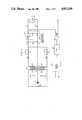
- FIG. 1is a circuit schematic of a regulated quasi resonant double ended DC to DC converter operating in a fixed pulse, variable interval mode of operation and embodying the principles of the invention
- FIG. 2is a circuit schematic power train of a quasi resonant half bridge DC to DC converter embodying the principles of the invention
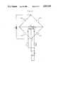
- FIG. 5is an equivalent circuit useful in describing the operation of the circuit disclosed in FIG. 1.
- a push pull or double ended DC to DC converter adopted to operate in a quasi resonant modeis shown in FIG. 1.
- a DC voltage source 10 connected to the input terminals 11 and 12is alternately applied to the primary windings 21 and 22 of power transformer 20 through the alternate ON-OFF switching of power transistors 14 and 15, respectively.
- the secondary windings 23 and 24are coupled through rectifying diodes 34 and 35 to terminal 4 of a resonating capacitor 40 respectively which is in turn connected across the output filter and load transformation network 41 which is shown as comprising inductor 42 and capacitor 43.
- a load 50 to be energizedis connected to output terminals 31 and 32 so as to shunt filter capacitor 43.
- a control circuit for voltage regulationis shown which operates the switching of the two power switching transistors 14 and 15 in a variable frequency mode of operation.
- a replica of the output voltage sensed at output terminal 31is coupled to a comparaor 46 which is also connected to receive a reference voltage.
- the output error signal of the comparator 46is applied to a duty cycle control 47 which may comprise a voltage controlled oscillator whose frequency is responsive to the magnitude of the error signal.
- the duty cycle control outputis applied to a switch drive circuit 48 which may comprise a monostable multivibrator in which one output is fixed in duration while the other output varies in duration in order to accomplish regulation of the output voltage.
- the multivibrator outputis applied through a toggle gate which alternates the drive to the a and b terminals and hence to the base inputs a and b of the two switching transistors 14 and 15. While bipolar transistors are shown it is to be understood that power MOSFETS may be used with drive applied to the gate terminals.
- the power transformer 20is preferably designed to have the leakage reactances 38 and 39, which appear most prominently on the secondary windings 23 and 24, and which are designed to be an integeral part of the resonant circuitry of converter. Discrete inductances, if needed, may be used in place of or to supplement this leakage inductance.
- Each of the rectifying diodes 34 and 35include the parasitic capacitances 36 and 37 which also are an integeral part of the resonant converter operation. These two capacitive elements may also be supplemented or replaced by discrete capacitors if needed.
- Each rectifying diode 34 and 35is connected to terminal 4 of a resonating capacitor 40 whose capacitance is selected so that each series connection of a leakage inductance, parasitic capacitance and resonating capacitor resonates in response to a voltage pulse drive supplied by an associated one of the switching transistors 14 and 15.
- the other oppositely phased resonant circuit not being driven at that timeoperates in a filter mode to reduce harmonics applied to the resonating capacitor 40 and to the output.
- the output filter 41is designed to have an input impedance substantially exceeding the impedance of the resonant circuit driving it and hence transmits only the DC voltage of the resonating capacitor to the output load 50. While filter 41 is shown as a single stage filter, multi stage filters with similar characteristics may also be used.
- the converter circuitbasically operates in a two phase mode of resonant operation in which a separate quasi resonant signal processing event is independently associated with each switching transistor 14 and 15.
- a current flow in either one of the switching transistors 14 and 15causes a current to flow in its associated quasi resonant circuit.
- the current flow in the resonant circuitresonates by charging the resonating capacitor 40 first in one direction and then by continued resonant action discharges the resonating capacitor 40 in the opposite direction.
- output load currentis supplied through the rectifying diodes 34 and 35.
- Circuit continuity during the simultaneous nonconduction of the switching transducers 14 and 15is provided by the simultaneous forward conduction action of the rectifying diode 35 and 34 respectively. This sequence of operation is followed in each individual half phase of operation of the push pull circuit, with each oppositely phased quasi resonant circuit operating alternately and independently with respect to one another.
- the current flowing through transistor 14has a sinusoidal wave form and continues conducting in duration sufficiently to complete a full half cycle current waveform for which eventually terminates at t 3 .
- Thisis shown in current waveform in FIG. 4, part A which extends from t 0 to t 3 .
- a current shown by waveform 470 in FIG. 4, part 6is flowing through the rectifying diode 35 and at the time t 0 has a value equal to 1/2 the output load circuit. It steadily increases in value as shown by waveform 470 in FIG. 4, Part G of a value equaling the load current at time t 1 and eventually to a peak value at time T 2 . All the current exceeding the load current is directed into the resonating capacitor 40 as shown by waveform 460 in FIG. 4, Part F.
- Rectifying diode 34also conducts a current equaling 1/2 the load circuit at time t 0 as shown by waveform 480 in FIG. 4, Part H. This current is decaying and reaches zero value at time t 1 . Since the output filter inductor 42 acts as a constant current sink only a current equal to the steady state load current is transmitted into the load 50 and any excess current is directed into the resonating capacitor 40.
- This charging currentis shown by waveform 460 in FIG. 4, Part F, and is shown extending between times t 1 and t 4 . It completes a 3/4 period sine wave function at time t 3 which is followed by a fixed charging current which abruptly terminaters at t 4 .
- the transistor 14is biased nonconducting and current flow in its related circuit loop shown by waveform 410 ceases.
- current flow in the rectifying diode 35 shown by waveform 470has also dropped to zero.
- the charging current in the resonating capacitor 40stabilizes at the negative value of the load circuit as shown by level 461 in waveform 460 shown in FIG. 4, Part F.
- the rectifying diodes 34 and 35are both individually conducting a current equaling half the load current thereby providing a flyback current path to provide the continuous load current to the filter inductor 42.
- the current flow in the resonating capacitor 40drops abruptly to zero at the end of the half cycle as shown by waveform 460 and the voltage drop across each transistor 14 and 15 is equal to the input voltage as shown by voltage levels 432 and 442 in FIG. 4, Parts C and D respectively.
- the quasi resonant signal actionis advantageously confined to the secondary part of the converter circuit and that since each half cycle is sufficient in duration to permit the desired resonant action, the variable pulse width conduction interval on the primary side may be operated over a considerable range without adversely affecting the resonant properties of the circuit.
- a particular feature of this arrangementis the parasitic capacitance of the rectifying diode that shunts the rectifying diode and the leakage inductance associated with the idle resonant circuit which in any half cycle functions as a harmonic filter and limits the application of harmonics to the resonating capacitor 40.
- a half bridge embodiment of a power train embodying the principles of the inventionis shown in a schematic form in FIG. 2 in which two alternately conducting transistor switches 214 and 215 are shown connected in series connection with this series connection being connected in shunt with the DC voltage source 210 and the input voltage terminals 211 and 212.
- the switched output voltageis taken from the junction node 216 of the two switching transistors 214 and 215 and is applied to the primary winding 221 of transformer 220.
- a resonant secondary circuit identical to the FIG. 1is alternately energized by secondary windings 223 and 224.
- the operation of half bridge invertersis well known to those skilled in the art, and hence its operation need not be discussed in detail.
- FIG. 3A full bridge embodiment of the inverter is shown in FIG. 3 which includes four switching transistors 314, 315, 317 and 318 in which two opposing switches are operated in phase with one another to apply alternately directed energy pulses to the primary winding 321 of transformer 320.
- the secondary portion of the circuitis substantially identical in circuitry and operation to that shown for FIG. 1.
- FIG. 5An equivalent circuit showing the electrical funtional operation of the circuit schematic of FIG. 1 is shown in FIG. 5.
- the power transformeris not shown and hence a unity transformation ratio is assumed.
- the two oppositely phased resonant circuitsare shown as having oppositely phased voltage pulse source circuits 514 and 515 coupled to them.
- the first resonant circuit coupled to voltage pulse source 514includes a switch 535 which is operated as a diode switch, a capacitance 537 shunting the switch and an inductance 539.
- the second resonant circuit coupled to voltage pulse source 515includes the diode switch 534, a capacitance 536 shunting the switch and an inductance 538.
- the two pulse voltage sourcesare operated during oppositely phased intervals as that the two oppositely phased resonant circuits are pulsed or pumped alternately during oppositely phased intervals.
- Each resonant circuitshares a common resonant capacitor 540 which is connected at the input to the output filter 541 which includes inductor 542 and capacitor 543.
- the inductor of that circuitresonates within resonant capacitor 540 for substantially a half cycle of operation with subsequent resonance being cut off by the opening of the associated/switch diode.
- V MAXis the maximum voltage applied by the source (514) to the resonant network.
- L matchingis the inductance of output filter 41.
- V CRis the voltage across the resonating capacitor C R 540.
- I CRis the current through the resonating capacitor C R 540.
- L Ris the leakage reactance 539 or 538 forming part of each resonant
- V LRis the voltage across the leakage rectance L R , 538 or 539.
- I LRis the current through the leakage rectance L R , 538 or 539.
Landscapes
- Engineering & Computer Science (AREA)
- Power Engineering (AREA)
- Physics & Mathematics (AREA)
- Electromagnetism (AREA)
- Dc-Dc Converters (AREA)
Abstract
Description
Claims (9)
Priority Applications (5)
| Application Number | Priority Date | Filing Date | Title |
|---|---|---|---|
| US07/043,008US4823249A (en) | 1987-04-27 | 1987-04-27 | High-frequency resonant power converter |
| CA000562761ACA1301837C (en) | 1987-04-27 | 1988-03-29 | High frequency resonant power converter |
| EP88303521AEP0289196A3 (en) | 1987-04-27 | 1988-04-19 | High frequency resonant power converter |
| KR1019880004686AKR880013300A (en) | 1987-04-27 | 1988-04-25 | High frequency resonant power converter |
| JP63102845AJPH0197169A (en) | 1987-04-27 | 1988-04-27 | High-frequency resonance type power converter |
Applications Claiming Priority (1)
| Application Number | Priority Date | Filing Date | Title |
|---|---|---|---|
| US07/043,008US4823249A (en) | 1987-04-27 | 1987-04-27 | High-frequency resonant power converter |
Publications (1)
| Publication Number | Publication Date |
|---|---|
| US4823249Atrue US4823249A (en) | 1989-04-18 |
Family
ID=21924965
Family Applications (1)
| Application Number | Title | Priority Date | Filing Date |
|---|---|---|---|
| US07/043,008Expired - LifetimeUS4823249A (en) | 1987-04-27 | 1987-04-27 | High-frequency resonant power converter |
Country Status (5)
| Country | Link |
|---|---|
| US (1) | US4823249A (en) |
| EP (1) | EP0289196A3 (en) |
| JP (1) | JPH0197169A (en) |
| KR (1) | KR880013300A (en) |
| CA (1) | CA1301837C (en) |
Cited By (81)
| Publication number | Priority date | Publication date | Assignee | Title |
|---|---|---|---|---|
| US4959765A (en)* | 1988-02-24 | 1990-09-25 | Agence Spatiale Europeenne | DC to DC converter using quasi-resonance |
| US4984146A (en)* | 1990-03-27 | 1991-01-08 | International Business Machines Corporation | Suppression of radiated EMI for power supplies |
| US5113334A (en)* | 1987-10-29 | 1992-05-12 | Rifala Pty. Ltd. | High efficiency converter |
| US5132888A (en)* | 1991-01-07 | 1992-07-21 | Unisys Corporation | Interleaved bridge converter |
| US5177675A (en)* | 1991-10-16 | 1993-01-05 | Shindengen Archer Corp. | Zero voltage, zero current, resonant converter |
| US5396410A (en)* | 1990-01-31 | 1995-03-07 | Kabushiki Kaisha Toshiba | Zero current switching resonant converter |
| US5459650A (en)* | 1991-09-25 | 1995-10-17 | Yamaha Corporation | Power supply circuit |
| US5485362A (en)* | 1993-09-08 | 1996-01-16 | Eos Corporation | Resonant power converter for changing the magnitude of a DC voltage |
| US5521807A (en)* | 1992-12-31 | 1996-05-28 | Interpoint Corporation | DC-To-DC converter with secondary flyback core reset |
| US5546295A (en)* | 1994-02-24 | 1996-08-13 | Rotron Incorporated | Electrical power converter, power supply, and inverter with series-connected switching circuits |
| US5568369A (en)* | 1992-10-15 | 1996-10-22 | Ant Nachrichtentechnik Gmbh | Method for operating a voltage converter, and a voltage converter and its application |
| US5872703A (en)* | 1997-08-25 | 1999-02-16 | The Charles Machine Works, Inc. | System and method for regulating power in tank circuits having a bridge configuration |
| US5903446A (en)* | 1995-08-30 | 1999-05-11 | Gaia Converter | Direct current voltage converter with soft switching |
| US5903448A (en)* | 1997-08-20 | 1999-05-11 | Lucent Technologies Inc. | Four quadrant flyback converter, method of operation thereof and power plant employing the same |
| US5909362A (en)* | 1998-01-12 | 1999-06-01 | Eldec Corporation | Resonant power converter |
| US6240318B1 (en) | 1998-10-27 | 2001-05-29 | Richard P. Phillips | Transcutaneous energy transmission system with full wave Class E rectifier |
| US6294900B1 (en)* | 1998-03-11 | 2001-09-25 | Simon R. Greenwood | Bi-directional AC or DC voltage regulator |
| US6377481B1 (en) | 1999-06-30 | 2002-04-23 | Peco Ii, Inc. | Power supply including diode recovery current suppression circuit |
| US6442047B1 (en) | 1999-10-08 | 2002-08-27 | Lambda Electronics, Inc. | Power conversion apparatus and methods with reduced current and voltage switching |
| US20030067791A1 (en)* | 2001-09-04 | 2003-04-10 | Reinhold Elferich | Regulating device for a resonant converter |
| US20030086282A1 (en)* | 2001-11-02 | 2003-05-08 | Jianhong Zeng | DC-to-DC converter |
| US20030198067A1 (en)* | 2002-04-18 | 2003-10-23 | Innovative Technology Licensing, Llc | Core structure and interleaved DC-DC converter topology |
| US20040022073A1 (en)* | 2000-04-03 | 2004-02-05 | Nielsen Stig Munk | Resonant converter having a self inductance |
| US6693804B2 (en)* | 2001-01-22 | 2004-02-17 | Kabushiki Kaisha Toyota Jidoshokki | Switching power supply circuit |
| US6807073B1 (en) | 2001-05-02 | 2004-10-19 | Oltronics, Inc. | Switching type power converter circuit and method for use therein |
| US20050024179A1 (en)* | 2002-04-18 | 2005-02-03 | Rockwell Scientific Licensing, Llc | Extended E matrix integrated magnetics (MIM) core |
| US20060038650A1 (en)* | 2004-08-19 | 2006-02-23 | Rockwell Scientific Licensing, Llc | Vertical winding structures for planar magnetic switched-mode power converters |
| US20060038649A1 (en)* | 2004-08-19 | 2006-02-23 | Rockwell Scientific Licensing, Llc | Winding structure for efficient switch-mode power converters |
| US20060187684A1 (en)* | 2005-02-08 | 2006-08-24 | Sriram Chandrasekaran | Power converter employing integrated magnetics with a current multiplier rectifier and method of operating the same |
| US20060198173A1 (en)* | 2005-02-23 | 2006-09-07 | Rozman Allen F | Control circuit for a depletion mode switch and method of operating the same |
| US20070046218A1 (en)* | 2005-08-26 | 2007-03-01 | Hon Hai Precision Industry Co., Ltd. | Apparatus and method for driving plural lamps |
| US20070114979A1 (en)* | 2005-02-23 | 2007-05-24 | Sriram Chandrasekaran | Power converter employing a tapped inductor and integrated magnetics and method of operating the same |
| US20070185754A1 (en)* | 2006-02-07 | 2007-08-09 | Sap Ag | Task responsibility system |
| US20080054874A1 (en)* | 2006-08-31 | 2008-03-06 | Sriram Chandrasekaran | Power Converter Employing Regulators with a Coupled Inductor |
| US20080130322A1 (en)* | 2006-12-01 | 2008-06-05 | Artusi Daniel A | Power system with power converters having an adaptive controller |
| US20080130321A1 (en)* | 2006-12-01 | 2008-06-05 | Artusi Daniel A | Power converter with an adaptive controller and method of operating the same |
| US20080150666A1 (en)* | 2005-02-23 | 2008-06-26 | Sriram Chandrasekaran | Power Converter Employing a Tapped Inductor and Integrated Magnetics and Method of Operating the Same |
| US20080232141A1 (en)* | 2006-12-01 | 2008-09-25 | Artusi Daniel A | Power System with Power Converters Having an Adaptive Controller |
| US20080315852A1 (en)* | 2007-06-19 | 2008-12-25 | Chandrasekaran Jayaraman | System and Method for Estimating Input Power for a Power Processing Circuit |
| US20090097290A1 (en)* | 2007-03-14 | 2009-04-16 | Sriram Chandrasekaran | Isolated Power Converter |
| US7558083B2 (en) | 1997-01-24 | 2009-07-07 | Synqor, Inc. | High efficiency power converter |
| US7564702B2 (en) | 1997-01-24 | 2009-07-21 | Synqor, Inc. | High efficiency power converter |
| US20090290385A1 (en)* | 2008-05-21 | 2009-11-26 | Flextronics Ap, Llc | Resonant power factor correction converter |
| US20090310384A1 (en)* | 2008-06-12 | 2009-12-17 | Bahman Sharifipour | AC-DC input adapter |
| US20100165667A1 (en)* | 2006-12-01 | 2010-07-01 | Artusi Daniel A | Power System with Power Converters Having an Adaptive Controller |
| US20100182806A1 (en)* | 2009-01-19 | 2010-07-22 | Paul Garrity | Controller for a Power Converter |
| US20100322441A1 (en)* | 2009-06-23 | 2010-12-23 | Flextronics Ap, Llc | Notebook power supply with integrated subwoofer |
| US20100321958A1 (en)* | 2009-06-17 | 2010-12-23 | Antony Brinlee | Power Converter Employing a Variable Switching Frequency and a Magnetic Device with a Non-Uniform Gap |
| US20110134664A1 (en)* | 2009-12-03 | 2011-06-09 | Berghegger Ralf Schroeder Genannt | Startup Circuit and Power Converter Employing the Same |
| US20110149607A1 (en)* | 2009-12-18 | 2011-06-23 | Aaron Jungreis | Controller for a Power Converter |
| US20110182089A1 (en)* | 2010-01-22 | 2011-07-28 | Genannt Berghegger Ralf Schroeder | Controller for a Power Converter and Method of Operating the Same |
| US20110261590A1 (en)* | 2010-04-22 | 2011-10-27 | Flextronics Ap, Llc | Two stage resonant converter |
| US8441810B2 (en) | 2010-11-09 | 2013-05-14 | Flextronics Ap, Llc | Cascade power system architecture |
| US8488340B2 (en) | 2010-08-27 | 2013-07-16 | Flextronics Ap, Llc | Power converter with boost-buck-buck configuration utilizing an intermediate power regulating circuit |
| US8520410B2 (en) | 2010-11-09 | 2013-08-27 | Flextronics Ap, Llc | Virtual parametric high side MOSFET driver |
| CN103337964A (en)* | 2013-04-27 | 2013-10-02 | 南京航空航天大学 | Ultrahigh frequency isolation push-pull resonant power converter |
| US8638578B2 (en) | 2009-08-14 | 2014-01-28 | Power System Technologies, Ltd. | Power converter including a charge pump employable in a power adapter |
| US8643222B2 (en) | 2009-06-17 | 2014-02-04 | Power Systems Technologies Ltd | Power adapter employing a power reducer |
| US8767418B2 (en) | 2010-03-17 | 2014-07-01 | Power Systems Technologies Ltd. | Control system for a power converter and method of operating the same |
| US8792256B2 (en) | 2012-01-27 | 2014-07-29 | Power Systems Technologies Ltd. | Controller for a switch and method of operating the same |
| US8792257B2 (en) | 2011-03-25 | 2014-07-29 | Power Systems Technologies, Ltd. | Power converter with reduced power dissipation |
| US8842450B2 (en) | 2011-04-12 | 2014-09-23 | Flextronics, Ap, Llc | Power converter using multiple phase-shifting quasi-resonant converters |
| US9019061B2 (en) | 2009-03-31 | 2015-04-28 | Power Systems Technologies, Ltd. | Magnetic device formed with U-shaped core pieces and power converter employing the same |
| DE102013223194A1 (en)* | 2013-11-14 | 2015-05-21 | Robert Bosch Gmbh | DC-DC converter, method for clocking a converter of a DC-DC converter and method for converting DC voltage |
| US9054602B2 (en)* | 2010-12-10 | 2015-06-09 | Helen Pollock | Resonant circuit with constant current characteristics |
| US9077248B2 (en) | 2009-06-17 | 2015-07-07 | Power Systems Technologies Ltd | Start-up circuit for a power adapter |
| CN104782033A (en)* | 2012-11-09 | 2015-07-15 | 株式会社村田制作所 | Soft-start for resonant converters |
| US9088216B2 (en) | 2009-01-19 | 2015-07-21 | Power Systems Technologies, Ltd. | Controller for a synchronous rectifier switch |
| US9099232B2 (en) | 2012-07-16 | 2015-08-04 | Power Systems Technologies Ltd. | Magnetic device and power converter employing the same |
| US9106130B2 (en) | 2012-07-16 | 2015-08-11 | Power Systems Technologies, Inc. | Magnetic device and power converter employing the same |
| US20150311807A1 (en)* | 2014-04-29 | 2015-10-29 | Valeo Equipements Electriques Moteur | Power supply and method for controlling a power supply |
| US9190898B2 (en) | 2012-07-06 | 2015-11-17 | Power Systems Technologies, Ltd | Controller for a power converter and method of operating the same |
| US9197132B2 (en) | 2006-12-01 | 2015-11-24 | Flextronics International Usa, Inc. | Power converter with an adaptive controller and method of operating the same |
| US9214264B2 (en) | 2012-07-16 | 2015-12-15 | Power Systems Technologies, Ltd. | Magnetic device and power converter employing the same |
| US9240712B2 (en) | 2012-12-13 | 2016-01-19 | Power Systems Technologies Ltd. | Controller including a common current-sense device for power switches of a power converter |
| US9246391B2 (en) | 2010-01-22 | 2016-01-26 | Power Systems Technologies Ltd. | Controller for providing a corrected signal to a sensed peak current through a circuit element of a power converter |
| US9379629B2 (en) | 2012-07-16 | 2016-06-28 | Power Systems Technologies, Ltd. | Magnetic device and power converter employing the same |
| US20170324338A1 (en)* | 2013-10-23 | 2017-11-09 | Toshiba Tec Kabushiki Kaisha | Power conversion device and method of operating a power conversion device |
| US10199950B1 (en) | 2013-07-02 | 2019-02-05 | Vlt, Inc. | Power distribution architecture with series-connected bus converter |
| US10389104B1 (en)* | 2015-01-09 | 2019-08-20 | Clemson University | Circuit breaker for DC circuits using coupled induction |
| US20220209672A1 (en)* | 2019-11-29 | 2022-06-30 | Shandong University Of Science And Technology | High-gain quasi-resonant dc-dc converter based on voltage doubling rectifier circuit |
Families Citing this family (2)
| Publication number | Priority date | Publication date | Assignee | Title |
|---|---|---|---|---|
| US5291382A (en)* | 1991-04-10 | 1994-03-01 | Lambda Electronics Inc. | Pulse width modulated DC/DC converter with reduced ripple current coponent stress and zero voltage switching capability |
| US5303138A (en)* | 1993-04-29 | 1994-04-12 | At&T Bell Laboratories | Low loss synchronous rectifier for application to clamped-mode power converters |
Citations (7)
| Publication number | Priority date | Publication date | Assignee | Title |
|---|---|---|---|---|
| US3089077A (en)* | 1958-10-06 | 1963-05-07 | Basler Electric Co | Transistor converters |
| JPS5846874A (en)* | 1981-09-12 | 1983-03-18 | Hitachi Heating Appliance Co Ltd | automotive converter |
| US4415959A (en)* | 1981-03-20 | 1983-11-15 | Vicor Corporation | Forward converter switching at zero current |
| US4628426A (en)* | 1985-10-31 | 1986-12-09 | General Electric Company | Dual output DC-DC converter with independently controllable output voltages |
| US4685041A (en)* | 1985-03-11 | 1987-08-04 | American Telephone And Telegraph Company, At&T Bell Laboratories | Resonant rectifier circuit |
| US4720667A (en)* | 1986-06-20 | 1988-01-19 | Lee Fred C | Zero-current switching quasi-resonant converters operating in a full-wave mode |
| US4720668A (en)* | 1986-06-20 | 1988-01-19 | Lee Fred C | Zero-voltage switching quasi-resonant converters |
Family Cites Families (3)
| Publication number | Priority date | Publication date | Assignee | Title |
|---|---|---|---|---|
| GB1431262A (en)* | 1971-12-16 | 1976-04-07 | Advance Electronics Ltd | Power supply apparatus |
| US4017784A (en)* | 1976-05-17 | 1977-04-12 | Litton Systems, Inc. | DC to DC converter |
| JPS5746673A (en)* | 1980-09-05 | 1982-03-17 | Kosuke Harada | Dc-dc converter |
- 1987
- 1987-04-27USUS07/043,008patent/US4823249A/ennot_activeExpired - Lifetime
- 1988
- 1988-03-29CACA000562761Apatent/CA1301837C/ennot_activeExpired - Fee Related
- 1988-04-19EPEP88303521Apatent/EP0289196A3/ennot_activeWithdrawn
- 1988-04-25KRKR1019880004686Apatent/KR880013300A/ennot_activeWithdrawn
- 1988-04-27JPJP63102845Apatent/JPH0197169A/enactivePending
Patent Citations (7)
| Publication number | Priority date | Publication date | Assignee | Title |
|---|---|---|---|---|
| US3089077A (en)* | 1958-10-06 | 1963-05-07 | Basler Electric Co | Transistor converters |
| US4415959A (en)* | 1981-03-20 | 1983-11-15 | Vicor Corporation | Forward converter switching at zero current |
| JPS5846874A (en)* | 1981-09-12 | 1983-03-18 | Hitachi Heating Appliance Co Ltd | automotive converter |
| US4685041A (en)* | 1985-03-11 | 1987-08-04 | American Telephone And Telegraph Company, At&T Bell Laboratories | Resonant rectifier circuit |
| US4628426A (en)* | 1985-10-31 | 1986-12-09 | General Electric Company | Dual output DC-DC converter with independently controllable output voltages |
| US4720667A (en)* | 1986-06-20 | 1988-01-19 | Lee Fred C | Zero-current switching quasi-resonant converters operating in a full-wave mode |
| US4720668A (en)* | 1986-06-20 | 1988-01-19 | Lee Fred C | Zero-voltage switching quasi-resonant converters |
Non-Patent Citations (8)
| Title |
|---|
| "Low-Profile High-Frequency Off-Line Quasi-Resonant Converter", by Albert M. Heyman, IEEE Applied Power Electronics Conference (San Diego) 1987 Mar. 2-6, pp. 157-165. |
| "Practical Resonant Power Converters-Theory and Application", Part II-The Resonant Switch Concept, by P. C. Todd and R. W. Lutz, Power Technics Magazine, May 1986, pp. 29-35. |
| "Secondary-Side Resonance For High-Frequency Power Conversion", by K. Liu and F. C. Lee, IEEE Applied Power Electronics Conference, (New Orleans) Apr. 28-May 1, 1986, pp. 83-89. |
| "Two-Megahertz Off-Line Hybridized Quasi-Resonant Converter", by D. C. Hopkins, M. M. Jovanovic, F. C. Lee and F. W. Stephenson, IEEE Applied Power Electronics Conference (San Diego) 1987 Mar. 2-6, pp. 105-114. |
| Low Profile High Frequency Off Line Quasi Resonant Converter , by Albert M. Heyman, IEEE Applied Power Electronics Conference (San Diego) 1987 Mar. 2 6, pp. 157 165.* |
| Practical Resonant Power Converters Theory and Application , Part II The Resonant Switch Concept, by P. C. Todd and R. W. Lutz, Power Technics Magazine, May 1986, pp. 29 35.* |
| Secondary Side Resonance For High Frequency Power Conversion , by K. Liu and F. C. Lee, IEEE Applied Power Electronics Conference, (New Orleans) Apr. 28 May 1, 1986, pp. 83 89.* |
| Two Megahertz Off Line Hybridized Quasi Resonant Converter , by D. C. Hopkins, M. M. Jovanovic, F. C. Lee and F. W. Stephenson, IEEE Applied Power Electronics Conference (San Diego) 1987 Mar. 2 6, pp. 105 114.* |
Cited By (131)
| Publication number | Priority date | Publication date | Assignee | Title |
|---|---|---|---|---|
| US5113334A (en)* | 1987-10-29 | 1992-05-12 | Rifala Pty. Ltd. | High efficiency converter |
| US4959765A (en)* | 1988-02-24 | 1990-09-25 | Agence Spatiale Europeenne | DC to DC converter using quasi-resonance |
| US5396410A (en)* | 1990-01-31 | 1995-03-07 | Kabushiki Kaisha Toshiba | Zero current switching resonant converter |
| US4984146A (en)* | 1990-03-27 | 1991-01-08 | International Business Machines Corporation | Suppression of radiated EMI for power supplies |
| US5132888A (en)* | 1991-01-07 | 1992-07-21 | Unisys Corporation | Interleaved bridge converter |
| US5459650A (en)* | 1991-09-25 | 1995-10-17 | Yamaha Corporation | Power supply circuit |
| US5177675A (en)* | 1991-10-16 | 1993-01-05 | Shindengen Archer Corp. | Zero voltage, zero current, resonant converter |
| US5568369A (en)* | 1992-10-15 | 1996-10-22 | Ant Nachrichtentechnik Gmbh | Method for operating a voltage converter, and a voltage converter and its application |
| US5521807A (en)* | 1992-12-31 | 1996-05-28 | Interpoint Corporation | DC-To-DC converter with secondary flyback core reset |
| US5485362A (en)* | 1993-09-08 | 1996-01-16 | Eos Corporation | Resonant power converter for changing the magnitude of a DC voltage |
| US5546295A (en)* | 1994-02-24 | 1996-08-13 | Rotron Incorporated | Electrical power converter, power supply, and inverter with series-connected switching circuits |
| US5903446A (en)* | 1995-08-30 | 1999-05-11 | Gaia Converter | Direct current voltage converter with soft switching |
| US8493751B2 (en) | 1997-01-24 | 2013-07-23 | Synqor, Inc. | High efficiency power converter |
| US8023290B2 (en) | 1997-01-24 | 2011-09-20 | Synqor, Inc. | High efficiency power converter |
| US7564702B2 (en) | 1997-01-24 | 2009-07-21 | Synqor, Inc. | High efficiency power converter |
| US7558083B2 (en) | 1997-01-24 | 2009-07-07 | Synqor, Inc. | High efficiency power converter |
| US9143042B2 (en) | 1997-01-24 | 2015-09-22 | Synqor, Inc. | High efficiency power converter |
| US5903448A (en)* | 1997-08-20 | 1999-05-11 | Lucent Technologies Inc. | Four quadrant flyback converter, method of operation thereof and power plant employing the same |
| US5872703A (en)* | 1997-08-25 | 1999-02-16 | The Charles Machine Works, Inc. | System and method for regulating power in tank circuits having a bridge configuration |
| US5909362A (en)* | 1998-01-12 | 1999-06-01 | Eldec Corporation | Resonant power converter |
| US6294900B1 (en)* | 1998-03-11 | 2001-09-25 | Simon R. Greenwood | Bi-directional AC or DC voltage regulator |
| US6240318B1 (en) | 1998-10-27 | 2001-05-29 | Richard P. Phillips | Transcutaneous energy transmission system with full wave Class E rectifier |
| US6377481B1 (en) | 1999-06-30 | 2002-04-23 | Peco Ii, Inc. | Power supply including diode recovery current suppression circuit |
| US6442047B1 (en) | 1999-10-08 | 2002-08-27 | Lambda Electronics, Inc. | Power conversion apparatus and methods with reduced current and voltage switching |
| US20040022073A1 (en)* | 2000-04-03 | 2004-02-05 | Nielsen Stig Munk | Resonant converter having a self inductance |
| US6693804B2 (en)* | 2001-01-22 | 2004-02-17 | Kabushiki Kaisha Toyota Jidoshokki | Switching power supply circuit |
| US6807073B1 (en) | 2001-05-02 | 2004-10-19 | Oltronics, Inc. | Switching type power converter circuit and method for use therein |
| US20050036340A1 (en)* | 2001-05-02 | 2005-02-17 | Oltronics | Switching type power converter circuit and method for use therein |
| US7002815B2 (en) | 2001-05-02 | 2006-02-21 | Oltronics, Inc. | Switching type power converter circuit and method for use therein |
| US6829151B2 (en)* | 2001-09-04 | 2004-12-07 | Koninklijke Philips Electronics N.V. | Regulating device for a resonant converter |
| US20030067791A1 (en)* | 2001-09-04 | 2003-04-10 | Reinhold Elferich | Regulating device for a resonant converter |
| US20030086282A1 (en)* | 2001-11-02 | 2003-05-08 | Jianhong Zeng | DC-to-DC converter |
| US6778410B2 (en)* | 2001-11-02 | 2004-08-17 | Delta Electronics, Inc. | DC-to-DC converter |
| US7046523B2 (en)* | 2002-04-18 | 2006-05-16 | Coldwatt, Inc. | Core structure and interleaved DC—DC converter topology |
| US7633369B2 (en) | 2002-04-18 | 2009-12-15 | Flextronics International Usa, Inc. | Extended E matrix integrated magnetics (MIM) core |
| US20100091522A1 (en)* | 2002-04-18 | 2010-04-15 | Sriram Chandrasekaran | Extended E Matrix Integrated Magnetics (MIM) Core |
| US20050024179A1 (en)* | 2002-04-18 | 2005-02-03 | Rockwell Scientific Licensing, Llc | Extended E matrix integrated magnetics (MIM) core |
| US8134443B2 (en) | 2002-04-18 | 2012-03-13 | Flextronics International Usa, Inc. | Extended E matrix integrated magnetics (MIM) core |
| US7280026B2 (en) | 2002-04-18 | 2007-10-09 | Coldwatt, Inc. | Extended E matrix integrated magnetics (MIM) core |
| US20030198067A1 (en)* | 2002-04-18 | 2003-10-23 | Innovative Technology Licensing, Llc | Core structure and interleaved DC-DC converter topology |
| US20060038650A1 (en)* | 2004-08-19 | 2006-02-23 | Rockwell Scientific Licensing, Llc | Vertical winding structures for planar magnetic switched-mode power converters |
| US7554430B2 (en) | 2004-08-19 | 2009-06-30 | Flextronics International Usa, Inc. | Vertical winding structures for planar magnetic switched-mode power converters |
| US20080111657A1 (en)* | 2004-08-19 | 2008-05-15 | Vivek Mehrotra | Vertical Winding Structures for Planar Magnetic Switched-Mode Power Converters |
| US7321283B2 (en) | 2004-08-19 | 2008-01-22 | Coldwatt, Inc. | Vertical winding structures for planar magnetic switched-mode power converters |
| US20060038649A1 (en)* | 2004-08-19 | 2006-02-23 | Rockwell Scientific Licensing, Llc | Winding structure for efficient switch-mode power converters |
| US7427910B2 (en) | 2004-08-19 | 2008-09-23 | Coldwatt, Inc. | Winding structure for efficient switch-mode power converters |
| US7675764B2 (en) | 2005-02-08 | 2010-03-09 | Flextronics International Usa, Inc. | Power converter employing integrated magnetics with a current multiplier rectifier and method of operating the same |
| US20060187684A1 (en)* | 2005-02-08 | 2006-08-24 | Sriram Chandrasekaran | Power converter employing integrated magnetics with a current multiplier rectifier and method of operating the same |
| US7417875B2 (en) | 2005-02-08 | 2008-08-26 | Coldwatt, Inc. | Power converter employing integrated magnetics with a current multiplier rectifier and method of operating the same |
| US7385375B2 (en) | 2005-02-23 | 2008-06-10 | Coldwatt, Inc. | Control circuit for a depletion mode switch and method of operating the same |
| US20070114979A1 (en)* | 2005-02-23 | 2007-05-24 | Sriram Chandrasekaran | Power converter employing a tapped inductor and integrated magnetics and method of operating the same |
| US20060198173A1 (en)* | 2005-02-23 | 2006-09-07 | Rozman Allen F | Control circuit for a depletion mode switch and method of operating the same |
| US7876191B2 (en) | 2005-02-23 | 2011-01-25 | Flextronics International Usa, Inc. | Power converter employing a tapped inductor and integrated magnetics and method of operating the same |
| US20080150666A1 (en)* | 2005-02-23 | 2008-06-26 | Sriram Chandrasekaran | Power Converter Employing a Tapped Inductor and Integrated Magnetics and Method of Operating the Same |
| US7298118B2 (en) | 2005-02-23 | 2007-11-20 | Coldwatt, Inc. | Power converter employing a tapped inductor and integrated magnetics and method of operating the same |
| US7550929B2 (en)* | 2005-08-26 | 2009-06-23 | Hon Hai Precision Industry Co., Ltd. | Power system and method for driving plural lamps |
| US20070046218A1 (en)* | 2005-08-26 | 2007-03-01 | Hon Hai Precision Industry Co., Ltd. | Apparatus and method for driving plural lamps |
| US20070185754A1 (en)* | 2006-02-07 | 2007-08-09 | Sap Ag | Task responsibility system |
| US8125205B2 (en) | 2006-08-31 | 2012-02-28 | Flextronics International Usa, Inc. | Power converter employing regulators with a coupled inductor |
| US20080054874A1 (en)* | 2006-08-31 | 2008-03-06 | Sriram Chandrasekaran | Power Converter Employing Regulators with a Coupled Inductor |
| US20100165667A1 (en)* | 2006-12-01 | 2010-07-01 | Artusi Daniel A | Power System with Power Converters Having an Adaptive Controller |
| US8477514B2 (en) | 2006-12-01 | 2013-07-02 | Flextronics International Usa, Inc. | Power system with power converters having an adaptive controller |
| US7675758B2 (en) | 2006-12-01 | 2010-03-09 | Flextronics International Usa, Inc. | Power converter with an adaptive controller and method of operating the same |
| US7667986B2 (en) | 2006-12-01 | 2010-02-23 | Flextronics International Usa, Inc. | Power system with power converters having an adaptive controller |
| US20080130322A1 (en)* | 2006-12-01 | 2008-06-05 | Artusi Daniel A | Power system with power converters having an adaptive controller |
| US7675759B2 (en) | 2006-12-01 | 2010-03-09 | Flextronics International Usa, Inc. | Power system with power converters having an adaptive controller |
| US9197132B2 (en) | 2006-12-01 | 2015-11-24 | Flextronics International Usa, Inc. | Power converter with an adaptive controller and method of operating the same |
| US20080232141A1 (en)* | 2006-12-01 | 2008-09-25 | Artusi Daniel A | Power System with Power Converters Having an Adaptive Controller |
| US20080130321A1 (en)* | 2006-12-01 | 2008-06-05 | Artusi Daniel A | Power converter with an adaptive controller and method of operating the same |
| US7889517B2 (en) | 2006-12-01 | 2011-02-15 | Flextronics International Usa, Inc. | Power system with power converters having an adaptive controller |
| US8502520B2 (en) | 2007-03-14 | 2013-08-06 | Flextronics International Usa, Inc | Isolated power converter |
| US20090097290A1 (en)* | 2007-03-14 | 2009-04-16 | Sriram Chandrasekaran | Isolated Power Converter |
| US7906941B2 (en) | 2007-06-19 | 2011-03-15 | Flextronics International Usa, Inc. | System and method for estimating input power for a power processing circuit |
| US20080315852A1 (en)* | 2007-06-19 | 2008-12-25 | Chandrasekaran Jayaraman | System and Method for Estimating Input Power for a Power Processing Circuit |
| US8693213B2 (en) | 2008-05-21 | 2014-04-08 | Flextronics Ap, Llc | Resonant power factor correction converter |
| US20090290385A1 (en)* | 2008-05-21 | 2009-11-26 | Flextronics Ap, Llc | Resonant power factor correction converter |
| US20090310384A1 (en)* | 2008-06-12 | 2009-12-17 | Bahman Sharifipour | AC-DC input adapter |
| US8531174B2 (en) | 2008-06-12 | 2013-09-10 | Flextronics Ap, Llc | AC-DC input adapter |
| US8520414B2 (en) | 2009-01-19 | 2013-08-27 | Power Systems Technologies, Ltd. | Controller for a power converter |
| US20100182806A1 (en)* | 2009-01-19 | 2010-07-22 | Paul Garrity | Controller for a Power Converter |
| US9088216B2 (en) | 2009-01-19 | 2015-07-21 | Power Systems Technologies, Ltd. | Controller for a synchronous rectifier switch |
| US9019061B2 (en) | 2009-03-31 | 2015-04-28 | Power Systems Technologies, Ltd. | Magnetic device formed with U-shaped core pieces and power converter employing the same |
| US20100321958A1 (en)* | 2009-06-17 | 2010-12-23 | Antony Brinlee | Power Converter Employing a Variable Switching Frequency and a Magnetic Device with a Non-Uniform Gap |
| US8514593B2 (en) | 2009-06-17 | 2013-08-20 | Power Systems Technologies, Ltd. | Power converter employing a variable switching frequency and a magnetic device with a non-uniform gap |
| US9077248B2 (en) | 2009-06-17 | 2015-07-07 | Power Systems Technologies Ltd | Start-up circuit for a power adapter |
| US8643222B2 (en) | 2009-06-17 | 2014-02-04 | Power Systems Technologies Ltd | Power adapter employing a power reducer |
| US8891803B2 (en) | 2009-06-23 | 2014-11-18 | Flextronics Ap, Llc | Notebook power supply with integrated subwoofer |
| US20100322441A1 (en)* | 2009-06-23 | 2010-12-23 | Flextronics Ap, Llc | Notebook power supply with integrated subwoofer |
| US8638578B2 (en) | 2009-08-14 | 2014-01-28 | Power System Technologies, Ltd. | Power converter including a charge pump employable in a power adapter |
| US8976549B2 (en) | 2009-12-03 | 2015-03-10 | Power Systems Technologies, Ltd. | Startup circuit including first and second Schmitt triggers and power converter employing the same |
| US20110134664A1 (en)* | 2009-12-03 | 2011-06-09 | Berghegger Ralf Schroeder Genannt | Startup Circuit and Power Converter Employing the Same |
| US20110149607A1 (en)* | 2009-12-18 | 2011-06-23 | Aaron Jungreis | Controller for a Power Converter |
| US8520420B2 (en) | 2009-12-18 | 2013-08-27 | Power Systems Technologies, Ltd. | Controller for modifying dead time between switches in a power converter |
| US8787043B2 (en) | 2010-01-22 | 2014-07-22 | Power Systems Technologies, Ltd. | Controller for a power converter and method of operating the same |
| US9246391B2 (en) | 2010-01-22 | 2016-01-26 | Power Systems Technologies Ltd. | Controller for providing a corrected signal to a sensed peak current through a circuit element of a power converter |
| US20110182089A1 (en)* | 2010-01-22 | 2011-07-28 | Genannt Berghegger Ralf Schroeder | Controller for a Power Converter and Method of Operating the Same |
| US8767418B2 (en) | 2010-03-17 | 2014-07-01 | Power Systems Technologies Ltd. | Control system for a power converter and method of operating the same |
| US8964413B2 (en)* | 2010-04-22 | 2015-02-24 | Flextronics Ap, Llc | Two stage resonant converter enabling soft-switching in an isolated stage |
| US20110261590A1 (en)* | 2010-04-22 | 2011-10-27 | Flextronics Ap, Llc | Two stage resonant converter |
| US8488340B2 (en) | 2010-08-27 | 2013-07-16 | Flextronics Ap, Llc | Power converter with boost-buck-buck configuration utilizing an intermediate power regulating circuit |
| US8441810B2 (en) | 2010-11-09 | 2013-05-14 | Flextronics Ap, Llc | Cascade power system architecture |
| US8520410B2 (en) | 2010-11-09 | 2013-08-27 | Flextronics Ap, Llc | Virtual parametric high side MOSFET driver |
| US9054602B2 (en)* | 2010-12-10 | 2015-06-09 | Helen Pollock | Resonant circuit with constant current characteristics |
| US8792257B2 (en) | 2011-03-25 | 2014-07-29 | Power Systems Technologies, Ltd. | Power converter with reduced power dissipation |
| US8842450B2 (en) | 2011-04-12 | 2014-09-23 | Flextronics, Ap, Llc | Power converter using multiple phase-shifting quasi-resonant converters |
| US8792256B2 (en) | 2012-01-27 | 2014-07-29 | Power Systems Technologies Ltd. | Controller for a switch and method of operating the same |
| US9190898B2 (en) | 2012-07-06 | 2015-11-17 | Power Systems Technologies, Ltd | Controller for a power converter and method of operating the same |
| US9214264B2 (en) | 2012-07-16 | 2015-12-15 | Power Systems Technologies, Ltd. | Magnetic device and power converter employing the same |
| US9099232B2 (en) | 2012-07-16 | 2015-08-04 | Power Systems Technologies Ltd. | Magnetic device and power converter employing the same |
| US9106130B2 (en) | 2012-07-16 | 2015-08-11 | Power Systems Technologies, Inc. | Magnetic device and power converter employing the same |
| US9379629B2 (en) | 2012-07-16 | 2016-06-28 | Power Systems Technologies, Ltd. | Magnetic device and power converter employing the same |
| CN104782033B (en)* | 2012-11-09 | 2018-08-10 | 株式会社村田制作所 | Soft Start of Resonant Converter |
| CN104782033A (en)* | 2012-11-09 | 2015-07-15 | 株式会社村田制作所 | Soft-start for resonant converters |
| US9240712B2 (en) | 2012-12-13 | 2016-01-19 | Power Systems Technologies Ltd. | Controller including a common current-sense device for power switches of a power converter |
| CN103337964A (en)* | 2013-04-27 | 2013-10-02 | 南京航空航天大学 | Ultrahigh frequency isolation push-pull resonant power converter |
| US10594223B1 (en) | 2013-07-02 | 2020-03-17 | Vlt, Inc. | Power distribution architecture with series-connected bus converter |
| US11075583B1 (en) | 2013-07-02 | 2021-07-27 | Vicor Corporation | Power distribution architecture with series-connected bus converter |
| US11705820B2 (en) | 2013-07-02 | 2023-07-18 | Vicor Corporation | Power distribution architecture with series-connected bus converter |
| US12395087B1 (en) | 2013-07-02 | 2025-08-19 | Vicor Corporation | Power distribution architecture with series-connected bus converter |
| US10199950B1 (en) | 2013-07-02 | 2019-02-05 | Vlt, Inc. | Power distribution architecture with series-connected bus converter |
| US20170324338A1 (en)* | 2013-10-23 | 2017-11-09 | Toshiba Tec Kabushiki Kaisha | Power conversion device and method of operating a power conversion device |
| US10243475B2 (en)* | 2013-10-23 | 2019-03-26 | Toshiba Tec Kabushiki Kaisha | Power conversion device and method of operating a power conversion device |
| DE102013223194A1 (en)* | 2013-11-14 | 2015-05-21 | Robert Bosch Gmbh | DC-DC converter, method for clocking a converter of a DC-DC converter and method for converting DC voltage |
| CN105119515B (en)* | 2014-04-29 | 2019-05-28 | 法雷奥电机设备公司 | Power supply and the method for controlling power supply |
| US10355597B2 (en)* | 2014-04-29 | 2019-07-16 | Valeo Equipements Electriques Moteur | Power supply and method for controlling a power supply |
| CN105119515A (en)* | 2014-04-29 | 2015-12-02 | 法雷奥电机设备公司 | Power supply and method for controlling a power supply |
| US20150311807A1 (en)* | 2014-04-29 | 2015-10-29 | Valeo Equipements Electriques Moteur | Power supply and method for controlling a power supply |
| US10389104B1 (en)* | 2015-01-09 | 2019-08-20 | Clemson University | Circuit breaker for DC circuits using coupled induction |
| US10998711B2 (en) | 2015-01-09 | 2021-05-04 | Clemson University Research Foundation | Circuit breaker for DC circuits using coupled induction |
| US20220209672A1 (en)* | 2019-11-29 | 2022-06-30 | Shandong University Of Science And Technology | High-gain quasi-resonant dc-dc converter based on voltage doubling rectifier circuit |
| US11496054B2 (en)* | 2019-11-29 | 2022-11-08 | Shandong University Of Science And Technology | High-gain quasi-resonant DC-DC converter based on voltage doubling rectifier circuit |
Also Published As
| Publication number | Publication date |
|---|---|
| JPH0197169A (en) | 1989-04-14 |
| EP0289196A3 (en) | 1989-10-04 |
| CA1301837C (en) | 1992-05-26 |
| EP0289196A2 (en) | 1988-11-02 |
| KR880013300A (en) | 1988-11-30 |
Similar Documents
| Publication | Publication Date | Title |
|---|---|---|
| US4823249A (en) | High-frequency resonant power converter | |
| US5140510A (en) | Constant frequency power converter | |
| US4814962A (en) | Zero voltage switching half bridge resonant converter | |
| US5438498A (en) | Series resonant converter having a resonant snubber | |
| US5510974A (en) | High frequency push-pull converter with input power factor correction | |
| US5291382A (en) | Pulse width modulated DC/DC converter with reduced ripple current coponent stress and zero voltage switching capability | |
| US6738267B1 (en) | Switched power supply converter with a piezoelectric transformer | |
| US5159541A (en) | Asymmetrical pulse width modulated resonant DC/DC converter | |
| US5303138A (en) | Low loss synchronous rectifier for application to clamped-mode power converters | |
| US5132888A (en) | Interleaved bridge converter | |
| US4677534A (en) | Stabilizing power source apparatus | |
| US4605999A (en) | Self-oscillating high frequency power converter | |
| US5430632A (en) | Self-oscillating DC to DC converter | |
| US5923152A (en) | Power factor correction circuit with soft switched boost converter | |
| US4845605A (en) | High-frequency DC-DC power converter with zero-voltage switching of single primary-side power device | |
| US5504668A (en) | Frequency controlled resonant inverter | |
| US4688165A (en) | Current fed inverter bridge with conduction overlap and load tuning | |
| US5282122A (en) | High voltage power supply topology suited for miniaturization | |
| US6236576B1 (en) | Method and a circuit for resonance inversion | |
| WO1991000643A1 (en) | Ac/dc conversion with reduced supply waveform distortion | |
| US5523936A (en) | Built-in input filter forward converter | |
| US5640318A (en) | Forward converter for off-line applications | |
| US4951186A (en) | Single-ended forward frequency converter with a transformer and a demagnetization means | |
| US4176392A (en) | Series induction/parallel inverter power stage and power staging method for DC-DC power converter | |
| GB2155255A (en) | Inverter for feeding a load having an inductive component |
Legal Events
| Date | Code | Title | Description |
|---|---|---|---|
| AS | Assignment | Owner name:BELL TELEPHONE LABORATORIES, INCORPORATED, 600 MOU Free format text:ASSIGNMENT OF ASSIGNORS INTEREST.;ASSIGNOR:GARCIA, JOHN D. II;REEL/FRAME:004807/0063 Effective date:19870605 Owner name:AMERICAN TELEPHONE AND TELEGRAPH COMPANY, 550 MADI Free format text:ASSIGNMENT OF ASSIGNORS INTEREST.;ASSIGNOR:GARCIA, JOHN D. II;REEL/FRAME:004807/0063 Effective date:19870605 Owner name:BELL TELEPHONE LABORATORIES, INCORPORATED, 600 MOU Free format text:ASSIGNMENT OF ASSIGNORS INTEREST;ASSIGNOR:GARCIA, JOHN D. II;REEL/FRAME:004807/0063 Effective date:19870605 Owner name:AMERICAN TELEPHONE AND TELEGRAPH COMPANY, 550 MADI Free format text:ASSIGNMENT OF ASSIGNORS INTEREST;ASSIGNOR:GARCIA, JOHN D. II;REEL/FRAME:004807/0063 Effective date:19870605 | |
| STCF | Information on status: patent grant | Free format text:PATENTED CASE | |
| FEPP | Fee payment procedure | Free format text:PAYOR NUMBER ASSIGNED (ORIGINAL EVENT CODE: ASPN); ENTITY STATUS OF PATENT OWNER: LARGE ENTITY | |
| FPAY | Fee payment | Year of fee payment:4 | |
| FEPP | Fee payment procedure | Free format text:PAYER NUMBER DE-ASSIGNED (ORIGINAL EVENT CODE: RMPN); ENTITY STATUS OF PATENT OWNER: LARGE ENTITY Free format text:PAYOR NUMBER ASSIGNED (ORIGINAL EVENT CODE: ASPN); ENTITY STATUS OF PATENT OWNER: LARGE ENTITY | |
| FPAY | Fee payment | Year of fee payment:8 | |
| FEPP | Fee payment procedure | Free format text:PAYER NUMBER DE-ASSIGNED (ORIGINAL EVENT CODE: RMPN); ENTITY STATUS OF PATENT OWNER: LARGE ENTITY Free format text:PAYOR NUMBER ASSIGNED (ORIGINAL EVENT CODE: ASPN); ENTITY STATUS OF PATENT OWNER: LARGE ENTITY | |
| FPAY | Fee payment | Year of fee payment:12 |