US4823225A - Bipolar immersion detection circuit interrupter - Google Patents
Bipolar immersion detection circuit interrupterDownload PDFInfo
- Publication number
- US4823225A US4823225AUS07/141,928US14192888AUS4823225AUS 4823225 AUS4823225 AUS 4823225AUS 14192888 AUS14192888 AUS 14192888AUS 4823225 AUS4823225 AUS 4823225A
- Authority
- US
- United States
- Prior art keywords
- wires
- appliance
- pair
- scr
- sensing
- Prior art date
- Legal status (The legal status is an assumption and is not a legal conclusion. Google has not performed a legal analysis and makes no representation as to the accuracy of the status listed.)
- Expired - Lifetime
Links
- 238000007654immersionMethods0.000titleclaimsabstractdescription29
- 238000001514detection methodMethods0.000titleclaimsdescription8
- XLYOFNOQVPJJNP-UHFFFAOYSA-NwaterSubstancesOXLYOFNOQVPJJNP-UHFFFAOYSA-N0.000claimsabstractdescription28
- 230000007935neutral effectEffects0.000claimsabstractdescription25
- 239000007788liquidSubstances0.000claimsabstract17
- 239000003990capacitorSubstances0.000claimsdescription3
- 239000004020conductorSubstances0.000claims28
- 230000001052transient effectEffects0.000claims1
- 230000001960triggered effectEffects0.000abstractdescription2
- 238000010304firingMethods0.000description9
- 238000009428plumbingMethods0.000description8
- 206010014405ElectrocutionDiseases0.000description2
- 238000010586diagramMethods0.000description2
- 229910052754neonInorganic materials0.000description2
- GKAOGPIIYCISHV-UHFFFAOYSA-Nneon atomChemical compound[Ne]GKAOGPIIYCISHV-UHFFFAOYSA-N0.000description2
- 230000035939shockEffects0.000description2
- 238000004804windingMethods0.000description2
- 230000001419dependent effectEffects0.000description1
- 238000009429electrical wiringMethods0.000description1
- 239000012530fluidSubstances0.000description1
- 238000007689inspectionMethods0.000description1
- 238000002955isolationMethods0.000description1
- 230000007257malfunctionEffects0.000description1
- 238000004519manufacturing processMethods0.000description1
- 239000011435rockSubstances0.000description1
- 230000001502supplementing effectEffects0.000description1
Images

Classifications
- H—ELECTRICITY
- H02—GENERATION; CONVERSION OR DISTRIBUTION OF ELECTRIC POWER
- H02H—EMERGENCY PROTECTIVE CIRCUIT ARRANGEMENTS
- H02H5/00—Emergency protective circuit arrangements for automatic disconnection directly responsive to an undesired change from normal non-electric working conditions with or without subsequent reconnection
- H02H5/08—Emergency protective circuit arrangements for automatic disconnection directly responsive to an undesired change from normal non-electric working conditions with or without subsequent reconnection responsive to abnormal fluid pressure, liquid level or liquid displacement, e.g. Buchholz relays
- H02H5/083—Emergency protective circuit arrangements for automatic disconnection directly responsive to an undesired change from normal non-electric working conditions with or without subsequent reconnection responsive to abnormal fluid pressure, liquid level or liquid displacement, e.g. Buchholz relays responsive to the entry or leakage of a liquid into an electrical appliance
Definitions
- This inventionrelates to detectors of extraneous ground potentials and more particularly to immersion detection circuits for cutting off the supply of power to an appliance which is dropped into a body of water, such as a sink or tub filled with water, or the like.
- immersion detection circuit interrupterrefers to a device which cuts off all electrical power to a device which has become immersed in water or another conductive fluid.
- the "immersion detection circuit”is not referenced to ground. Therefore the immersion detection circuit operation is triggered by any energization from a hot wire through water of a sensing point. Thus, it is irrelevant which side of the line is hot and which side is at neutral or whether the device is immersed in a body of water connected to or insulated from plumbing ground.
- the most common cause of electrocutionis a hand held hair dryer which has been dropped into a sink filled with water.
- the userdrops the hair dryer and instinctively tries to catch it before it strikes a potentially damage inflicting surface, such as the floor, a sink, or a counter top.
- the hair dryerfalls into the water and the person trying to catch it puts a hand into the water, without any thought other than the reflexive grab for it.
- the hand held hair dryeris currently the most dangerous single cause of electrocution, the same problem exists with all appliances and devices which may be used around water. This includes devices used out of doors such as electric lawn mowers, hedge trimmers, drills and the like.
- the primary protection for the useris built into a house as fuses, circuit breakers, and the like.
- recent trendshave been to provide secondary devices for protecting the user, often at a point when the appliance is used.
- ground fault detecting deviceshave been provided for detecting the kind of ground potential which occurs when an appliance is dropped into a sink full of water, for example. Insofar as is known, all of these devices have been designed under an assumption that the house is properly wired and that the sink or tub is connected to the plumbing ground, neither of which is always true. Sometimes there is a human error during the wiring of a house wherein a circuit is polarized incorrectly so that the neutral and hot leads are interchanged. If so, the ground fault detecting device does not "see” any potential difference if it is "looking” at the neutral wire instead of a hot wire which is supposed to be there, when it compares a fault (i.e. ground through a sink full of water) with a line potential. Or, if the sink is isolated from ground by means of plastic tubes or drains, there is no ground for these ground fault detectors to detect.
- a faulti.e. ground through a sink full of water
- bipolar immersion detectorwhich reliably interrupts a supply of power to an appliance which has fallen into a body of water, and which does not require any reference to either the neutral of the electrical wiring or the plumbing ground provided by pipes, drains, etc.
- an object of this inventionis to provide new and improved grounding detectors, and more particularly, to immersion detection circuits for cutting off the power supplied to an appliance which is in water.
- an objectis to so cut-off the power regardless of whether the house wiring has neutral or a hot wire on the proper or improper terminal.
- Another objectis to detect such an immersion even if plastic plumbing, or the like, insulates the water where the immersion occurs from the normal ground to plumbing pipes.
- a double sided circuithaving a pair of electronic switches, one switch extending from an immersion sensing connection point to each side of the A.C. line. Either one or the other of the switches is tripped responsive to a gating pulse which is applied to it when water reaches the sensing connection point of an appliance.
- a gating pulsewhich is applied to it when water reaches the sensing connection point of an appliance.
- FIG. 1is a schematic circuit diagram showing a prior art immersion detection circuit
- FIG. 2is a schematic circuit diagram of the inventive circuit
- FIG. 2Ashows an alternative embodiment wherein a mechanical rocker switch is provided to interlock two test switches so that they cannot operate simultaneously.
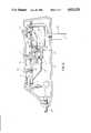
- FIG. 3is a cross sectional view of a mechanical housing having means for checking the circuit
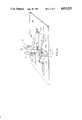
- FIG. 4shows a low cost way of manufacturing the device of FIG. 3.
- FIG. 1shows a prior art appliance power cord 20 having a standard commercial power line 22 connected to one end and a motor 24 connected to the other end, with an on/off switch 26 coupled to energize the motor.
- a solenoid coil 28is coupled across the line, in series with an electronic switch 30, here an SCR.
- the gate of the SCR 30is connected to the housing, frame or another potential point on motor 24. Normally, this housing, frame, or potential point is insulated from the power line and thus has no potential thereon.
- the SCRswitches on and energizes the solenoid 28.
- the solenoidoperates a set of contacts 32, 34 which open the power cord and remove the A.C. source 22 from the line 20.
- the prior art SCR 30is polarized so that, in the convention of current from plus to minus, the solenoid 28 is energized only when the upper end 36 of its coil is positive and the lower end is negative. Also, a firing pulse applied to the gate G of SCR 30 must have the proper polarity before the SCR 30 switches on. Accordingly, the assumption is that the house wiring 22 is properly polarized with the neutral or white wire connected to the terminal 38. If the house is improperly wired or if the wall plug of the appliance is reversed so that the neutral or white wire is connected at 36, and a hot wire is under water, but water does not reach the switch 26, and switch 26 is open, the potential appearing at G does not have the polarity which fires the SCR 30. If so, the electronic switch 30 is not operated. There may be other ways in which the circuit of FIG. 1 could malfunction.
- the inventive circuit of FIG. 2interrupts power regardless of whether the house is wired properly or whether the plug is correctly inserted into a wall outlet, with proper polarity.
- the circuit of FIG. 2does not depend upon the presence of a proper plumbing ground.
- the power cord 20 of FIG. 2has A.C. power 22 on one end and a motor 24 on the other end, with an on/off switch at 26.
- Two oppositely poled electronic switches (here SCRs) 40, 42are coupled to opposite sides 36, 38 of the power line 22, in order to insure that one switch is poled to conduct regardless of the proper or improper house wiring or plug orientation.
- the solenoid coil 28is isolated between two oppositely poled, steering diodes 44, 46. From an inspection of FIG. 2, it is seen that there are two circuits for operating the solenoid, one circuit being from A.C. power line 36 through diode 44, solenoid coil 28, and SCR 42 to A.C. power line 38.
- the other solenoid operating circuitis from A.C. power line 38 through diode 46, solenoid coil 28 and SCR 40 to the A.C. power line 36.
- the sensing or gating circuit 74extends from any suitable sensing point through current limiting resistor 48 and either steering diode 50 to the gate G of SCR 42 or steering diode 52 to the gate G of SCR 40.
- the effective one of those circuitsdepends upon which one of the power line wires 36, 38 is hot and which is neutral.
- the resistor 48 and one of the resistors 54 or 56form a voltage divider for setting the voltage level of the firing pulse applied to an SCR gate electrode G.
- the voltage level of the firing pulseshould have the lowest possible potential consistent with reliably firing an SCR.
- the capacitors 58, 60provide a high frequency bypass in order to prevent the SCR from firing in response to transients such as wild voltage spikes.
- Voltage limiting means in the form of MOV 62is connected across line 36, 38 to limit the voltage appearing across the SCR's 40, 42.
- a MOVis similar to two back to back zener diodes. At some maximum voltage, they conduct, thereby limiting the voltage of any wild spikes appearing on the line.
- Two push-to-operate switches 64, 66connect the sensing or gating circuit 74 to opposite sides of the line. An operation of these switches should turn on an SCR 44, 46 by simulating a fault. Thus, switches 64, 66 provide a test operations to insure that the circuit is in a proper working order.
- the reset latch contactsare closed by pushing a spring loaded push button 72.
- the lines 36, 38connect the motor 24 directly to the AC power source 22 via power cord 20. As long as there is no fault, the appliance operates as if the inventive circuit does not exist.
- the sensing or gating circuit 74also has a potential on it. Thus, a firing potential appears on sensing or gating circuit 74, and is applied to the SCR's 40, 42, gate electrodes via diodes 50, 52. If the wire 36 is hot and the wire 38 is at neutral potential, SCR 42 fires and a sustaining current flows from hot wire 36 through steering diode 44, solenoid 28, and SCR 42 to neutral.
- the componentshad approximately the following values:
- the diodes 44, 46, 50, 52may be any device which blocks the pertinent voltage in one polarity direction and conducts in the other direction.
- Capacitors 58, 60may be about 0.15 to 0.47 Fd, to provide a small delay to prevent a false firing of the SCRs from transients, while still firing them at a high speed to prevent shock hazards.
- Resistors 54, 56may be about 300-330 ohms.
- Resistor 48may be about 15-24 K ohms (Resistor 48 limits current on sensor wire 74 to about 7-10 milliamps).
- FIG. 3shows the mechanical aspect of the invention as a power cord 20 leading from an appliance to a wall plug 80 having a pair of terminals 82 for plugging into a wall outlet, or the like.
- the plug 80may be enclosed by a unitary molded rubber housing 84 or a two piece plastic housing which is held together by one or more bolts.
- FIG. 3is a side view and FIG. 4 is a perspective view of substantially the structure.
- a vertical spring and guide 97is integrally molded with or cemented on base plate. Two vertical windows W1, W2 are formed in the spring and guide 97 in order to protect the springs while enabling them to function properly.
- a latch plate 96controlled by an armature 98 on the solenoid 28.
- the two sets of springs 90a, 90b and 95a, 95bare treated as if they were one.
- Dependent from chassis 86is leaf spring 90 leading to a set of contacts 92, 94 through which the electrical power is transmitted to the appliance.
- Contacts 92, 94represent both of the contacts 68, 70 in FIG. 2. If these contacts are opened, all power is removed from the appliance.
- the second contacts 92is mounted on an end of leaf spring 95.
- the leaf springs 90, 95bias the contacts 92, 94 to an open position unless they are positively held closed by a latch 96.
- the solenoid winding at 28is the same as the winding 28 that is shown in FIG. 2. Therefore, if either of the SCR's 40, 42 conducts, the solenoid 28 is energized to attract a plunger or armature 98.
- This armatureis connected to the latch plate 96, having an end anchored at 100 to the chassis 86 and a hinge at point 102.
- the latch plate 96is withdrawn in direction C. This releases a hold down plate 104.
- the bias in spring 95snaps it upwardly to open contacts 92, 94 and to elevate a reset button 72.
- solenoid 28is deenergized, as by pulling terminals 82 of plug 80 from a wall outlet, armature 98 is released to return latch 96 under the urging of its spring bias in direction D, to the position shown in FIGS. 3, 4.
- the reset push button 72may be pushed.
- the shapes of the latch 96 and hold down plate 104cooperate to hold the contacts 92, 94 in a closed position.
- the neon bulb 110is an optional feature connected across the power line in order to indicate when power is applied to the appliance.
- the circuit to neon bulb 110, contacts 92, 94 and solenoid 28is completed at spade terminals 112.
- a pair of test buttons 114are provided for momentarily closing the contacts 64, 66 (FIG. 2). Resistors 65, 65 are provided to prevent a short circuit if both test buttons A and B are pushed simultaneously.
- a rocking switch 67may be provided to rock on pivot 69. If rocker switch 67 is pushed on the top (as viewed in FIG. 2A), only the switch A is closed to test the circuit with respect a potential on wire 36, switch B being unoperated. If rocker switch 67 is pushed on the bottom, only switch B may be closed to test the circuit with respect to a potential on wire 38. Since it is mechanically impossible to simultaneously close both switches A and B, there is no way for a short circuit to be applied across the wires 36, 38.
- the immersion detectorcuts off the power regardless of whether the house is properly wired, whether plastic plumbing, a marbled top, etc. insulate the sink or tub from a plumbing and regardless of whether the power switch 26 is opened or closed.
- the circuitdoes not respond to transients such as the wild voltage spikes that may appear on a commerical power line and yet does respond fast enough to protect an individual.
Landscapes
- Physics & Mathematics (AREA)
- Fluid Mechanics (AREA)
- Details Of Connecting Devices For Male And Female Coupling (AREA)
Abstract
Description
Claims (17)
Priority Applications (2)
| Application Number | Priority Date | Filing Date | Title |
|---|---|---|---|
| US07/141,928US4823225A (en) | 1987-08-18 | 1988-01-06 | Bipolar immersion detection circuit interrupter |
| US07/209,920US4851951A (en) | 1988-01-06 | 1988-06-22 | Non-defeatable safety mechanical actuators for appliances |
Applications Claiming Priority (2)
| Application Number | Priority Date | Filing Date | Title |
|---|---|---|---|
| US8690487A | 1987-08-18 | 1987-08-18 | |
| US07/141,928US4823225A (en) | 1987-08-18 | 1988-01-06 | Bipolar immersion detection circuit interrupter |
Related Parent Applications (1)
| Application Number | Title | Priority Date | Filing Date |
|---|---|---|---|
| US8690487AContinuation-In-Part | 1987-08-18 | 1987-08-18 |
Related Child Applications (1)
| Application Number | Title | Priority Date | Filing Date |
|---|---|---|---|
| US07/209,920Continuation-In-PartUS4851951A (en) | 1988-01-06 | 1988-06-22 | Non-defeatable safety mechanical actuators for appliances |
Publications (1)
| Publication Number | Publication Date |
|---|---|
| US4823225Atrue US4823225A (en) | 1989-04-18 |
Family
ID=26775285
Family Applications (1)
| Application Number | Title | Priority Date | Filing Date |
|---|---|---|---|
| US07/141,928Expired - LifetimeUS4823225A (en) | 1987-08-18 | 1988-01-06 | Bipolar immersion detection circuit interrupter |
Country Status (1)
| Country | Link |
|---|---|
| US (1) | US4823225A (en) |
Cited By (12)
| Publication number | Priority date | Publication date | Assignee | Title |
|---|---|---|---|---|
| US4967308A (en)* | 1989-02-13 | 1990-10-30 | Milton Morse | Enhanced safety device for an electrical appliance |
| AU714211B2 (en)* | 1995-09-08 | 1999-12-23 | Technology Research Corporation | Electrical system with arc protection |
| US6215378B1 (en) | 2000-01-25 | 2001-04-10 | Eaton Corporation | Circuit breaker with dual function test button remote from test circuit |
| US6285534B1 (en) | 2000-01-25 | 2001-09-04 | Eaton Corporation | Circuit breaker with common test button for separate testing of ground fault and ACR fault function |
| AU739122B2 (en)* | 1998-04-29 | 2001-10-04 | Eaton Corporation | Circuit breaker with common test button for ground fault and arc fault circuit |
| US6340926B1 (en)* | 1999-12-22 | 2002-01-22 | Defond Manufacturing Limited | Power plug with circuit breaker |
| RU2222090C1 (en)* | 2002-05-13 | 2004-01-20 | Бабушкин Владимир Петрович | Storage battery charging device |
| US20040228048A1 (en)* | 2002-03-27 | 2004-11-18 | Aromin Victor V. | Fireguard circuit |
| US20090034142A1 (en)* | 2007-07-31 | 2009-02-05 | Canon Kabushiki Kaisha | Circuit and heating apparatus |
| US7633399B2 (en) | 2007-02-27 | 2009-12-15 | Eaton Corporation | Configurable arc fault or ground fault circuit interrupter and method |
| US20100134932A1 (en)* | 1998-08-24 | 2010-06-03 | Leviton Manufacturing Company, Inc. | Circuit interrupting device with reset lockout and reverse wiring protection and method of manufacture |
| US20220311350A1 (en)* | 2020-04-28 | 2022-09-29 | Amber Solutions, Inc | TWO-WIRE Electronic switch and Dimmer |
Citations (14)
| Publication number | Priority date | Publication date | Assignee | Title |
|---|---|---|---|---|
| US3277407A (en)* | 1964-03-16 | 1966-10-04 | Terasaki Denki Sangyo Kk | Circuit interrupter |
| US3493815A (en)* | 1967-07-19 | 1970-02-03 | Gen Electric | Electric protective system |
| US3558988A (en)* | 1969-04-23 | 1971-01-26 | Ellenberger & Poensgen | Pushbutton-operated overload circuit breaker |
| US3813579A (en)* | 1970-11-09 | 1974-05-28 | Rucker Co | Electric receptacle assembly with ground fault protection |
| US4001647A (en)* | 1975-10-22 | 1977-01-04 | General Electric Company | Ground fault receptacle with unitary support of gfci module and switching mechanism |
| US4270158A (en)* | 1977-11-03 | 1981-05-26 | Antonino Ravida | System of protection against short circuits and fulminations |
| US4282500A (en)* | 1978-07-03 | 1981-08-04 | Merlin Gerin | Ground fault circuit interrupting device |
| US4412193A (en)* | 1978-09-07 | 1983-10-25 | Leviton Manufacturing Company, Inc. | Resettable circuit breaker for use in ground fault circuit interrupters and the like |
| US4464582A (en)* | 1982-10-12 | 1984-08-07 | Tsunehide Aragaki | Water-safe hair dryer circuit |
| US4568997A (en)* | 1978-09-07 | 1986-02-04 | Leviton Manufacturing Company, Inc. | Resettable circuit breaker for use in ground fault circuit interrupters and the like |
| US4589047A (en)* | 1982-03-06 | 1986-05-13 | Gaues Harry | Protective mechanism in electrically operated devices |
| US4595894A (en)* | 1983-12-05 | 1986-06-17 | Leviton Manufacturing Co., Inc. | Ground fault circuit interrupting system |
| CA1213665A (en)* | 1983-12-05 | 1986-11-04 | Bernard Gershen | Shock hazard protection system |
| US4751603A (en)* | 1986-07-07 | 1988-06-14 | Simatelex Manufactory Company Limited | Safety devices |
- 1988
- 1988-01-06USUS07/141,928patent/US4823225A/ennot_activeExpired - Lifetime
Patent Citations (15)
| Publication number | Priority date | Publication date | Assignee | Title |
|---|---|---|---|---|
| US3277407A (en)* | 1964-03-16 | 1966-10-04 | Terasaki Denki Sangyo Kk | Circuit interrupter |
| US3493815A (en)* | 1967-07-19 | 1970-02-03 | Gen Electric | Electric protective system |
| US3558988A (en)* | 1969-04-23 | 1971-01-26 | Ellenberger & Poensgen | Pushbutton-operated overload circuit breaker |
| US3813579A (en)* | 1970-11-09 | 1974-05-28 | Rucker Co | Electric receptacle assembly with ground fault protection |
| US4001647A (en)* | 1975-10-22 | 1977-01-04 | General Electric Company | Ground fault receptacle with unitary support of gfci module and switching mechanism |
| US4270158A (en)* | 1977-11-03 | 1981-05-26 | Antonino Ravida | System of protection against short circuits and fulminations |
| US4282500A (en)* | 1978-07-03 | 1981-08-04 | Merlin Gerin | Ground fault circuit interrupting device |
| US4412193A (en)* | 1978-09-07 | 1983-10-25 | Leviton Manufacturing Company, Inc. | Resettable circuit breaker for use in ground fault circuit interrupters and the like |
| US4568997A (en)* | 1978-09-07 | 1986-02-04 | Leviton Manufacturing Company, Inc. | Resettable circuit breaker for use in ground fault circuit interrupters and the like |
| US4589047A (en)* | 1982-03-06 | 1986-05-13 | Gaues Harry | Protective mechanism in electrically operated devices |
| US4464582A (en)* | 1982-10-12 | 1984-08-07 | Tsunehide Aragaki | Water-safe hair dryer circuit |
| US4595894A (en)* | 1983-12-05 | 1986-06-17 | Leviton Manufacturing Co., Inc. | Ground fault circuit interrupting system |
| CA1213665A (en)* | 1983-12-05 | 1986-11-04 | Bernard Gershen | Shock hazard protection system |
| CA1218445A (en)* | 1983-12-05 | 1987-02-24 | Richard C. Doyle | Shock hazard protection system |
| US4751603A (en)* | 1986-07-07 | 1988-06-14 | Simatelex Manufactory Company Limited | Safety devices |
Cited By (18)
| Publication number | Priority date | Publication date | Assignee | Title |
|---|---|---|---|---|
| US4967308A (en)* | 1989-02-13 | 1990-10-30 | Milton Morse | Enhanced safety device for an electrical appliance |
| US6292337B1 (en)* | 1993-08-05 | 2001-09-18 | Technology Research Corporation | Electrical system with arc protection |
| AU714211B2 (en)* | 1995-09-08 | 1999-12-23 | Technology Research Corporation | Electrical system with arc protection |
| AU739122B2 (en)* | 1998-04-29 | 2001-10-04 | Eaton Corporation | Circuit breaker with common test button for ground fault and arc fault circuit |
| US6392513B1 (en)* | 1998-04-29 | 2002-05-21 | Eaton Corporation | Circuit breaker with common test button for ground fault and arc fault circuit |
| US20100134932A1 (en)* | 1998-08-24 | 2010-06-03 | Leviton Manufacturing Company, Inc. | Circuit interrupting device with reset lockout and reverse wiring protection and method of manufacture |
| US8054595B2 (en) | 1998-08-24 | 2011-11-08 | Leviton Manufacturing Co., Inc. | Circuit interrupting device with reset lockout |
| US8130480B2 (en) | 1998-08-24 | 2012-03-06 | Leviton Manufactuing Co., Inc. | Circuit interrupting device with reset lockout |
| US6340926B1 (en)* | 1999-12-22 | 2002-01-22 | Defond Manufacturing Limited | Power plug with circuit breaker |
| US6285534B1 (en) | 2000-01-25 | 2001-09-04 | Eaton Corporation | Circuit breaker with common test button for separate testing of ground fault and ACR fault function |
| US6215378B1 (en) | 2000-01-25 | 2001-04-10 | Eaton Corporation | Circuit breaker with dual function test button remote from test circuit |
| US20040228048A1 (en)* | 2002-03-27 | 2004-11-18 | Aromin Victor V. | Fireguard circuit |
| RU2222090C1 (en)* | 2002-05-13 | 2004-01-20 | Бабушкин Владимир Петрович | Storage battery charging device |
| US7633399B2 (en) | 2007-02-27 | 2009-12-15 | Eaton Corporation | Configurable arc fault or ground fault circuit interrupter and method |
| US20090034142A1 (en)* | 2007-07-31 | 2009-02-05 | Canon Kabushiki Kaisha | Circuit and heating apparatus |
| US8610315B2 (en)* | 2007-07-31 | 2013-12-17 | Canon Kabushiki Kaisha | Circuit and heating apparatus that completely cuts power to a supply circuit due to blowout of a fuse on a single supply line |
| US20220311350A1 (en)* | 2020-04-28 | 2022-09-29 | Amber Solutions, Inc | TWO-WIRE Electronic switch and Dimmer |
| US11870364B2 (en)* | 2020-04-28 | 2024-01-09 | Amber Solutions, Inc. | Two-wire electronic switch and dimmer |
Similar Documents
| Publication | Publication Date | Title |
|---|---|---|
| US4823225A (en) | Bipolar immersion detection circuit interrupter | |
| US7428132B1 (en) | Protection device with lockout test | |
| US6954125B2 (en) | Ground fault circuit interrupter with reverse wiring protection | |
| US6946935B2 (en) | Ground fault circuit interrupter with reverse wiring protection | |
| US7751162B1 (en) | Protective device with miswire protection | |
| US7915899B2 (en) | Electrical safety devices and systems for use with electrical wiring, and methods for using same | |
| US4967308A (en) | Enhanced safety device for an electrical appliance | |
| US4647120A (en) | Electrical safety plug connection | |
| US8477466B1 (en) | Protective device with separate end-of-life trip mechanism | |
| MX2015000608A (en) | Self-test gfci device with dual solenoid coil electric control. | |
| US20040070895A1 (en) | Leakage current detection interrupter extension cord with cord diagnostics and/or inadvertent ground-to-neutral detection | |
| MX2013002907A (en) | Reinstallable circuit interrupting device with vibration resistant miswire protection. | |
| US4791519A (en) | Shock protective circuit with electrical latch for small appliances | |
| CN202353192U (en) | Wiring protecting device for power distribution system | |
| US4954922A (en) | Protective system for portable electrically powered apparatus | |
| US20050110501A1 (en) | Electrical circuit test apparatus | |
| US4028594A (en) | Safety circuit for electrical equipment | |
| DE3702970C2 (en) | ||
| EP0235859B1 (en) | Shock protective circuit with mechanical latch for small appliances | |
| EP0961129B1 (en) | Test circuit with time-limited fault current for a protection device | |
| US20130170083A1 (en) | Power-on reset gfci | |
| CN221842327U (en) | Power line leakage detection and protection device, electrical connection equipment and electrical device | |
| WO1989005050A1 (en) | Protective device for electrical mains appliances, in particular manual appliances | |
| JPH10117429A (en) | Non-tracking outlet | |
| SU1171897A1 (en) | Device for protection of person against electric current stroke in system with solidly earthed neutral |
Legal Events
| Date | Code | Title | Description |
|---|---|---|---|
| AS | Assignment | Owner name:ASSOCIATED MILLS INC., 111 NORTH CANAL STREET CHIC Free format text:ASSIGNMENT OF ASSIGNORS INTEREST.;ASSIGNORS:FOSTER, ROBERT W.;KEMPIAK, DONALD J.;REEL/FRAME:004819/0031 Effective date:19871230 Owner name:ASSOCIATED MILLS INC.,ILLINOIS Free format text:ASSIGNMENT OF ASSIGNORS INTEREST;ASSIGNORS:FOSTER, ROBERT W.;KEMPIAK, DONALD J.;REEL/FRAME:004819/0031 Effective date:19871230 | |
| STCF | Information on status: patent grant | Free format text:PATENTED CASE | |
| AS | Assignment | Owner name:HARRIS TRUST AND SAVINGS BANK, A CORP. OF IL Free format text:SECURITY INTEREST;ASSIGNOR:ASSOCIATED MILLS, INC., A CORP. OF IL;REEL/FRAME:005866/0178 Effective date:19910927 Owner name:ODYSSEY INVESTORS, INC.,, NEW YORK Free format text:SECURITY INTEREST;ASSIGNOR:ASSOCIATED MILLS, INC., A CORP. OF IL;REEL/FRAME:005866/0187 Effective date:19910927 Owner name:FIRST NATIONAL BANK OF CHICAGO, THE Free format text:SECURITY INTEREST;ASSIGNOR:ASSOCIATED MILLS, INC., A CORP. OF IL;REEL/FRAME:005866/0178 Effective date:19910927 | |
| FEPP | Fee payment procedure | Free format text:PAYOR NUMBER ASSIGNED (ORIGINAL EVENT CODE: ASPN); ENTITY STATUS OF PATENT OWNER: LARGE ENTITY | |
| AS | Assignment | Owner name:POLLENEX CORPORATION Free format text:CHANGE OF NAME;ASSIGNOR:ASSOCIATED MILLS, INC., A CORP. OF IL;REEL/FRAME:006144/0014 Effective date:19920131 | |
| FPAY | Fee payment | Year of fee payment:4 | |
| AS | Assignment | Owner name:POLLENEX CORPORATION A MISSOURI CORPORATION Free format text:ASSIGNMENT OF ASSIGNORS INTEREST;ASSIGNOR:POLLENEX CORPORATION, AN ILLINOIS CORPORATION (FORMERLY KNOWN AS ASSOCIATED MILLS, INC.);REEL/FRAME:006631/0318 Effective date:19930430 Owner name:POLLENEX CORPORATION, A MISSOURI CORPORATION Free format text:RELEASE BY SECURED PARTY;ASSIGNOR:HARRIS TRUST AND SAVINGS BANK;REEL/FRAME:006631/0305 Effective date:19930430 Owner name:POLLENEX CORPORATION, A MISSOURI CORPORATION Free format text:RELEASE BY SECURED PARTY;ASSIGNOR:ODYSSEY INVESTORS, INC.;REEL/FRAME:006631/0310 Effective date:19930430 | |
| REMI | Maintenance fee reminder mailed | ||
| FEPP | Fee payment procedure | Free format text:PAYER NUMBER DE-ASSIGNED (ORIGINAL EVENT CODE: RMPN); ENTITY STATUS OF PATENT OWNER: LARGE ENTITY Free format text:PAYOR NUMBER ASSIGNED (ORIGINAL EVENT CODE: ASPN); ENTITY STATUS OF PATENT OWNER: LARGE ENTITY Free format text:PAT HLDR NO LONGER CLAIMS SMALL ENT STAT AS INDIV INVENTOR (ORIGINAL EVENT CODE: LSM1); ENTITY STATUS OF PATENT OWNER: LARGE ENTITY | |
| FPAY | Fee payment | Year of fee payment:8 | |
| SULP | Surcharge for late payment | ||
| AS | Assignment | Owner name:RIVAL COMPANY, THE, MISSOURI Free format text:ASSIGNMENT OF ASSIGNORS INTEREST;ASSIGNOR:POLLENEX CORPORATION;REEL/FRAME:009893/0334 Effective date:19980109 | |
| AS | Assignment | Owner name:BANKBOSTON, N.A., AS AGENT, MASSACHUSETTS Free format text:PATENT COLLATERAL ASSIGNMENT AND SECURITY AGREEMENT;ASSIGNOR:RIVAL COMPANY, THE;REEL/FRAME:009968/0802 Effective date:19990205 | |
| REMI | Maintenance fee reminder mailed | ||
| FPAY | Fee payment | Year of fee payment:12 | |
| SULP | Surcharge for late payment | Year of fee payment:11 | |
| AS | Assignment | Owner name:THE RIVAL COMPANY, MASSACHUSETTS Free format text:RELEASE OF SECURITY INTEREST RECORDED AT REEL 009968 FRAME 0802;ASSIGNOR:FLEET NATIONAL BANK;REEL/FRAME:015065/0091 Effective date:20040506 | |
| AS | Assignment | Owner name:THE HOLMES GROUP, INC., MASSACHUSETTS Free format text:MERGER;ASSIGNOR:THE RIVAL COMPANY;REEL/FRAME:015065/0519 Effective date:20040504 Owner name:GENERAL ELECTRIC CAPITAL CORPORATION, AS COLLATERA Free format text:SECURITY AGREEMENT;ASSIGNOR:HOLMES GROUP, INC. THE;REEL/FRAME:015065/0681 Effective date:20040506 |