US4823149A - Ink jet apparatus employing plate-like structure - Google Patents
Ink jet apparatus employing plate-like structureDownload PDFInfo
- Publication number
- US4823149A US4823149AUS07/023,706US2370687AUS4823149AUS 4823149 AUS4823149 AUS 4823149AUS 2370687 AUS2370687 AUS 2370687AUS 4823149 AUS4823149 AUS 4823149A
- Authority
- US
- United States
- Prior art keywords
- ink jet
- chamber
- jet apparatus
- orifice
- plate
- Prior art date
- Legal status (The legal status is an assumption and is not a legal conclusion. Google has not performed a legal analysis and makes no representation as to the accuracy of the status listed.)
- Expired - Fee Related
Links
Images

Classifications
- B—PERFORMING OPERATIONS; TRANSPORTING
- B41—PRINTING; LINING MACHINES; TYPEWRITERS; STAMPS
- B41J—TYPEWRITERS; SELECTIVE PRINTING MECHANISMS, i.e. MECHANISMS PRINTING OTHERWISE THAN FROM A FORME; CORRECTION OF TYPOGRAPHICAL ERRORS
- B41J2/00—Typewriters or selective printing mechanisms characterised by the printing or marking process for which they are designed
- B41J2/005—Typewriters or selective printing mechanisms characterised by the printing or marking process for which they are designed characterised by bringing liquid or particles selectively into contact with a printing material
- B41J2/01—Ink jet
- B41J2/135—Nozzles
- B41J2/145—Arrangement thereof
- B41J2/15—Arrangement thereof for serial printing
Definitions
- This inventionrelates generally to impulse or demand ink jets, and more particularly, to such ink jets wherein a piezoelectric transducer has an axis of elongation so as to expand and contract along the axis of elongation, thereby changing the volume of ink in an ink jet chamber including an orifice.
- a preferred embodimentcomprises an ink jet chamber including an orifice with an axis and an elongated transducer means coupled to the chamber for changing the volume of the chamber in response to the state of energization of the transducer means by expanding and contracting along the axis of elongation.
- the apparatuscomprises coupling means in communication with the transducer means.
- the coupling meanscomprises a drive portion juxtaposed to the transducer means in the ink jet chamber and a supporting portion, including at least one strut, connected to a support means.
- the strutextends from the drive portion in a direction substantially transverse to the axis of elongation and is attached to the support means.
- the strutincludes an area of relief in advance thereof toward the chamber and an area of relief behind and away from the chamber so as to permit the strut to flex toward the chamber and away from the chamber in the direction of the axis of the orifice, thereby permitting the drive portion to move toward the chamber and away from the chamber.
- the apparatuscomprises more than one strut.
- the strutsextend in opposite directions from the drive portion toward the support means. Additional struts may be spaced along the drive portion in the direction of the axis of the orifice.
- the ink jet chamber, the coupling means and the support meansare all formed from the same integral member. This permits a plate-like structural approach to the ink jet, even with the use of the elongated transducer. Additional plates on opposite sides of the plate, including the chamber, are employed to close the fluidic channels including the chamber.
- the apparatusmay comprise an inlet manifold, a vent and/or restricted passageways so as to provide a diode effect in the fluidic channels.
- the manifold, the vent and the restricted passagewaysmay all be formed from the same plate-like member which forms the chamber.
- the chamberis characterized by a maximum dimension transverse to the axis of the orifice which is substantially greater than the minimum dimension of the chamber transverse to the axis of the orifice.
- the maximum dimensionis at least ten (10) times greater than the minimum dimension.
- the plate coupling portion between the transducer and the chamberextends further toward the transducer than the support means.
- the ink jet apparatuscomprises a plurality of plate-like members wherein non-contiguous plate-like members contain the chambers and orifices of the ink jets.
- the orifices in the non-contiguous platesmay be arranged so as to achieve a substantially linear array extending from plate to plate in the apparatus.
- each plate containing an ink jet chamber and orificemay contain a plurality of spaced chambers and orifices so as to achieve a plurality of linear arrays. In such an apparatus, different colored inks may be utilized in each linear array.
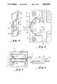
- FIG. 1is a perspective view of a single plate-like structure partially forming an ink jet apparatus representing a preferred embodiment of the invention
- FIG. 2is an exploded view of a plurality of the plate-like structure shown in FIG. 1 with spacer plates there between;
- FIG. 3is a perspective view of the assembled apparatus of FIG. 2;
- FIG. 4is a partial and enlarged perspective view of the chamber shown in FIG. 1;
- FIG. 5is a partial and enlarged plan view of a plate-like structure in an embodiment modified from that shown in FIGS. 1 through 4;
- FIG. 6is a perspective view showing a plurality of linear arrays achieved from a plurality of plate-like structures of the type shown in FIGS. 1 through 5;
- FIG. 7is an alternative embodiment of the invention wherein the plate-like structure forming the chamber forms part of the transducer.
- an impulse ink jet apparatusformed from an assembly of plates comprising individual, non-contiguous plates 10 sandwiched between separating plates 12.
- Each of the plates 10comprises and forms a chamber 14 as shown in FIG. 1 which includes an orifice 16, while the separating plates 12 form inter-channel septa for reducing fluidic cross-talk between adjacent orifices 16.
- the plate 10further comprises a coupling means or drive portion 18 at the rear of the chamber juxtaposed to the orifice 16 and coupled to a transducer 20.
- the coupling means 18is supported by the support means 22 by struts 24.
- the chamber 14, the coupling means or foot 18, the support means 22 and the struts 24all are formed from a single plate. This facilitates the economical manufacture of the ink jet apparatus shown in FIGS. 1 through 3 in accordance with one important aspect of the invention.
- the struts 24permit sufficient movement of the foot 18 in response to energization of the transducer 20 along its axis of elongation in each direction generally toward and away from the chamber 14 so as to permit the volume of the chamber 14 to be expanded and contracted for purposes of ejecting droplets of ink from the orifice 16.
- an area of relief 26is provided in front of each of the struts 24.
- an area of relief 28is provided behind each of the struts 24.
- a plurality of struts 24are utilized.
- the struts 24extend transversely on opposite sides of the foot 18. It is also preferred to have a plurality of struts along the axis of movement of the transducer 20 and the foot 18 so as to optimize support of the foot 18.
- the chamber 14, the foot 18, the support portion 22 and the struts 24are all integrally formed from the same plate. It is also preferable to form an input manifold 30 with a passageway 32 and a vent manifold 34 with a passageway 36 from the same plate. Note that the areas of relief 26 actually form and are coincident with the passageways 32 and 36.
- the manifold 30 and 34are formed by corresponding orifices in the septa, adjacent thereto so as to form canals whose axes of elongation are perpendicular to the plan of the foot 18. This allows ink to reach the channels from a common source of ink located externally from the channel structure and connected there by tubes 42 (FIG. 3).
- the transducer 20expands and contracts along its axis of elongation which is coincident with the axis of the orifice 16. This motion of the transducer, which in turn creates motion of the foot 18, is achieved by applying the field transverse to the transducer 20 in accordance with the disclosure of the aforesaid U.S. Pat. No. 4,459,601.
- FIGS. 2 and 3it will be appreciated that the various plates 10 and 12 are sandwiched together to form the assembly 38 shown in FIG. 3. These plates are clamped together by clamping end plates 40.
- each of the input manifold openings 30 and vent manifolds 34are aligned so as to permit each of the chambers 14 to be supplied by ink by means of tubes 42 shown in FIG. 3.
- This alignmentis achieved by use of locator pins 44 which are inserted through openings 46 shown in FIG. 1.
- locator pins 44which are inserted through openings 46 shown in FIG. 1.
- the chamber 14which is achieved with the apparatus shown in FIG. 4 has substantially greater dimensions in one direction than in another. More specifically, the length of the chamber as depicted by the arrow 50 in FIG. 4 is substantially greater than the width of the chamber as depicted by the arrows 52. In other words, the maximum dimension of the chamber 14 in a direction transverse to the axis of the orifice 16 (i.e., "length") is substantially greater than the minimum dimension of the chamber 14 in a direction transverse to the axis of the orifice 16 (i.e., "width"). Preferably, the ratio of this length to the width is at least 10:1, with 18:1 being considered optimum.
- the end of the foot 18, which is juxtaposed to the orifice 16comprises a concave surface 54. Note the arrow 56 in FIGS. 1 and 4 which depict the motion of the foot 18.
- FIG. 5An alternative embodiment of the fluidic section of the apparatus shown in FIGS. 1 through 4 is depicted in FIG. 5.
- the foot 118comprises a somewhat different shape to achieve a plurality of restrictors which are dynamically positioned so as to function as valves or fluidic diodes. More specifically, points 120 and 121 are juxtaposed respectively to corners 123 and 125 in the plate 110. As the foot 118 moves in the direction depicted by the arrows 156, the flow of ink, depicted by arrows 160, is alternately restricted and facilitated at the locations of the points 120 and 121. As a result, a dynamic restrictor is achieved for controlling the flow of ink into the chamber 114 and the ejection of droplets 117 through the orifice 116.
- each of the plates 10 or 110included a single chamber and associated coupling means or foot 18 or 118 for its associated transducer. It is, of course, possible to provide a plurality of chambers, coupling means and transducers for each plate.
- FIG. 6shows such an embodiment where four linear arrays of orifices 216 are displaced along a direction of travel 248. It will be appreciated that each of the orifices of the arrays 216 is in a single plate with each plate having four such orifices. With this embodiment, it is possible to utilize different colored inks in each linear array 216 so as to achieve, for example, a four color printhead. This, of course, requires separate input and vent manifolds for each of the linear arrays 216. Otherwise, the apparatus shown in FIG. 6 is substantially identical to that shown in FIGS. 1 through 3.
- FIG. 7depicts an embodiment of the invention wherein even the transducer has been integrated into a single plate.
- the accompanying means 18is sandwiched between a strip of piezoelectric material 62 and another strip of piezoelectric material on the opposite side of the foot 18 which is not shown so as to form a trimorph.
- the strip 62 together with that not shownare coupled to a source of electric driving pulses as schematically depicted.
- the net resultis a trimorph which moves the foot 18 toward and away from the orifice 16 as discussed with respect to the embodiment of FIGS. 1 through 3.
Landscapes
- Particle Formation And Scattering Control In Inkjet Printers (AREA)
Abstract
Description
Claims (21)
Priority Applications (1)
| Application Number | Priority Date | Filing Date | Title |
|---|---|---|---|
| US07/023,706US4823149A (en) | 1987-03-09 | 1987-03-09 | Ink jet apparatus employing plate-like structure |
Applications Claiming Priority (1)
| Application Number | Priority Date | Filing Date | Title |
|---|---|---|---|
| US07/023,706US4823149A (en) | 1987-03-09 | 1987-03-09 | Ink jet apparatus employing plate-like structure |
Publications (1)
| Publication Number | Publication Date |
|---|---|
| US4823149Atrue US4823149A (en) | 1989-04-18 |
Family
ID=21816745
Family Applications (1)
| Application Number | Title | Priority Date | Filing Date |
|---|---|---|---|
| US07/023,706Expired - Fee RelatedUS4823149A (en) | 1987-03-09 | 1987-03-09 | Ink jet apparatus employing plate-like structure |
Country Status (1)
| Country | Link |
|---|---|
| US (1) | US4823149A (en) |
Cited By (9)
| Publication number | Priority date | Publication date | Assignee | Title |
|---|---|---|---|---|
| US5126755A (en)* | 1991-03-26 | 1992-06-30 | Videojet Systems International, Inc. | Print head assembly for ink jet printer |
| US5165061A (en)* | 1989-12-08 | 1992-11-17 | Oce-Nederland B.V. | Stackable drop generator for an ink-jet printer |
| US6527369B1 (en) | 1995-10-25 | 2003-03-04 | Hewlett-Packard Company | Asymmetric printhead orifice |
| US6557974B1 (en) | 1995-10-25 | 2003-05-06 | Hewlett-Packard Company | Non-circular printhead orifice |
| US20050001886A1 (en)* | 2003-07-03 | 2005-01-06 | Scott Hock | Fluid ejection assembly |
| US20050206679A1 (en)* | 2003-07-03 | 2005-09-22 | Rio Rivas | Fluid ejection assembly |
| US20060238578A1 (en)* | 2005-04-26 | 2006-10-26 | Lebron Hector J | Fluid ejection assembly |
| US20060238577A1 (en)* | 2005-04-26 | 2006-10-26 | Hock Scott W | Fluid ejection assembly |
| US20080129798A1 (en)* | 2006-12-01 | 2008-06-05 | Samsung Electronics Co., Ltd. | Restrictors with structure to prevent back flow and inkjet head having the same |
Citations (6)
| Publication number | Priority date | Publication date | Assignee | Title |
|---|---|---|---|---|
| US4353078A (en)* | 1979-09-24 | 1982-10-05 | International Business Machines Corporation | Ink jet print head having dynamic impedance adjustment |
| US4385304A (en)* | 1979-07-09 | 1983-05-24 | Burroughs Corporation | Stacked drop generators for pulsed ink jet printing |
| US4387383A (en)* | 1981-11-12 | 1983-06-07 | Ncr Corporation | Multiple nozzle ink jet print head |
| US4446469A (en)* | 1982-03-31 | 1984-05-01 | Xerox Corporation | Ink jet printer array |
| US4459601A (en)* | 1981-01-30 | 1984-07-10 | Exxon Research And Engineering Co. | Ink jet method and apparatus |
| US4578686A (en)* | 1984-02-02 | 1986-03-25 | Siemens Aktiengesellschaft | Ink printhead |
- 1987
- 1987-03-09USUS07/023,706patent/US4823149A/ennot_activeExpired - Fee Related
Patent Citations (6)
| Publication number | Priority date | Publication date | Assignee | Title |
|---|---|---|---|---|
| US4385304A (en)* | 1979-07-09 | 1983-05-24 | Burroughs Corporation | Stacked drop generators for pulsed ink jet printing |
| US4353078A (en)* | 1979-09-24 | 1982-10-05 | International Business Machines Corporation | Ink jet print head having dynamic impedance adjustment |
| US4459601A (en)* | 1981-01-30 | 1984-07-10 | Exxon Research And Engineering Co. | Ink jet method and apparatus |
| US4387383A (en)* | 1981-11-12 | 1983-06-07 | Ncr Corporation | Multiple nozzle ink jet print head |
| US4446469A (en)* | 1982-03-31 | 1984-05-01 | Xerox Corporation | Ink jet printer array |
| US4578686A (en)* | 1984-02-02 | 1986-03-25 | Siemens Aktiengesellschaft | Ink printhead |
Non-Patent Citations (1)
| Title |
|---|
| Krause, K. A.; Focusing Ink Jet Head, IBM TDB, vol. 16, No. 4, Sep. 1973, p. 1168.* |
Cited By (15)
| Publication number | Priority date | Publication date | Assignee | Title |
|---|---|---|---|---|
| US5165061A (en)* | 1989-12-08 | 1992-11-17 | Oce-Nederland B.V. | Stackable drop generator for an ink-jet printer |
| US5126755A (en)* | 1991-03-26 | 1992-06-30 | Videojet Systems International, Inc. | Print head assembly for ink jet printer |
| AU641890B2 (en)* | 1991-03-26 | 1993-09-30 | Videojet Systems International, Inc. | Print head assembly for ink jet printer |
| US6527369B1 (en) | 1995-10-25 | 2003-03-04 | Hewlett-Packard Company | Asymmetric printhead orifice |
| US6557974B1 (en) | 1995-10-25 | 2003-05-06 | Hewlett-Packard Company | Non-circular printhead orifice |
| US6890067B2 (en)* | 2003-07-03 | 2005-05-10 | Hewlett-Packard Development Company, L.P. | Fluid ejection assembly |
| US20050001886A1 (en)* | 2003-07-03 | 2005-01-06 | Scott Hock | Fluid ejection assembly |
| US20050206679A1 (en)* | 2003-07-03 | 2005-09-22 | Rio Rivas | Fluid ejection assembly |
| US20060238578A1 (en)* | 2005-04-26 | 2006-10-26 | Lebron Hector J | Fluid ejection assembly |
| US20060238577A1 (en)* | 2005-04-26 | 2006-10-26 | Hock Scott W | Fluid ejection assembly |
| US7380914B2 (en) | 2005-04-26 | 2008-06-03 | Hewlett-Packard Development Company, L.P. | Fluid ejection assembly |
| US20080197108A1 (en)* | 2005-04-26 | 2008-08-21 | Lebron Hector Jose | Fluid Ejection Assembly |
| US7540593B2 (en) | 2005-04-26 | 2009-06-02 | Hewlett-Packard Development Company, L.P. | Fluid ejection assembly |
| US20080129798A1 (en)* | 2006-12-01 | 2008-06-05 | Samsung Electronics Co., Ltd. | Restrictors with structure to prevent back flow and inkjet head having the same |
| US7802874B2 (en)* | 2006-12-01 | 2010-09-28 | Samsung Electronics Co., Ltd | Restrictors with structure to prevent back flow and inkjet head having the same |
Similar Documents
| Publication | Publication Date | Title |
|---|---|---|
| US5677718A (en) | Drop-on-demand ink jet print head having improved purging performance | |
| EP0426473B1 (en) | Drop-on-demand ink jet print head | |
| US3988745A (en) | Printing ink supply device for ink jet printer | |
| US5489930A (en) | Ink jet head with internal filter | |
| EP0622210B1 (en) | Multiple-orifice drop-on-demand ink jet print head having improved purging and jetting performance | |
| US6502929B1 (en) | Laminated ink jet recording head having a plurality of actuator units | |
| US6179408B1 (en) | Apparatus for printing with ink jet chambers utilizing a plurality of orifices | |
| US4823149A (en) | Ink jet apparatus employing plate-like structure | |
| EP0661156A2 (en) | Ink jet recording head | |
| US4891654A (en) | Ink jet array | |
| EP0750987B1 (en) | Actuator for an ink jet print head | |
| US6050679A (en) | Ink jet printer transducer array with stacked or single flat plate element | |
| JPH07195685A (en) | Recording head for inkjet printer | |
| EP0260884B1 (en) | Print head for drop-on-demand ink jet printing apparatus | |
| EP1552932B1 (en) | Drop emitting device | |
| US6199970B1 (en) | Acoustic ink jet printhead design and method of operation utilizing ink cross-flow | |
| EP1552933B1 (en) | Drop emitting device | |
| EP1552931B1 (en) | Drop emitting apparatus | |
| JP3311514B2 (en) | Ink jet head and method of manufacturing the same | |
| EP1552930B1 (en) | Drop emitting device | |
| CA2313710C (en) | An acoustic ink jet printhead design and method of operation utilizing ink cross-flow | |
| US6874869B1 (en) | Inkjet printhead | |
| JP3675016B2 (en) | Inkjet head | |
| EP1552929A1 (en) | Drop emitting device | |
| US20050151785A1 (en) | Drop generating apparatus |
Legal Events
| Date | Code | Title | Description |
|---|---|---|---|
| AS | Assignment | Owner name:IMAGING SOLUTIONS, INC., A CORP. OF DE. Free format text:ASSIGNMENT OF ASSIGNORS INTEREST.;ASSIGNORS:MARTNER, JOHN G.;GARDNER, WILLIAM R.;MALTSEV, VIASHESLAV B.;REEL/FRAME:004677/0755;SIGNING DATES FROM 19870218 TO 19870303 | |
| AS | Assignment | Owner name:DATAPRODUCTS CORPORATION, A CORP. OF CA. Free format text:ASSIGNMENT OF ASSIGNORS INTEREST.;ASSIGNOR:IMAGING SOLUTIONS, INC;REEL/FRAME:004766/0581 Effective date:19870717 | |
| AS | Assignment | Owner name:HOWTEK, INC., 21 PARK AVENUE, HUDSON, NEW HAMPSHIR Free format text:LICENSE;ASSIGNOR:DATAPRODUCTS CORPORATION, A DE CORP.;REEL/FRAME:004815/0431 Effective date:19871130 | |
| FEPP | Fee payment procedure | Free format text:PAYOR NUMBER ASSIGNED (ORIGINAL EVENT CODE: ASPN); ENTITY STATUS OF PATENT OWNER: LARGE ENTITY | |
| FPAY | Fee payment | Year of fee payment:4 | |
| REMI | Maintenance fee reminder mailed | ||
| LAPS | Lapse for failure to pay maintenance fees | ||
| FP | Lapsed due to failure to pay maintenance fee | Effective date:19970423 | |
| STCH | Information on status: patent discontinuation | Free format text:PATENT EXPIRED DUE TO NONPAYMENT OF MAINTENANCE FEES UNDER 37 CFR 1.362 |