US4822144A - Electro-optic color display including luminescent layer and interference filter - Google Patents
Electro-optic color display including luminescent layer and interference filterDownload PDFInfo
- Publication number
- US4822144A US4822144AUS07/134,432US13443287AUS4822144AUS 4822144 AUS4822144 AUS 4822144AUS 13443287 AUS13443287 AUS 13443287AUS 4822144 AUS4822144 AUS 4822144A
- Authority
- US
- United States
- Prior art keywords
- radiation
- display device
- electro
- luminescent materials
- interference filter
- Prior art date
- Legal status (The legal status is an assumption and is not a legal conclusion. Google has not performed a legal analysis and makes no representation as to the accuracy of the status listed.)
- Expired - Fee Related
Links
- 230000005855radiationEffects0.000claimsabstractdescription52
- OAICVXFJPJFONN-UHFFFAOYSA-NPhosphorusChemical compound[P]OAICVXFJPJFONN-UHFFFAOYSA-N0.000claimsabstractdescription29
- 230000005540biological transmissionEffects0.000claimsabstractdescription5
- 239000000463materialSubstances0.000claimsdescription39
- 239000000758substrateSubstances0.000claimsdescription10
- VYPSYNLAJGMNEJ-UHFFFAOYSA-NSilicium dioxideChemical compoundO=[Si]=OVYPSYNLAJGMNEJ-UHFFFAOYSA-N0.000claimsdescription9
- 239000007788liquidSubstances0.000claimsdescription5
- 229910052814silicon oxideInorganic materials0.000claimsdescription5
- RVTZCBVAJQQJTK-UHFFFAOYSA-Noxygen(2-);zirconium(4+)Chemical compound[O-2].[O-2].[Zr+4]RVTZCBVAJQQJTK-UHFFFAOYSA-N0.000claimsdescription4
- 229910001928zirconium oxideInorganic materials0.000claimsdescription4
- 239000002178crystalline materialSubstances0.000claimsdescription3
- 229910052751metalInorganic materials0.000claimsdescription3
- 239000002184metalSubstances0.000claimsdescription3
- BPUBBGLMJRNUCC-UHFFFAOYSA-Noxygen(2-);tantalum(5+)Chemical compound[O-2].[O-2].[O-2].[O-2].[O-2].[Ta+5].[Ta+5]BPUBBGLMJRNUCC-UHFFFAOYSA-N0.000claimsdescription3
- GWEVSGVZZGPLCZ-UHFFFAOYSA-NTitan oxideChemical compoundO=[Ti]=OGWEVSGVZZGPLCZ-UHFFFAOYSA-N0.000claimsdescription2
- 239000003989dielectric materialSubstances0.000claimsdescription2
- CJNBYAVZURUTKZ-UHFFFAOYSA-Nhafnium(iv) oxideChemical compoundO=[Hf]=OCJNBYAVZURUTKZ-UHFFFAOYSA-N0.000claimsdescription2
- ORUIBWPALBXDOA-UHFFFAOYSA-Lmagnesium fluorideChemical compound[F-].[F-].[Mg+2]ORUIBWPALBXDOA-UHFFFAOYSA-L0.000claimsdescription2
- URLJKFSTXLNXLG-UHFFFAOYSA-Nniobium(5+);oxygen(2-)Chemical compound[O-2].[O-2].[O-2].[O-2].[O-2].[Nb+5].[Nb+5]URLJKFSTXLNXLG-UHFFFAOYSA-N0.000claimsdescription2
- 229910001936tantalum oxideInorganic materials0.000claims2
- 239000004973liquid crystal related substanceSubstances0.000description7
- 239000011521glassSubstances0.000description6
- QSHDDOUJBYECFT-UHFFFAOYSA-NmercuryChemical compound[Hg]QSHDDOUJBYECFT-UHFFFAOYSA-N0.000description4
- 229910052753mercuryInorganic materials0.000description4
- 238000006243chemical reactionMethods0.000description3
- 239000010453quartzSubstances0.000description3
- 229910052793cadmiumInorganic materials0.000description2
- 239000003086colorantSubstances0.000description2
- 239000011159matrix materialSubstances0.000description2
- 238000010521absorption reactionMethods0.000description1
- 238000000151depositionMethods0.000description1
- 239000006185dispersionSubstances0.000description1
- 238000010894electron beam technologyMethods0.000description1
- 230000005284excitationEffects0.000description1
- 239000005262ferroelectric liquid crystals (FLCs)Substances0.000description1
- 230000008092positive effectEffects0.000description1
- 230000035945sensitivityEffects0.000description1
- 238000000926separation methodMethods0.000description1
- 238000001228spectrumMethods0.000description1
- 238000004544sputter depositionMethods0.000description1
- XOLBLPGZBRYERU-UHFFFAOYSA-Ntin dioxideChemical compoundO=[Sn]=OXOLBLPGZBRYERU-UHFFFAOYSA-N0.000description1
- 229910001887tin oxideInorganic materials0.000description1
- 238000001429visible spectrumMethods0.000description1
Images
Classifications
- H—ELECTRICITY
- H04—ELECTRIC COMMUNICATION TECHNIQUE
- H04N—PICTORIAL COMMUNICATION, e.g. TELEVISION
- H04N9/00—Details of colour television systems
- H04N9/12—Picture reproducers
- H04N9/30—Picture reproducers using solid-state colour display devices
- G—PHYSICS
- G02—OPTICS
- G02F—OPTICAL DEVICES OR ARRANGEMENTS FOR THE CONTROL OF LIGHT BY MODIFICATION OF THE OPTICAL PROPERTIES OF THE MEDIA OF THE ELEMENTS INVOLVED THEREIN; NON-LINEAR OPTICS; FREQUENCY-CHANGING OF LIGHT; OPTICAL LOGIC ELEMENTS; OPTICAL ANALOGUE/DIGITAL CONVERTERS
- G02F1/00—Devices or arrangements for the control of the intensity, colour, phase, polarisation or direction of light arriving from an independent light source, e.g. switching, gating or modulating; Non-linear optics
- G02F1/01—Devices or arrangements for the control of the intensity, colour, phase, polarisation or direction of light arriving from an independent light source, e.g. switching, gating or modulating; Non-linear optics for the control of the intensity, phase, polarisation or colour
- G02F1/13—Devices or arrangements for the control of the intensity, colour, phase, polarisation or direction of light arriving from an independent light source, e.g. switching, gating or modulating; Non-linear optics for the control of the intensity, phase, polarisation or colour based on liquid crystals, e.g. single liquid crystal display cells
- G02F1/133—Constructional arrangements; Operation of liquid crystal cells; Circuit arrangements
- G02F1/1333—Constructional arrangements; Manufacturing methods
- G02F1/1335—Structural association of cells with optical devices, e.g. polarisers or reflectors
- G02F1/1336—Illuminating devices
- G02F1/133617—Illumination with ultraviolet light; Luminescent elements or materials associated to the cell
Definitions
- Co-pending application Ser. No. 134,433filed simultaneously with and assigned to the same assignee as this application, relates to a projection device having an electro-optic monochrome display device including a luminescent layer and interference filters.
- the inventionrelates to a display device comprising an electro-optical medium between two parallel transparent substrates having drive means to influence the transmission state of the electro-optical medium, one of the substrates having a pattern of at least two luminescent materials, said display device comprising a radiation source suitable for emitting sufficiently short-wave radiation to excite the luminescent materials.
- the said display devicesare used, for example in colour television or in colour monitors for the purpose of data display in computer systems, and in, for example display devices in dashboards etc.
- a display device of the type mentioned in the opening paragraphis described in British Patent Specification No. 2,154,355.
- a liquid crystal display deviceconsisting of a liquid crystalline material between two glass plates is driven in the transmission mode.
- the deviceis exposed with UV radiation on one side, while the glass plate on the side of the UV source is coated with a pattern of phosphors.
- the areas associated with this patterncan be separately switched by means of switching electrodes.
- the ultraviolet radiation emitted by the UV sourceproduces conversion in the luminescent layers into a colour in the visible part of the spectrum (for example, into the primary colours red, green and blue) so that visible light passes to the other side of the device in dependence on the state of the electro-optical medium to form a (colour) picture.
- a colour in the visible part of the spectrumfor example, into the primary colours red, green and blue
- a color display deviceis characterized in that an interference filter is arranged between the radiation source and the luminescent materials, which filter substantially completely passes the short-wave radiation and substantially completely reflects radiation generated in the luminescent materials.
- the radiation required for excitationfor example a characteristic wavelength of 254 nm (Hg resonance line) or a wavelength range of 360-380 nm is passed either for all angles of incidence or for a selected angle range.
- the presence of the filtercauses light which is generated in the phosphor layer and is emitted in the direction of the radiation source to be substantially completely reflected by the filter for all angles of incidence.
- a light output gainwhich may be a factor of 2 to 3 is then obtained with respect to a device without an interference filter.
- An additional advantageis that there are substantially no reflections against surfaces located closer to the radiation source because substantially all radiation in the direction of the source is reflected by the interference filter. Consequently, resolution and contrast are improved considerably.
- a first embodiment of a display deviceis characterized in that the interference filter and the luminescent materials are arranged between the radiation source and the electro-optical medium, while the electro-optical medium comprises a light switch for the radiation generated in the luminescent materials.
- the phosphorspreferably emit visible light, for example the three primary colours red, green and blue, while the electro-optical medium will generally be a liquid crystalline medium, although electroscopic displays may be used alternatively.
- a second embodimentis characterized in that the interference filter is arranged between the electro-optical medium and the luminescent materials on the side of the electro-optical medium remote from the radiation source, while the electro-optical medium comprises a switch for the radiation exciting the luminescent materials.
- a so-called all-dielectric multi-layer filtercomprising at least 20 but preferably 30 to 40 layers alternately having a high and a low refractive index may be chosen.
- An advantage thereofis that no absorption occurs in the filter, provided that the materials chosen are transparent both to the exciting and the generated radiation.
- the selected number of layers (at least 20)also ensures a very broad reflection band for the entire visible spectrum.
- an advantageous choiceis a metal-dielectric filter comprising only 3 to 5 layers of alternately a metal layer and a layer of dielectric material.
- CeMgAl 11 O 19 :Tbas a green phosphor (maximum emission at 545 nm);
- the associated emission wavelengthsare satisfactorily suitable for the maximum sensitivity of each of the three colour receptors of the eye; this renders an eminent colour rendition possible.
- a radiation source mainly with long-wave UV radiationfor example a high-pressure mercury lamp
- Y 2 O 2 S:Eu (red)are very suitable.
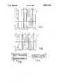
- FIG. 1is a diagrammatic cross-section of a first embodiment of a display device according to the invention
- FIG. 2is a diagrammatic cross-section of a second embodiment of a display device according to the invention.
- FIG. 3is a diagrammatic cross-section of an interference filter for use in such display devices.
- FIG. 4is a diagrammatic cross-section of a second interference filter for use in such display devices.
- FIG. 1shows diagrammatically a liquid crystal display device having a liquid crystal 2 as an electro-optical medium present between two parallel transparent substrates 3, 4 of, for example, glass.
- Transparent strip-shaped electrodes 5, 6, of, for example tin oxide,are provided on these substrates, defining a matrix of switching elements.
- the electrodesare coated in this embodiment with a layer of orienting material 7 of, for example silicon oxide.
- the devicecomprises a pattern 8 of luminescent materials which are provided in accordance with a given arrangement and which radiate in this embodiment red, green and blue light if they are irradiated by, for example UV light 9 from a radiation source 10.
- the red, green and blue phosphor dotscoincide with the switching points defined by the electrodes 5 and 6, while the liquid crystal 2 serves as a light switch for the light generated in the phosphors.
- the devicealso comprises a polariser 11 and an analyser 12 for visible radiation, as well as a substrate 13 of a material which is transparent to UV radiation such as, for example quartz.
- an interference filter 14which substantially completely passes the UV light 9 and substantially completely reflects light generated in the phosphors is arranged between the radiation source 10 and the phosphor pattern 8. Thereby, light generated in the phosphor layer 8 which would otherwise leave the phosphor layer 8 on the side of the filter 14 is reflected by this filter 14 and thus contributes to the total light output. In this way a greater brightness (2 to 3 times) is obtained than if the interference filter 14 were not provided.
- this filtersubstantially completely reflects the light generated in the phosphor layer 8, unwanted reflections on surfaces located between the phosphor layer 8 and the radiation source 10 are avoided so that the resolution and the contrast of such a display device are considerably improved.
- liquid crystalline material 8Various types of materials may be chosen for the liquid crystalline material 8.
- the so-called twisted nematic materialsmay be used, but materials whose operation is based on birefringence may also be used such as are described, for example in EP No. 0,131,216 (270° twist) or in DE No. 34,31,871 (180° twist) or ferro-electric liquid crystals.
- the inventionmay also be used for other electro-optical display devices which are driven in the transmission mode such as, for example (dry) electroscopic displays.
- FIG. 2shows a further embodiment of a device according to the invention.
- the liquid crystal material 2functions as an UV radiation switch and the phosphor pattern 8 is present on the viewing side of the device.
- the liquid crystal material and UV wavelength usedcan be optimized in such a way that a maximum contrast is achieved.
- the liquid ROTN 3010 from Hoffmann-Larocheis chosen for the liquid crystal material and the wavelength of the exciting radiation 9 is approximately 370 nm.
- the cell structureis such that a twist of the director of approximately 270° occurs (SBE cell) between the surfaces of the two orientation layers 7.
- SBE cella twist of the director of approximately 270° occurs
- the polariser 11 and the analyser 12are not suitable for UV radiation, and the substrates 3 and 4 are transparent to UV light. If desired, an extra glass plate (transparent to UV light) may be arranged between the analyser 12 and the interference filter 14. The analyser 12 and the filter 14 may also change places.
- the structure of the interference filter 14There are various possibilities for the structure of the interference filter 14. For example, use can be made of a so-called "all-dielectric" multilayer filter comprising a minimum number of 20 layers alternately having a high and a low refractive index.
- FIG. 3shows such a filter 14 comprising 30 to 40 layers 21, 22, the layers 21 consisting of a material having a low refractive index and the layers 22 consisting of a material having a high refractive index.
- magnesium fluoride (MgF 2 ) or silicon oxide (SiO 2 )may be chosen for the layers 21, either of which materials is suitable for all wavelengths of the radiation source 10.
- Materials which may be chosen for the layers 22are, for example: hafnium oxide (HfO 2 ) which is suitable for all wavelengths; zirconium oxide (ZrO 2 ), suitable for ⁇ >350 nm; or one of the materials titanium oxide (TiO 2 ), tantalum oxide (Ta 2 O 5 ) or niobium oxide (Nb 2 O 5 ), which are suitable for ⁇ >370 nm.
- hafnium oxideHfO 2
- ZrO 2zirconium oxide
- TiO 2titanium oxide
- Ta 2 O 5tantalum oxide
- Nb 2 O 5niobium oxide
- the filtermay be in the form of a "metal-dielectric" filter (see FIG. 4) of 3-5 layers, in this embodiment 5 layers, alternately having a metal layer 23 and a dielectric layer 24.
- Both filtersmay be manufactured by means of electron-beam vapour-deposition techniques, while the filter of FIG. 4 may alternatively be obtained by means of sputtering.
- the radiation source 10is a UV source which directly emits the 254 nm Hg resonance line (for example, a low pressure mercury lamp with a quartz envelope). Although at this wavelength quartz must also be chosen for the substrates 3 and 13, phosphors for the display of blue, green and red which are very efficient at this wavelength are known, such as:
- a long-wave UV sourcesuch as a high pressure mercury lamp may alternatively be chosen as a radiation source.
- a radiation sourceis chosen which emits radiation in the wavelength range of 350-380 nm, for example a high-pressure mercury lamp.
- normal glassinstead of quartz glass can be chosen for the embodiment of FIG. 1, and ZnS:Ag (blue phosphor), (Zn,Cd)S:Cu,Al (green phosphor) and Y 2 O 2 S:Eu (red phosphor) are suitable as phosphors.
- the phosphor layer and the interference filter in this embodimentmay be entirely provided on the outside (viewing side). To prevent parallax, the UV light 9 must then be substantially parallel.
- electro-optical elementvarious types of LCD, such as TN-LCD, SBE, HBE, FELCD, electroscopic displays, etc.).
- a pattern-shaped second interference filter registering with the phosphor dotsmay be arranged on the other side (viewing side) of the phosphor layer, which filter only passes light at a small spatial angle and in which extra brightness is obtained at a small angle because the reflection greatly increases for light rays extending at an angle of more than 20° to 35° to the normal on the filter.
- Such brightness-enhancing interference filtershave been described for monochrome display devices in commonly assigned co-pending application Ser. No. 134,433, filed simultaneously herewith.
- Such a filteroffers an additional advantage in that the previously mentioned spatial broadening is compensated, which may be useful in data display devices (data graphic displays).
Landscapes
- Physics & Mathematics (AREA)
- Nonlinear Science (AREA)
- Mathematical Physics (AREA)
- Chemical & Material Sciences (AREA)
- Crystallography & Structural Chemistry (AREA)
- General Physics & Mathematics (AREA)
- Optics & Photonics (AREA)
- Engineering & Computer Science (AREA)
- Multimedia (AREA)
- Signal Processing (AREA)
- Liquid Crystal (AREA)
- Devices For Indicating Variable Information By Combining Individual Elements (AREA)
- Control Of El Displays (AREA)
- Control Of Indicators Other Than Cathode Ray Tubes (AREA)
- Control Of Gas Discharge Display Tubes (AREA)
- Optical Filters (AREA)
- Vehicle Body Suspensions (AREA)
- Diaphragms For Electromechanical Transducers (AREA)
- Measuring Pulse, Heart Rate, Blood Pressure Or Blood Flow (AREA)
- Illuminated Signs And Luminous Advertising (AREA)
Abstract
Description
Co-pending application Ser. No. 134,433, filed simultaneously with and assigned to the same assignee as this application, relates to a projection device having an electro-optic monochrome display device including a luminescent layer and interference filters.
The invention relates to a display device comprising an electro-optical medium between two parallel transparent substrates having drive means to influence the transmission state of the electro-optical medium, one of the substrates having a pattern of at least two luminescent materials, said display device comprising a radiation source suitable for emitting sufficiently short-wave radiation to excite the luminescent materials.
The said display devices are used, for example in colour television or in colour monitors for the purpose of data display in computer systems, and in, for example display devices in dashboards etc.
A display device of the type mentioned in the opening paragraph is described in British Patent Specification No. 2,154,355. In the device shown in this specification a liquid crystal display device consisting of a liquid crystalline material between two glass plates is driven in the transmission mode. The device is exposed with UV radiation on one side, while the glass plate on the side of the UV source is coated with a pattern of phosphors. The areas associated with this pattern can be separately switched by means of switching electrodes.
The ultraviolet radiation emitted by the UV source produces conversion in the luminescent layers into a colour in the visible part of the spectrum (for example, into the primary colours red, green and blue) so that visible light passes to the other side of the device in dependence on the state of the electro-optical medium to form a (colour) picture.
However, in this conversion a large part of the quantity of light generated in the phosphors is lost. In fact, the conversion is effected within a very thin layer (approximately 2 to 3 microns) on the side of the incident ultraviolet radiation. Since the generated visible light is emitted in all directions and is also dispersed by the phosphors, a large part thereof (approximately 60 to 70%) leaves the phosphor layer on the side of the UV source. This leads of course to a lower brightness, but moreover a part of the light generated in the phosphors may be dispersed back via reflection from various surfaces (for example a glass-air surface when the luminescent material between the UV source and the electro-optical medium is provided on a glass substrate), and then at an unacceptably large spatial angle or in undesired areas. All this leads to a loss of resolution and a decresed contrast.
It is an object of the invention to provide a display device in which the said drawbacks are at least substantially obviated. It is based on the recognition that notably the said loss of light due to emission and dispersion in the direction of the radiation source can be substantially prevented.
To this end a color display device according to the invention is characterized in that an interference filter is arranged between the radiation source and the luminescent materials, which filter substantially completely passes the short-wave radiation and substantially completely reflects radiation generated in the luminescent materials.
By using such an interference filter the radiation required for excitation, for example a characteristic wavelength of 254 nm (Hg resonance line) or a wavelength range of 360-380 nm is passed either for all angles of incidence or for a selected angle range. Furthermore the presence of the filter causes light which is generated in the phosphor layer and is emitted in the direction of the radiation source to be substantially completely reflected by the filter for all angles of incidence. A light output gain which may be a factor of 2 to 3 is then obtained with respect to a device without an interference filter.
An additional advantage is that there are substantially no reflections against surfaces located closer to the radiation source because substantially all radiation in the direction of the source is reflected by the interference filter. Consequently, resolution and contrast are improved considerably.
It is true that due to the reflections on the intereference filter and in the phosphor layer a small spatial broadening of a picture element (approximately 10-20 μm) occurs, but it is small with respect to the dimensions which are conventional for picture elements. In addition a possible spatial separation between picture elements, which may be experienced as being troublesome, is partly suppressed in this way.
A first embodiment of a display device according to the invention is characterized in that the interference filter and the luminescent materials are arranged between the radiation source and the electro-optical medium, while the electro-optical medium comprises a light switch for the radiation generated in the luminescent materials.
The phosphors preferably emit visible light, for example the three primary colours red, green and blue, while the electro-optical medium will generally be a liquid crystalline medium, although electroscopic displays may be used alternatively.
A second embodiment is characterized in that the interference filter is arranged between the electro-optical medium and the luminescent materials on the side of the electro-optical medium remote from the radiation source, while the electro-optical medium comprises a switch for the radiation exciting the luminescent materials.
There are also various possibilities for the nature of the interference filter used. For example, a so-called all-dielectric multi-layer filter comprising at least 20 but preferably 30 to 40 layers alternately having a high and a low refractive index may be chosen. An advantage thereof is that no absorption occurs in the filter, provided that the materials chosen are transparent both to the exciting and the generated radiation. The selected number of layers (at least 20) also ensures a very broad reflection band for the entire visible spectrum. On the other hand an advantageous choice is a metal-dielectric filter comprising only 3 to 5 layers of alternately a metal layer and a layer of dielectric material.
Various choices are also possible for the phosphors. When using a radiation source based on the 254 nm Hg resonance line the following combination is very satisfactory:
BaMg2 Al16 O27 :Eu as a blue phosphor (maximum emission at 450 nm);
CeMgAl11 O19 :Tb as a green phosphor (maximum emission at 545 nm);
Y2 O3 :Eu as a red phosphor (maximum emission at 612 nm).
The associated emission wavelengths are satisfactorily suitable for the maximum sensitivity of each of the three colour receptors of the eye; this renders an eminent colour rendition possible. When using a radiation source mainly with long-wave UV radiation (for example a high-pressure mercury lamp), for example ZnS:Ag (blue), (Zn,Cd)S:Cu,Al (green) and Y2 O2 S:Eu (red) are very suitable.
The invention will now be described in greater detail and by way of example with reference to the accompanying drawings in which
FIG. 1 is a diagrammatic cross-section of a first embodiment of a display device according to the invention,
FIG. 2 is a diagrammatic cross-section of a second embodiment of a display device according to the invention,
FIG. 3 is a diagrammatic cross-section of an interference filter for use in such display devices, and
FIG. 4 is a diagrammatic cross-section of a second interference filter for use in such display devices.
FIG. 1 shows diagrammatically a liquid crystal display device having aliquid crystal 2 as an electro-optical medium present between two paralleltransparent substrates shaped electrodes orienting material 7 of, for example silicon oxide.
Furthermore the device comprises apattern 8 of luminescent materials which are provided in accordance with a given arrangement and which radiate in this embodiment red, green and blue light if they are irradiated by, forexample UV light 9 from aradiation source 10. The red, green and blue phosphor dots coincide with the switching points defined by theelectrodes liquid crystal 2 serves as a light switch for the light generated in the phosphors. The device also comprises apolariser 11 and ananalyser 12 for visible radiation, as well as asubstrate 13 of a material which is transparent to UV radiation such as, for example quartz.
According to the invention aninterference filter 14 which substantially completely passes theUV light 9 and substantially completely reflects light generated in the phosphors is arranged between theradiation source 10 and thephosphor pattern 8. Thereby, light generated in thephosphor layer 8 which would otherwise leave thephosphor layer 8 on the side of thefilter 14 is reflected by thisfilter 14 and thus contributes to the total light output. In this way a greater brightness (2 to 3 times) is obtained than if theinterference filter 14 were not provided.
Since this filter substantially completely reflects the light generated in thephosphor layer 8, unwanted reflections on surfaces located between thephosphor layer 8 and theradiation source 10 are avoided so that the resolution and the contrast of such a display device are considerably improved.
It is true that due to reflections of the red, green and blue radiation from the interference filter 14 a spatial broadening of an excited point of the matrix occurs in thephosphor layer 8, but this is usually negligible (10 to 20 μm). In addition this spatial broadening may sometimes have a positive effect because spatially fully separated colour regions are perceived by the eye as substantially tangent (or even overlapping each other to a slight extent), which most observers experience as a pleasant phenomenon.
Various types of materials may be chosen for the liquidcrystalline material 8. For example, the so-called twisted nematic materials may be used, but materials whose operation is based on birefringence may also be used such as are described, for example in EP No. 0,131,216 (270° twist) or in DE No. 34,31,871 (180° twist) or ferro-electric liquid crystals.
On the other hand the invention may also be used for other electro-optical display devices which are driven in the transmission mode such as, for example (dry) electroscopic displays.
FIG. 2 shows a further embodiment of a device according to the invention. Theliquid crystal material 2 functions as an UV radiation switch and thephosphor pattern 8 is present on the viewing side of the device. The liquid crystal material and UV wavelength used can be optimized in such a way that a maximum contrast is achieved. In the relevant embodiment the liquid ROTN 3010 from Hoffmann-Laroche is chosen for the liquid crystal material and the wavelength of theexciting radiation 9 is approximately 370 nm. The cell structure is such that a twist of the director of approximately 270° occurs (SBE cell) between the surfaces of the two orientation layers 7. The remaining reference numerals of FIG. 2 denote the same components as those in FIG. 1. It is to be noted that thepolariser 11 and theanalyser 12 are not suitable for UV radiation, and thesubstrates analyser 12 and theinterference filter 14. Theanalyser 12 and thefilter 14 may also change places.
There are various possibilities for the structure of theinterference filter 14. For example, use can be made of a so-called "all-dielectric" multilayer filter comprising a minimum number of 20 layers alternately having a high and a low refractive index. FIG. 3 shows such afilter 14 comprising 30 to 40layers 21, 22, thelayers 21 consisting of a material having a low refractive index and the layers 22 consisting of a material having a high refractive index. For example, magnesium fluoride (MgF2) or silicon oxide (SiO2) may be chosen for thelayers 21, either of which materials is suitable for all wavelengths of theradiation source 10. Materials which may be chosen for the layers 22 are, for example: hafnium oxide (HfO2) which is suitable for all wavelengths; zirconium oxide (ZrO2), suitable for λ>350 nm; or one of the materials titanium oxide (TiO2), tantalum oxide (Ta2 O5) or niobium oxide (Nb2 O5), which are suitable for λ>370 nm.
Alternatively, the filter may be in the form of a "metal-dielectric" filter (see FIG. 4) of 3-5 layers, in thisembodiment 5 layers, alternately having ametal layer 23 and adielectric layer 24.
Both filters may be manufactured by means of electron-beam vapour-deposition techniques, while the filter of FIG. 4 may alternatively be obtained by means of sputtering.
In the embodiment of FIG. 1, theradiation source 10 is a UV source which directly emits the 254 nm Hg resonance line (for example, a low pressure mercury lamp with a quartz envelope). Although at this wavelength quartz must also be chosen for thesubstrates
BaMg2 Al16 O27 :Eu as a blue phosphor, λmax =450 nm;
CeMgAl11 O19 :Tb as a green phosphor, λmax =545 nm;
Y2 O3 :Eu as a red phosphor, λmax =612 nm.
In this embodiment a long-wave UV source such as a high pressure mercury lamp may alternatively be chosen as a radiation source.
For the embodiment of FIG. 2, a radiation source is chosen which emits radiation in the wavelength range of 350-380 nm, for example a high-pressure mercury lamp. In this case normal glass instead of quartz glass can be chosen for the embodiment of FIG. 1, and ZnS:Ag (blue phosphor), (Zn,Cd)S:Cu,Al (green phosphor) and Y2 O2 S:Eu (red phosphor) are suitable as phosphors.
The phosphor layer and the interference filter in this embodiment may be entirely provided on the outside (viewing side). To prevent parallax, theUV light 9 must then be substantially parallel.
As already stated, a wide choice is also possible with respect to the electro-optical element (various types of LCD, such as TN-LCD, SBE, HBE, FELCD, electroscopic displays, etc.).
Finally a pattern-shaped second interference filter registering with the phosphor dots may be arranged on the other side (viewing side) of the phosphor layer, which filter only passes light at a small spatial angle and in which extra brightness is obtained at a small angle because the reflection greatly increases for light rays extending at an angle of more than 20° to 35° to the normal on the filter. Such brightness-enhancing interference filters have been described for monochrome display devices in commonly assigned co-pending application Ser. No. 134,433, filed simultaneously herewith.
Such a filter offers an additional advantage in that the previously mentioned spatial broadening is compensated, which may be useful in data display devices (data graphic displays).
The invention is of course not limited to the embodiments referred to. Several variations within the scope of the invention are possible and will become apparent to those skilled in the art.
Claims (10)
1. A color display device comprising: an electro-optical medium; two parallel transparent substrates flanking the medium and having drive means to influence the transmission state of the medium; a pattern of at least two luminescent materials on one of the substrates; and a radiation source suitable for emitting sufficiently short-wave radiation to excite the luminescent materials,
characterized in that an interference filter is arranged between the radiation source and the luminescent materials, which filter is substantially coplanar and coextensive with the radiation source and the luminescent materials, and substantially completely passes the short-wave radiation and substantially completely reflects radiation generated in the luminescent materials.
2. A display device as claimed in claim 1, characterized in that the interference filter and the luminescent materials are arranged between the radiation source and the electro-optical medium, and the electro-optical medium comprises a light switch for the radiation generated in the luminescent materials.
3. A display device as claimed in claim 1, characterized in that the interference filter is arranged between the electro-optical medium and the luminescent materials on the side of the electro-optical medium remote from the radiation source, and the electro-optical medium comprises a switch for the radiation exciting the luminescent materials.
4. A display device as claimed in claim 1, characterized in that the electro-optical medium comprises a liquid crystalline material.
5. A display device as claimed in claim 1, characterized in that the interference filter is a dielectric filter comprising at least 20 layers alternately having a high and a low refractive index, said layers substantially completely passing the exciting radiation and substantially completely reflecting the radiation generated in the luminescent materials.
6. A display device as claimed in claim 5, characterized in that the layers having a high refractive index comprise one or more of the materials hafnium oxide (HfO2), zirconium oxide (ZrO2), titanium oxide (TiO2), tantalum oxide (TaO5) or niobium oxide (Nb2 O5), and the layers having a low refractive index comprise one or more of the materials magnesium fluoride (MgF2) or silicon oxide (SiO2).
7. A display device as claimed in claim 1, characterized in that the interference filter comprises 3-5 layers of alternately a metal layer and a layer of dielectric material.
8. A display device as claimed in claim 1, characterized in that the radiation source emits radiation at a central wavelength of 254 nm and in that one or more of the following materials are chosen for the luminescent material:
BaMg2 Al16 O27 :Eu as a blue phosphor;
CeMgAl11 O19 :Tb as a green phosphor;
Y2 O3 :Eu as a red phosphor.
9. A display device as claimed in claim 1, characterized in that the radiation source emits radiation at a wavelength in the range of 360-380 nm.
10. A display device as claimed in claim 1, characterized in that a pattern-shaped second interference filter is arranged on the other side of the pattern of luminescent material, whereby the reflection greatly increases for light rays which extend at an angle of more than 20° to 35° to the normal on the filter.
Applications Claiming Priority (2)
| Application Number | Priority Date | Filing Date | Title |
|---|---|---|---|
| NL8603298 | 1986-12-24 | ||
| NL8603298 | 1986-12-24 |
Publications (1)
| Publication Number | Publication Date |
|---|---|
| US4822144Atrue US4822144A (en) | 1989-04-18 |
Family
ID=19849059
Family Applications (1)
| Application Number | Title | Priority Date | Filing Date |
|---|---|---|---|
| US07/134,432Expired - Fee RelatedUS4822144A (en) | 1986-12-24 | 1987-12-17 | Electro-optic color display including luminescent layer and interference filter |
Country Status (8)
| Country | Link |
|---|---|
| US (1) | US4822144A (en) |
| EP (1) | EP0272760B1 (en) |
| JP (1) | JPH0769541B2 (en) |
| KR (1) | KR880008672A (en) |
| CN (1) | CN1014360B (en) |
| AT (1) | ATE86765T1 (en) |
| AU (1) | AU8293187A (en) |
| DE (1) | DE3784660T2 (en) |
Cited By (70)
| Publication number | Priority date | Publication date | Assignee | Title |
|---|---|---|---|---|
| US4950058A (en)* | 1988-01-11 | 1990-08-21 | Commissariat A L'energie Atomique | Active matrix color display screen without crossing of address line conductors and command column conductors |
| US4965562A (en)* | 1987-05-13 | 1990-10-23 | U.S. Philips Corporation | Electroscopic display device |
| US5121233A (en)* | 1990-04-18 | 1992-06-09 | Harris Corporation | Multi-color display |
| US5146355A (en)* | 1986-10-23 | 1992-09-08 | Litton Systems Canada Limited | Transflective mode liquid crystal display with phosphor illumination |
| WO1993004393A1 (en)* | 1991-08-19 | 1993-03-04 | Smiths Industries, Inc. | Improved lighting technique for color displays |
| US5298351A (en)* | 1990-06-25 | 1994-03-29 | International Business Machines Corporation | Ablation mask and use thereof |
| US5504597A (en)* | 1992-06-17 | 1996-04-02 | Xerox Corporation | Full color display with gradient index lens array disposed between phosphor emitters and liquid crystal display |
| US5569977A (en)* | 1994-03-08 | 1996-10-29 | Philips Electronics North America Corporation | Cathode ray tube with UV-reflective filter and UV-excitable phosphor |
| US5666174A (en)* | 1995-08-11 | 1997-09-09 | Cupolo, Iii; Anthony M. | Emissive liquid crystal display with liquid crystal between radiation source and phosphor layer |
| US5734454A (en)* | 1993-12-08 | 1998-03-31 | Matsushita Electric Industrial Co., Ltd. | Liquid crystal panel with reducing means, manufacturing method therefor and projection display apparatus using the same |
| US5734457A (en)* | 1995-05-25 | 1998-03-31 | Sharp Kabushiki Kaisha | Color display device having absorptive and reflective color filters |
| US5813752A (en)* | 1997-05-27 | 1998-09-29 | Philips Electronics North America Corporation | UV/blue LED-phosphor device with short wave pass, long wave pass band pass and peroit filters |
| US5813753A (en)* | 1997-05-27 | 1998-09-29 | Philips Electronics North America Corporation | UV/blue led-phosphor device with efficient conversion of UV/blues light to visible light |
| WO1999009452A1 (en)* | 1997-08-15 | 1999-02-25 | The Secretary Of State For Defence | Display with a dielectric stack filter |
| WO1999061897A1 (en)* | 1998-05-26 | 1999-12-02 | California Institute Of Technology | Efficient color display using non-absorbing color filters |
| US6097456A (en)* | 1998-08-12 | 2000-08-01 | California Institute Of Technology | Efficient color display using low-absorption in-pixel color filters |
| US6124912A (en)* | 1997-06-09 | 2000-09-26 | National Semiconductor Corporation | Reflectance enhancing thin film stack in which pairs of dielectric layers are on a reflector and liquid crystal is on the dielectric layers |
| WO2000057239A1 (en)* | 1999-03-23 | 2000-09-28 | Koninklijke Philips Electronics N.V. | Display device and method of manufacturing such a display device |
| US6147723A (en)* | 1992-12-22 | 2000-11-14 | Canon Kabushiki Kaisha | Display device with multilayer film between LCD and backlight |
| US6155699A (en)* | 1999-03-15 | 2000-12-05 | Agilent Technologies, Inc. | Efficient phosphor-conversion led structure |
| US6191834B1 (en)* | 1996-01-11 | 2001-02-20 | Screen Technology Limited | Liquid crystal cell |
| US6284306B1 (en) | 1992-12-21 | 2001-09-04 | U.S. Philips Corporation | Method of manufacturing a filtering layer of silicon dioxide on a display screen |
| US20010055208A1 (en)* | 2000-06-15 | 2001-12-27 | Koichi Kimura | Optical element, optical light source unit and optical display device equipped with the optical light source unit |
| WO2002005021A1 (en)* | 2000-07-12 | 2002-01-17 | Nec Corporation | Liquid crystal display |
| US6373188B1 (en)* | 1998-12-22 | 2002-04-16 | Honeywell International Inc. | Efficient solid-state light emitting device with excited phosphors for producing a visible light output |
| US6384886B2 (en) | 1998-06-12 | 2002-05-07 | Semiconductor Energy Laboratory Co., Ltd. | Electrooptical display device using an active matrix display in which a light reflection film having a flat surface over the pixel electrode and the textured body, and the pixel electrode having a flat surface |
| US6386720B1 (en) | 1995-08-01 | 2002-05-14 | Canon Kabushiki Kaisha | Light source device and optical apparatus |
| US6426787B1 (en)* | 1998-06-16 | 2002-07-30 | Semiconductor Energy Laboratory Co., Ltd. | Electronic device and method of manufacturing the same having dielectric multi-layers on the pixel electrode |
| EP1116988A3 (en)* | 2000-01-14 | 2003-06-04 | Philips Intellectual Property & Standards GmbH | Liquid crystal display with fluorescent front panel |
| US20030141800A1 (en)* | 1999-02-24 | 2003-07-31 | Koninklijke Philips Electronics N.V. | Display device comprising a light guide |
| US20030166943A1 (en)* | 2001-12-13 | 2003-09-04 | Merck Patent Gesellschaft Mit Beschrankter Haftung | Oxadiazole derivative and its use as charge transport and light emitting material |
| US6646702B1 (en)* | 1999-03-31 | 2003-11-11 | Kyocera Corporation | Liquid crystal display device having a semi-transmissive dielectric film |
| US6654079B2 (en) | 2000-01-14 | 2003-11-25 | Koninklijke Philips Electronics N.V. | Liquid crystal color display screen comprising a phosphor layer |
| US6683659B2 (en) | 2000-09-14 | 2004-01-27 | Koninklijke Philips Electronics N.V. | Liquid crystal display screen with backlighting |
| US6717348B2 (en) | 1999-12-09 | 2004-04-06 | Fuji Photo Film Co., Ltd. | Display apparatus |
| US20040212291A1 (en)* | 2000-03-14 | 2004-10-28 | Keuper Matthijs Hendrik | Light-emitting diode, lighting device and method of manufacturing same |
| US6891583B1 (en)* | 1997-07-03 | 2005-05-10 | Eidgenössische Technische Hochschule Zurich | Photoluminescent display devices having a photoluminescent layer with a high degree of polarization in its absorption, and methods for making the same |
| US20050174512A1 (en)* | 2003-08-04 | 2005-08-11 | Soo-Guy Roh | Liquid crystal display assembly |
| US20050185267A1 (en)* | 2004-02-23 | 2005-08-25 | Optical Coating Laboratory, Inc., A Jds Uniphase Company | Metal-dielectric coating for image sensor lids |
| US20050237448A1 (en)* | 2004-04-23 | 2005-10-27 | Innolux Display Corp. | Color filter and method for manufacturing the same |
| US20060002141A1 (en)* | 2004-06-30 | 2006-01-05 | Ouderkirk Andrew J | Phosphor based illumination system having a short pass reflector and method of making same |
| US20060001037A1 (en)* | 2004-06-30 | 2006-01-05 | Schardt Craig R | Phosphor based illumination system having a plurality of light guides and a display using same |
| US20060002101A1 (en)* | 2004-06-30 | 2006-01-05 | Wheatley John A | Phosphor based illumination system having a long pass reflector and method of making same |
| US20060002108A1 (en)* | 2004-06-30 | 2006-01-05 | Ouderkirk Andrew J | Phosphor based illumination system having a short pass reflector and method of making same |
| US20060002678A1 (en)* | 2004-06-30 | 2006-01-05 | Weber Michael F | Phosphor based illumination system having a long pass reflector and method of making same |
| US20060002131A1 (en)* | 2004-06-30 | 2006-01-05 | Schultz John C | Phosphor based illumination system having a plurality of light guides and a display using same |
| US20060238671A1 (en)* | 2005-04-20 | 2006-10-26 | Samsung Electronics Co., Ltd. | Photo-luminescence liquid crystal display |
| US7129763B1 (en)* | 2004-11-08 | 2006-10-31 | Western Digital Technologies, Inc. | Adjusting power consumption of digital circuitry by generating frequency error representing error in propagation delay |
| US20060256253A1 (en)* | 2005-05-10 | 2006-11-16 | Dae-Jin Park | Liquid crystal display |
| US20060274226A1 (en)* | 2005-06-02 | 2006-12-07 | Samsung Electronics Co., Ltd. | Photo-luminescent liquid crystal display |
| US20070007881A1 (en)* | 2005-04-29 | 2007-01-11 | Kim Byung-Ki | Photo-luminescent liquid crystal display |
| US7205805B1 (en) | 2004-11-02 | 2007-04-17 | Western Digital Technologies, Inc. | Adjusting power consumption of digital circuitry relative to critical path circuit having the largest propagation delay error |
| US20070097478A1 (en)* | 2005-10-31 | 2007-05-03 | Hewlett-Packard Development Company, L.C. | Charge responsive optical material |
| US20070097291A1 (en)* | 2005-10-31 | 2007-05-03 | Hewlett-Packard Development Company, Lp | Polymer dispersed liquid crystal |
| US7235792B2 (en) | 2004-05-19 | 2007-06-26 | Carl Scott Elofson | Color-tuned volumetric light using high quantum yield nanocrystals |
| US20070285945A1 (en)* | 2006-06-13 | 2007-12-13 | Lg.Philips Lcd Co., Ltd. | Backlight unit and liquid crystal display device using the same |
| US7330019B1 (en) | 2006-10-31 | 2008-02-12 | Western Digital Technologies, Inc. | Adjusting on-time for a discontinuous switching voltage regulator |
| US20080083930A1 (en)* | 2006-01-25 | 2008-04-10 | Edmond John A | Transparent Ohmic Contacts on Light Emitting Diodes with Growth Substrates |
| US7486060B1 (en) | 2006-03-30 | 2009-02-03 | Western Digital Technologies, Inc. | Switching voltage regulator comprising a cycle comparator for dynamic voltage scaling |
| US20090147497A1 (en)* | 2007-12-07 | 2009-06-11 | Sony Corporation | Illumination apparatus, color conversion device, and display apparatus |
| US7551383B1 (en) | 2006-06-28 | 2009-06-23 | Western Digital Technologies, Inc. | Adjusting voltage delivered to disk drive circuitry based on a selected zone |
| US20090231515A1 (en)* | 2008-03-11 | 2009-09-17 | Microsoft Corporation | Photoluminescent backlighting of light valve |
| US7612859B2 (en) | 2005-10-31 | 2009-11-03 | Hewlett-Packard Development Company, L.P. | Ultra-violet radiation absorbing grid |
| US20090322728A1 (en)* | 2008-06-27 | 2009-12-31 | Samsung Electronics Co., Ltd. | LDC panel driver with self masking function using power on reset signal and driving method thereof |
| US7733189B1 (en) | 2007-09-14 | 2010-06-08 | Western Digital Technologies, Inc. | Oscillator comprising foldover detection |
| USRE41685E1 (en)* | 1999-12-28 | 2010-09-14 | Honeywell International, Inc. | Light source with non-white and phosphor-based white LED devices, and LCD assembly |
| US20110205214A1 (en)* | 2008-09-04 | 2011-08-25 | Yukio Kizaki | Display device and method of driving the same |
| US8085020B1 (en) | 2008-06-13 | 2011-12-27 | Western Digital Technologies, Inc. | Switching voltage regulator employing dynamic voltage scaling with hysteretic comparator |
| US8937404B1 (en) | 2010-08-23 | 2015-01-20 | Western Digital Technologies, Inc. | Data storage device comprising dual mode independent/parallel voltage regulators |
| US10126587B2 (en) | 2015-09-18 | 2018-11-13 | Samsung Electronics Co., Ltd. | Display device |
Families Citing this family (22)
| Publication number | Priority date | Publication date | Assignee | Title |
|---|---|---|---|---|
| US4949005A (en)* | 1988-11-14 | 1990-08-14 | General Electric Company | Tantala-silica interference filters and lamps using same |
| JPH03233501A (en)* | 1990-02-09 | 1991-10-17 | Copal Co Ltd | Optical multilayered film filter element and production thereof |
| GB9300361D0 (en)* | 1993-01-09 | 1993-03-03 | Smiths Industries Plc | Displays |
| KR100315106B1 (en)* | 1994-07-26 | 2002-02-19 | 김순택 | Display element |
| DE10012326A1 (en)* | 2000-03-14 | 2001-09-20 | Philips Corp Intellectual Pty | Liquid crystal color screen has a light source, a polarizer, a liquid crystal cell, a front plate, and a photoluminescent layer containing a dichroic absorbing dye and an isotropic emitting dye |
| US6506480B2 (en)* | 2001-02-16 | 2003-01-14 | 3M Innovative Properties Company | Color shifting film with a plurality of fluorescent colorants |
| DE10132699A1 (en)* | 2001-07-05 | 2003-01-16 | Philips Corp Intellectual Pty | Organic electroluminescent display device with optical filter |
| US8252040B2 (en) | 2001-07-20 | 2012-08-28 | Microvention, Inc. | Aneurysm treatment device and method of use |
| JP2006501617A (en)* | 2002-10-01 | 2006-01-12 | コーニンクレッカ フィリップス エレクトロニクス エヌ ヴィ | Electroluminescent display with improved light external coupling |
| AU2003278009A1 (en)* | 2002-10-18 | 2004-05-04 | Ifire Technology Inc. | Color electroluminescent displays |
| US7430355B2 (en) | 2003-12-08 | 2008-09-30 | University Of Cincinnati | Light emissive signage devices based on lightwave coupling |
| US7262758B2 (en)* | 2004-06-09 | 2007-08-28 | Eastman Kodak Company | Display device using vertical cavity laser arrays |
| FR2882423B1 (en)* | 2005-02-22 | 2007-03-30 | Saint Gobain | LUMINOUS STRUCTURE PLANE OR SIGNIFICANTLY PLANE |
| JP2007052197A (en)* | 2005-08-17 | 2007-03-01 | Sony Corp | Flat light source device and color liquid crystal display device assembly |
| WO2009003049A2 (en) | 2007-06-25 | 2008-12-31 | Micro Vention, Inc. | Self-expanding prosthesis |
| RU2512091C2 (en) | 2008-12-02 | 2014-04-10 | Конинклейке Филипс Электроникс Н.В. | Light-emitting diode unit |
| US9711688B2 (en) | 2008-12-02 | 2017-07-18 | Koninklijke Philips N.V. | Controlling LED emission pattern using optically active materials |
| JP2010225373A (en)* | 2009-03-23 | 2010-10-07 | Sony Corp | Color conversion sheet, illumination device, and display device |
| CN102804040A (en)* | 2009-06-12 | 2012-11-28 | 夏普株式会社 | Display panel and display device |
| US8809811B2 (en)* | 2012-09-13 | 2014-08-19 | Prysm, Inc. | Reduction of intensity ringing in fluorescent displays |
| KR101859637B1 (en)* | 2013-08-23 | 2018-05-18 | 삼성전자주식회사 | Back light unit and liquid crystal display apparatus having the same |
| US10309615B2 (en) | 2015-02-09 | 2019-06-04 | Sun Chemical Corporation | Light emissive display based on lightwave coupling in combination with visible light illuminated content |
Citations (4)
| Publication number | Priority date | Publication date | Assignee | Title |
|---|---|---|---|---|
| DE2619368A1 (en)* | 1976-04-30 | 1977-11-17 | Siemens Ag | Alphanumeric liq. crystal display - includes fluorescent plate having light apertures each with dielectric reflector |
| US4634926A (en)* | 1984-07-20 | 1987-01-06 | U.S. Philips Corporation | Display tube provided with an interference filter |
| US4678285A (en)* | 1984-01-13 | 1987-07-07 | Ricoh Company, Ltd. | Liquid crystal color display device |
| US4772885A (en)* | 1984-11-22 | 1988-09-20 | Ricoh Company, Ltd. | Liquid crystal color display device |
Family Cites Families (2)
| Publication number | Priority date | Publication date | Assignee | Title |
|---|---|---|---|---|
| DE2835347A1 (en)* | 1978-08-11 | 1980-02-28 | Fraunhofer Ges Forschung | DISPLAY DEVICE WITH AN ELECTROOPTIC LIGHT VALVE |
| US4799050A (en)* | 1986-10-23 | 1989-01-17 | Litton Systems Canada Limited | Full color liquid crystal display |
- 1987
- 1987-12-17USUS07/134,432patent/US4822144A/ennot_activeExpired - Fee Related
- 1987-12-18EPEP87202581Apatent/EP0272760B1/ennot_activeExpired - Lifetime
- 1987-12-18ATAT87202581Tpatent/ATE86765T1/ennot_activeIP Right Cessation
- 1987-12-18DEDE8787202581Tpatent/DE3784660T2/ennot_activeExpired - Fee Related
- 1987-12-21CNCN87105954Apatent/CN1014360B/ennot_activeExpired
- 1987-12-22AUAU82931/87Apatent/AU8293187A/ennot_activeAbandoned
- 1987-12-24KRKR870014901Apatent/KR880008672A/ennot_activeWithdrawn
- 1987-12-24JPJP32816887Apatent/JPH0769541B2/ennot_activeExpired - Lifetime
Patent Citations (4)
| Publication number | Priority date | Publication date | Assignee | Title |
|---|---|---|---|---|
| DE2619368A1 (en)* | 1976-04-30 | 1977-11-17 | Siemens Ag | Alphanumeric liq. crystal display - includes fluorescent plate having light apertures each with dielectric reflector |
| US4678285A (en)* | 1984-01-13 | 1987-07-07 | Ricoh Company, Ltd. | Liquid crystal color display device |
| US4634926A (en)* | 1984-07-20 | 1987-01-06 | U.S. Philips Corporation | Display tube provided with an interference filter |
| US4772885A (en)* | 1984-11-22 | 1988-09-20 | Ricoh Company, Ltd. | Liquid crystal color display device |
Non-Patent Citations (2)
| Title |
|---|
| Spiller, Eberhard, "High Quality Fabry-Perot Mirrors for the Ultraviolet," Optik, vol. 39, (No. 2), Dec. 1973, pp. 118-125. |
| Spiller, Eberhard, High Quality Fabry Perot Mirrors for the Ultraviolet, Optik, vol. 39, (No. 2), Dec. 1973, pp. 118 125.* |
Cited By (115)
| Publication number | Priority date | Publication date | Assignee | Title |
|---|---|---|---|---|
| US5146355A (en)* | 1986-10-23 | 1992-09-08 | Litton Systems Canada Limited | Transflective mode liquid crystal display with phosphor illumination |
| US4965562A (en)* | 1987-05-13 | 1990-10-23 | U.S. Philips Corporation | Electroscopic display device |
| US4950058A (en)* | 1988-01-11 | 1990-08-21 | Commissariat A L'energie Atomique | Active matrix color display screen without crossing of address line conductors and command column conductors |
| US5121233A (en)* | 1990-04-18 | 1992-06-09 | Harris Corporation | Multi-color display |
| US5298351A (en)* | 1990-06-25 | 1994-03-29 | International Business Machines Corporation | Ablation mask and use thereof |
| WO1993004393A1 (en)* | 1991-08-19 | 1993-03-04 | Smiths Industries, Inc. | Improved lighting technique for color displays |
| US5504597A (en)* | 1992-06-17 | 1996-04-02 | Xerox Corporation | Full color display with gradient index lens array disposed between phosphor emitters and liquid crystal display |
| US6284306B1 (en) | 1992-12-21 | 2001-09-04 | U.S. Philips Corporation | Method of manufacturing a filtering layer of silicon dioxide on a display screen |
| US6147723A (en)* | 1992-12-22 | 2000-11-14 | Canon Kabushiki Kaisha | Display device with multilayer film between LCD and backlight |
| US5734454A (en)* | 1993-12-08 | 1998-03-31 | Matsushita Electric Industrial Co., Ltd. | Liquid crystal panel with reducing means, manufacturing method therefor and projection display apparatus using the same |
| US6333770B1 (en) | 1993-12-08 | 2001-12-25 | Matsushita Electric Industrial Co., Ltd. | Liquid crystal panel with reducing means, manufacturing method therefore and projection display apparatus using the same |
| US5963283A (en)* | 1993-12-08 | 1999-10-05 | Matsushita Electric Industrial Co., Ltd | Liquid crystal panel with reducing means, manufacturing method therefor and projection display apparatus using the same |
| US5569977A (en)* | 1994-03-08 | 1996-10-29 | Philips Electronics North America Corporation | Cathode ray tube with UV-reflective filter and UV-excitable phosphor |
| US5734457A (en)* | 1995-05-25 | 1998-03-31 | Sharp Kabushiki Kaisha | Color display device having absorptive and reflective color filters |
| US6386720B1 (en) | 1995-08-01 | 2002-05-14 | Canon Kabushiki Kaisha | Light source device and optical apparatus |
| US5666174A (en)* | 1995-08-11 | 1997-09-09 | Cupolo, Iii; Anthony M. | Emissive liquid crystal display with liquid crystal between radiation source and phosphor layer |
| US6191834B1 (en)* | 1996-01-11 | 2001-02-20 | Screen Technology Limited | Liquid crystal cell |
| WO1998054930A3 (en)* | 1997-05-27 | 1999-04-08 | Koninkl Philips Electronics Nv | Uv/blue led-phosphor device with enhanced light output |
| US5813752A (en)* | 1997-05-27 | 1998-09-29 | Philips Electronics North America Corporation | UV/blue LED-phosphor device with short wave pass, long wave pass band pass and peroit filters |
| US5813753A (en)* | 1997-05-27 | 1998-09-29 | Philips Electronics North America Corporation | UV/blue led-phosphor device with efficient conversion of UV/blues light to visible light |
| US6124912A (en)* | 1997-06-09 | 2000-09-26 | National Semiconductor Corporation | Reflectance enhancing thin film stack in which pairs of dielectric layers are on a reflector and liquid crystal is on the dielectric layers |
| US6891583B1 (en)* | 1997-07-03 | 2005-05-10 | Eidgenössische Technische Hochschule Zurich | Photoluminescent display devices having a photoluminescent layer with a high degree of polarization in its absorption, and methods for making the same |
| WO1999009452A1 (en)* | 1997-08-15 | 1999-02-25 | The Secretary Of State For Defence | Display with a dielectric stack filter |
| WO1999061897A1 (en)* | 1998-05-26 | 1999-12-02 | California Institute Of Technology | Efficient color display using non-absorbing color filters |
| US6819378B2 (en) | 1998-06-12 | 2004-11-16 | Semiconductor Energy Laboratory Co., Ltd. | Electrooptical display device having textured body on flat surface of pixel electrode |
| US6384886B2 (en) | 1998-06-12 | 2002-05-07 | Semiconductor Energy Laboratory Co., Ltd. | Electrooptical display device using an active matrix display in which a light reflection film having a flat surface over the pixel electrode and the textured body, and the pixel electrode having a flat surface |
| US6426787B1 (en)* | 1998-06-16 | 2002-07-30 | Semiconductor Energy Laboratory Co., Ltd. | Electronic device and method of manufacturing the same having dielectric multi-layers on the pixel electrode |
| US20040174490A1 (en)* | 1998-06-16 | 2004-09-09 | Semiconductor Energy Laboratory Co., Ltd. | Electronic device and method of manufacturing the same |
| US6707521B2 (en)* | 1998-06-16 | 2004-03-16 | Semiconductor Energy Laboratory Co., Ltd. | Electronic device and method of manufacturing the same |
| US7362398B2 (en)* | 1998-06-16 | 2008-04-22 | Semiconductor Energy Laboratory Co., Ltd. | Camera and personal computer having a reflection type liquid crystal device with particular dielectric multi-layer film and interlayer insulating films |
| US6097456A (en)* | 1998-08-12 | 2000-08-01 | California Institute Of Technology | Efficient color display using low-absorption in-pixel color filters |
| US6373188B1 (en)* | 1998-12-22 | 2002-04-16 | Honeywell International Inc. | Efficient solid-state light emitting device with excited phosphors for producing a visible light output |
| US20030141800A1 (en)* | 1999-02-24 | 2003-07-31 | Koninklijke Philips Electronics N.V. | Display device comprising a light guide |
| US6908217B2 (en)* | 1999-02-24 | 2005-06-21 | Koninklijke Philips Electronics N.V. | Display device comprising a light guide |
| US6155699A (en)* | 1999-03-15 | 2000-12-05 | Agilent Technologies, Inc. | Efficient phosphor-conversion led structure |
| US6320633B1 (en) | 1999-03-23 | 2001-11-20 | U.S. Philips Corporation | Display device and method of manufacturing such a display device |
| WO2000057239A1 (en)* | 1999-03-23 | 2000-09-28 | Koninklijke Philips Electronics N.V. | Display device and method of manufacturing such a display device |
| US6646702B1 (en)* | 1999-03-31 | 2003-11-11 | Kyocera Corporation | Liquid crystal display device having a semi-transmissive dielectric film |
| US6717348B2 (en) | 1999-12-09 | 2004-04-06 | Fuji Photo Film Co., Ltd. | Display apparatus |
| USRE41685E1 (en)* | 1999-12-28 | 2010-09-14 | Honeywell International, Inc. | Light source with non-white and phosphor-based white LED devices, and LCD assembly |
| EP1116988A3 (en)* | 2000-01-14 | 2003-06-04 | Philips Intellectual Property & Standards GmbH | Liquid crystal display with fluorescent front panel |
| US6654079B2 (en) | 2000-01-14 | 2003-11-25 | Koninklijke Philips Electronics N.V. | Liquid crystal color display screen comprising a phosphor layer |
| US20040212291A1 (en)* | 2000-03-14 | 2004-10-28 | Keuper Matthijs Hendrik | Light-emitting diode, lighting device and method of manufacturing same |
| US7535168B2 (en)* | 2000-03-14 | 2009-05-19 | Philips Lumiled Lighting, U.S. Llc | Light-emitting diode, lighting device and method of manufacturing same |
| US6798469B2 (en)* | 2000-06-15 | 2004-09-28 | Fuji Photo Film Co., Ltd. | Optical element, optical light source unit and optical display device equipped with the optical light source unit |
| US20010055208A1 (en)* | 2000-06-15 | 2001-12-27 | Koichi Kimura | Optical element, optical light source unit and optical display device equipped with the optical light source unit |
| WO2002005021A1 (en)* | 2000-07-12 | 2002-01-17 | Nec Corporation | Liquid crystal display |
| US6683659B2 (en) | 2000-09-14 | 2004-01-27 | Koninklijke Philips Electronics N.V. | Liquid crystal display screen with backlighting |
| US6863841B2 (en) | 2001-12-13 | 2005-03-08 | Merck Patent Gmbh | Oxadiazole derivative and its use as charge transport and light emitting material |
| US20030166943A1 (en)* | 2001-12-13 | 2003-09-04 | Merck Patent Gesellschaft Mit Beschrankter Haftung | Oxadiazole derivative and its use as charge transport and light emitting material |
| US20050174512A1 (en)* | 2003-08-04 | 2005-08-11 | Soo-Guy Roh | Liquid crystal display assembly |
| US7349044B2 (en)* | 2003-08-04 | 2008-03-25 | Samsung Electronics Co., Ltd. | Liquid crystal display assembly having the interference filter disposed corresponding exclusively to the green region |
| US20050185267A1 (en)* | 2004-02-23 | 2005-08-25 | Optical Coating Laboratory, Inc., A Jds Uniphase Company | Metal-dielectric coating for image sensor lids |
| US7133197B2 (en) | 2004-02-23 | 2006-11-07 | Jds Uniphase Corporation | Metal-dielectric coating for image sensor lids |
| US20050237448A1 (en)* | 2004-04-23 | 2005-10-27 | Innolux Display Corp. | Color filter and method for manufacturing the same |
| US7235792B2 (en) | 2004-05-19 | 2007-06-26 | Carl Scott Elofson | Color-tuned volumetric light using high quantum yield nanocrystals |
| WO2006007302A1 (en)* | 2004-06-30 | 2006-01-19 | 3M Innovative Properties Company | Phosphor based illumination system having a plurality of light guides and a display using same |
| US7357555B2 (en) | 2004-06-30 | 2008-04-15 | 3M Innovative Properties Company | Phosphor based illumination system having an interference reflector and a display |
| US20060002141A1 (en)* | 2004-06-30 | 2006-01-05 | Ouderkirk Andrew J | Phosphor based illumination system having a short pass reflector and method of making same |
| US20060001037A1 (en)* | 2004-06-30 | 2006-01-05 | Schardt Craig R | Phosphor based illumination system having a plurality of light guides and a display using same |
| US20060002131A1 (en)* | 2004-06-30 | 2006-01-05 | Schultz John C | Phosphor based illumination system having a plurality of light guides and a display using same |
| US7497608B2 (en) | 2004-06-30 | 2009-03-03 | 3M Innovative Properties Company | Phosphor based illumination system having a long pass reflector and method of making same |
| US7407313B2 (en) | 2004-06-30 | 2008-08-05 | 3M Innovative Properties Company | Phosphor based illumination system having a plurality of light guides and a display using same |
| US7377679B2 (en) | 2004-06-30 | 2008-05-27 | 3M Innovative Properties Company | Phosphor based illumination system having a plurality of light guides and a display using same |
| US7182498B2 (en) | 2004-06-30 | 2007-02-27 | 3M Innovative Properties Company | Phosphor based illumination system having a plurality of light guides and an interference reflector |
| US7204631B2 (en) | 2004-06-30 | 2007-04-17 | 3M Innovative Properties Company | Phosphor based illumination system having a plurality of light guides and an interference reflector |
| US20060002101A1 (en)* | 2004-06-30 | 2006-01-05 | Wheatley John A | Phosphor based illumination system having a long pass reflector and method of making same |
| US7204630B2 (en) | 2004-06-30 | 2007-04-17 | 3M Innovative Properties Company | Phosphor based illumination system having a plurality of light guides and an interference reflector |
| WO2006007283A1 (en)* | 2004-06-30 | 2006-01-19 | 3M Innovative Properties Company | Phosphor based illumination system having a long pass reflector and method of making same |
| US7357554B2 (en) | 2004-06-30 | 2008-04-15 | 3M Innovative Properties Company | Phosphor based illumination system having a light guide, an interference reflector and a display |
| US7213958B2 (en) | 2004-06-30 | 2007-05-08 | 3M Innovative Properties Company | Phosphor based illumination system having light guide and an interference reflector |
| US20070127262A1 (en)* | 2004-06-30 | 2007-06-07 | 3M Innovative Properties Company | Phosphor based illumination system having a plurality of light guides and a display using same |
| US20060002678A1 (en)* | 2004-06-30 | 2006-01-05 | Weber Michael F | Phosphor based illumination system having a long pass reflector and method of making same |
| US20070147076A1 (en)* | 2004-06-30 | 2007-06-28 | 3M Innovative Properties Company | Phosphor based illumination system having a long pass reflector and method of making same |
| US7255469B2 (en) | 2004-06-30 | 2007-08-14 | 3M Innovative Properties Company | Phosphor based illumination system having a light guide and an interference reflector |
| US20070189035A1 (en)* | 2004-06-30 | 2007-08-16 | 3M Innovative Properties Company | Phosphor based illumination system having a short pass reflector and method of making same |
| US20070195549A1 (en)* | 2004-06-30 | 2007-08-23 | 3M Innovative Properties Company | Phosphor Based Illumination System Having a Plurality of Light Guides and a Display Using Same |
| US20070274098A1 (en)* | 2004-06-30 | 2007-11-29 | 3M Innovative Properties Company | Phosphor based illumination system having a long pass reflector and method of making same |
| US20070285943A1 (en)* | 2004-06-30 | 2007-12-13 | 3M Innovative Properties Company | Phosphor based illumination system having an interference reflector and a display |
| US7350953B2 (en) | 2004-06-30 | 2008-04-01 | 3M Innovative Properties Company | Phosphor based illumination system having a short pass reflector and method of making same |
| US20060002108A1 (en)* | 2004-06-30 | 2006-01-05 | Ouderkirk Andrew J | Phosphor based illumination system having a short pass reflector and method of making same |
| US7205805B1 (en) | 2004-11-02 | 2007-04-17 | Western Digital Technologies, Inc. | Adjusting power consumption of digital circuitry relative to critical path circuit having the largest propagation delay error |
| US7129763B1 (en)* | 2004-11-08 | 2006-10-31 | Western Digital Technologies, Inc. | Adjusting power consumption of digital circuitry by generating frequency error representing error in propagation delay |
| US20060238671A1 (en)* | 2005-04-20 | 2006-10-26 | Samsung Electronics Co., Ltd. | Photo-luminescence liquid crystal display |
| US7649594B2 (en)* | 2005-04-29 | 2010-01-19 | Samsung Electronics Co., Ltd. | Photo-luminescent liquid crystal display |
| US20070007881A1 (en)* | 2005-04-29 | 2007-01-11 | Kim Byung-Ki | Photo-luminescent liquid crystal display |
| US20060256253A1 (en)* | 2005-05-10 | 2006-11-16 | Dae-Jin Park | Liquid crystal display |
| US20060274226A1 (en)* | 2005-06-02 | 2006-12-07 | Samsung Electronics Co., Ltd. | Photo-luminescent liquid crystal display |
| US7746423B2 (en) | 2005-06-02 | 2010-06-29 | Samsung Electronics Co., Ltd. | Photo-luminescent liquid crystal display including a blue dichroic mirror layer |
| US20070097478A1 (en)* | 2005-10-31 | 2007-05-03 | Hewlett-Packard Development Company, L.C. | Charge responsive optical material |
| US7876400B2 (en) | 2005-10-31 | 2011-01-25 | Hewlett-Packard Development Company, L.P. | Optical modulation system |
| US7612859B2 (en) | 2005-10-31 | 2009-11-03 | Hewlett-Packard Development Company, L.P. | Ultra-violet radiation absorbing grid |
| US20070097291A1 (en)* | 2005-10-31 | 2007-05-03 | Hewlett-Packard Development Company, Lp | Polymer dispersed liquid crystal |
| US20080083930A1 (en)* | 2006-01-25 | 2008-04-10 | Edmond John A | Transparent Ohmic Contacts on Light Emitting Diodes with Growth Substrates |
| US8101961B2 (en)* | 2006-01-25 | 2012-01-24 | Cree, Inc. | Transparent ohmic contacts on light emitting diodes with growth substrates |
| US7486060B1 (en) | 2006-03-30 | 2009-02-03 | Western Digital Technologies, Inc. | Switching voltage regulator comprising a cycle comparator for dynamic voltage scaling |
| US8912778B1 (en) | 2006-03-30 | 2014-12-16 | Western Digital Technologies, Inc. | Switching voltage regulator employing current pre-adjust based on power mode |
| US7520653B2 (en)* | 2006-06-13 | 2009-04-21 | Lg Display Co., Ltd. | Backlight unit and liquid crystal display device using the same |
| US20070285945A1 (en)* | 2006-06-13 | 2007-12-13 | Lg.Philips Lcd Co., Ltd. | Backlight unit and liquid crystal display device using the same |
| US7551383B1 (en) | 2006-06-28 | 2009-06-23 | Western Digital Technologies, Inc. | Adjusting voltage delivered to disk drive circuitry based on a selected zone |
| US7330019B1 (en) | 2006-10-31 | 2008-02-12 | Western Digital Technologies, Inc. | Adjusting on-time for a discontinuous switching voltage regulator |
| US7733189B1 (en) | 2007-09-14 | 2010-06-08 | Western Digital Technologies, Inc. | Oscillator comprising foldover detection |
| US20090147497A1 (en)* | 2007-12-07 | 2009-06-11 | Sony Corporation | Illumination apparatus, color conversion device, and display apparatus |
| EP2068193A3 (en)* | 2007-12-07 | 2009-10-07 | Sony Corporation | Illumination apparatus, color conversion device, and display apparatus |
| US8075148B2 (en) | 2007-12-07 | 2011-12-13 | Sony Corporation | Illumination apparatus, color conversion device, and display apparatus |
| US7834956B2 (en)* | 2008-03-11 | 2010-11-16 | Microsoft Corporation | Photoluminescent backlighting of and infrared transmissive visible light barrier for light valve |
| US20090231515A1 (en)* | 2008-03-11 | 2009-09-17 | Microsoft Corporation | Photoluminescent backlighting of light valve |
| US8085020B1 (en) | 2008-06-13 | 2011-12-27 | Western Digital Technologies, Inc. | Switching voltage regulator employing dynamic voltage scaling with hysteretic comparator |
| US20090322728A1 (en)* | 2008-06-27 | 2009-12-31 | Samsung Electronics Co., Ltd. | LDC panel driver with self masking function using power on reset signal and driving method thereof |
| US8319769B2 (en)* | 2008-06-27 | 2012-11-27 | Samsung Electronics Co., Ltd. | LCD panel driver with self masking function using power on reset signal and driving method thereof |
| US8810557B2 (en)* | 2008-09-04 | 2014-08-19 | Kabushiki Kaisha Toshiba | Display device and method of driving the same |
| US20110205214A1 (en)* | 2008-09-04 | 2011-08-25 | Yukio Kizaki | Display device and method of driving the same |
| US8937404B1 (en) | 2010-08-23 | 2015-01-20 | Western Digital Technologies, Inc. | Data storage device comprising dual mode independent/parallel voltage regulators |
| US10126587B2 (en) | 2015-09-18 | 2018-11-13 | Samsung Electronics Co., Ltd. | Display device |
| US10520765B2 (en) | 2015-09-18 | 2019-12-31 | Samsung Electronics Co., Ltd. | Display device |
Also Published As
| Publication number | Publication date |
|---|---|
| JPS63172120A (en) | 1988-07-15 |
| CN87105954A (en) | 1988-07-06 |
| EP0272760A1 (en) | 1988-06-29 |
| AU8293187A (en) | 1988-06-30 |
| EP0272760B1 (en) | 1993-03-10 |
| DE3784660D1 (en) | 1993-04-15 |
| KR880008672A (en) | 1988-08-31 |
| JPH0769541B2 (en) | 1995-07-31 |
| CN1014360B (en) | 1991-10-16 |
| DE3784660T2 (en) | 1993-09-09 |
| ATE86765T1 (en) | 1993-03-15 |
Similar Documents
| Publication | Publication Date | Title |
|---|---|---|
| US4822144A (en) | Electro-optic color display including luminescent layer and interference filter | |
| EP0275601B1 (en) | Projection device and associated display device | |
| US5146355A (en) | Transflective mode liquid crystal display with phosphor illumination | |
| JP4124186B2 (en) | Liquid crystal display | |
| EP0978004A1 (en) | Collimator | |
| KR100656695B1 (en) | Transmissive Reflective Liquid Crystal Display | |
| EP0569922A1 (en) | Liquid crystal panel and liquid crystal projection TV receiver set | |
| JPS6339057B2 (en) | ||
| JP2002524772A (en) | Arrangement of light emitters for liquid crystal displays | |
| JPH1090677A (en) | Reflection type display device and its color development method | |
| EP1004053A1 (en) | Display with a dielectric stack filter | |
| KR100613437B1 (en) | Reflective transmission liquid crystal display | |
| KR100237218B1 (en) | Liquid crystal display using phosphor emission | |
| KR100283568B1 (en) | Liquid crystal display | |
| KR100310697B1 (en) | Reflection color LCD | |
| JPH06138478A (en) | Two-layer liquid crystal display device and projection display device using the same | |
| KR20010096808A (en) | Transflective Liquid Crystal Display Device | |
| JPH07104280A (en) | Filter and liquid crystal display | |
| EP0894283A1 (en) | Liquid crystal display cell using phosphor emitters | |
| JPS61103186A (en) | Light source for lighting | |
| JP2000105368A (en) | Liquid crystal display | |
| JP2004233532A (en) | Liquid crystal display device | |
| KR19990024947A (en) | Reflective color liquid crystal display device | |
| JP2000111891A (en) | Liquid crystal display device |
Legal Events
| Date | Code | Title | Description |
|---|---|---|---|
| AS | Assignment | Owner name:U.S. PHILIPS CORPORATION, 100 EAST 42ND STREET, NE Free format text:ASSIGNMENT OF ASSIGNORS INTEREST.;ASSIGNOR:VRIENS, LEENDERT;REEL/FRAME:004851/0992 Effective date:19880310 Owner name:U.S. PHILIPS CORPORATION, NEW YORK Free format text:ASSIGNMENT OF ASSIGNORS INTEREST;ASSIGNOR:VRIENS, LEENDERT;REEL/FRAME:004851/0992 Effective date:19880310 | |
| FEPP | Fee payment procedure | Free format text:PAYOR NUMBER ASSIGNED (ORIGINAL EVENT CODE: ASPN); ENTITY STATUS OF PATENT OWNER: LARGE ENTITY | |
| FPAY | Fee payment | Year of fee payment:4 | |
| FPAY | Fee payment | Year of fee payment:8 | |
| REMI | Maintenance fee reminder mailed | ||
| LAPS | Lapse for failure to pay maintenance fees | ||
| FP | Lapsed due to failure to pay maintenance fee | Effective date:20010418 | |
| STCH | Information on status: patent discontinuation | Free format text:PATENT EXPIRED DUE TO NONPAYMENT OF MAINTENANCE FEES UNDER 37 CFR 1.362 |