US4822127A - Multi-channel optical transmission system - Google Patents
Multi-channel optical transmission systemDownload PDFInfo
- Publication number
- US4822127A US4822127AUS06/874,919US87491986AUS4822127AUS 4822127 AUS4822127 AUS 4822127AUS 87491986 AUS87491986 AUS 87491986AUS 4822127 AUS4822127 AUS 4822127A
- Authority
- US
- United States
- Prior art keywords
- radiation
- optical fiber
- optical fibers
- optical
- distal end
- Prior art date
- Legal status (The legal status is an assumption and is not a legal conclusion. Google has not performed a legal analysis and makes no representation as to the accuracy of the status listed.)
- Expired - Fee Related
Links
Images


Classifications
- G—PHYSICS
- G02—OPTICS
- G02B—OPTICAL ELEMENTS, SYSTEMS OR APPARATUS
- G02B6/00—Light guides; Structural details of arrangements comprising light guides and other optical elements, e.g. couplings
- G02B6/24—Coupling light guides
- G02B6/42—Coupling light guides with opto-electronic elements
- G02B6/4201—Packages, e.g. shape, construction, internal or external details
- G02B6/4204—Packages, e.g. shape, construction, internal or external details the coupling comprising intermediate optical elements, e.g. lenses, holograms
- G02B6/4215—Packages, e.g. shape, construction, internal or external details the coupling comprising intermediate optical elements, e.g. lenses, holograms the intermediate optical elements being wavelength selective optical elements, e.g. variable wavelength optical modules or wavelength lockers
- G—PHYSICS
- G01—MEASURING; TESTING
- G01D—MEASURING NOT SPECIALLY ADAPTED FOR A SPECIFIC VARIABLE; ARRANGEMENTS FOR MEASURING TWO OR MORE VARIABLES NOT COVERED IN A SINGLE OTHER SUBCLASS; TARIFF METERING APPARATUS; MEASURING OR TESTING NOT OTHERWISE PROVIDED FOR
- G01D5/00—Mechanical means for transferring the output of a sensing member; Means for converting the output of a sensing member to another variable where the form or nature of the sensing member does not constrain the means for converting; Transducers not specially adapted for a specific variable
- G01D5/26—Mechanical means for transferring the output of a sensing member; Means for converting the output of a sensing member to another variable where the form or nature of the sensing member does not constrain the means for converting; Transducers not specially adapted for a specific variable characterised by optical transfer means, i.e. using infrared, visible, or ultraviolet light
- G01D5/268—Mechanical means for transferring the output of a sensing member; Means for converting the output of a sensing member to another variable where the form or nature of the sensing member does not constrain the means for converting; Transducers not specially adapted for a specific variable characterised by optical transfer means, i.e. using infrared, visible, or ultraviolet light using optical fibres
- G—PHYSICS
- G01—MEASURING; TESTING
- G01N—INVESTIGATING OR ANALYSING MATERIALS BY DETERMINING THEIR CHEMICAL OR PHYSICAL PROPERTIES
- G01N21/00—Investigating or analysing materials by the use of optical means, i.e. using sub-millimetre waves, infrared, visible or ultraviolet light
- G01N21/62—Systems in which the material investigated is excited whereby it emits light or causes a change in wavelength of the incident light
- G01N21/63—Systems in which the material investigated is excited whereby it emits light or causes a change in wavelength of the incident light optically excited
- G01N21/64—Fluorescence; Phosphorescence
- G01N21/6428—Measuring fluorescence of fluorescent products of reactions or of fluorochrome labelled reactive substances, e.g. measuring quenching effects, using measuring "optrodes"
- G—PHYSICS
- G02—OPTICS
- G02B—OPTICAL ELEMENTS, SYSTEMS OR APPARATUS
- G02B6/00—Light guides; Structural details of arrangements comprising light guides and other optical elements, e.g. couplings
- G02B6/24—Coupling light guides
- G02B6/26—Optical coupling means
- G02B6/28—Optical coupling means having data bus means, i.e. plural waveguides interconnected and providing an inherently bidirectional system by mixing and splitting signals
- G02B6/2804—Optical coupling means having data bus means, i.e. plural waveguides interconnected and providing an inherently bidirectional system by mixing and splitting signals forming multipart couplers without wavelength selective elements, e.g. "T" couplers, star couplers
- G—PHYSICS
- G02—OPTICS
- G02B—OPTICAL ELEMENTS, SYSTEMS OR APPARATUS
- G02B6/00—Light guides; Structural details of arrangements comprising light guides and other optical elements, e.g. couplings
- G02B6/24—Coupling light guides
- G02B6/42—Coupling light guides with opto-electronic elements
- G02B6/4201—Packages, e.g. shape, construction, internal or external details
- G02B6/4204—Packages, e.g. shape, construction, internal or external details the coupling comprising intermediate optical elements, e.g. lenses, holograms
- G—PHYSICS
- G01—MEASURING; TESTING
- G01N—INVESTIGATING OR ANALYSING MATERIALS BY DETERMINING THEIR CHEMICAL OR PHYSICAL PROPERTIES
- G01N21/00—Investigating or analysing materials by the use of optical means, i.e. using sub-millimetre waves, infrared, visible or ultraviolet light
- G01N21/62—Systems in which the material investigated is excited whereby it emits light or causes a change in wavelength of the incident light
- G01N21/63—Systems in which the material investigated is excited whereby it emits light or causes a change in wavelength of the incident light optically excited
- G01N21/64—Fluorescence; Phosphorescence
- G01N21/6428—Measuring fluorescence of fluorescent products of reactions or of fluorochrome labelled reactive substances, e.g. measuring quenching effects, using measuring "optrodes"
- G01N2021/6434—Optrodes
- G—PHYSICS
- G01—MEASURING; TESTING
- G01N—INVESTIGATING OR ANALYSING MATERIALS BY DETERMINING THEIR CHEMICAL OR PHYSICAL PROPERTIES
- G01N21/00—Investigating or analysing materials by the use of optical means, i.e. using sub-millimetre waves, infrared, visible or ultraviolet light
- G01N21/62—Systems in which the material investigated is excited whereby it emits light or causes a change in wavelength of the incident light
- G01N21/63—Systems in which the material investigated is excited whereby it emits light or causes a change in wavelength of the incident light optically excited
- G01N21/64—Fluorescence; Phosphorescence
- G01N21/645—Specially adapted constructive features of fluorimeters
- G01N2021/6484—Optical fibres
- G—PHYSICS
- G01—MEASURING; TESTING
- G01N—INVESTIGATING OR ANALYSING MATERIALS BY DETERMINING THEIR CHEMICAL OR PHYSICAL PROPERTIES
- G01N21/00—Investigating or analysing materials by the use of optical means, i.e. using sub-millimetre waves, infrared, visible or ultraviolet light
- G01N21/75—Systems in which material is subjected to a chemical reaction, the progress or the result of the reaction being investigated
- G01N21/77—Systems in which material is subjected to a chemical reaction, the progress or the result of the reaction being investigated by observing the effect on a chemical indicator
- G01N2021/7769—Measurement method of reaction-produced change in sensor
- G01N2021/7786—Fluorescence
- G—PHYSICS
- G02—OPTICS
- G02B—OPTICAL ELEMENTS, SYSTEMS OR APPARATUS
- G02B6/00—Light guides; Structural details of arrangements comprising light guides and other optical elements, e.g. couplings
- G02B6/24—Coupling light guides
- G02B6/26—Optical coupling means
- G02B6/28—Optical coupling means having data bus means, i.e. plural waveguides interconnected and providing an inherently bidirectional system by mixing and splitting signals
- G02B6/293—Optical coupling means having data bus means, i.e. plural waveguides interconnected and providing an inherently bidirectional system by mixing and splitting signals with wavelength selective means
- G02B6/29304—Optical coupling means having data bus means, i.e. plural waveguides interconnected and providing an inherently bidirectional system by mixing and splitting signals with wavelength selective means operating by diffraction, e.g. grating
- G02B6/29305—Optical coupling means having data bus means, i.e. plural waveguides interconnected and providing an inherently bidirectional system by mixing and splitting signals with wavelength selective means operating by diffraction, e.g. grating as bulk element, i.e. free space arrangement external to a light guide
- G02B6/29308—Diffractive element having focusing properties, e.g. curved gratings
- G—PHYSICS
- G02—OPTICS
- G02B—OPTICAL ELEMENTS, SYSTEMS OR APPARATUS
- G02B6/00—Light guides; Structural details of arrangements comprising light guides and other optical elements, e.g. couplings
- G02B6/24—Coupling light guides
- G02B6/26—Optical coupling means
- G02B6/28—Optical coupling means having data bus means, i.e. plural waveguides interconnected and providing an inherently bidirectional system by mixing and splitting signals
- G02B6/293—Optical coupling means having data bus means, i.e. plural waveguides interconnected and providing an inherently bidirectional system by mixing and splitting signals with wavelength selective means
- G02B6/29304—Optical coupling means having data bus means, i.e. plural waveguides interconnected and providing an inherently bidirectional system by mixing and splitting signals with wavelength selective means operating by diffraction, e.g. grating
- G02B6/29305—Optical coupling means having data bus means, i.e. plural waveguides interconnected and providing an inherently bidirectional system by mixing and splitting signals with wavelength selective means operating by diffraction, e.g. grating as bulk element, i.e. free space arrangement external to a light guide
- G02B6/2931—Diffractive element operating in reflection
- Y—GENERAL TAGGING OF NEW TECHNOLOGICAL DEVELOPMENTS; GENERAL TAGGING OF CROSS-SECTIONAL TECHNOLOGIES SPANNING OVER SEVERAL SECTIONS OF THE IPC; TECHNICAL SUBJECTS COVERED BY FORMER USPC CROSS-REFERENCE ART COLLECTIONS [XRACs] AND DIGESTS
- Y10—TECHNICAL SUBJECTS COVERED BY FORMER USPC
- Y10S—TECHNICAL SUBJECTS COVERED BY FORMER USPC CROSS-REFERENCE ART COLLECTIONS [XRACs] AND DIGESTS
- Y10S359/00—Optical: systems and elements
- Y10S359/90—Methods
Definitions
- This inventionrelates to a multi-channel electromagnetic radiation transmission system and particularly to a system which is adapted to be used in a plurality of modes for the selective determination of two or more substances in a medium. More particularly, the invention relates to a system involving a series of radiation-transmissible junctions of optical fibers, which system provides substantially unattenuated output radiation signals.
- the inventionis also concerned with a method for the determination of two or more parameters each of which is a function of the output radiation of a radiation sensitive component, utilizing said system.
- U.S. Pat. No. 4,003,707, Lubbers et al, and its reissue U.S. Pat. Re. No. 31,879disclose a method and an arrangement for measuring the concentration of gases and the pH value of a sample, e.g. blood, involving the use of a fluorescent indicator at the end of a light-conducting cable which is sealingly covered by or embedded in a selectively permeable diffusion membrane.
- the radiation transmitted to and emitted from the indicatormust be passed through various filtering elements and light elements, including reflectors, beam splitters and amplifiers before any meaningful measurements can be made.
- U.S. Pat. No. 4,041,932discloses a method whereby blood constituents are monitored by measuring the concentration of gases or fluids collected in an enclosed chamber sealingly attached to a skin "window" formed by removing the stratum corneum over a small area of the patient's skin.
- the measurements in the enclosed chamberare made, inter alia, by determining the difference in intensity of light emitted from a fluorescent indicator.
- U.S. Pat. No. 4,548,907, Seitz et aldiscloses a fluorescent-based optical sensor comprising a membrane immobilized fluorophor secured to one end of a bifurcated fiber optic channel for exposure to the sample to be analyzed.
- Sensor devices using fluorescent indicatorsmay be used for in vitro or in vivo determinations of components in physiological media.
- the size of the deviceis normally of no consequence, but for in vivo use, the size of the sensor may be extremely critical and there is an increasing need in the art to miniaturize sensor devices, particularly catheter-type devices, for the in vivo determination of components in physiological media, e.g. blood.
- diminution in size of the components of such devices, particularly in the size of the sensor itselfdecreases the strength of the signal emitted by the indicator and consequently presents problems in the detection and measurement of said signal.
- These problemsare aggravated when the detector system requires a multiplicity of components, such as filters, beamsplitters and reflectors to isolate and measure the emitted energy.
- Each of the said componentsreduces the emitted signal strength resulting in a sequential loss of measurable signal. Consequently, the more components present in the system, the weaker the final signal strength.
- the emission signal from radiation-sensitive indicatorsmay be received substantially unattenuated in a suitable detector without the necessity of filters, beam splitters, reflectors or other light elements used in the prior art.
- the concept of retained signal strength embodied in the junction coupling device of the aforesaid copending applicationis further extended in a multi-channel system, capable of numerous modifications, for the determination of a plurality of parameters, while still retaining the advantage of optimal miniaturization without loss of signal strength.
- a multi-channel electromagnetic radiation transmission systemcomprising a plurality of first cladded optical fibers each having a proximal end and a distal end, said proximal end being adapted to receive radiation from a source and said distal end having an exposed tip which substantially contacts an exposed intermediate portion of a second cladded optical fiber having a proximal end and a distal end, the contact between said tip and said second optical fiber forming a radiation-transmissible junction which is encased in an opaque, radiation reflective jacket, said second cladded optical fiber being either a single fiber having a plurality of said junctions corresponding to the number of first optical fibers located sequentially along its length or one of a plurality of fibers each having at least one of said junctions, wherein the total number of said junctions corresponds to the number of first optical fibers, the proximal end of said single second optical fiber or of each of said plurality of second optical fibers being adapted to be attached to a radiation measuring, transduc
- junctions and its associated opaque, radiation reflective jacketis substantially the same as the junction and jacket claimed in copending application Ser. No. 874,927; and it is to be understood that no claim is made herein to the individual jacket and junction device per se.
- the present inventionis concerned with a system in which a plurality of said devices is included as an essential component of a combination involving other components.
- the present inventionalso provides a method for selectively determining a plurality of parameters each of which is a function of the output radiation of a radiation sensitive component, which comprises transmitting electromagnetic radiation from a source into a system comprising a plurality of first cladded optical fibers each having a proximal end and a distal end, said proximal end being adapted to receive said radiation and said distal end having an exposed tip which substantially contacts an exposed intermediate portion of a second cladded optical fiber having a proximal end and a distal end, the contact between said tip and said second optical fiber forming a radiation-transmissible junction which is encased in an opaque, radiation reflective jacket, said second cladded optical fiber being either a single fiber having a plurality of said junctions corresponding to the number of first optical fibers located sequentially along its length or one of a plurality of fibers each having at least one of said junctions, wherein the total number of said junctions corresponds to the number of first optical fibers, said source radiation entering the system through the
- the disposition of the second optical fiber with respect to each of the first optical fibers in each said radiation-transmissible junctionis such that the output radiation from the radiation sensitive component attached to the distal end of said second optical fiber passes substantially unattenuated along said second optical fiber and through said junction to said measuring, transducing, recording or retransmitting component.
- the preferred configurationis that in which the contact between said exposed tip of each said first optical fiber and said exposed intermediate portion of said second optical fiber is substantially parallel.
- the surface of the exposed tip in contact with the second optical fiberis pre-polished to flatness.
- Each junctionalso provides a splitting of the source radiation into two components.
- a first, minor, componenttravels to the proximal end of the second optical fiber and the detector and a second, major, component travels to the distal end of the second optical fiber and the radiation-sensitive component. This provides a convenient means for source radiation compensation by measuring the ratio of the first component to the output radiation or emission signal.
- the systemmay be arranged in a number of different ways and some of these arrangements will be particularly described as preferred embodiments. It is to be understood that numerous other arrangements are possible without departing from the spirit and scope of the invention, with the proviso that in every possible arrangement the signals reaching the detector must be discernable and measurable.
- each of said first optical fibersis attached to a separate source of electromagnetic radiation of a given wavelength.
- each of said first optical fibersis coupled through a said junction to a single second optical fiber, the distal end of which is attached to a single radiation sensitive indicator and the proximal end of which is attached to a detector adapted to disperse and measure the output radiation emitted by said indicator.
- proximal ends of said plurality of first optical fibersare attached to a single source of electromagnetic radiation.
- distal end of each of said plurality of first optical fibersis coupled through a said junction to each of a plurality of said second optical fibers, the distal end of each of said second optical fibers is attached to a separate radiation sensitive indicator and the proximal ends thereof are attached to a radiation dispersing and measuring device.
- Said radiation dispersing and measuring devicepreferably comprises a grating and a two dimensional array of radiation detectors. This type of device will be described in more detail hereinafter with reference to the accompanying drawings.
- optical fibers used in the system of the inventionmay be made of any suitable material which will transmit electromagnetic radiation of the desired wavelength.
- each of said first and second cladded optical fibersis made of fused silica and the cladding is made of silicone.
- Fused silicais particularly suitable for the transmission of ultraviolet radiation.
- Each of said first optical fibers and said second optical fibermay consist of a single fiber strand or a multiple fiber bundle.
- the exposed portion of said second fiberhas a length equivalent to at least one fiber diameter.
- the opaque, radiation reflective jacketwhich encases each of the radiation transmissible junctions of the system according to the invention effectively serves two functions; namely, to reflect any radiation which might otherwise escape from the junction back into the second optical fiber and to prevent any extraneous, unwanted radiation from entering the device.
- the jacketmust be not only internally reflective, but also opaque with respect to external radiation.
- said jacketcomprises an inner layer and an outer layer, said inner layer being made of a metal foil or a metalized film whose inner surface is coated with a film of reflective material and said outer layer being made of a heat-shrinkable, opaque, non-metallic material.
- a preferred metal foil for said inner layeris aluminum foil.
- a preferred reflective materialis barium sulfate.
- Said coupling gelis a standard material in the art having substantially the same refractive index as the material of the optical fibers.
- a typical exampleis a silicone gel.
- the heat-shrinkable, opaque, non-metallic material preferably used as the outer layer of the jacketmay be any material which is opaque to ambient radiation and which may be heat shrunk around the junction to form a radiation-tight seal.
- a suitable materialis an opaque plastic, such as polyvinyl chloride.
- the outer layerextends over and beyond the inner reflective layer and overlaps the cladded portion of each of the optical fibers.
- said radiation sensitive component attached to the distal end of the second optical fiberis at least one fluorescent indicator.
- the radiation sensitive componentcomprises a plurality of indicators each of which fluoresces upon excitation by the source radiation and each of which emits radiation of a different distinguishable wavelength, the intensity of each emitted signal being dependent upon the concentration of a substance under investigation.
- a preferred source of radiation to be used with the system of the inventionis a laser which produces controlled monochromatic or polychromatic radiation.
- a further preferred embodimentis a system in which each of said first optical fibers is attached to a single polychromatic source of radiation and each of said fibers is associated with an optical filter which selects the wavelength and an optical relay which selects the timing of the radiation of a desired wavelength into said fiber.
- said optical relaycomprises a component within said first optical fiber which controls the passage of excitation source radiation into said second optical fiber, which then acts as excitation radiation for an indicator species included in the radiation sensitive component attached to the distal end of said second optical fiber.
- the resulting systemalso preferably includes means for sequentially selecting one or more excitation radiation sources transmitted through said optical relays.
- the system of the inventionis particularly suitable for use in a method for selectively determining a plurality of parameters each of which is a function of the output radiation of a radiation sensitive component.
- a preferred embodiment of the methodis one in which the parameters to be determined are the concentrations of at least two substances in at least one medium and said radiation sensitive component includes at least one fluorescent indicator whose emission radiation is dependent upon the presence of said substances.
- the signal emitted from each radiation sensitive componentis dispersed and measured in a device comprising a grating and a two dimensional array of radiation detectors.
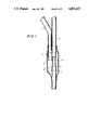
- FIG. 1is a schematic side elevation, partly in section, of a dual optical fiber device comprising a radiation transmissible junction encased in an opaque, radiation reflective jacket;
- FIG. 2is a schematic representation of one embodiment of the invention comprising three first optical fibers coupled to a single second optical fiber through three junctions located sequentially along the length of the second optical fiber;
- FIG. 3is a schematic representation of another embodiment of the invention comprising three first optical fibers coupled through junctions to three second optical fibers;
- FIG. 4is a schematic representation of a preferred radiation dispersing and measuring device comprising a grating and a two dimensional array of radiation detectors;
- FIG. 5illustrates the two dimensional array of FIG. 4.
- the devicewhich is the subject of copending application No. comprises a first cladded optical fiber 1 having an exposed tip 2.
- the fiberis made of fused silica and the cladding 3 is made of radiation-opaque silicone.
- the exposed tip of said first optical fiberis in substantially parallel contact with an exposed intermediate portion 4 of a second cladded optical fiber 5 made of the same materials as said first optical fiber.
- the contact between said tip and said second optical fiberforms a radiation-transmissible junction which is encased in an opaque, radiation reflective jacket comprising an inner layer made of aluminum foil and illustrated schematically by dashed line 6 and an outer layer 7 made of a heat-shrinkable opaque non-metallic material, for example polyvinyl chloride.
- the maximum internal diameter of the opaque heat-shrinkable tubingis about 0.01 inch (0.025 mm) when used with a standard fused silica optical silica optical fiber of about 400 ⁇ m. diameter.
- Said outer layerextends beyond the inner metal foil layer and is heat shrunk onto both the inner layer and the cladding of the optical fibers to form a radiation-tight seal around the junction.
- the aluminum foil 6is coated on its inner surface, i.e. the surface facing the junction of the optical fibers, with a film of radiation reflective material, for example barium sulfate.
- a layer of index matching optical coupling gel, for example silicone gel,is applied to said film of reflective material. This layer substantially fills the space 8 between the reflective layer and the exposed optical fibers.
- a first junction J 1 as illustrated in FIG. 1couples a first optical fiber 1 to a second optical fiber 5.
- Located sequentially along the second optical fiberare two further junctions J 2 , J 3 which, in like manner, couple the second fiber to additional first optical fibers.
- Each of said first optical fibersis adapted to receive radiation from sources S 1 , S 2 , S 3 .
- a radiation sensitive component 9Attached to the distal end of the second optical fiber is a radiation sensitive component 9.
- This componentcontains fluorescent indicators adapted to be excited by radiation of wavelengths ⁇ 1 , ⁇ 2 and ⁇ 3 from sources S 1 , S 2 and S 3 , respectively. Upon excitation, said indicators emit fluorescent radiation, the intensity of which is dependent upon the concentration of the substances under investigation.
- the emission signals from the radiation sensitive component 9travel substantially unattenuated along the second optical fiber 5 to the proximal end thereof where they are dispersed and measured by an appropriate detecting device 10 attached to said proximal end.
- the embodiment illustrated in FIG. 3comprises three first optical fibers 1 adapted to receive radiation from a single source S.
- Each of said first optical fibersis coupled through a junction J 1 , J 2 , J 3 to a separate second optical fiber 5.
- Each second optical fiberhas a radiation sensitive component 9 attached to its distal end.
- each second optical fiberis attached to a terminal of a radiation dispersing and measuring device 10 which, in this embodiment, comprises a grating and a two dimensional radiation detector.
- the signal from each second optical fiberis focussed by a concave holographic grating 11 onto a two dimensional array of radiation detectors 12.
- Said arraycomprises a series of linear sequences of radiation detectors 13; each linear sequence being adapted to receive and measure the signal from one of said second optical fibers.
- each signalprovides a visual spectrum which gives a quantitative determination of the parameter being measured.
- the system of the inventionprovides high signal resolution and accurate quantitative determination of the parameters under investigation.
Landscapes
- Physics & Mathematics (AREA)
- General Physics & Mathematics (AREA)
- Optics & Photonics (AREA)
- Health & Medical Sciences (AREA)
- Chemical & Material Sciences (AREA)
- Immunology (AREA)
- Pathology (AREA)
- Nuclear Medicine, Radiotherapy & Molecular Imaging (AREA)
- Life Sciences & Earth Sciences (AREA)
- Analytical Chemistry (AREA)
- Biochemistry (AREA)
- General Health & Medical Sciences (AREA)
- Chemical Kinetics & Catalysis (AREA)
- Optical Communication System (AREA)
- Investigating Or Analysing Materials By The Use Of Chemical Reactions (AREA)
- Measurement Of The Respiration, Hearing Ability, Form, And Blood Characteristics Of Living Organisms (AREA)
- Investigating, Analyzing Materials By Fluorescence Or Luminescence (AREA)
- Investigating Or Analysing Biological Materials (AREA)
- Light Guides In General And Applications Therefor (AREA)
- Arrangements For Transmission Of Measured Signals (AREA)
- Investigating Or Analysing Materials By Optical Means (AREA)
- Optical Couplings Of Light Guides (AREA)
- Optical Transform (AREA)
- Measurement Of Radiation (AREA)
Abstract
Description
Claims (22)
Priority Applications (12)
| Application Number | Priority Date | Filing Date | Title |
|---|---|---|---|
| US06/874,919US4822127A (en) | 1986-06-16 | 1986-06-16 | Multi-channel optical transmission system |
| ES198787305107TES2031127T3 (en) | 1986-06-16 | 1987-06-10 | MULTICHANNEL OPTICAL TRANSMISSION SYSTEM. |
| EP87305107AEP0250151B1 (en) | 1986-06-16 | 1987-06-10 | Multi-channel optical transmission system |
| AT87305107TATE75931T1 (en) | 1986-06-16 | 1987-06-10 | OPTICAL MULTICHANNEL TRANSMISSION SYSTEM. |
| DE8787305107TDE3778974D1 (en) | 1986-06-16 | 1987-06-10 | OPTICAL MULTI-CHANNEL TRANSMISSION SYSTEM. |
| CA000539585ACA1298482C (en) | 1986-06-16 | 1987-06-12 | Multi-channel optical transmission system |
| BR8702998ABR8702998A (en) | 1986-06-16 | 1987-06-12 | MULTI-CHANNEL ELECTROMAGNETIC RADIATION TRANSMISSION SYSTEM AND PROCESS TO SELECTIVELY DETERMINE A PARAMETER PLURALITY EACH OF WHICH IS A RADIATION OUTPUT FUNCTION OF A RADIATION-SENSITIVE COMPONENT |
| ZA874280AZA874280B (en) | 1986-06-16 | 1987-06-15 | Multi-channel optical transmission system |
| DK302787ADK168250B1 (en) | 1986-06-16 | 1987-06-15 | Multichannel electromagnetic radiation transmission system |
| AU74231/87AAU582693B2 (en) | 1986-06-16 | 1987-06-15 | Multi-channel Optical transmission system |
| JP62150061AJPS6311134A (en) | 1986-06-16 | 1987-06-16 | Multichannel electromagnetic radiation transmission apparatus and measurement of parameter by said apparatus |
| GR920401259TGR3004909T3 (en) | 1986-06-16 | 1992-06-11 |
Applications Claiming Priority (1)
| Application Number | Priority Date | Filing Date | Title |
|---|---|---|---|
| US06/874,919US4822127A (en) | 1986-06-16 | 1986-06-16 | Multi-channel optical transmission system |
Publications (1)
| Publication Number | Publication Date |
|---|---|
| US4822127Atrue US4822127A (en) | 1989-04-18 |
Family
ID=25364864
Family Applications (1)
| Application Number | Title | Priority Date | Filing Date |
|---|---|---|---|
| US06/874,919Expired - Fee RelatedUS4822127A (en) | 1986-06-16 | 1986-06-16 | Multi-channel optical transmission system |
Country Status (11)
| Country | Link |
|---|---|
| US (1) | US4822127A (en) |
| EP (1) | EP0250151B1 (en) |
| JP (1) | JPS6311134A (en) |
| AT (1) | ATE75931T1 (en) |
| AU (1) | AU582693B2 (en) |
| BR (1) | BR8702998A (en) |
| DE (1) | DE3778974D1 (en) |
| DK (1) | DK168250B1 (en) |
| ES (1) | ES2031127T3 (en) |
| GR (1) | GR3004909T3 (en) |
| ZA (1) | ZA874280B (en) |
Cited By (22)
| Publication number | Priority date | Publication date | Assignee | Title |
|---|---|---|---|---|
| US4992122A (en)* | 1987-10-23 | 1991-02-12 | Telephone Cables Limited | Method of coupling single-mode optical fibers to form a coupler |
| GB2258728A (en)* | 1988-12-06 | 1993-02-17 | Loughborough Consult Ltd | A fluorimeter |
| GB2228081B (en)* | 1988-12-06 | 1993-07-07 | Loughborough Consult Ltd | A fluorimeter, and a method of carrying out a fluorescent assay of a plurality of analytes |
| US5355237A (en)* | 1993-03-17 | 1994-10-11 | The United States Of America As Represented By The Administrator Of The National Aeronautics And Space Administration | Wavelength-division multiplexed optical integrated circuit with vertical diffraction grating |
| US5479548A (en)* | 1994-05-27 | 1995-12-26 | Honeywell Inc. | Fiber-optic coupler package |
| US6198557B1 (en)* | 1997-06-25 | 2001-03-06 | Deutsche Telekom Ag | Telecommunication system having frequency-dividing optical components for the parallel processing of optical pulses |
| US6266465B1 (en) | 1998-09-22 | 2001-07-24 | Baker Huges Incorporated | Angled optic fiber unions and junctions for optic fiber conduits |
| US20050129345A1 (en)* | 2002-05-28 | 2005-06-16 | Harry Schilling | Device for optical signal transmission between two units movable relative to each other |
| US7196783B2 (en) | 2002-11-15 | 2007-03-27 | Accurate Machining, Inc. | Optical fiber bundle utilizing electromagnetic radiation feedback |
| US20090018426A1 (en)* | 2007-05-10 | 2009-01-15 | Glumetrics, Inc. | Device and methods for calibrating analyte sensors |
| US20090177143A1 (en)* | 2007-11-21 | 2009-07-09 | Markle William H | Use of an equilibrium intravascular sensor to achieve tight glycemic control |
| US20090264719A1 (en)* | 2008-04-17 | 2009-10-22 | Glumetrics, Inc. | Sensor for percutaneous intravascular deployment without an indwelling cannula |
| US20100274110A1 (en)* | 2007-02-06 | 2010-10-28 | GluMetrics, Inc | Optical determination of ph and glucose |
| US20110105866A1 (en)* | 2009-11-04 | 2011-05-05 | Glumetrics, Inc. | Optical sensor configuration for ratiometric correction of blood glucose measurement |
| US20110152658A1 (en)* | 2009-12-17 | 2011-06-23 | Glumetrics, Inc. | Identification of aberrant measurements of in vivo glucose concentration using temperature |
| US8715589B2 (en) | 2009-09-30 | 2014-05-06 | Medtronic Minimed, Inc. | Sensors with thromboresistant coating |
| US8738107B2 (en) | 2007-05-10 | 2014-05-27 | Medtronic Minimed, Inc. | Equilibrium non-consuming fluorescence sensor for real time intravascular glucose measurement |
| US8838195B2 (en) | 2007-02-06 | 2014-09-16 | Medtronic Minimed, Inc. | Optical systems and methods for ratiometric measurement of blood glucose concentration |
| US9057862B2 (en) | 2010-09-21 | 2015-06-16 | Huber+Suhner Ag | Environmentally sealed cable breakout assemblies |
| CN113423340A (en)* | 2018-12-21 | 2021-09-21 | 恩吉波德全球有限公司 | Device for coupling radiation into and out of an optical fiber |
| US11224336B2 (en) | 2017-11-17 | 2022-01-18 | Canon U.S.A., Inc. | Rotational extender and/or repeater for rotating fiber based optical imaging systems, and methods and storage mediums for use therewith |
| CN115316959A (en)* | 2022-10-13 | 2022-11-11 | 浙江大学医学中心(余杭) | Three-color multi-channel optical fiber brain information recording system |
Families Citing this family (7)
| Publication number | Priority date | Publication date | Assignee | Title |
|---|---|---|---|---|
| US4927222A (en)* | 1986-06-16 | 1990-05-22 | Shiley Incorporated | Dual optical fiber device |
| JPS643805U (en)* | 1987-06-19 | 1989-01-11 | ||
| GB2242754A (en)* | 1990-03-06 | 1991-10-09 | British Telecomm | Optical fibre 1 to N splitter |
| DE4013307A1 (en)* | 1990-04-26 | 1991-10-31 | Hoechst Ag | METHOD FOR PRODUCING AN OPTICAL COUPLER FOR POLYMER LIGHTWAVE GUIDE |
| US5122441A (en)* | 1990-10-29 | 1992-06-16 | E. I. Du Pont De Nemours And Company | Method for fabricating an integral three-dimensional object from layers of a photoformable composition |
| US5176882A (en)* | 1990-12-06 | 1993-01-05 | Hewlett-Packard Company | Dual fiberoptic cell for multiple serum measurements |
| WO1992017750A1 (en)* | 1991-03-26 | 1992-10-15 | Msm Poly-Print Gmbh | Opto-electronic sensor |
Citations (15)
| Publication number | Priority date | Publication date | Assignee | Title |
|---|---|---|---|---|
| US31879A (en)* | 1861-04-02 | Machine for finishing leatheb | ||
| US4003707A (en)* | 1975-02-28 | 1977-01-18 | Max-Planck-Gesellschaft Zur Forderung Der Wissenschaften E.V. | Method and arrangement for measuring the concentration of gases |
| US4041932A (en)* | 1975-02-06 | 1977-08-16 | Fostick Moshe A | Method for monitoring blood gas tension and pH from outside the body |
| JPS5368249A (en)* | 1976-11-30 | 1978-06-17 | Hitachi Ltd | Optical wave branching method of optical fibers |
| JPS5413347A (en)* | 1977-06-30 | 1979-01-31 | Matsushita Electric Ind Co Ltd | Optical trasmission device |
| JPS54111363A (en)* | 1978-02-20 | 1979-08-31 | Matsushita Electric Ind Co Ltd | Directional photo coupler |
| US4200110A (en)* | 1977-11-28 | 1980-04-29 | United States Of America | Fiber optic pH probe |
| US4307933A (en)* | 1980-02-20 | 1981-12-29 | General Dynamics, Pomona Division | Optical fiber launch coupler |
| DE3036868A1 (en)* | 1980-09-30 | 1982-05-13 | Siemens AG, 1000 Berlin und 8000 München | Coupling, junction-forming and combining light conductor fibres - using supporting body with grooves for fixing fibres and grinding or polishing region of grooves |
| US4465335A (en)* | 1982-10-12 | 1984-08-14 | The United States Of America As Represented By The Secretary Of The Army | Concentric core optical fiber coupler |
| US4474431A (en)* | 1978-12-20 | 1984-10-02 | International Standard Electric Corporation | Optical fibre directional coupler |
| US4476870A (en)* | 1982-03-30 | 1984-10-16 | The United States Of America As Represented By The Department Of Health And Human Services | Fiber optic PO.sbsb.2 probe |
| EP0147168A2 (en)* | 1983-12-19 | 1985-07-03 | Litton Systems, Inc. | Three port coupler |
| US4548907A (en)* | 1983-09-14 | 1985-10-22 | Allied Corporation | Fluorescent fluid determination method and apparatus |
| US4649271A (en)* | 1984-01-25 | 1987-03-10 | Asea Aktiebolag | Fiber-optic acceleration sensor with photoluminescent material |
Family Cites Families (7)
| Publication number | Priority date | Publication date | Assignee | Title |
|---|---|---|---|---|
| DE2456619A1 (en)* | 1974-11-29 | 1976-08-12 | Siemens Ag | ARRANGEMENT OF BRANCHES ON MESSAGE TRANSMISSION LINES WITH OPTICAL FIBERS |
| DE2849501A1 (en)* | 1978-11-15 | 1980-05-29 | Licentia Gmbh | Optical junction coupler for data bus system - deforms initial optical fibre to transfer light energy to outer plastics sheath |
| US4706677A (en)* | 1985-09-23 | 1987-11-17 | Spectramed, Inc. | Multiple sensor bundle |
| AU6204186A (en)* | 1985-10-25 | 1987-04-30 | G. & H. Technology Inc. | Optical fibre connector |
| DD242869A1 (en)* | 1985-11-25 | 1987-02-11 | Magdeburg Medizinische Akad | OPTICAL 4-CHANNEL MULTI-MEASURING DEVICE |
| AU5538986A (en)* | 1986-04-01 | 1987-10-08 | Amalgamated Wireless (Australasia) Limited | Optical fibre |
| US4927222A (en)* | 1986-06-16 | 1990-05-22 | Shiley Incorporated | Dual optical fiber device |
- 1986
- 1986-06-16USUS06/874,919patent/US4822127A/ennot_activeExpired - Fee Related
- 1987
- 1987-06-10ATAT87305107Tpatent/ATE75931T1/ennot_activeIP Right Cessation
- 1987-06-10DEDE8787305107Tpatent/DE3778974D1/ennot_activeExpired - Fee Related
- 1987-06-10EPEP87305107Apatent/EP0250151B1/ennot_activeExpired - Lifetime
- 1987-06-10ESES198787305107Tpatent/ES2031127T3/ennot_activeExpired - Lifetime
- 1987-06-12BRBR8702998Apatent/BR8702998A/ennot_activeIP Right Cessation
- 1987-06-15AUAU74231/87Apatent/AU582693B2/ennot_activeCeased
- 1987-06-15DKDK302787Apatent/DK168250B1/ennot_activeIP Right Cessation
- 1987-06-15ZAZA874280Apatent/ZA874280B/enunknown
- 1987-06-16JPJP62150061Apatent/JPS6311134A/enactiveGranted
- 1992
- 1992-06-11GRGR920401259Tpatent/GR3004909T3/elunknown
Patent Citations (16)
| Publication number | Priority date | Publication date | Assignee | Title |
|---|---|---|---|---|
| US31879A (en)* | 1861-04-02 | Machine for finishing leatheb | ||
| US4041932A (en)* | 1975-02-06 | 1977-08-16 | Fostick Moshe A | Method for monitoring blood gas tension and pH from outside the body |
| USRE31879E (en) | 1975-02-28 | 1985-05-07 | Max-Planck-Gesellschaft Zur Forderung Der Wissenschaften E.V. | Method and arrangement for measuring the concentration of gases |
| US4003707A (en)* | 1975-02-28 | 1977-01-18 | Max-Planck-Gesellschaft Zur Forderung Der Wissenschaften E.V. | Method and arrangement for measuring the concentration of gases |
| JPS5368249A (en)* | 1976-11-30 | 1978-06-17 | Hitachi Ltd | Optical wave branching method of optical fibers |
| JPS5413347A (en)* | 1977-06-30 | 1979-01-31 | Matsushita Electric Ind Co Ltd | Optical trasmission device |
| US4200110A (en)* | 1977-11-28 | 1980-04-29 | United States Of America | Fiber optic pH probe |
| JPS54111363A (en)* | 1978-02-20 | 1979-08-31 | Matsushita Electric Ind Co Ltd | Directional photo coupler |
| US4474431A (en)* | 1978-12-20 | 1984-10-02 | International Standard Electric Corporation | Optical fibre directional coupler |
| US4307933A (en)* | 1980-02-20 | 1981-12-29 | General Dynamics, Pomona Division | Optical fiber launch coupler |
| DE3036868A1 (en)* | 1980-09-30 | 1982-05-13 | Siemens AG, 1000 Berlin und 8000 München | Coupling, junction-forming and combining light conductor fibres - using supporting body with grooves for fixing fibres and grinding or polishing region of grooves |
| US4476870A (en)* | 1982-03-30 | 1984-10-16 | The United States Of America As Represented By The Department Of Health And Human Services | Fiber optic PO.sbsb.2 probe |
| US4465335A (en)* | 1982-10-12 | 1984-08-14 | The United States Of America As Represented By The Secretary Of The Army | Concentric core optical fiber coupler |
| US4548907A (en)* | 1983-09-14 | 1985-10-22 | Allied Corporation | Fluorescent fluid determination method and apparatus |
| EP0147168A2 (en)* | 1983-12-19 | 1985-07-03 | Litton Systems, Inc. | Three port coupler |
| US4649271A (en)* | 1984-01-25 | 1987-03-10 | Asea Aktiebolag | Fiber-optic acceleration sensor with photoluminescent material |
Non-Patent Citations (2)
| Title |
|---|
| George E. Guilbault, "Practical Fluorescence" (1973)--pp. 599-600. |
| George E. Guilbault, Practical Fluorescence (1973) pp. 599 600.* |
Cited By (36)
| Publication number | Priority date | Publication date | Assignee | Title |
|---|---|---|---|---|
| US4992122A (en)* | 1987-10-23 | 1991-02-12 | Telephone Cables Limited | Method of coupling single-mode optical fibers to form a coupler |
| GB2258728A (en)* | 1988-12-06 | 1993-02-17 | Loughborough Consult Ltd | A fluorimeter |
| GB2228081B (en)* | 1988-12-06 | 1993-07-07 | Loughborough Consult Ltd | A fluorimeter, and a method of carrying out a fluorescent assay of a plurality of analytes |
| GB2258728B (en)* | 1988-12-06 | 1993-07-07 | Loughborough Consult Ltd | A fluorimeter |
| US5355237A (en)* | 1993-03-17 | 1994-10-11 | The United States Of America As Represented By The Administrator Of The National Aeronautics And Space Administration | Wavelength-division multiplexed optical integrated circuit with vertical diffraction grating |
| US5479548A (en)* | 1994-05-27 | 1995-12-26 | Honeywell Inc. | Fiber-optic coupler package |
| US6198557B1 (en)* | 1997-06-25 | 2001-03-06 | Deutsche Telekom Ag | Telecommunication system having frequency-dividing optical components for the parallel processing of optical pulses |
| US6266465B1 (en) | 1998-09-22 | 2001-07-24 | Baker Huges Incorporated | Angled optic fiber unions and junctions for optic fiber conduits |
| US20050129345A1 (en)* | 2002-05-28 | 2005-06-16 | Harry Schilling | Device for optical signal transmission between two units movable relative to each other |
| US6996300B2 (en)* | 2002-05-28 | 2006-02-07 | Schleifring Und Apparatebau Gmbh | Device for optical signal transmission between two units movable relative to each other |
| US7196783B2 (en) | 2002-11-15 | 2007-03-27 | Accurate Machining, Inc. | Optical fiber bundle utilizing electromagnetic radiation feedback |
| US9839378B2 (en) | 2007-02-06 | 2017-12-12 | Medtronic Minimed, Inc. | Optical systems and methods for ratiometric measurement of blood glucose concentration |
| US8498682B2 (en) | 2007-02-06 | 2013-07-30 | Glumetrics, Inc. | Optical determination of pH and glucose |
| US20100274110A1 (en)* | 2007-02-06 | 2010-10-28 | GluMetrics, Inc | Optical determination of ph and glucose |
| US8983565B2 (en) | 2007-02-06 | 2015-03-17 | Medtronic Minimed, Inc. | Optical determination of pH and glucose |
| US8838195B2 (en) | 2007-02-06 | 2014-09-16 | Medtronic Minimed, Inc. | Optical systems and methods for ratiometric measurement of blood glucose concentration |
| US20090018426A1 (en)* | 2007-05-10 | 2009-01-15 | Glumetrics, Inc. | Device and methods for calibrating analyte sensors |
| US8738107B2 (en) | 2007-05-10 | 2014-05-27 | Medtronic Minimed, Inc. | Equilibrium non-consuming fluorescence sensor for real time intravascular glucose measurement |
| US8979790B2 (en) | 2007-11-21 | 2015-03-17 | Medtronic Minimed, Inc. | Use of an equilibrium sensor to monitor glucose concentration |
| US8088097B2 (en) | 2007-11-21 | 2012-01-03 | Glumetrics, Inc. | Use of an equilibrium intravascular sensor to achieve tight glycemic control |
| US20090177143A1 (en)* | 2007-11-21 | 2009-07-09 | Markle William H | Use of an equilibrium intravascular sensor to achieve tight glycemic control |
| US8535262B2 (en) | 2007-11-21 | 2013-09-17 | Glumetrics, Inc. | Use of an equilibrium intravascular sensor to achieve tight glycemic control |
| US20090264719A1 (en)* | 2008-04-17 | 2009-10-22 | Glumetrics, Inc. | Sensor for percutaneous intravascular deployment without an indwelling cannula |
| US8512245B2 (en) | 2008-04-17 | 2013-08-20 | Glumetrics, Inc. | Sensor for percutaneous intravascular deployment without an indwelling cannula |
| US8715589B2 (en) | 2009-09-30 | 2014-05-06 | Medtronic Minimed, Inc. | Sensors with thromboresistant coating |
| US8700115B2 (en) | 2009-11-04 | 2014-04-15 | Glumetrics, Inc. | Optical sensor configuration for ratiometric correction of glucose measurement |
| US20110105866A1 (en)* | 2009-11-04 | 2011-05-05 | Glumetrics, Inc. | Optical sensor configuration for ratiometric correction of blood glucose measurement |
| US8467843B2 (en) | 2009-11-04 | 2013-06-18 | Glumetrics, Inc. | Optical sensor configuration for ratiometric correction of blood glucose measurement |
| US20110152658A1 (en)* | 2009-12-17 | 2011-06-23 | Glumetrics, Inc. | Identification of aberrant measurements of in vivo glucose concentration using temperature |
| US9182564B2 (en) | 2010-09-21 | 2015-11-10 | Huber + Suhner Ag | Environmentally sealed cable breakout assemblies |
| US9548601B2 (en) | 2010-09-21 | 2017-01-17 | Huber + Suhner Ag | Environmentally sealed cable breakout assemblies |
| US9057862B2 (en) | 2010-09-21 | 2015-06-16 | Huber+Suhner Ag | Environmentally sealed cable breakout assemblies |
| US11224336B2 (en) | 2017-11-17 | 2022-01-18 | Canon U.S.A., Inc. | Rotational extender and/or repeater for rotating fiber based optical imaging systems, and methods and storage mediums for use therewith |
| CN113423340A (en)* | 2018-12-21 | 2021-09-21 | 恩吉波德全球有限公司 | Device for coupling radiation into and out of an optical fiber |
| CN115316959A (en)* | 2022-10-13 | 2022-11-11 | 浙江大学医学中心(余杭) | Three-color multi-channel optical fiber brain information recording system |
| CN115316959B (en)* | 2022-10-13 | 2023-04-28 | 浙江大学医学中心(余杭) | A three-color multi-channel optical fiber brain information recording system |
Also Published As
| Publication number | Publication date |
|---|---|
| ATE75931T1 (en) | 1992-05-15 |
| JPH037370B2 (en) | 1991-02-01 |
| EP0250151A3 (en) | 1989-04-19 |
| EP0250151B1 (en) | 1992-05-13 |
| EP0250151A2 (en) | 1987-12-23 |
| DK302787A (en) | 1987-12-17 |
| DK302787D0 (en) | 1987-06-15 |
| GR3004909T3 (en) | 1993-04-28 |
| DK168250B1 (en) | 1994-02-28 |
| DE3778974D1 (en) | 1992-06-17 |
| ZA874280B (en) | 1989-01-25 |
| JPS6311134A (en) | 1988-01-18 |
| ES2031127T3 (en) | 1992-12-01 |
| BR8702998A (en) | 1988-03-08 |
| AU582693B2 (en) | 1989-04-06 |
| AU7423187A (en) | 1987-12-17 |
Similar Documents
| Publication | Publication Date | Title |
|---|---|---|
| US4822127A (en) | Multi-channel optical transmission system | |
| US4927222A (en) | Dual optical fiber device | |
| US4622974A (en) | Apparatus and method for in-vivo measurements of chemical concentrations | |
| US4833091A (en) | Sensor system | |
| US5093266A (en) | Sensor system | |
| Wolfbeis | Fibre-optic sensors in biomedical sciences | |
| US5176882A (en) | Dual fiberoptic cell for multiple serum measurements | |
| US5353792A (en) | Sensing device | |
| JP3643842B2 (en) | Glucose concentration testing device | |
| US4907857A (en) | Optical fiber distribution system for an optical fiber sensor | |
| US4344438A (en) | Optical sensor of plasma constituents | |
| US4880752A (en) | Dielectric waveguide sensors and their use in immunoassays | |
| US4735212A (en) | Multiple site fiber optic pressure transducer | |
| EP0253559A1 (en) | Sensor for measuring the concentration of a gaseous component in a fluid by absorption | |
| EP0352631A2 (en) | Optical fiber distribution system for an optical fiber sensor | |
| EP0290275B1 (en) | Examination apparatus for measuring oxygenation | |
| EP0341305A1 (en) | MODULAR CHEMICAL SENSOR MADE OF OPTICAL FIBERS. | |
| US5569911A (en) | Fiber optic system for remote fluorescent sensing using excitation and return fibers | |
| US5129022A (en) | Method and apparatus for providing reference signals from points along an optical fiber transmission path | |
| EP0305428A1 (en) | In vivo blood testing | |
| JP2002350335A (en) | Refractive index sensor, sensor system and optical fiber | |
| EP0175585B1 (en) | Dielectric waveguide sensors and their use in immunoassays | |
| US5300769A (en) | Method and system of compensating for signal artifacts in a fiber-optic sensing system | |
| CA1298482C (en) | Multi-channel optical transmission system | |
| EP0211587B1 (en) | Dielectric waveguide for use in an assay |
Legal Events
| Date | Code | Title | Description |
|---|---|---|---|
| AS | Assignment | Owner name:SHILEY INCORPORATED, 17600 GILLETTE AVENUE, IRVINE Free format text:ASSIGNMENT OF ASSIGNORS INTEREST.;ASSIGNORS:KAMIYA, TADAO;LEADER, MATTHEW J.;REEL/FRAME:004565/0228 Effective date:19860613 | |
| FEPP | Fee payment procedure | Free format text:PAYOR NUMBER ASSIGNED (ORIGINAL EVENT CODE: ASPN); ENTITY STATUS OF PATENT OWNER: LARGE ENTITY | |
| FPAY | Fee payment | Year of fee payment:4 | |
| FPAY | Fee payment | Year of fee payment:8 | |
| AS | Assignment | Owner name:BOMEDICAL SENSORS, LTD., ENGLAND Free format text:ASSIGNMENT OF ASSIGNORS INTEREST;ASSIGNOR:SHILEY, INC.;REEL/FRAME:008194/0806 Effective date:19961023 | |
| AS | Assignment | Owner name:DIAMETRICS MEDICAL LIMITED, MINNESOTA Free format text:CHANGE OF NAME;ASSIGNOR:BIOMEDICAL SENSORS LIMITED;REEL/FRAME:008579/0790 Effective date:19970407 | |
| REMI | Maintenance fee reminder mailed | ||
| LAPS | Lapse for failure to pay maintenance fees | ||
| FP | Lapsed due to failure to pay maintenance fee | Effective date:20010418 | |
| AS | Assignment | Owner name:TGC RESEARCH LIMITED, UNITED KINGDOM Free format text:ASSIGNMENT OF ASSIGNORS INTEREST;ASSIGNOR:DIAMETRICS MEDICAL LIMITED - IN LIQUIDATION;REEL/FRAME:018015/0670 Effective date:20060721 Owner name:TGC RESEARCH LIMITED, UNITED KINGDOM Free format text:ASSIGNMENT OF ASSIGNORS INTEREST;ASSIGNOR:BIOMEDICAL SENSORS LIMITED (NOW KNOWN AS DIAMETRICS MEDICAL LIMITED - IN LIQUIDATION);REEL/FRAME:018015/0694 Effective date:20060721 Owner name:TGC RESEARCH LIMITED, UNITED KINGDOM Free format text:QUITCLAIM;ASSIGNOR:DIAMETRICS MEDICAL INC.;REEL/FRAME:018015/0666 Effective date:20060724 | |
| AS | Assignment | Owner name:MEDTRONIC MINIMED, INC., CALIFORNIA Free format text:ASSIGNMENT OF ASSIGNORS INTEREST;ASSIGNOR:GLUMETRICS, INC.;REEL/FRAME:033276/0268 Effective date:20140320 | |
| STCH | Information on status: patent discontinuation | Free format text:PATENT EXPIRED DUE TO NONPAYMENT OF MAINTENANCE FEES UNDER 37 CFR 1.362 |