US4821713A - Resuscitator - Google Patents
ResuscitatorDownload PDFInfo
- Publication number
- US4821713A US4821713AUS07/080,388US8038887AUS4821713AUS 4821713 AUS4821713 AUS 4821713AUS 8038887 AUS8038887 AUS 8038887AUS 4821713 AUS4821713 AUS 4821713A
- Authority
- US
- United States
- Prior art keywords
- flow passage
- gas flow
- passage means
- gas
- wall
- Prior art date
- Legal status (The legal status is an assumption and is not a legal conclusion. Google has not performed a legal analysis and makes no representation as to the accuracy of the status listed.)
- Expired - Fee Related
Links
- 239000012528membraneSubstances0.000claimsdescription11
- 230000008878couplingEffects0.000claimsdescription5
- 238000010168coupling processMethods0.000claimsdescription5
- 238000005859coupling reactionMethods0.000claimsdescription5
- QVGXLLKOCUKJST-UHFFFAOYSA-Natomic oxygenChemical compound[O]QVGXLLKOCUKJST-UHFFFAOYSA-N0.000description14
- 229910052760oxygenInorganic materials0.000description14
- 239000001301oxygenSubstances0.000description14
- 238000010276constructionMethods0.000description4
- 210000004072lungAnatomy0.000description3
- 208000015181infectious diseaseDiseases0.000description2
- 239000003550markerSubstances0.000description2
- 208000010125myocardial infarctionDiseases0.000description2
- 230000035939shockEffects0.000description2
- 238000013022ventingMethods0.000description2
- 229920004943Delrin®Polymers0.000description1
- 208000027418Wounds and injuryDiseases0.000description1
- 230000006835compressionEffects0.000description1
- 238000007906compressionMethods0.000description1
- 230000006378damageEffects0.000description1
- 238000010348incorporationMethods0.000description1
- 208000014674injuryDiseases0.000description1
- 239000000463materialSubstances0.000description1
- 239000002991molded plasticSubstances0.000description1
- 238000000465mouldingMethods0.000description1
- 230000000149penetrating effectEffects0.000description1
- 239000004033plasticSubstances0.000description1
- 230000009467reductionEffects0.000description1
- 230000029058respiratory gaseous exchangeEffects0.000description1
- 230000004044responseEffects0.000description1
- 206010042772syncopeDiseases0.000description1
Images

Classifications
- A—HUMAN NECESSITIES
- A61—MEDICAL OR VETERINARY SCIENCE; HYGIENE
- A61M—DEVICES FOR INTRODUCING MEDIA INTO, OR ONTO, THE BODY; DEVICES FOR TRANSDUCING BODY MEDIA OR FOR TAKING MEDIA FROM THE BODY; DEVICES FOR PRODUCING OR ENDING SLEEP OR STUPOR
- A61M16/00—Devices for influencing the respiratory system of patients by gas treatment, e.g. ventilators; Tracheal tubes
- A61M16/0057—Pumps therefor
- A61M16/0078—Breathing bags
- A—HUMAN NECESSITIES
- A61—MEDICAL OR VETERINARY SCIENCE; HYGIENE
- A61M—DEVICES FOR INTRODUCING MEDIA INTO, OR ONTO, THE BODY; DEVICES FOR TRANSDUCING BODY MEDIA OR FOR TAKING MEDIA FROM THE BODY; DEVICES FOR PRODUCING OR ENDING SLEEP OR STUPOR
- A61M16/00—Devices for influencing the respiratory system of patients by gas treatment, e.g. ventilators; Tracheal tubes
- A61M16/0057—Pumps therefor
- A61M16/0084—Pumps therefor self-reinflatable by elasticity, e.g. resuscitation squeeze bags
Definitions
- This applicationis a continuation of Ser. No. 912,568, filed Sept. 29, 1986 which was a continuation-in-part of Ser. No. 882,773, filed July 7, 1986, both now abandoned.
- This inventionrelates generally to resuscitation of patients, as during heart attacks, shock, fainting, etc.; more particularly it concerns improved apparatus, characterized by high reliability, simplicity of construction, ease of use and safety against infection, and incorporation of multiple safety measures.
- the resuscitation apparatus of the inventioncomprises:
- tubing sectionsconnected or extending in series and having air inlet means connectible in air passing relation with said receptacle inlet and discharge outlet, and an air outlet connectible in air passing relation with a mask to be placed against the patient's face,
- first and second valvespositioned in at least one tubing section so that the first valve opens and passes air to said receptacle when the second valve is closed, and so that the second valve opens and passes air from the receptacle to the mask when the receptacle is squeezed and the first valve is closed,
- the air receptacletypically comprises a bellow that is substantially completely hand-collapsible, so that a minimum size receptacle may be provided.
- the tubing sectionsmay be simplified in their construction and assembly, by use of first, second and third sections, two of which are T-shaped, and each having a side opening and end openings, the side opening of the second section registered with one end opening of third section. This also simplifies valve construction incorporating flaps in that the first flap valve controls the side opening of the second opening of the first section that is in registration with the second section.
- the air bleed meansmay be positioned compactly between the air receptacle and the first flap valve.
- Another objectis the provision of air bleed means having a stopper in the form of a manually adjustable rotor having different size vent openings therein, and selectively and successively registrable with the hollow interior of the tubing section. This enables ready adjustment of the apparatus to patient's with different breathing capacities, as will be seen.
- Another objectis the provision of a re-entrant duct extending into one tubing section and defining an air discharge port that is open to communicate with the air outlet when said second flap valve is closed, the second flap valve including a flap, and the air discharge port being closed by the flap of the second flap valve when said second flap valve is open.
- a capmay be provided to control escape of air from the re-entrant air discharge duct extending into one tubing section and movable to increase or decrease the effective size of said air discharge port.
- a further objectis the provision of an air pressure response indicator means carried by said section assembly to indicate the extent of pressure build-up between the second valve and said tubing section air outlet.
- That indicator meansmay include a plunger movable to variably register with color coding, and/or other indicia, to indicate plunger position.
- an air pressure relief valvemay be provided to prevent excess pressure build-up, as will be seen.
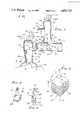
- FIG. 1is a section showing interconnected tubing sections and associated flap valves
- FIG. 2is a perspective view of a collapsible air receptacle connectible to the FIG. 1 tubing sections;
- FIG. 3is an end view on lines 3--3 of FIG. 1;
- FIG. 4is an enlarged frontal view of a valve flapper
- FIG. 5is an enlarged crosssectional view of a portion of FIG. 1;
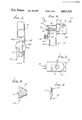
- FIG. 6is a section showing a modified tubing section
- FIG. 7is a top plan view taken on lines 7--7 of FIG. 6;
- FIG. 8is a view showing an alternative collapsible receptacle
- FIG. 9shows that receptacle in collapsed condition
- FIG. 10is fragmentary side elevation showing provision of air bleed means
- FIGS. 11a-11dare views of an air bleed rotor in different selected positions.
- FIGS. 12 and 13are fragmentary side elevations showing pressure build-up sensing structures.
- a manually collapsible air receptacle 10has an air inlet and discharge outlet 11 attached to a tubing assembly.
- the receptaclehas a bellows-like configuration to be easily hand-held, and collapsed endwise, in a direction indicated by arrow 12. Note accordion-like pleasts 10a.
- the receptaclemay have height "h”, length "l”, width "w" dimensions for convenient hand manipulation about as follows:
- the tubing assemblyincludes first, second and third tubular sections 15, 16 and 17, joined together in series, as shown.
- the assemblydefines air inlet means, as at 18, connectible in air passing relation with the receptacle inlet and outlet 11, and an air inlet and outlet 19 connectible in air passing relation with a mask 20 configured to be placed against the patient's face 21, for supplying air to the patient as via his nose 22, for resuscitation.
- tubular section 15is elbow shaped, and has tubular legs 15a and 15b; and sections 16 and 17 are alike and have tee shape. Their likeness enables reduction in molding costs, all sections consisting of molded plastic, for example.
- Section 16has tubular legs 16a and 16b, and tubular stem 16c leg 16a having telescopic interfit at 24 with leg 15b.
- Section 17has tubular legs 17a and 17b, and tubular stem 17c.
- Leg 17ahas telescopic interfit at 25 with stem 16c.
- the telescopic interfits at 24 and 26may be suitably bonded together to provide rigid connections.
- first and second flap valvesgenerally indicated at 31 and 32, and positioned in at least one tubing section, so that the first flap valve 31 opens and passes intake air to the receptacle to inflate the same when the second flap valve is closed; and so that the second flap valve 32 opens while simultaneously closing opening 71, and passes air from the receptacle (upon squeezing thereof) to the mask 20 via outlet 19, and while flap valve 31 is closed.
- the flap valvestypically include normally closed flaps 31a and 32a, the latter illustrated in closed position in FIG. 1, and flap 31a illustrated in open position in that view.
- flap 32aas having an anchor 35 penetrating and cemented to wall portion 36 of tubular section 16; a thin cantilevered flap spring arm 37, and disc 38 carried by the arm and annularly tapered at 38a to fit its annular seat 32b in wall 39, when the valve is closed.
- Valve flapper 31ais similarly configured, with parts 40, 41, 42 and 43 corresponding to parts 35, 37, 38 and 39.
- the flappermay consist of DELRIN plastic material, for example.
- Air pressure indicator meansmay be carried by the tubular section assembly, to indicate the extent of pressure build-up between valve 32 and outlet 19.
- the indicatorcomprises a movable pressure sensitive part in the form of a balloon membrane 50 exposed to the interior 51 of the elbow, and an indicator such as a slider 52 attached to the membrane.
- Increased pressure at 51expands the membrane 50 to the left in FIG. 1, pushing the slider 52 to the left.
- Indicia at 200 on slider leg 52avariably register with edge 152a of retainer 152 as the leg moves leftwardly.
- a visible indication of pressure increaseis thereby achieved, and indicia at 210 on the slider retainer 152 may indicate the degree of pressure increase, on a marker as the slider moves past the indicia 210.
- the indicatortakes the form of a plunger 56 slidable in a bore 57 formed by an insert 58 attached to the elbow.
- a safety valvemay be provided to allow escape of excess pressure so that injury to the lungs of a patient, may be prevented.
- a check valve part 60is urged by spring 61 to close outlet 62. Part 60 is pushed open by excess air pressure to allow air escape.
- a re-entrant duct 70extending into leg 15b of section 15. It defines an air discharge port 71 that is open to communicate with the air outlet 19 upon exhalation by the patient, flap valve 32 then being closed against seat 32b. Exhaled lung air then escapes via duct 70. Alternately, port 71 is closed by flap 32a when the second flap valve 32 is open, to allow air to flow from the squeezed receptacle to the mask 20. Flap 32a thus performs two functions. Note that air may flow about the re-entrant duct in each position of the flap 32a, for minimum flow restriction.
- an enlarged cap 80controls the effective size of discharge port 71, by controlling the escape of air from the re-entrant duct 70.
- the cap 80fits annularly over an annular neck 81 on the leg 16b; and the cap has an opening 82 thereon that variably registers with the duct 70 as the cap is rotated on the enlarged neck. This serves as a control for air escape upon natural exhalation by the patient, so that positive and expiratory pressure (PEEP) may be achieved if desired.
- PEEPpositive and expiratory pressure
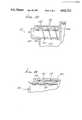
- a source of oxygen 90may be connected with the inlet 45, so that supplied O 2 enters via inlet 91 for flow to the receptacle and optional reservoir tubing 90a, and later to the patient. More particularly, a reservoir tubing 90a which has a first opened end connectable to tube section 17b and a second end (not shown) spaced from this coupling. The remote end of the oxygen reservoir is preferably an open end to allow free flow of air thereinto when necessary.
- valve 31is closed, for example when collapsible receptacle 10 is being manually compressed to ventilate the patient, the oxygen flow into inlet 45 will nevertheless continue due to the continuous flow of oxygen from the oxygen source 90.
- valve 31Because valve 31 is closed, the oxygen fed into inlet 45 will tend to flow throughout tubular section 17 and up into reservoir 90a. Then, when the collapsible reservoir 10 is released and valve 32 closed, valve 31 will again open and the oxygen which has begun to fill the oxygen reservoir 90a will be drawn down into tube section 16 and into the collapsible reservoir 10.
- an extension tube 90a to collect oxygen delivered to tubular section 17 while valve 31 is closedconstitutes an oxygen reservoir and enables collected oxygen to be fed to the collapsible reservoir when it is refilled.
- An oxygen flow rate of as little as 8 liters per minutewill supply 100% oxygen to the patient.
- FIG. 8shows an alternative conical shaped receptacle 110, for air or oxygen, for use in place of receptacle 10. Its pleats 111 allow its complete endwise collapse, manually, as shown in FIG. 9. Thus maximal air discharge is achieved; and also high compactness is achieved for storage, as in a user's pocket.
- the second tubular section 16carries air bleed means, generally indicated at 120, for controlling the amount of air passing to the mask, irrespective of the amount of manual collapse of the receptacle 10.
- the functioningis such that the user may repeatedly collapse and expand the receptacle 10 without exerting excessive air pressure on the lungs of the patient.
- the air bleed meansincludes manually adjustable air vent structure, as for example, a stopper having multiple selected positions associated with different valve openings past or through the stopper.
- FIGS. 11a-11dshow the stopper in the form of a rotor or rotatable cap 121 having an end wall 121a and a skirt 121b grippingly interfitting an annular lip 122 on the section 16. Lip 122 surrounds a smaller vent opening 123 through wall 124 of section 16.
- the end wall 121ahas different sized vent openings 125-127 therein, spaced about axis 129 of rotation, and of selectively larger size to be selectively and individually brought into registration with vent opening 123.
- Region 128 of the rotorhas no vent opening therein, and as shown in rotor position of FIG. 11a, it covers the vent 123 in wall 124. Such position would be used when maximum air flow and pressure to the patient is desired.
- minimum air flow to the patient(such as a baby) is desired, and maximum venting via 123 and 127 is effected (some air of course passing to the patient via the flap valves, as described previously).
- Vent openingsmay be covered by an elastomeric flap to function as check valves, if desired, the construction being like that of FIGS. 4 and 5.
- FIG. 12shows a plunger 130 corresponding to plunger 56 in FIG. 6, except that plunger 130 is of larger diameter, so that its end flange 130a (or other marker thereon) extends or moves closely adjacent to a transparent wall 132 of a tubular section.
- the lattercarries indicia with which the flange 130a is variably registrable as the plunger moves endwise (i.e. pressure build-up in interior 133, and the plunger moves leftwardly as resisted by light spring 134).
- Guide bore 135is provided for guiding plunger movement.
- the indicia referred tomay take the form of markings 136 on the transparent wall, as shown, so that as the plunger moves, the registration of the flange 130a with different markings is indicating changes in pressure build-up.
- Spring 134returns the plunger rightwardly as pressure drops in space 133.
- FIG. 13shows the provision of color coded indicator means 137. It is in the form of a lengthwise color coded semi-transparent sleeve 138 fitting against the bore 139 defined by wall 132. Thus, as flange 138a moves left and right, it variably registers with the different color codes on the sleeve, all of which is visible through transparent wall 132.
Landscapes
- Health & Medical Sciences (AREA)
- Pulmonology (AREA)
- Emergency Medicine (AREA)
- Engineering & Computer Science (AREA)
- Anesthesiology (AREA)
- Biomedical Technology (AREA)
- Heart & Thoracic Surgery (AREA)
- Hematology (AREA)
- Life Sciences & Earth Sciences (AREA)
- Animal Behavior & Ethology (AREA)
- General Health & Medical Sciences (AREA)
- Public Health (AREA)
- Veterinary Medicine (AREA)
- Critical Care (AREA)
- Percussion Or Vibration Massage (AREA)
Abstract
Description
This application is a continuation of Ser. No. 912,568, filed Sept. 29, 1986 which was a continuation-in-part of Ser. No. 882,773, filed July 7, 1986, both now abandoned. This invention relates generally to resuscitation of patients, as during heart attacks, shock, fainting, etc.; more particularly it concerns improved apparatus, characterized by high reliability, simplicity of construction, ease of use and safety against infection, and incorporation of multiple safety measures.
In the past, mouth-to-mouth resuscitation was believed to be necessary to provide required inhalation and exhalation of patients undergoing shock, heart attacks, etc.; however, the risk and danger of infection to the administrator of resuscitation is now recognized as serious, indeed critical, and to be avoided at all times. There is need for a simple, safe, and inexpensive resuscitation apparatus that is capable of easy manual use.
It is a major object of the invention to provide apparatus meeting the above need. Basically, the resuscitation apparatus of the invention comprises:
(a) manually collapsible air receptacle having an air inlet and discharge outlet,
(b) tubing sections connected or extending in series and having air inlet means connectible in air passing relation with said receptacle inlet and discharge outlet, and an air outlet connectible in air passing relation with a mask to be placed against the patient's face,
(c) first and second valves positioned in at least one tubing section so that the first valve opens and passes air to said receptacle when the second valve is closed, and so that the second valve opens and passes air from the receptacle to the mask when the receptacle is squeezed and the first valve is closed,
(d) and air bleed means to control the amount of air passing from the receptacle to the mask irrespective of the extent of manual collapse of the receptacle.
As will be seen, the air receptacle typically comprises a bellow that is substantially completely hand-collapsible, so that a minimum size receptacle may be provided. Also, the tubing sections may be simplified in their construction and assembly, by use of first, second and third sections, two of which are T-shaped, and each having a side opening and end openings, the side opening of the second section registered with one end opening of third section. This also simplifies valve construction incorporating flaps in that the first flap valve controls the side opening of the second opening of the first section that is in registration with the second section.
Also, the air bleed means may be positioned compactly between the air receptacle and the first flap valve.
Another object is the provision of air bleed means having a stopper in the form of a manually adjustable rotor having different size vent openings therein, and selectively and successively registrable with the hollow interior of the tubing section. This enables ready adjustment of the apparatus to patient's with different breathing capacities, as will be seen.
Another object is the provision of a re-entrant duct extending into one tubing section and defining an air discharge port that is open to communicate with the air outlet when said second flap valve is closed, the second flap valve including a flap, and the air discharge port being closed by the flap of the second flap valve when said second flap valve is open. A cap may be provided to control escape of air from the re-entrant air discharge duct extending into one tubing section and movable to increase or decrease the effective size of said air discharge port.
A further object is the provision of an air pressure response indicator means carried by said section assembly to indicate the extent of pressure build-up between the second valve and said tubing section air outlet. That indicator means may include a plunger movable to variably register with color coding, and/or other indicia, to indicate plunger position.
Finally, an air pressure relief valve may be provided to prevent excess pressure build-up, as will be seen.
These and other objects and advantages of the invention, as well as the details of an illustrative embodiment, will be more fully understood from the following specification and drawings, in which:
FIG. 1 is a section showing interconnected tubing sections and associated flap valves;
FIG. 2 is a perspective view of a collapsible air receptacle connectible to the FIG. 1 tubing sections;
FIG. 3 is an end view onlines 3--3 of FIG. 1;
FIG. 4 is an enlarged frontal view of a valve flapper;
FIG. 5 is an enlarged crosssectional view of a portion of FIG. 1;
FIG. 6 is a section showing a modified tubing section;
FIG. 7 is a top plan view taken on lines 7--7 of FIG. 6;
FIG. 8 is a view showing an alternative collapsible receptacle;
FIG. 9 shows that receptacle in collapsed condition;
FIG. 10 is fragmentary side elevation showing provision of air bleed means;
FIGS. 11a-11d are views of an air bleed rotor in different selected positions; and
FIGS. 12 and 13 are fragmentary side elevations showing pressure build-up sensing structures.
In FIGS. 1 and 2, a manuallycollapsible air receptacle 10 has an air inlet anddischarge outlet 11 attached to a tubing assembly. The receptacle has a bellows-like configuration to be easily hand-held, and collapsed endwise, in a direction indicated byarrow 12. Note accordion-like pleasts 10a. The receptacle may have height "h", length "l", width "w" dimensions for convenient hand manipulation about as follows:
h=height 4 inches
l--about 4 inches
w--about 4 inches
Almost complete collapse of the receptacle can thereby be achieved.
The tubing assembly includes first, second and thirdtubular sections outlet 11, and an air inlet andoutlet 19 connectible in air passing relation with amask 20 configured to be placed against the patient'sface 21, for supplying air to the patient as via hisnose 22, for resuscitation. As shown,tubular section 15 is elbow shaped, and hastubular legs sections Section 16 has tubular legs 16a and 16b, and tubular stem 16c leg 16a having telescopic interfit at 24 withleg 15b.Section 17 has tubular legs 17a and 17b, and tubular stem 17c. Leg 17a has telescopic interfit at 25 with stem 16c. Thus, the side opening ofsecond section 16 defined by stem 16c registers with the end opening 26 defined by leg 17a ofthird section 17. The telescopic interfits at 24 and 26 may be suitably bonded together to provide rigid connections.
Also provided are first and second flap valves generally indicated at 31 and 32, and positioned in at least one tubing section, so that thefirst flap valve 31 opens and passes intake air to the receptacle to inflate the same when the second flap valve is closed; and so that thesecond flap valve 32 opens while simultaneously closing opening 71, and passes air from the receptacle (upon squeezing thereof) to themask 20 viaoutlet 19, and whileflap valve 31 is closed. In this regard, the flap valves typically include normally closedflaps flap 31a illustrated in open position in that view. FIGS. 4 and 5show flap 32a as having ananchor 35 penetrating and cemented towall portion 36 oftubular section 16; a thin cantileveredflap spring arm 37, anddisc 38 carried by the arm and annularly tapered at 38a to fit itsannular seat 32b in wall 39, when the valve is closed. Valveflapper 31a is similarly configured, withparts parts
When thereceptacle 10 is allowed to expand (after its forcible compression) inflating air entersside inlet 45 insection 17, opensflap valve 31, and flows to the receptacle as indicated by arrow 46. At this time,flap valve 32 is closed. When the receptacle is squeezed,flap valve 31 closes, andvalve 32 opens while simultaneously closing 7, to pass air tooutlet 19 and to themask 20 to resuscitate the patient.
Air pressure indicator means may be carried by the tubular section assembly, to indicate the extent of pressure build-up betweenvalve 32 andoutlet 19. In the example shown in FIG. 1, the indicator comprises a movable pressure sensitive part in the form of aballoon membrane 50 exposed to the interior 51 of the elbow, and an indicator such as aslider 52 attached to the membrane. Increased pressure at 51 expands themembrane 50 to the left in FIG. 1, pushing theslider 52 to the left. Indicia at 200 on slider leg 52a variably register with edge 152a ofretainer 152 as the leg moves leftwardly. A visible indication of pressure increase is thereby achieved, and indicia at 210 on theslider retainer 152 may indicate the degree of pressure increase, on a marker as the slider moves past theindicia 210. In FIGS. 6 and 7, the indicator takes the form of aplunger 56 slidable in abore 57 formed by aninsert 58 attached to the elbow. The extent of plunger travel to the left, resisted by aspring 59, indicates the extent of pressure build up at 51.
A safety valve may be provided to allow escape of excess pressure so that injury to the lungs of a patient, may be prevented. As shown, acheck valve part 60 is urged by spring 61 to closeoutlet 62.Part 60 is pushed open by excess air pressure to allow air escape.
Also shown in FIG. 1 is are-entrant duct 70 extending intoleg 15b ofsection 15. It defines anair discharge port 71 that is open to communicate with theair outlet 19 upon exhalation by the patient,flap valve 32 then being closed againstseat 32b. Exhaled lung air then escapes viaduct 70. Alternately,port 71 is closed byflap 32a when thesecond flap valve 32 is open, to allow air to flow from the squeezed receptacle to themask 20.Flap 32a thus performs two functions. Note that air may flow about the re-entrant duct in each position of theflap 32a, for minimum flow restriction.
In FIGS. 6 and 7, anenlarged cap 80 controls the effective size ofdischarge port 71, by controlling the escape of air from there-entrant duct 70. To this end, thecap 80 fits annularly over anannular neck 81 on the leg 16b; and the cap has anopening 82 thereon that variably registers with theduct 70 as the cap is rotated on the enlarged neck. This serves as a control for air escape upon natural exhalation by the patient, so that positive and expiratory pressure (PEEP) may be achieved if desired.
In FIG. 1, a source ofoxygen 90 may be connected with theinlet 45, so that supplied O2 enters viainlet 91 for flow to the receptacle andoptional reservoir tubing 90a, and later to the patient. More particularly, areservoir tubing 90a which has a first opened end connectable to tube section 17b and a second end (not shown) spaced from this coupling. The remote end of the oxygen reservoir is preferably an open end to allow free flow of air thereinto when necessary. Whenvalve 31 is closed, for example whencollapsible receptacle 10 is being manually compressed to ventilate the patient, the oxygen flow intoinlet 45 will nevertheless continue due to the continuous flow of oxygen from theoxygen source 90. Becausevalve 31 is closed, the oxygen fed intoinlet 45 will tend to flow throughouttubular section 17 and up intoreservoir 90a. Then, when thecollapsible reservoir 10 is released andvalve 32 closed,valve 31 will again open and the oxygen which has begun to fill theoxygen reservoir 90a will be drawn down intotube section 16 and into thecollapsible reservoir 10. Thus, the provision of anextension tube 90a to collect oxygen delivered totubular section 17 whilevalve 31 is closed constitutes an oxygen reservoir and enables collected oxygen to be fed to the collapsible reservoir when it is refilled. An oxygen flow rate of as little as 8 liters per minute will supply 100% oxygen to the patient.
FIG. 8 shows an alternative conical shapedreceptacle 110, for air or oxygen, for use in place ofreceptacle 10. Itspleats 111 allow its complete endwise collapse, manually, as shown in FIG. 9. Thus maximal air discharge is achieved; and also high compactness is achieved for storage, as in a user's pocket.
In FIG. 10 the elements are as previously described, excepting as follows: the secondtubular section 16 carries air bleed means, generally indicated at 120, for controlling the amount of air passing to the mask, irrespective of the amount of manual collapse of thereceptacle 10. The functioning is such that the user may repeatedly collapse and expand thereceptacle 10 without exerting excessive air pressure on the lungs of the patient.
For this purpose, the air bleed means includes manually adjustable air vent structure, as for example, a stopper having multiple selected positions associated with different valve openings past or through the stopper. FIGS. 11a-11d, show the stopper in the form of a rotor orrotatable cap 121 having an end wall 121a and askirt 121b grippingly interfitting anannular lip 122 on thesection 16.Lip 122 surrounds a smaller vent opening 123 throughwall 124 ofsection 16.
The end wall 121a has different sized vent openings 125-127 therein, spaced aboutaxis 129 of rotation, and of selectively larger size to be selectively and individually brought into registration withvent opening 123.Region 128 of the rotor has no vent opening therein, and as shown in rotor position of FIG. 11a, it covers thevent 123 inwall 124. Such position would be used when maximum air flow and pressure to the patient is desired. In the rotor position of FIG. 11b, minimum air flow to the patient (such as a baby) is desired, and maximum venting via 123 and 127 is effected (some air of course passing to the patient via the flap valves, as described previously). In FIGS. 11c and 11d, intermediate positions of the rotor, lesser by-pass venting occurs, as for children, smaller adults, etc. Vent openings may be covered by an elastomeric flap to function as check valves, if desired, the construction being like that of FIGS. 4 and 5.
FIG. 12 shows aplunger 130 corresponding to plunger 56 in FIG. 6, except thatplunger 130 is of larger diameter, so that itsend flange 130a (or other marker thereon) extends or moves closely adjacent to atransparent wall 132 of a tubular section. The latter carries indicia with which theflange 130a is variably registrable as the plunger moves endwise (i.e. pressure build-up ininterior 133, and the plunger moves leftwardly as resisted by light spring 134). Guide bore 135 is provided for guiding plunger movement.
The indicia referred to may take the form ofmarkings 136 on the transparent wall, as shown, so that as the plunger moves, the registration of theflange 130a with different markings is indicating changes in pressure build-up.Spring 134 returns the plunger rightwardly as pressure drops inspace 133.
FIG. 13 shows the provision of color coded indicator means 137. It is in the form of a lengthwise color codedsemi-transparent sleeve 138 fitting against thebore 139 defined bywall 132. Thus, asflange 138a moves left and right, it variably registers with the different color codes on the sleeve, all of which is visible throughtransparent wall 132.
Claims (19)
1. A resuscitator for ventilating a patient comprising:
a ventilator mask means for sealingly surrounding the patient's mouth and nose;
a gas flow manifold having first, second, and third gas flow passage means for delivering ventilating gas from a source of ventilating gas to said mask means;
means for operatively coupling said third gas flow passage means to said mask means;
a manually collapsible gas receptacle;
means for operatively coupling said manually collapsible gas receptacle to said first gas flow passage means;
said second gas flow passage means being in flow communication with a source of ventilating gas;
said first gas flow passage means being operatively coupled to said third gas flow passage means and said second gas flow passage means being operatively coupled to said first gas flow passage means;
first one-way flow valve means mounted intermediate said second and first gas flow passage means for preventing flow from said first gas flow passage means to said second gas flow passage means and allowoing flow from said second gas flow passage means to said first gas flow passage means;
second one-way flow valve means mounted intermediate said first and third gas flow passage means for preventing flow from said third gas flow passage means to said first gas flow passage means and allowing flow from said first gas flow passage means to said third gas flow passage means;
said first one-way flow valve means and said second one-way flow valve means being mounted so that when said manually collapsible gas receptacle is collapsed, said first one-way flow valve means prevents flow from said first gas flow passage means to said second gas flow passage means and said second one-way flow valve means allows from said first gas flow passage means to said third gas flow passage means and, when said manually collapsible gas receptacle expands, said first one-way flow valve means allows flow from said second gas flow passage means to said first gas flow passage means and said second one-way flow valve means prevents flow from said third gas flow passage means to said first gas flow passage means;
said third gas flow passage means including gas outlet means and means for closing said gas outlet means when said second one-way flow valve means allows flow from said first to said third gas flow passage means;
said gas flow manifold further including means for detecting air pressure within said third gas flow passage means and for defining a portion of a wall of said third gas flow passage means; and
a wall of said third gas flow passage means having means for indicating the pressure detected by said air pressure detecting means.
2. A resuscitator as in claim 1, wherein said first one-way flow valve means and said second one-way flow valve means each comprise a flap valve.
3. A resuscitator as in claim 1, wherein said gas outlet means comprises an aperture through a wall of said third gas flow passage means, said second one-way flow valve means comprising a flap valve, said flap valve being mounted adjacent said aperture and defining said means for closing such that when the second one-way flow valve allows flow from said first to said third gas flow passage means, said flap valve closes said aperture of said gas outlet means.
4. A resuscitator as in claim 3, further including air bleed means mounted to a wall of said first flow passage means having a manually adjustable air vent means for controlling the amount of air passing from the collapsible receptacle through said first flow passage means to said third flow passage means.
5. A resuscitator as in claim 3, further including cap means mounted to said aperture for controlling the size of said aperture.
6. A resuscitator as in claim 1, wherein said receptacle comprises a bellows-element having folds for allowing said bellows to substantially completely collapse.
7. A resuscitator as in claim 1, wherein said means for detecting air pressure and defining a portion of a wall of said third gas flow passage means comprises a movable pressure sensitive balloon membrane defining a portion of a wall of said thid gas flow passage means which expands when the pressure in said third gas flow passage means increases, and wherein a slider element is attached to said balloon membrane and is slidably coupled to a wall of said third gas flow passage so as to slide relative thereto when said balloon membrane expands, and said indicating means includes indicia on said wall of said third gas flow passage to which said slider element is slidably coupled whereby movement of said slider element relative to the indicia on said wall indicates the pressure detected by said balloon membrane.
8. A resuscitator as in claim 1, wherein a bore is defined in a wall of said third gas flow passage means, said means for detecting air pressure and for defining a portion of a wall of said third gas flow passage comprising a plunger slidaby mounted in said bore, said plunger having a flange defined thereon, a spring means mounted intermediate said flange of said plunger and said wall of said third gas flow passage so as to limit movement of said plunger relative to said wall of said third gas flow passage means, at least a portion of a wall of said third gas flow passage means being transparent such that movement of said plunger relative to said transparent wall can be seen exteriorly of said transparent wall and wherein said indicating means includes indicia on said transparent wall whereby movement of said plunger relative to the indicia on said transparent wall indicates the pressure detected by said plunger.
9. A resuscitator as in claim 8, wherein said indicia comprises a series of numbers indicating the pressure detected by said plunger.
10. A resuscitator as in claim 8, wherein said indicia comprise a plurality of colored translucent segments for indicating the pressure detected by said plunger.
11. A gas flow manifold for a resuscitator for ventilating a patient comprising:
a housing;
first, second, and third gas flow passage means defined within said housing for delivering ventilating gas from a source of ventilating gas to the patient;
means for operatively coupling said third gas flow passage means to a ventilator mask for sealingly surrounding the patient's mouth and nose;
means for operatively coupling a manually collapsible gas receptacle to said first gas flow passage means;
said second gas flow passage means being in flow communication with a source of ventilating gas;
said first gas flow passage means being operatively coupled to said third gas flow passage means and said second gas flow passage means being operativey coupled to said third gas flow passage means;
first one-way flow valve means mounted intermediate said second and first gas flow passage means for preventing flow from said first gas flow pasage means to said second gas flow passage means and allowoing flow from said second gas flow passage means to said first gas flow passage means;
second one-way flow valve means mounted intermediate said first and third gas flow passage means for preventing flow from said third gas flow passage means to said first gas flow passage means and allowing flow from said gas flow passage means to said third gas flow passage means;
said first one-way flow valve means and said second one-way flow valve means being mounted so that when said manually collapsible gas receptacle is collapsed, said first one-way flow valve means prevents flow from said first gas flow passage means to said second gas flow passage means and said second one-way flow valve means allows flow from said first gas flow passage means to said third gas flow passage means and, when said manually collapsible gas receptacle expands, said first one-way flow valve means allows flow from said second gas flow passage means to said first gas flow passage means and said second one-way flow valve means prevents flow from said third gas flow passage means to said first gas flow passage means;
said third gas flow passage means including gas outlet means and means for closing said gas outlet means when said second one-way flow valve means allows flow from said first to said third gas flow passage means;
said gas flow manifold further including means for detecting air pressure within said third gas flow passage means and for defining a portion of a wall of said third gas flow passage means; and
a wall of said third gas flow passage means having means for indicating the pressure detected by said air pressure detecting means.
12. A resuscitator as in claim 11, wherein said first one-way flow valve means and said second one-way flow valve means each comprise a flap valve.
13. A resuscitator as in claim 11, wherein said gas outlet means comprises an aperture defined through a wall of said third gas flow passage means, said second one-way flow valve flow means comprising a flap valve, said flap valve being mounted adjacent said aperture and defining said means for closing such that when said second one-way flow valve allows flow from said first to said third gas flow passage means, said flap valve closes said aperture of said gas outlet means.
14. A resuscitator as in claim 13, further including air bleed means mounted to a wall of said first flow passage means having a manually adjustable air vent means for controlling the amount of air passing from the collapsible receptacle through said first flow passage means to said third flow passage means.
15. A resuscitator as in claim 13, further including cap means mounted to said aperture for controlling the size of said aperture.
16. A resuscitator as in claim 11, wherein said means for detecting air presusre and defining a portion of a wall of said third gas flow passage means comprises a movable pressure sensitive balloon membrane defining a portion of a wall of said third gas flow passage means which expends when the pressure in said third gas flow passage means increases, and wherein a slider element is attached to said balloon membrane and is slidably coupled to a wall of said third gas flow passage so as to slide relative thereto when said balloon membrane expands, and said indicating means includes indicia on said wall of said third gas flow passage to which said slider element is slidably coupled whereby movment of said slider element relative to the indicia on said wall indicates the pressure detected by said balloon membrane.
17. A resuscitator as in claim 11, wherein a bore is defined in a wall of said third gas flow passage means, said means for detecting air pressure and for defining a portion of a wall of said third gas flow passage comprising a plunger slidably mounted in said bore, , said plunger having a flange defined thereon, a spring means mounted intermediate said flange of said plunger and said wall of said third gas flow passage so as to limit movement of said plunger relative to said wall of said third gas flow passage means, at least a portion of a wall of said third gas flow passage means being transparent such that movement of said plunger relative to said transparent wall can be seen exteriorly of said transparent wall and wherein said indicating means includes indicia on said transparent wall whereby movement of siad plunger relative to the indica on said transparent wall indicates the pressure detected by said plunger.
18. A resuscitator as in claim 17, wherein said indicia comprises a series of numbers indicating the pressure detected by said plunger.
19. A resuscitator as in claim 17, wherein said indicia comprise a pluralilty of colored translucent segments for indicating the pressure detected by said plunger.
Priority Applications (3)
| Application Number | Priority Date | Filing Date | Title |
|---|---|---|---|
| US07/080,388US4821713A (en) | 1986-07-07 | 1987-07-31 | Resuscitator |
| US07/313,157US5067487A (en) | 1986-07-07 | 1989-02-21 | Resuscitator |
| US08/276,411US5537998A (en) | 1987-01-14 | 1994-07-18 | Emergency manual resuscitator with means for detecting air pressure |
Applications Claiming Priority (3)
| Application Number | Priority Date | Filing Date | Title |
|---|---|---|---|
| US88277386A | 1986-07-07 | 1986-07-07 | |
| US91256886A | 1986-09-29 | 1986-09-29 | |
| US07/080,388US4821713A (en) | 1986-07-07 | 1987-07-31 | Resuscitator |
Related Parent Applications (3)
| Application Number | Title | Priority Date | Filing Date |
|---|---|---|---|
| US06/912,508Continuation-In-PartUS4721749A (en) | 1986-09-29 | 1986-09-29 | Tire tread compounds based on vinyl polybutadiene |
| US91256886AContinuation | 1986-07-07 | 1986-09-29 | |
| US91256886AContinuation-In-Part | 1986-07-07 | 1986-09-29 |
Related Child Applications (2)
| Application Number | Title | Priority Date | Filing Date |
|---|---|---|---|
| US336887AContinuation-In-Part | 1987-01-14 | 1987-01-14 | |
| US07/313,157Continuation-In-PartUS5067487A (en) | 1986-07-07 | 1989-02-21 | Resuscitator |
Publications (1)
| Publication Number | Publication Date |
|---|---|
| US4821713Atrue US4821713A (en) | 1989-04-18 |
Family
ID=27373686
Family Applications (1)
| Application Number | Title | Priority Date | Filing Date |
|---|---|---|---|
| US07/080,388Expired - Fee RelatedUS4821713A (en) | 1986-07-07 | 1987-07-31 | Resuscitator |
Country Status (1)
| Country | Link |
|---|---|
| US (1) | US4821713A (en) |
Cited By (71)
| Publication number | Priority date | Publication date | Assignee | Title |
|---|---|---|---|---|
| US5067487A (en)* | 1986-07-07 | 1991-11-26 | Jack Bauman | Resuscitator |
| US5109840A (en)* | 1991-02-14 | 1992-05-05 | Specialty Packaging Licensing Company | Resuscitator having directional control valve with internal "PEEP" adjustment valve |
| US5140982A (en)* | 1986-07-07 | 1992-08-25 | Jack Bauman | Resuscitator |
| US5438981A (en)* | 1993-09-30 | 1995-08-08 | Respironics, Inc. | Automatic safety valve and diffuser for nasal and/or oral gas delivery mask |
| US5537998A (en)* | 1987-01-14 | 1996-07-23 | Bauman; Jack | Emergency manual resuscitator with means for detecting air pressure |
| US5540221A (en)* | 1994-11-17 | 1996-07-30 | Respironics, Inc. | Resuscitator |
| US5546934A (en)* | 1994-09-26 | 1996-08-20 | Respironics, Inc. | Resuscitator |
| US5557049A (en)* | 1995-11-09 | 1996-09-17 | Mercury Enterprises, Inc. | Disposable manometer for use with a CPR bag |
| US5558371A (en)* | 1994-09-26 | 1996-09-24 | Respironics, Inc. | Resuscitator |
| US5606131A (en)* | 1995-11-27 | 1997-02-25 | Smiths Industries Medical Systems, Inc. | Piston manometer with spring constant dependent upon position |
| US5647355A (en)* | 1993-09-30 | 1997-07-15 | Respironics, Inc. | Automatic safety valve for respiratory equipment which is counter-balanced and self-adjusting |
| US5944013A (en)* | 1998-12-11 | 1999-08-31 | Burch; John M. | Resuscitator |
| US6006748A (en)* | 1996-10-16 | 1999-12-28 | Resmed Limited | Vent valve apparatus |
| US6029660A (en) | 1996-12-12 | 2000-02-29 | Resmed Limited | Substance delivery apparatus |
| US6044844A (en)* | 1996-12-02 | 2000-04-04 | Resmed Limited | Mask and harness assembly |
| USD423096S (en)* | 1997-02-25 | 2000-04-18 | Resmed Limited | Nasal mask cushion |
| USD428987S (en)* | 1997-02-25 | 2000-08-01 | Resmed Limited | Nasal mask shell |
| US6112746A (en)* | 1996-07-26 | 2000-09-05 | Resmed Limited | Nasal mask and mask cushion therefor |
| US6119693A (en)* | 1998-01-16 | 2000-09-19 | Resmed Limited | Forehead support for facial mask |
| US6123082A (en)* | 1996-12-18 | 2000-09-26 | Resmed Limited | Device for preventing or reducing the passage of air through the mouth |
| US6123071A (en)* | 1993-06-18 | 2000-09-26 | Resmed Limited | Facial masks for assisted respiration or CPAP |
| USD435650S (en)* | 1997-02-25 | 2000-12-26 | Resmed Limited | Combined nasal mask shell and cushion |
| US6494207B1 (en) | 1996-12-02 | 2002-12-17 | Resmed Limited | Harness assembly for a nasal mask |
| US20030019495A1 (en)* | 2001-05-18 | 2003-01-30 | Palkon David J. | Mask cushion and method of using same |
| US6513526B2 (en) | 1996-07-26 | 2003-02-04 | Resmed Limited | Full-face mask and mask cushion therefor |
| US20030034034A1 (en)* | 1999-06-18 | 2003-02-20 | Resmed Limited | Forehead support for facial mask |
| US6536437B1 (en) | 1999-10-29 | 2003-03-25 | Branislav M. Dragisic | Cuffed nasal airway and anesthetic wand system |
| US6561191B1 (en) | 1997-02-10 | 2003-05-13 | Resmed Limited | Mask and a vent assembly therefor |
| US6561190B1 (en) | 1997-02-10 | 2003-05-13 | Resmed Limited | Mask and a vent assembly therefor |
| US6581601B2 (en)* | 1999-06-18 | 2003-06-24 | Saeed Ziaee | Nasal mask with balloon exhalation valve |
| US20030221691A1 (en)* | 2000-10-19 | 2003-12-04 | Achim Biener | Breathing mask for feeding a breathing gas to a mask user and discharge device for discharging breathing gas |
| US20040045550A1 (en)* | 2002-01-01 | 2004-03-11 | Bernd Lang | Breathing mask arrangement and a forehead support device for same |
| US20040173213A1 (en)* | 2001-01-23 | 2004-09-09 | Maguire Michael D. | Method and apparatus for manual delivery of volume and pressure-control artficial ventilation |
| US6792947B1 (en)* | 2000-08-25 | 2004-09-21 | O-Two Systems International Inc. | Flow control valve for manual resuscitator devices |
| USD498529S1 (en) | 1996-07-26 | 2004-11-16 | Resmed Limited | Portion of a cushion for use with a mask assembly in the application of continuous positive airway pressure (CPAP) |
| US20050005940A1 (en)* | 2003-04-10 | 2005-01-13 | Resmed Limited | Mask with integral cushion and forehead piece |
| US20050022820A1 (en)* | 2003-05-05 | 2005-02-03 | Kwok Philip R. | Forehead support for facial mask |
| US20050139219A1 (en)* | 1999-03-29 | 2005-06-30 | Resmed Limited | Forehead support for facial mask |
| USD507831S1 (en) | 2002-03-22 | 2005-07-26 | Invacare Corporation | Nasal mask |
| US20050241644A1 (en)* | 2004-04-09 | 2005-11-03 | Resmed Limited | Nasal assembly |
| US7051596B1 (en) | 2003-10-03 | 2006-05-30 | Ventlab Corporation | Manual resuscitators with integral manometer |
| US20060191536A1 (en)* | 2005-02-25 | 2006-08-31 | Allied Healthcare Products, Inc. | Bag mask resuscitator |
| US20060191538A1 (en)* | 2001-10-22 | 2006-08-31 | Map Medizin-Technologie Gmbh | Application device for breathing mask arrangement |
| US20060196509A1 (en)* | 2000-05-15 | 2006-09-07 | Resmed Limited | Respiratory mask having gas washout vent & gas washout vent assembly for a respiratory mask |
| US20070095350A1 (en)* | 2003-11-25 | 2007-05-03 | Donald Darkin | Vent system for cpap patient interface used in treatment of sleep disordered breathing |
| US7290546B2 (en) | 2002-03-22 | 2007-11-06 | Invacare Corporation | Nasal mask |
| US7320323B2 (en) | 2001-10-22 | 2008-01-22 | Map Medizin-Technologie Gmbh | Breathing mask device and application device and frontal support device thereof |
| WO2008028228A1 (en)* | 2006-09-07 | 2008-03-13 | Resmed Ltd | Systems for reducing exhalation pressure in a mask system |
| US20080066761A1 (en)* | 2006-09-18 | 2008-03-20 | Invacare Corporation | Breathing mask |
| USD583931S1 (en) | 2002-03-22 | 2008-12-30 | Invacare Corporation | Nasal mask |
| US20090020127A1 (en)* | 2007-07-17 | 2009-01-22 | Otho Boone | Emergency pulmonary resuscitation device |
| US7621274B2 (en) | 2003-03-22 | 2009-11-24 | Invacare Corporation | Nasal mask |
| US20110203589A1 (en)* | 2010-02-23 | 2011-08-25 | Uam Global Llc | Ventilating element, system, and methods |
| US8251876B2 (en) | 2008-04-22 | 2012-08-28 | Hill-Rom Services, Inc. | Breathing exercise apparatus |
| US8353294B2 (en) | 2004-06-16 | 2013-01-15 | Resmed Limited | Respiratory mask assembly |
| US8485192B2 (en) | 2005-01-12 | 2013-07-16 | Resmed Limited | Cushion for patient interface |
| US8505535B2 (en) | 2003-05-02 | 2013-08-13 | Resmed Limited | Mask system |
| US8517023B2 (en) | 2007-01-30 | 2013-08-27 | Resmed Limited | Mask system with interchangeable headgear connectors |
| US8522784B2 (en) | 2008-03-04 | 2013-09-03 | Resmed Limited | Mask system |
| US8522618B1 (en) | 2011-10-10 | 2013-09-03 | Mercury Enterprises, Inc. | Disposable manometer for use with magnetic resonance imaging |
| US8522785B2 (en) | 2002-08-05 | 2013-09-03 | Resmed Limited | Inextensible headgear and CPAP or ventilator mask assembly with the same |
| US8869797B2 (en) | 2007-04-19 | 2014-10-28 | Resmed Limited | Cushion and cushion to frame assembly mechanism for patient interface |
| US8944061B2 (en) | 2005-10-14 | 2015-02-03 | Resmed Limited | Cushion to frame assembly mechanism |
| US20150128938A1 (en)* | 2012-05-24 | 2015-05-14 | Aptar France Sas | Device for distributing a fluid product |
| US9072853B2 (en) | 2001-09-07 | 2015-07-07 | Resmed Limited | Forehead pad for respiratory mask |
| US9180271B2 (en) | 2012-03-05 | 2015-11-10 | Hill-Rom Services Pte. Ltd. | Respiratory therapy device having standard and oscillatory PEP with nebulizer |
| US9381316B2 (en) | 2005-10-25 | 2016-07-05 | Resmed Limited | Interchangeable mask assembly |
| US9802021B2 (en) | 2002-12-06 | 2017-10-31 | Fisher & Paykel Healthcare Limited | Mouthpiece |
| US11331447B2 (en) | 2008-03-04 | 2022-05-17 | ResMed Pty Ltd | Mask system with snap-fit shroud |
| US11420010B1 (en) | 2021-10-01 | 2022-08-23 | Compact Medical Inc. | Bag and valve for advanced respiratory support |
| US11628269B2 (en) | 2018-06-01 | 2023-04-18 | safeBVM | Pressure safely device for bag valve mask |
Citations (11)
| Publication number | Priority date | Publication date | Assignee | Title |
|---|---|---|---|---|
| US2162242A (en)* | 1936-04-25 | 1939-06-13 | Branower William | Resuscitation apparatus |
| FR869140A (en)* | 1940-01-13 | 1942-01-24 | Fides Gmbh | Single coil polarized relay |
| US3017881A (en)* | 1959-10-14 | 1962-01-23 | Robert H Smith | Anesthesia machines |
| US3097642A (en)* | 1956-08-21 | 1963-07-16 | Allan M Russell | Face mask |
| US3366133A (en)* | 1963-12-12 | 1968-01-30 | Aga Ab | Arrangement in breathing apparatus |
| DE1491631A1 (en)* | 1964-06-04 | 1969-07-17 | Leo Ab | Apparatus with a soothing effect on the respiratory problems of emphysematics, astmatics and the like. |
| US3530857A (en)* | 1967-12-18 | 1970-09-29 | Abbott Lab | Resuscitator mask |
| US4106502A (en)* | 1976-11-18 | 1978-08-15 | Margaret M. Laurence | Resuscitator |
| US4249527A (en)* | 1979-02-09 | 1981-02-10 | Case Western Reserve University | Continuous positive airway pressure administrating apparatus |
| GB2063687A (en)* | 1979-11-23 | 1981-06-10 | Secr Defence | Ventilator |
| GB2145335A (en)* | 1983-07-27 | 1985-03-27 | Arthur Martin | Improvements in or relating to breathing and resuscitation apparatus |
- 1987
- 1987-07-31USUS07/080,388patent/US4821713A/ennot_activeExpired - Fee Related
Patent Citations (11)
| Publication number | Priority date | Publication date | Assignee | Title |
|---|---|---|---|---|
| US2162242A (en)* | 1936-04-25 | 1939-06-13 | Branower William | Resuscitation apparatus |
| FR869140A (en)* | 1940-01-13 | 1942-01-24 | Fides Gmbh | Single coil polarized relay |
| US3097642A (en)* | 1956-08-21 | 1963-07-16 | Allan M Russell | Face mask |
| US3017881A (en)* | 1959-10-14 | 1962-01-23 | Robert H Smith | Anesthesia machines |
| US3366133A (en)* | 1963-12-12 | 1968-01-30 | Aga Ab | Arrangement in breathing apparatus |
| DE1491631A1 (en)* | 1964-06-04 | 1969-07-17 | Leo Ab | Apparatus with a soothing effect on the respiratory problems of emphysematics, astmatics and the like. |
| US3530857A (en)* | 1967-12-18 | 1970-09-29 | Abbott Lab | Resuscitator mask |
| US4106502A (en)* | 1976-11-18 | 1978-08-15 | Margaret M. Laurence | Resuscitator |
| US4249527A (en)* | 1979-02-09 | 1981-02-10 | Case Western Reserve University | Continuous positive airway pressure administrating apparatus |
| GB2063687A (en)* | 1979-11-23 | 1981-06-10 | Secr Defence | Ventilator |
| GB2145335A (en)* | 1983-07-27 | 1985-03-27 | Arthur Martin | Improvements in or relating to breathing and resuscitation apparatus |
Cited By (240)
| Publication number | Priority date | Publication date | Assignee | Title |
|---|---|---|---|---|
| US5140982A (en)* | 1986-07-07 | 1992-08-25 | Jack Bauman | Resuscitator |
| US5067487A (en)* | 1986-07-07 | 1991-11-26 | Jack Bauman | Resuscitator |
| US5537998A (en)* | 1987-01-14 | 1996-07-23 | Bauman; Jack | Emergency manual resuscitator with means for detecting air pressure |
| US5109840A (en)* | 1991-02-14 | 1992-05-05 | Specialty Packaging Licensing Company | Resuscitator having directional control valve with internal "PEEP" adjustment valve |
| US6123071A (en)* | 1993-06-18 | 2000-09-26 | Resmed Limited | Facial masks for assisted respiration or CPAP |
| US5647355A (en)* | 1993-09-30 | 1997-07-15 | Respironics, Inc. | Automatic safety valve for respiratory equipment which is counter-balanced and self-adjusting |
| US5438981A (en)* | 1993-09-30 | 1995-08-08 | Respironics, Inc. | Automatic safety valve and diffuser for nasal and/or oral gas delivery mask |
| US5558371A (en)* | 1994-09-26 | 1996-09-24 | Respironics, Inc. | Resuscitator |
| US5546934A (en)* | 1994-09-26 | 1996-08-20 | Respironics, Inc. | Resuscitator |
| US5540221A (en)* | 1994-11-17 | 1996-07-30 | Respironics, Inc. | Resuscitator |
| US5557049A (en)* | 1995-11-09 | 1996-09-17 | Mercury Enterprises, Inc. | Disposable manometer for use with a CPR bag |
| US5606131A (en)* | 1995-11-27 | 1997-02-25 | Smiths Industries Medical Systems, Inc. | Piston manometer with spring constant dependent upon position |
| US6357441B1 (en) | 1996-07-26 | 2002-03-19 | Resmed Limited | Nasal mask and mask cushion therefor |
| US9421339B2 (en) | 1996-07-26 | 2016-08-23 | Resmed Limited | Patient interface |
| US8636006B2 (en) | 1996-07-26 | 2014-01-28 | Resmed Limited | Mask |
| US8813748B2 (en) | 1996-07-26 | 2014-08-26 | Resmed Limited | Full-face mask and mask cushion therefor |
| USD498529S1 (en) | 1996-07-26 | 2004-11-16 | Resmed Limited | Portion of a cushion for use with a mask assembly in the application of continuous positive airway pressure (CPAP) |
| US6112746A (en)* | 1996-07-26 | 2000-09-05 | Resmed Limited | Nasal mask and mask cushion therefor |
| US7950392B2 (en) | 1996-07-26 | 2011-05-31 | Resmed Limited | Cushion and mask therefor |
| US20070261697A1 (en)* | 1996-07-26 | 2007-11-15 | Resmed Limited | Cushion and mask therefor |
| US20050022818A1 (en)* | 1996-07-26 | 2005-02-03 | Resmed Limited | Cushion and mask therefor |
| US7243651B2 (en) | 1996-07-26 | 2007-07-17 | Resmed Limited | Cushion and mask therefor |
| US8056561B2 (en) | 1996-07-26 | 2011-11-15 | Resmed Limited | Full-face mask and mask cushion therefor |
| US20070107735A1 (en)* | 1996-07-26 | 2007-05-17 | Resmed Limited | Mask |
| US7178527B2 (en) | 1996-07-26 | 2007-02-20 | Resmed Limited | Nasal mask and mask cushion therefor |
| US8522783B2 (en) | 1996-07-26 | 2013-09-03 | Resmed Limited | Cushion and mask therefor |
| US6513526B2 (en) | 1996-07-26 | 2003-02-04 | Resmed Limited | Full-face mask and mask cushion therefor |
| US9463295B2 (en) | 1996-07-26 | 2016-10-11 | Resmed Limited | Mask and mask cushion therefor |
| US6701927B2 (en) | 1996-07-26 | 2004-03-09 | Resmed Limited | Full-face mask and mask cushion therefor |
| US7069933B2 (en) | 1996-07-26 | 2006-07-04 | Resmed Limited | Breathing mask and mask cushion therefor |
| US6871649B2 (en) | 1996-07-26 | 2005-03-29 | Resmed Limited | Nasal mask cushion assembly |
| US20040094159A1 (en)* | 1996-07-26 | 2004-05-20 | Resmed Limited | Breathing mask and mask cushion therefor |
| US6634358B2 (en) | 1996-07-26 | 2003-10-21 | Resmed Limited | Nasal mask cushion assembly |
| US6581602B2 (en) | 1996-07-26 | 2003-06-24 | Resmed Limited | Nasal mask and mask cushion therefor |
| US9770571B2 (en) | 1996-10-16 | 2017-09-26 | Resmed Limited | Vent valve assembly |
| US6889692B2 (en) | 1996-10-16 | 2005-05-10 | Resmed Limited | Vent valve assembly |
| US7059325B2 (en) | 1996-10-16 | 2006-06-13 | Resmed Limited | Vent assembly |
| US20060185674A1 (en)* | 1996-10-16 | 2006-08-24 | Resmed Limited | Vent valve apparatus |
| US6006748A (en)* | 1996-10-16 | 1999-12-28 | Resmed Limited | Vent valve apparatus |
| US8997739B2 (en) | 1996-10-16 | 2015-04-07 | Resmed Limited | Vent valve apparatus |
| US20070267021A1 (en)* | 1996-12-02 | 2007-11-22 | Resmed Limited | Harness assembly for a nasal mask |
| US6044844A (en)* | 1996-12-02 | 2000-04-04 | Resmed Limited | Mask and harness assembly |
| US6494207B1 (en) | 1996-12-02 | 2002-12-17 | Resmed Limited | Harness assembly for a nasal mask |
| US7036508B2 (en) | 1996-12-02 | 2006-05-02 | Resmed Limited | Harness assembly for a nasal mask |
| US6029660A (en) | 1996-12-12 | 2000-02-29 | Resmed Limited | Substance delivery apparatus |
| US6123082A (en)* | 1996-12-18 | 2000-09-26 | Resmed Limited | Device for preventing or reducing the passage of air through the mouth |
| US20070101998A1 (en)* | 1997-02-10 | 2007-05-10 | Resmed Limited | Respiratory mask assembly with vent |
| USD550351S1 (en) | 1997-02-10 | 2007-09-04 | Resmed Limited | Elastic gas washout vent for a respiratory mask |
| US7845354B2 (en) | 1997-02-10 | 2010-12-07 | Resmed Limited | Mask and vent assembly therefor |
| US8122886B2 (en) | 1997-02-10 | 2012-02-28 | Resmed Limited | Respiratory mask assembly with vent |
| US6561191B1 (en) | 1997-02-10 | 2003-05-13 | Resmed Limited | Mask and a vent assembly therefor |
| US7207335B2 (en) | 1997-02-10 | 2007-04-24 | Resmed Limited | Mask and vent assembly therefor |
| US6561190B1 (en) | 1997-02-10 | 2003-05-13 | Resmed Limited | Mask and a vent assembly therefor |
| US8833371B2 (en) | 1997-02-10 | 2014-09-16 | Resmed Limited | Mask and vent assembly therefor |
| US8826910B2 (en) | 1997-02-10 | 2014-09-09 | Resmed Limited | Mask and vent assembly therefor |
| USD435650S (en)* | 1997-02-25 | 2000-12-26 | Resmed Limited | Combined nasal mask shell and cushion |
| USD428987S (en)* | 1997-02-25 | 2000-08-01 | Resmed Limited | Nasal mask shell |
| USD423096S (en)* | 1997-02-25 | 2000-04-18 | Resmed Limited | Nasal mask cushion |
| US6691708B2 (en) | 1998-01-16 | 2004-02-17 | Resmed Limited | Forehead support for facial mask |
| USD782028S1 (en) | 1998-01-16 | 2017-03-21 | Resmed Limited | Pad for forehead support |
| US6997188B2 (en) | 1998-01-16 | 2006-02-14 | Resmed Limited | Forehead support for facial mask |
| US6557556B2 (en) | 1998-01-16 | 2003-05-06 | Resmed Limited | Forehead support for facial mask |
| US20060011202A1 (en)* | 1998-01-16 | 2006-01-19 | Resmed Limited | Forehead support for facial mask |
| US6119693A (en)* | 1998-01-16 | 2000-09-19 | Resmed Limited | Forehead support for facial mask |
| US9220861B2 (en) | 1998-01-16 | 2015-12-29 | Resmed Limited | Forehead support for facial mask |
| USD807497S1 (en) | 1998-01-16 | 2018-01-09 | Resmed Limited | Pad for forehead support |
| US6463931B1 (en) | 1998-01-16 | 2002-10-15 | Resmed Limited | Forehead support for facial mask |
| US7882837B2 (en) | 1998-01-16 | 2011-02-08 | Resmed Limited | Forehead support for facial mask |
| US20040060561A1 (en)* | 1998-01-16 | 2004-04-01 | Resmed Limited | Forehead support for facial mask |
| US20110094517A1 (en)* | 1998-01-16 | 2011-04-28 | Resmed Limited | Forehead support for facial mask |
| US5944013A (en)* | 1998-12-11 | 1999-08-31 | Burch; John M. | Resuscitator |
| US7472704B2 (en) | 1999-03-29 | 2009-01-06 | Resmed Limited | Forehead support for facial mask |
| US20110174311A1 (en)* | 1999-03-29 | 2011-07-21 | Resmed Limited | Forehead support for a facial mask |
| US20050139219A1 (en)* | 1999-03-29 | 2005-06-30 | Resmed Limited | Forehead support for facial mask |
| US8646450B2 (en) | 1999-03-29 | 2014-02-11 | Resmed Limited | Forehead support for a facial mask |
| US7942149B2 (en) | 1999-03-29 | 2011-05-17 | Resmed Limited | Forehead support for a facial mask |
| US20090114231A1 (en)* | 1999-03-29 | 2009-05-07 | Resmed Limited | Forehead support for a facial mask |
| US6973929B2 (en) | 1999-03-29 | 2005-12-13 | Resmed Limited | Forehead support for a facial mask |
| US8186348B2 (en) | 1999-06-18 | 2012-05-29 | Resmed Limited | Forehead support for facial mask |
| US9592359B2 (en) | 1999-06-18 | 2017-03-14 | Resmed Limited | Forehead support for facial mask |
| US20030034034A1 (en)* | 1999-06-18 | 2003-02-20 | Resmed Limited | Forehead support for facial mask |
| US6860269B2 (en) | 1999-06-18 | 2005-03-01 | Resmed Limited | Forehead support for facial mask |
| US20100012129A1 (en)* | 1999-06-18 | 2010-01-21 | Resmed Limited | Forehead support for facial mask |
| US7234466B2 (en) | 1999-06-18 | 2007-06-26 | Resmed Limited | Forehead support for facial mask |
| US6581601B2 (en)* | 1999-06-18 | 2003-06-24 | Saeed Ziaee | Nasal mask with balloon exhalation valve |
| US7610916B2 (en) | 1999-06-18 | 2009-11-03 | Resmed Limited | Forehead support for facial mask |
| US6536437B1 (en) | 1999-10-29 | 2003-03-25 | Branislav M. Dragisic | Cuffed nasal airway and anesthetic wand system |
| US7926487B2 (en) | 2000-05-15 | 2011-04-19 | Resmed Limited | Respiratory mask having gas washout vent and gas washout vent assembly for a respiratory mask |
| US8528558B2 (en) | 2000-05-15 | 2013-09-10 | Resmed Limited | Respiratory mask having washout vent and gas washout vent assembly for a respiratory mask |
| US20060196509A1 (en)* | 2000-05-15 | 2006-09-07 | Resmed Limited | Respiratory mask having gas washout vent & gas washout vent assembly for a respiratory mask |
| US6792947B1 (en)* | 2000-08-25 | 2004-09-21 | O-Two Systems International Inc. | Flow control valve for manual resuscitator devices |
| US20030221691A1 (en)* | 2000-10-19 | 2003-12-04 | Achim Biener | Breathing mask for feeding a breathing gas to a mask user and discharge device for discharging breathing gas |
| US7775209B2 (en) | 2000-10-19 | 2010-08-17 | Map Medizintechnologie Gmbh | Breathing mask for feeding a breathing gas to a mask user and discharge device for discharging breathing gas |
| US8371301B2 (en) | 2000-10-19 | 2013-02-12 | Resmed R&D Germany Gmbh | Breathing mask for feeding a breathing gas to a mask user and discharge device for discharging breathing gas |
| US7100610B2 (en) | 2000-10-19 | 2006-09-05 | Map Medizintechnologie Gmbh | Breathing mask for feeding a breathing gas to a mask user and discharge device for discharging breathing gas |
| US8746250B2 (en) | 2000-10-19 | 2014-06-10 | Resmed R&D Germany Gmbh | Breathing mask for feeding a breathing gas to a mask user and discharge device for discharging breathing gas |
| US10596342B2 (en) | 2000-10-19 | 2020-03-24 | Resmed R&D Germany Gmbh | Breathing mask for feeding a breathing gas to a mask user and discharge device for discharging breathing gas |
| US9662467B2 (en) | 2000-10-19 | 2017-05-30 | Resmed R&D Germany Gmbh | Breathing mask for feeding a breathing gas to a mask user and discharge device for discharging breathing gas |
| US20100300447A1 (en)* | 2000-10-19 | 2010-12-02 | Map Medizintechnologie Gmbh | Breathing mask for feeding a breathing gas to a mask user and discharge device for discharging breathing gas |
| US20040173213A1 (en)* | 2001-01-23 | 2004-09-09 | Maguire Michael D. | Method and apparatus for manual delivery of volume and pressure-control artficial ventilation |
| US7121278B2 (en) | 2001-01-23 | 2006-10-17 | Michael David Maguire | Method and apparatus for manual delivery of volume and pressure-control artificial ventilation |
| US7392805B2 (en)* | 2001-01-23 | 2008-07-01 | Maguire Michael D | Method and apparatus for manual delivery of volume and pressure-control artificial ventilation |
| US7007696B2 (en) | 2001-05-18 | 2006-03-07 | Tiara Medical Systems, Inc. | Mask cushion and method of using same |
| US20030019495A1 (en)* | 2001-05-18 | 2003-01-30 | Palkon David J. | Mask cushion and method of using same |
| US10195385B2 (en) | 2001-09-07 | 2019-02-05 | Resmed Limited | Forehead pad for respiratory mask |
| US9072853B2 (en) | 2001-09-07 | 2015-07-07 | Resmed Limited | Forehead pad for respiratory mask |
| US9757534B2 (en) | 2001-10-22 | 2017-09-12 | Resmed R&D Germany Gmbh | Breathing mask arrangement as well as an application device and a forehead support device for same |
| US8875710B2 (en) | 2001-10-22 | 2014-11-04 | Resmed R&D Germany Gmbh | Application device for a breathing mask arrangement |
| US7967014B2 (en) | 2001-10-22 | 2011-06-28 | Map Medizin-Technologie Gmbh | Application device for breathing mask arrangement |
| US9889266B2 (en) | 2001-10-22 | 2018-02-13 | Resmed R&D Germany Gmbh | Breathing mask arrangement as well as an application device and a forehead support device for same |
| US9144656B2 (en) | 2001-10-22 | 2015-09-29 | Resmed R&D Germany Gmbh | Breathing mask arrangement as well as an application device and a forehead support device for same |
| US10058671B2 (en) | 2001-10-22 | 2018-08-28 | Resmed R&D Germany Gmbh | Application device for a breathing mask arrangement |
| US7992559B2 (en) | 2001-10-22 | 2011-08-09 | Map Medizin-Technologie Gmbh | Breathing mask arrangement as well as an application device and a forehead support device for same |
| US10245403B2 (en) | 2001-10-22 | 2019-04-02 | RedMed R&D Germany GmbH | Breathing mask arrangement as well as an application device and a forehead support device for same |
| US20110226254A1 (en)* | 2001-10-22 | 2011-09-22 | Map Medizin-Technologie Gmbh | Breathing mask arrangement as well as an application device and a forehead support device for same |
| US7320323B2 (en) | 2001-10-22 | 2008-01-22 | Map Medizin-Technologie Gmbh | Breathing mask device and application device and frontal support device thereof |
| US8479738B2 (en) | 2001-10-22 | 2013-07-09 | Resmed R&D Germany Gmbh | Breathing mask arrangement as well as an application device and a forehead support device for same |
| US20060191538A1 (en)* | 2001-10-22 | 2006-08-31 | Map Medizin-Technologie Gmbh | Application device for breathing mask arrangement |
| US20040045550A1 (en)* | 2002-01-01 | 2004-03-11 | Bernd Lang | Breathing mask arrangement and a forehead support device for same |
| US7654263B2 (en) | 2002-01-17 | 2010-02-02 | Map Medizin-Technologie Gmbh | Breathing mask arrangement and a forehead support device for same |
| US9259549B2 (en) | 2002-01-17 | 2016-02-16 | Resmed R&D Germany Gmbh | Breathing mask arrangement and a forehead support device for same |
| US8402972B2 (en) | 2002-01-17 | 2013-03-26 | Resmed R&D Germany Gmbh | Breathing mask arrangement and a forehead support device for same |
| US7000614B2 (en) | 2002-01-17 | 2006-02-21 | Map Medizin-Technologie Gmbh | Breathing mask arrangement and a forehead support device for same |
| USD583931S1 (en) | 2002-03-22 | 2008-12-30 | Invacare Corporation | Nasal mask |
| US7290546B2 (en) | 2002-03-22 | 2007-11-06 | Invacare Corporation | Nasal mask |
| USD507831S1 (en) | 2002-03-22 | 2005-07-26 | Invacare Corporation | Nasal mask |
| US9597473B2 (en) | 2002-08-05 | 2017-03-21 | Resmed Limited | Inextensible headgear and CPAP or ventilator mask assembly with same |
| US8522785B2 (en) | 2002-08-05 | 2013-09-03 | Resmed Limited | Inextensible headgear and CPAP or ventilator mask assembly with the same |
| US10500365B2 (en) | 2002-12-06 | 2019-12-10 | Fisher & Paykel Healthcare Limited | Respiratory interface with elbow |
| US9956369B2 (en) | 2002-12-06 | 2018-05-01 | Fisher & Paykel Healthcare Limited | Mouthpiece |
| US11471639B2 (en) | 2002-12-06 | 2022-10-18 | Fisher & Paykel Healthcare Limited | Respiratory interface with elbow |
| US9802021B2 (en) | 2002-12-06 | 2017-10-31 | Fisher & Paykel Healthcare Limited | Mouthpiece |
| US7621274B2 (en) | 2003-03-22 | 2009-11-24 | Invacare Corporation | Nasal mask |
| US7503327B2 (en) | 2003-04-10 | 2009-03-17 | Resmed Limited | Mask with integral cushion and forehead piece |
| US20110000491A1 (en)* | 2003-04-10 | 2011-01-06 | Resmed Limited | Mask with integral cushion and forehead piece |
| US20080092899A1 (en)* | 2003-04-10 | 2008-04-24 | Resmed Limited | Mask with integral cushion and forehead piece |
| US8794239B2 (en) | 2003-04-10 | 2014-08-05 | Resmed Limited | Mask with integral cushion and forehead piece |
| US9248251B2 (en) | 2003-04-10 | 2016-02-02 | Resmed Limited | Mask with integral cushion and forehead piece |
| US20050005940A1 (en)* | 2003-04-10 | 2005-01-13 | Resmed Limited | Mask with integral cushion and forehead piece |
| US8210180B2 (en) | 2003-04-10 | 2012-07-03 | Resmed Limited | Mask with integral cushion and forehead piece |
| US10369315B2 (en) | 2003-04-10 | 2019-08-06 | ResMed Pty Ltd | Respiratory mask with molded frame and cushion |
| US7762259B2 (en) | 2003-04-10 | 2010-07-27 | Resmed Limited | Mask with integral cushion and forehead piece |
| US9895503B2 (en) | 2003-05-02 | 2018-02-20 | Resmed Limited | Mask system |
| US8505535B2 (en) | 2003-05-02 | 2013-08-13 | Resmed Limited | Mask system |
| US7406965B2 (en) | 2003-05-05 | 2008-08-05 | Resmed Limited | Forehead support for facial mask |
| US20050022820A1 (en)* | 2003-05-05 | 2005-02-03 | Kwok Philip R. | Forehead support for facial mask |
| US7051596B1 (en) | 2003-10-03 | 2006-05-30 | Ventlab Corporation | Manual resuscitators with integral manometer |
| US20060156823A1 (en)* | 2003-10-03 | 2006-07-20 | Ventlab Corporation | Manual resuscitators with integral manometer |
| US7357033B2 (en) | 2003-10-03 | 2008-04-15 | Ventlab Corporation | Manual resuscitators with integral manometer |
| US9844640B2 (en) | 2003-11-25 | 2017-12-19 | Resmed Limited | Vent system for CPAP patient interface used in treatment of sleep disordered breathing |
| AU2004292336B2 (en)* | 2003-11-25 | 2011-07-07 | ResMed Pty Ltd | Vent system for CPAP patient interface used in treatment of sleep disordered breathing |
| US8678003B2 (en)* | 2003-11-25 | 2014-03-25 | Resmed Limited | Vent system for CPAP patient interface used in treatment of sleep disordered breathing |
| US20070095350A1 (en)* | 2003-11-25 | 2007-05-03 | Donald Darkin | Vent system for cpap patient interface used in treatment of sleep disordered breathing |
| US10118009B2 (en) | 2003-11-25 | 2018-11-06 | Resmed Limited | Vent system for CPAP patient interface used in treatment of sleep disordered breathing |
| US10842957B2 (en) | 2004-04-09 | 2020-11-24 | ResMed Pty Ltd | Nasal assembly |
| US8757162B2 (en) | 2004-04-09 | 2014-06-24 | Resmed Limited | Nasal assembly |
| US7942150B2 (en) | 2004-04-09 | 2011-05-17 | Resmed Limited | Nasal assembly |
| US20050241644A1 (en)* | 2004-04-09 | 2005-11-03 | Resmed Limited | Nasal assembly |
| US9895505B2 (en) | 2004-04-09 | 2018-02-20 | Resmed Limited | Nasal assembly |
| US8353294B2 (en) | 2004-06-16 | 2013-01-15 | Resmed Limited | Respiratory mask assembly |
| US9375545B2 (en) | 2004-06-16 | 2016-06-28 | Resmed Limited | Respiratory mask assembly |
| US10668241B2 (en) | 2004-06-16 | 2020-06-02 | ResMed Pty Ltd | Cushion for a respiratory mask assembly |
| US11071839B2 (en) | 2004-06-16 | 2021-07-27 | ResMed Pty Ltd | Cushion for a respiratory mask assembly |
| US11529489B2 (en) | 2004-06-16 | 2022-12-20 | ResMed Pty Ltd | Cushion for a respiratory mask assembly |
| US10039893B2 (en) | 2004-06-16 | 2018-08-07 | Resmed Limited | Respiratory mask assembly |
| US9295800B2 (en) | 2005-01-12 | 2016-03-29 | Resmed Limited | Cushion for patient interface |
| US8550081B2 (en) | 2005-01-12 | 2013-10-08 | Resmed Limited | Cushion for patient interface |
| US8485192B2 (en) | 2005-01-12 | 2013-07-16 | Resmed Limited | Cushion for patient interface |
| US10456544B2 (en) | 2005-01-12 | 2019-10-29 | ResMed Pty Ltd | Cushion for patient interface |
| US8550082B2 (en) | 2005-01-12 | 2013-10-08 | Resmed Limited | Cushion for patient interface |
| US8550083B2 (en) | 2005-01-12 | 2013-10-08 | Resmed Limited | Cushion for patient interface |
| US8555885B2 (en) | 2005-01-12 | 2013-10-15 | Resmed Limited | Cushion for patient interface |
| US8567404B2 (en) | 2005-01-12 | 2013-10-29 | Resmed Limited | Cushion for patient interface |
| US8573214B2 (en) | 2005-01-12 | 2013-11-05 | Resmed Limited | Cushion for patient interface |
| US8573215B2 (en) | 2005-01-12 | 2013-11-05 | Resmed Limited | Cushion for patient interface |
| US8573213B2 (en) | 2005-01-12 | 2013-11-05 | Resmed Limited | Cushion for patient interface |
| US8578935B2 (en) | 2005-01-12 | 2013-11-12 | Resmed Limited | Cushion for patient interface |
| US11607515B2 (en) | 2005-01-12 | 2023-03-21 | ResMed Pty Ltd | Cushion for patient interface |
| US8613280B2 (en) | 2005-01-12 | 2013-12-24 | Resmed Limited | Cushion for patient interface |
| US8616211B2 (en) | 2005-01-12 | 2013-12-31 | Resmed Limited | Cushion for patient interface |
| US8613281B2 (en) | 2005-01-12 | 2013-12-24 | Resmed Limited | Cushion for patient interface |
| US20060191536A1 (en)* | 2005-02-25 | 2006-08-31 | Allied Healthcare Products, Inc. | Bag mask resuscitator |
| US11529487B2 (en) | 2005-10-14 | 2022-12-20 | ResMed Pty Ltd | Cushion to frame assembly mechanism |
| US11633564B2 (en) | 2005-10-14 | 2023-04-25 | ResMed Pty Ltd | Cushion to frame assembly mechanism |
| US10434273B2 (en) | 2005-10-14 | 2019-10-08 | ResMed Pty Ltd | Cushion to frame assembly mechanism |
| US11833305B2 (en) | 2005-10-14 | 2023-12-05 | ResMed Pty Ltd | Cushion/frame assembly for a patient interface |
| US10137270B2 (en) | 2005-10-14 | 2018-11-27 | Resmed Limited | Cushion to frame assembly mechanism |
| US11369765B2 (en) | 2005-10-14 | 2022-06-28 | ResMed Pty Ltd | Cushion to frame assembly mechanism |
| US8944061B2 (en) | 2005-10-14 | 2015-02-03 | Resmed Limited | Cushion to frame assembly mechanism |
| US12011540B2 (en) | 2005-10-14 | 2024-06-18 | ResMed Pty Ltd | Cushion/frame sub-assembly connectable to outer frame |
| US11052211B2 (en) | 2005-10-25 | 2021-07-06 | ResMed Pty Ltd | Interchangeable mask assembly |
| US11890418B2 (en) | 2005-10-25 | 2024-02-06 | ResMed Pty Ltd | Interchangeable mask assembly |
| US11596757B2 (en) | 2005-10-25 | 2023-03-07 | ResMed Pty Ltd | Interchangeable mask assembly |
| US10183138B2 (en) | 2005-10-25 | 2019-01-22 | Resmed Limited | Interchangeable mask assembly |
| US9381316B2 (en) | 2005-10-25 | 2016-07-05 | Resmed Limited | Interchangeable mask assembly |
| US9962510B2 (en) | 2005-10-25 | 2018-05-08 | Resmed Limited | Respiratory mask assembly |
| US20100043796A1 (en)* | 2006-09-07 | 2010-02-25 | Resmed Limited | Systems for reducing exhalation pressure in a mask system |
| US9259547B2 (en) | 2006-09-07 | 2016-02-16 | Redmed Limited | Systems for reducing exhalation pressure in a mask system |
| WO2008028228A1 (en)* | 2006-09-07 | 2008-03-13 | Resmed Ltd | Systems for reducing exhalation pressure in a mask system |
| US8028698B2 (en) | 2006-09-18 | 2011-10-04 | Invacare Corporation | Breathing mask |
| US20080066761A1 (en)* | 2006-09-18 | 2008-03-20 | Invacare Corporation | Breathing mask |
| US8960196B2 (en) | 2007-01-30 | 2015-02-24 | Resmed Limited | Mask system with interchangeable headgear connectors |
| US11992618B2 (en) | 2007-01-30 | 2024-05-28 | ResMed Pty Ltd | Mask with headgear and rigidizers |
| US10864342B2 (en) | 2007-01-30 | 2020-12-15 | ResMed Pty Ltd | Mask with removable headgear connector |
| US9937315B2 (en) | 2007-01-30 | 2018-04-10 | Resmed Limited | Mask with removable headgear connector |
| US12151065B2 (en) | 2007-01-30 | 2024-11-26 | ResMed Pty Ltd | Mask system with removable headgear connector |
| US8517023B2 (en) | 2007-01-30 | 2013-08-27 | Resmed Limited | Mask system with interchangeable headgear connectors |
| US10195384B2 (en) | 2007-04-19 | 2019-02-05 | Resmed Limited | Cushion and cushion to frame assembly mechanism for patient interface |
| US8869797B2 (en) | 2007-04-19 | 2014-10-28 | Resmed Limited | Cushion and cushion to frame assembly mechanism for patient interface |
| US20090020127A1 (en)* | 2007-07-17 | 2009-01-22 | Otho Boone | Emergency pulmonary resuscitation device |
| US7980244B2 (en) | 2007-07-17 | 2011-07-19 | Neoforce Group, Inc. | Emergency pulmonary resuscitation device |
| US11077274B2 (en) | 2008-03-04 | 2021-08-03 | ResMed Pty Ltd | Mask system with snap-fit shroud |
| US9757533B2 (en) | 2008-03-04 | 2017-09-12 | Resmed Limited | Mask system with snap-fit shroud |
| US8528561B2 (en) | 2008-03-04 | 2013-09-10 | Resmed Limited | Mask system |
| US10751496B2 (en) | 2008-03-04 | 2020-08-25 | ResMed Pty Ltd | Mask system with shroud |
| US12208208B2 (en) | 2008-03-04 | 2025-01-28 | ResMed Pty Ltd | Mask system with shroud and vent holes |
| US8522784B2 (en) | 2008-03-04 | 2013-09-03 | Resmed Limited | Mask system |
| US11305085B2 (en) | 2008-03-04 | 2022-04-19 | ResMed Pty Ltd | Mask system with snap-fit shroud |
| US11331447B2 (en) | 2008-03-04 | 2022-05-17 | ResMed Pty Ltd | Mask system with snap-fit shroud |
| US8550084B2 (en) | 2008-03-04 | 2013-10-08 | Resmed Limited | Mask system |
| US11395893B2 (en) | 2008-03-04 | 2022-07-26 | ResMed Pty Ltd | Mask system with snap-fit shroud |
| US9027556B2 (en) | 2008-03-04 | 2015-05-12 | Resmed Limited | Mask system |
| US11969552B2 (en) | 2008-03-04 | 2024-04-30 | ResMed Pty Ltd | Mask system with radially positioned vent holes |
| US9962511B2 (en) | 2008-03-04 | 2018-05-08 | Resmed Limited | Mask system with snap-fit shroud |
| US11833277B2 (en) | 2008-03-04 | 2023-12-05 | ResMed Pty Ltd | Mask system with snap-fit shroud |
| US9119931B2 (en) | 2008-03-04 | 2015-09-01 | Resmed Limited | Mask system |
| US9950131B2 (en) | 2008-03-04 | 2018-04-24 | Resmed Limited | Mask system with snap-fit shroud |
| US11529488B2 (en) | 2008-03-04 | 2022-12-20 | ResMed Pty Ltd | Mask system with snap-fit shroud |
| US9770568B2 (en) | 2008-03-04 | 2017-09-26 | Resmed Limited | Mask system with snap-fit shroud |
| US11529486B2 (en) | 2008-03-04 | 2022-12-20 | ResMed Pty Ltd | Mask system with shroud having extended headgear connector arms |
| US8251876B2 (en) | 2008-04-22 | 2012-08-28 | Hill-Rom Services, Inc. | Breathing exercise apparatus |
| US8857432B2 (en)* | 2010-02-23 | 2014-10-14 | Gradian Health Systems Llc | Ventilating element, system, and methods |
| US20110203589A1 (en)* | 2010-02-23 | 2011-08-25 | Uam Global Llc | Ventilating element, system, and methods |
| US8522618B1 (en) | 2011-10-10 | 2013-09-03 | Mercury Enterprises, Inc. | Disposable manometer for use with magnetic resonance imaging |
| US9180271B2 (en) | 2012-03-05 | 2015-11-10 | Hill-Rom Services Pte. Ltd. | Respiratory therapy device having standard and oscillatory PEP with nebulizer |
| US20150128938A1 (en)* | 2012-05-24 | 2015-05-14 | Aptar France Sas | Device for distributing a fluid product |
| US10080852B2 (en)* | 2012-05-24 | 2018-09-25 | Aptar France Sas | Fluid dispenser device with bellows |
| US11628269B2 (en) | 2018-06-01 | 2023-04-18 | safeBVM | Pressure safely device for bag valve mask |
| US12017008B2 (en) | 2018-06-01 | 2024-06-25 | Safebvm Corp | Pressure safety device for bag valve mask |
| US11420010B1 (en) | 2021-10-01 | 2022-08-23 | Compact Medical Inc. | Bag and valve for advanced respiratory support |
Similar Documents
| Publication | Publication Date | Title |
|---|---|---|
| US4821713A (en) | Resuscitator | |
| US5140982A (en) | Resuscitator | |
| US5067487A (en) | Resuscitator | |
| US4210155A (en) | Inspirational inhalation spirometer apparatus | |
| US3124124A (en) | cross | |
| US3933171A (en) | Anesthesia breathing circuit with positive end expiratory pressure valve | |
| US3537448A (en) | Therapeutic intermittent positive pressure respirator | |
| US4280492A (en) | Tracheostomy tube | |
| US5116088A (en) | Ventilator having an oscillatory inspiratory phase and method | |
| US6067984A (en) | Pulmonary modulator apparatus | |
| US4627433A (en) | Tracheostomy device | |
| US5862802A (en) | Ventilator having an oscillatory inspiratory phase and method | |
| US3853105A (en) | Insufflator gas flow device | |
| US4774941A (en) | Resuscitator bag | |
| AU646853B2 (en) | Improvements in or relating to a resuscitator | |
| US3262446A (en) | Resuscitator | |
| US4192301A (en) | Re-breathing apparatus | |
| US5295478A (en) | Mouth-to-mask resuscitator | |
| US4592349A (en) | Ventilator having an oscillatory inspiratory phase and method | |
| US5427091A (en) | Pneumatic compressor for bag-valve-mask resuscitators | |
| US3726274A (en) | Non-rebreathing valve assembly and compression bulb resuscitator using same | |
| JPH0126310B2 (en) | ||
| US4164219A (en) | Ventilator | |
| US20070267019A1 (en) | Manually operated respiration apparatus, and balloon unit and valve housing for a manually operated respiration apparatus | |
| US3717147A (en) | Resuscitator |
Legal Events
| Date | Code | Title | Description |
|---|---|---|---|
| FPAY | Fee payment | Year of fee payment:4 | |
| FPAY | Fee payment | Year of fee payment:8 | |
| AS | Assignment | Owner name:BAUMAN, PAUL S., NEVADA Free format text:ASSIGNMENT OF ASSIGNORS INTEREST;ASSIGNOR:BAUMAN, JACK;REEL/FRAME:010113/0743 Effective date:19990720 | |
| REMI | Maintenance fee reminder mailed | ||
| LAPS | Lapse for failure to pay maintenance fees | ||
| FP | Lapsed due to failure to pay maintenance fee | Effective date:20010418 | |
| STCH | Information on status: patent discontinuation | Free format text:PATENT EXPIRED DUE TO NONPAYMENT OF MAINTENANCE FEES UNDER 37 CFR 1.362 |