US4821101A - Video system, method and apparatus - Google Patents
Video system, method and apparatusDownload PDFInfo
- Publication number
- US4821101A US4821101AUS07/016,671US1667187AUS4821101AUS 4821101 AUS4821101 AUS 4821101AUS 1667187 AUS1667187 AUS 1667187AUS 4821101 AUS4821101 AUS 4821101A
- Authority
- US
- United States
- Prior art keywords
- video
- field
- displayable
- program
- fields
- Prior art date
- Legal status (The legal status is an assumption and is not a legal conclusion. Google has not performed a legal analysis and makes no representation as to the accuracy of the status listed.)
- Expired - Fee Related
Links
- 238000000034methodMethods0.000titleclaimsabstractdescription13
- 230000005236sound signalEffects0.000claimsabstractdescription34
- 239000002131composite materialSubstances0.000claimsdescription40
- 238000001514detection methodMethods0.000claimsdescription3
- 230000004044responseEffects0.000claimsdescription3
- 230000002596correlated effectEffects0.000abstractdescription11
- 230000033001locomotionEffects0.000abstractdescription5
- 238000010586diagramMethods0.000description21
- 125000004122cyclic groupChemical group0.000description10
- 230000001360synchronised effectEffects0.000description7
- 230000002452interceptive effectEffects0.000description6
- 230000000694effectsEffects0.000description5
- 230000003993interactionEffects0.000description4
- 239000003990capacitorSubstances0.000description3
- 230000006835compressionEffects0.000description3
- 238000007906compressionMethods0.000description3
- 238000011084recoveryMethods0.000description3
- 230000005540biological transmissionEffects0.000description2
- 230000008859changeEffects0.000description2
- 230000011664signalingEffects0.000description2
- 230000000007visual effectEffects0.000description2
- 238000009825accumulationMethods0.000description1
- 230000009471actionEffects0.000description1
- 230000015556catabolic processEffects0.000description1
- 230000001276controlling effectEffects0.000description1
- 238000006731degradation reactionMethods0.000description1
- 230000001934delayEffects0.000description1
- 238000009826distributionMethods0.000description1
- 238000010894electron beam technologyMethods0.000description1
- 239000000284extractSubstances0.000description1
- 239000000945fillerSubstances0.000description1
- 238000007710freezingMethods0.000description1
- 238000004519manufacturing processMethods0.000description1
- 230000000873masking effectEffects0.000description1
- 239000011159matrix materialSubstances0.000description1
- 239000000203mixtureSubstances0.000description1
- 230000010355oscillationEffects0.000description1
- 230000008569processEffects0.000description1
- 238000000926separation methodMethods0.000description1
- 238000012163sequencing techniqueMethods0.000description1
- 238000003860storageMethods0.000description1
- 230000007704transitionEffects0.000description1
Images


Classifications
- G—PHYSICS
- G11—INFORMATION STORAGE
- G11B—INFORMATION STORAGE BASED ON RELATIVE MOVEMENT BETWEEN RECORD CARRIER AND TRANSDUCER
- G11B27/00—Editing; Indexing; Addressing; Timing or synchronising; Monitoring; Measuring tape travel
- G11B27/02—Editing, e.g. varying the order of information signals recorded on, or reproduced from, record carriers
- G11B27/031—Electronic editing of digitised analogue information signals, e.g. audio or video signals
- A—HUMAN NECESSITIES
- A63—SPORTS; GAMES; AMUSEMENTS
- A63F—CARD, BOARD, OR ROULETTE GAMES; INDOOR GAMES USING SMALL MOVING PLAYING BODIES; VIDEO GAMES; GAMES NOT OTHERWISE PROVIDED FOR
- A63F13/00—Video games, i.e. games using an electronically generated display having two or more dimensions
- G—PHYSICS
- G11—INFORMATION STORAGE
- G11B—INFORMATION STORAGE BASED ON RELATIVE MOVEMENT BETWEEN RECORD CARRIER AND TRANSDUCER
- G11B27/00—Editing; Indexing; Addressing; Timing or synchronising; Monitoring; Measuring tape travel
- G11B27/02—Editing, e.g. varying the order of information signals recorded on, or reproduced from, record carriers
- G11B27/022—Electronic editing of analogue information signals, e.g. audio or video signals
- G11B27/028—Electronic editing of analogue information signals, e.g. audio or video signals with computer assistance
- G—PHYSICS
- G11—INFORMATION STORAGE
- G11B—INFORMATION STORAGE BASED ON RELATIVE MOVEMENT BETWEEN RECORD CARRIER AND TRANSDUCER
- G11B27/00—Editing; Indexing; Addressing; Timing or synchronising; Monitoring; Measuring tape travel
- G11B27/10—Indexing; Addressing; Timing or synchronising; Measuring tape travel
- G11B27/102—Programmed access in sequence to addressed parts of tracks of operating record carriers
- G11B27/107—Programmed access in sequence to addressed parts of tracks of operating record carriers of operating tapes
- G—PHYSICS
- G11—INFORMATION STORAGE
- G11B—INFORMATION STORAGE BASED ON RELATIVE MOVEMENT BETWEEN RECORD CARRIER AND TRANSDUCER
- G11B27/00—Editing; Indexing; Addressing; Timing or synchronising; Monitoring; Measuring tape travel
- G11B27/10—Indexing; Addressing; Timing or synchronising; Measuring tape travel
- G11B27/19—Indexing; Addressing; Timing or synchronising; Measuring tape travel by using information detectable on the record carrier
- G11B27/28—Indexing; Addressing; Timing or synchronising; Measuring tape travel by using information detectable on the record carrier by using information signals recorded by the same method as the main recording
- G11B27/30—Indexing; Addressing; Timing or synchronising; Measuring tape travel by using information detectable on the record carrier by using information signals recorded by the same method as the main recording on the same track as the main recording
- G11B27/3027—Indexing; Addressing; Timing or synchronising; Measuring tape travel by using information detectable on the record carrier by using information signals recorded by the same method as the main recording on the same track as the main recording used signal is digitally coded
- G11B27/3036—Time code signal
- G11B27/3054—Vertical Interval Time code [VITC]
- H—ELECTRICITY
- H04—ELECTRIC COMMUNICATION TECHNIQUE
- H04N—PICTORIAL COMMUNICATION, e.g. TELEVISION
- H04N5/00—Details of television systems
- H04N5/44—Receiver circuitry for the reception of television signals according to analogue transmission standards
- H04N5/445—Receiver circuitry for the reception of television signals according to analogue transmission standards for displaying additional information
- H04N5/45—Picture in picture, e.g. displaying simultaneously another television channel in a region of the screen
- H—ELECTRICITY
- H04—ELECTRIC COMMUNICATION TECHNIQUE
- H04N—PICTORIAL COMMUNICATION, e.g. TELEVISION
- H04N5/00—Details of television systems
- H04N5/76—Television signal recording
- H04N5/91—Television signal processing therefor
- H04N5/93—Regeneration of the television signal or of selected parts thereof
- H04N5/9305—Regeneration of the television signal or of selected parts thereof involving the mixing of the reproduced video signal with a non-recorded signal, e.g. a text signal
- H—ELECTRICITY
- H04—ELECTRIC COMMUNICATION TECHNIQUE
- H04N—PICTORIAL COMMUNICATION, e.g. TELEVISION
- H04N9/00—Details of colour television systems
- H04N9/79—Processing of colour television signals in connection with recording
- H04N9/80—Transformation of the television signal for recording, e.g. modulation, frequency changing; Inverse transformation for playback
- H04N9/802—Transformation of the television signal for recording, e.g. modulation, frequency changing; Inverse transformation for playback involving processing of the sound signal
- H—ELECTRICITY
- H04—ELECTRIC COMMUNICATION TECHNIQUE
- H04N—PICTORIAL COMMUNICATION, e.g. TELEVISION
- H04N9/00—Details of colour television systems
- H04N9/79—Processing of colour television signals in connection with recording
- H04N9/80—Transformation of the television signal for recording, e.g. modulation, frequency changing; Inverse transformation for playback
- H04N9/82—Transformation of the television signal for recording, e.g. modulation, frequency changing; Inverse transformation for playback the individual colour picture signal components being recorded simultaneously only
- H04N9/8205—Transformation of the television signal for recording, e.g. modulation, frequency changing; Inverse transformation for playback the individual colour picture signal components being recorded simultaneously only involving the multiplexing of an additional signal and the colour video signal
- H04N9/8211—Transformation of the television signal for recording, e.g. modulation, frequency changing; Inverse transformation for playback the individual colour picture signal components being recorded simultaneously only involving the multiplexing of an additional signal and the colour video signal the additional signal being a sound signal
- H04N9/8216—Transformation of the television signal for recording, e.g. modulation, frequency changing; Inverse transformation for playback the individual colour picture signal components being recorded simultaneously only involving the multiplexing of an additional signal and the colour video signal the additional signal being a sound signal using time division multiplex
- A—HUMAN NECESSITIES
- A63—SPORTS; GAMES; AMUSEMENTS
- A63F—CARD, BOARD, OR ROULETTE GAMES; INDOOR GAMES USING SMALL MOVING PLAYING BODIES; VIDEO GAMES; GAMES NOT OTHERWISE PROVIDED FOR
- A63F2300/00—Features of games using an electronically generated display having two or more dimensions, e.g. on a television screen, showing representations related to the game
- A63F2300/20—Features of games using an electronically generated display having two or more dimensions, e.g. on a television screen, showing representations related to the game characterised by details of the game platform
- A63F2300/203—Image generating hardware
- G—PHYSICS
- G11—INFORMATION STORAGE
- G11B—INFORMATION STORAGE BASED ON RELATIVE MOVEMENT BETWEEN RECORD CARRIER AND TRANSDUCER
- G11B2220/00—Record carriers by type
- G11B2220/40—Combinations of multiple record carriers
- G11B2220/41—Flat as opposed to hierarchical combination, e.g. library of tapes or discs, CD changer, or groups of record carriers that together store one title
- G—PHYSICS
- G11—INFORMATION STORAGE
- G11B—INFORMATION STORAGE BASED ON RELATIVE MOVEMENT BETWEEN RECORD CARRIER AND TRANSDUCER
- G11B2220/00—Record carriers by type
- G11B2220/90—Tape-like record carriers
- G—PHYSICS
- G11—INFORMATION STORAGE
- G11B—INFORMATION STORAGE BASED ON RELATIVE MOVEMENT BETWEEN RECORD CARRIER AND TRANSDUCER
- G11B27/00—Editing; Indexing; Addressing; Timing or synchronising; Monitoring; Measuring tape travel
- G11B27/02—Editing, e.g. varying the order of information signals recorded on, or reproduced from, record carriers
- G11B27/022—Electronic editing of analogue information signals, e.g. audio or video signals
- G11B27/024—Electronic editing of analogue information signals, e.g. audio or video signals on tapes
- G—PHYSICS
- G11—INFORMATION STORAGE
- G11B—INFORMATION STORAGE BASED ON RELATIVE MOVEMENT BETWEEN RECORD CARRIER AND TRANSDUCER
- G11B27/00—Editing; Indexing; Addressing; Timing or synchronising; Monitoring; Measuring tape travel
- G11B27/02—Editing, e.g. varying the order of information signals recorded on, or reproduced from, record carriers
- G11B27/031—Electronic editing of digitised analogue information signals, e.g. audio or video signals
- G11B27/032—Electronic editing of digitised analogue information signals, e.g. audio or video signals on tapes
Definitions
- This inventionrelates to the system, method and apparatus for displaying selectable ones of multiple television fields that are simultaneously accessible from an interleaved composite video signal, and more particularly to the techniques for interactive display of selectable television program materials that include the images of real people, objects and places or animated images, or combinations thereof.
- Certain known forms of processing of television signalspermit selective switching between one sequence of images, or ⁇ program ⁇ , and another sequence of images, or another program, for example, in connection with video games that display a composite real-image background and animated foreground. Selection of one program, or another program for such background displays is conventionally provided by separate tracks of limited length that are pre-recorded, for example, on a video disk.
- the background video ⁇ program ⁇may be selectively changed to suit the foreground image (which may be independently generated by computer) by switching between program tracks on the prerecorded video disk.
- alternate program informationmay be transmitted on another, non-standard carrier signal, or may be time-shared on a standard carrier signal to constitute split-image display of information.
- Schemes of this typeare described in the literature (see, for example, U.S. Pat. Nos. 2,681,383; 4,266,240; 4,287,528; 4,393,404; 4,467,356; 4,484,328; 4,510,520; and 4,593,318).
- this and other objectivesare accomplished by iteratively interleaving successive fields of different video program materials to form a composite signal for selectable display and reproduction (where a standard video frame comprises two interleaved video fields).
- the successive fields of the selected program materialare processed to form a video signal that is configured within the NTSC standards for viewing on conventional television receivers.
- the signal processingincludes a field buffer or storage medium to provide requisite signal information for continuous display of at least one field of the selected program material until updated by a successive field of the selected program material.
- a continuous visual displayis formed as a series of rapidly-changing fixed fields of video information.
- the selection of alternate program materialis accomplished by successively updating fixed fields of the alternate program material using the successive fields of the selected alternate program material contained in the composite video signal. Additional information including audio signals, voice, data, and the like, may be included with each successive video field of the multi-program materials separately from the conventional NTSC audio information.
- the selection of the program material to be displayedmay thus be controlled directly by the viewer for television or telemetry displays, or controlled through an interactive logical control sequence for video games or tutorial programs.
- the succession of choices of alternate program materialsmay be stored to recreate the viewer's ⁇ edited ⁇ version of the composite video signal.
- selectable programsmay be prepared for transmission simultaneously, for example, via cable television for the viewer's selection in real time. In this manner, several sponsors may share the same time slots and pay proportionately less for advertising associated with the multi-programs that reach the viewers more selectively.
- FIG. 1(a)is a pictoral representation of a conventional television signal within the blanking interval
- FIG. 1(b)is a simplified graphic representation of a composite scan line of a television signal
- FIG. 2(a)is a graph showing several partial television waveforms in accordance with NTSC standards
- FIG. 2(b)is a graph illustrating the horizontal scan lines of a television video field including audio signal information according to one embodiment of the present invention
- FIG. 2(c)is a graphic representation of header and other data included in video fields according to the present invention.
- FIG. 2(d)is a graphic representation of a horizontal scan line used for transmitting data and audio within the video field;
- FIG. 3(a)is a pictorial, graphic representation of interleaved video fields according to the present invention.
- FIG. 3(b)is a graphic representation of video fields re-assembled according to viewer selection from the sequence of interleaved video fields;
- FIG. 4is a pictorial representation of video field scan lines assembled on conventional video recording tape according to the present invention.
- FIG. 5is a general block schematic diagram of circuitry for producing interleaved, multi-program video fields according to the present invention
- FIG. 6is a block schematic diagram of the encoding system according to the present invention.
- FIG. 7is a block schematic diagram of the video encoder circuitry of the present invention.
- FIG. 8is a block schematic diagram of the interval encoder circuitry of the present invention.
- FIG. 9is a block schematic diagram of the audio encoder circuitry of the present invention.
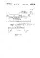
- FIG. 10(a)is a general block schematic diagram of the interleaved video field decoding system of the present invention.
- FIG. 10(b)is a block schematic diagram of the sync separation and system timing circuitry of the present invention.
- FIG. 10(c)is a block schematic diagram of an audio decoder according to one embodiment of the present invention.
- FIG. 10(d)is a block schematic diagram of the audio selector in accordance with the embodiment illustrated in FIG. 10(c);
- FIGS. 11(a) and (b)are graphs showing television vertical and horizontal sync intervals, respectively;
- FIG. 12is a block schematic diagram of an embodiment of a compressed audio encoder.
- FIG. 13is a block schematic diagram of an embodiment of a compressed audio decoder.
- FIG. 1(a)there is shown a portion of a conventional television signal within the blanking interval for horizontal retrace of the position of the electron beam in a cathode-ray display tube.
- the basic data cell according to the present inventionis the equivalent of one horizontal scan line or trace of an RS-170A composite video signal, as shown in FIG. 1(b).
- There may be several types of data involved in a data cell in the inventionincluding analog and audio data, several bits of serial digital data, analog video information with color modulation at 3.58 Mhz., and may include a mix of these types of information on horizontal scan lines within vertical blanking and non-vertical blanking portions of a video field.
- a logical accumulation of data cellsconstitutes a video field that contains 262.5 horizontal scan lines or traces of information sufficient for producing a displayable field on the cathode-ray display tube of a television receiver.
- the first horizontal scan lines or traces 1 through 9are reserved for vertical synchronization in conventional television signals, and lines 257 through 262 usually suffer degradations from skewed tape-recording servos, noise caused by switching of tape-recorder heads, and the like.
- the remaining intermediate 248 horizontal scan lines that form the central region of a displayable field(and, optionally, all horizontal scan lines) are available to include digital and audio signal information according to this invention in a manner which is compatible with existing NTSC requirements for horizontal line placement within the displayable field.
- FIG. 2(a)there is shown a graph of several conventional television waveforms within the vertical blanking interval. Color fields I and II are associated with color Frame A, and color fields III and IV are associated with color frame B. Of course, such signal waveforms continue through this sequence of 262.5 conventional scan lines or traces, as illustrated in FIG. 2(b).
- the present inventionintroduces audio information on all horizontal scans or traces of a video field in the one embodiment illustrated in FIG. 2(b) (or as compressed audio information on only a selected few horizontal scans or traces such as lines 10 and 11 in another embodiment).
- FIG. 2(b)shows how a standard NTSC video field is modified in accordance with the present invention.
- a video fieldcontains 2621/2 scan lines.
- the beginning of each and every scan linecontains an audio sync pulse 28 followed by a variable number of audio sample tracks 30.
- VCR head switchingwhich is normally at line 257 in the video field
- the purpose of the audio sync pulseis to locate the audio samples even during the period when the horizontal lines are skewed.
- lines 1 through 3 and lines 7 through 9contain equalizing pulses, and the vertical sync pulse occurs during lines 4 through 6.
- Lines 12 through 21contain header data, as illustrated in FIG. 2(c), which indicates the position of this field in a logical sequence of fields.
- the header datais also relevant to the program material, including the spacing of successive fields of the same program material. Additional data may be included in lines 22 through 256 in lieu of normal video.
- FIG. 2(c)illustrates the format for header data.
- Each linecontains two 8-bit bytes or one 16-bit word.
- Lines 12 and 13contain 4 bytes or two words of utility data which can be used to control program flow, synchronized with the current program material.
- Line 14is a tier identifier number that indicates which tier or program material this field is a member of.
- the first byte of line 15contains a tier field number. This is a sequential number beginning with 0 for the first field of a new tier or portion of program material. A value of 255 indicates the end of this tier or program material.
- the second byte of line 15contains a field type identifier. Field type has 256 possibilities and indicates the format of video versus digital data contained within this field.
- a type of 0indicates that lines 22 through 262 contain video information only. Other values indicate the type and location of digital data within the normal video period of lines 22 through 256. For example, a value of 1 may indicate that lines 22 through 256 contain digital data in the form of program header. A value of 2 may indicate that lines 2-256 contain digital data (not for display) which represents program logic.
- Line 16contains the byte check sum of lines 12 through 15. Lines 17 through 21 inclusively, may contain a duplicate of lines 12 through 16.
- FIG. 2(d)shows the format of a horizontal scan line used for digital data.
- a typical horizontal scan linebegins with the horizontal sync pulse, a colorburst and then, according to the present invention, an audio sync pulse followed by samples of audio tracks (in this case, four shown).
- an audio sync pulsefollowed by samples of audio tracks (in this case, four shown).
- a stream of 16 databitsoccurs at a point in the video area which is approximately 20 microseconds past the leading edge of the horizontal sync pulse.
- the width of each bitis approximately 1.4 microseconds.
- the value of 0is indicated by a video level below the 40% mark of black to white video, and the value of 1 is indicated by a level greater than 60% of the range between black and white.
- the 0.71 megahertz timing signal and the 89 kilohertz timing signalare both referenced to the leading edge of the horizontal sync pulse and are used to show the relative position of the databits with respect to these timing signals.
- FIG. 3(a)illustrates the scheme by which video material from several sources are combined and interleaved to form a video signal compatible with the present invention.
- field 1 of frame 1 of colorframe 1is presented as the first field.
- Field 2is selected from field 2 of frame 1 of colorframe 1 of video source 2.
- field 3 of video source number 3is selected for the third field.
- Field 4 of video source number 4is selected from the fourth field.
- the fifth fieldis selected from field 5 of video source number 1.
- Field 6is selected from video source N, and field 7 is selected from video source 1.
- the order in which video sources contribute to the resultant stream of video fieldsmay be fixed or variable according to the present invention. It should be noted, however, that each field in the resultant stream of video fields corresponds to the like numbered field of the tier or program source from which the video field is selected.
- FIG. 3(a)there is shown a pictorial illustration of video signals #1 through #N of displayable programs assembled into a selected sequence of video fields 6.
- Each of the video signals #1 through #Nmay be referred to for convenience as a ⁇ tier ⁇ and, as illustrated in FIG. 3(a), the selected video fields of the tiers (whether color, or black-and-white, or non-displayable data) are assembled in a sequence to form the composite multi-program (or multi-tier) video signal 6, according to the present invention.
- scene 1e.g. camera 1 providing one camera angle
- tiers 2, 3, nprovide scenes 2, 3, n, respectively.
- the video fields of tier 1are alternated in sequence with the video fields of tier 2 (and tier 3 and tier n) to produce the resulting composite signal 6, as illustrated in FIG. 3(a).
- the sequence of video fields selected from the tiers #1 through #Nmay be cyclic or according to an arbitrary sequence.
- Each video field associated with a tiermay correlate with the next video field in the sequence of that tier, so that the related video fields may be re-assembled during play-back and display according to the present invention as continuous portions of arbitrary length or duration of the initial tiers, as illustrated pictorially in FIG. 3(b).
- each video field 8includes header or identification information, which as previously descirbed, starts at line 10 and continues to line 21, for example in the following sequence:
- the tier identifier numberidentifies each of the initial tiers of displayable program material (up to 65,535), and the tier field number designates the field sequence in the designated tier, as illustrated in FIG. 3(a).
- the video field type identificationidentifies a normal video field from a digital video field, as previously described, since a digital video field will normally not be displayed. With the header information in place, the transfer rate of streamer data is 240 bytes per second, or about 1900 BAUD.
- Each video fieldcontains 2 bytes of data that indicate the tier number of which this field is a number to facilitate the skipping from field to successive field in a non-cyclic sequence for re-assembling the correlated, sequential video fields of a selectable tier, as illustrated in FIG.
- the interleave factor between video fieldsidentifies the distance (or interleaved number of video fields) between correlated video fields of the same tier and can be arbitrarily changed at any video field according to the needs of the current program material.
- the composite video signal 6includes successive fields cyclically assembled from the tiers #1 through #N, then simple iterative counting may be used to re-assemble successive fields of a selected tier without the need for header information. Frequent, non-cyclic selections of one tier over another tier, however, may be required to improve the visual display of rapid image movements in such one tier of program material, compared with slower image movements (for example, a scoreboard) in another tier of program material.
- the typical tier of program materialis a displayable video scene of moving objects. In order to maintain reasonably acceptable display of motion, it is believed that compilation of four tiers of program material is a subjective limit, although many more tiers are possible according to the present invention.
- the present inventionalso accommodates data tiers which can transfer digital data (normally not for display but for control or other purposes) at the rate of approximately 28K bytes per second.
- the composite video signal 6, as illustrated in FIG. 3(a)may therefore be selectably and interactively reassembled into portions 10, 12, 14, 16 of arbitrary duration of the original tiers of successive video fields, as illustrated in FIG. 3(b).
- the composite signal illustrated in FIG. 3(a)may occur in real time, for example, for cable transmission or be recorded on, for reproduction from, a recording medium such as conventional video disks or video cassette recording tape.
- FIG. 4there is shown a pictorial representation of the composite signal for multi-program material compiled on video tape 9.
- the traces 11include scan synchronizing information and field header information, as previously described, for proper operation of decoding equipment, later described herein.
- the video field tracesare interleaved along the length of the tape (i.e.
- the correlated video fields that comprise one complete programmay therefore be reconstructed in accordance with one embodiment of the invention by using every fourth trace in the sequence, while each of the other complete programs may be reconstructed using every fourth trace displaced by one or two or three traces, respectively.
- each of the other complete programsmay be reconstructed using every fourth trace displaced by one or two or three traces, respectively.
- program materials including rapidly moving imagesmay include higher density of successive fields of information (i.e. greater number of fields per unit time) in non-cyclical distribution in the composite signal to reduce the delay time between updates of fixed-field displays to thereby reduce the jerky or stroboscopic appearance of moving images being displayed.
- composite signalneed not be assembled on a video tape, as illustrated in FIG. 4, but may be assembled and transmitted in real time, for example, via cable television network, with successive fields of multiple programs interleaved in cyclic or non-cyclic succession, as previously described.
- each video field of informationincludes the header data or coded signals previously described to designate the correlated or associated program material and the field number in the succession of video fields for that program.
- each video fieldincludes audio signal that are introduced into the horizontal scans or traces of each video field in various ways according to alterative embodiments of the present invention.
- the initial portion of the video waveform that follows the horizontal synchronizing pulse 16 by a selected time interval 18includes four distinct timed intervals 20 (for four tracks of audio programs) preceded by an audio synchronizing pulse 22.
- each of the four timed intervals occurring in the interval 20 that follows the audio sync pulse 22individual samples of analog audio signals for each audio signal channel are imposed on the video intensity level at the start of the horizontal scan or trace. Since this initial sector of the horizontal trace is normally not displayed, the audio signals imposed on the video intensity levels according to this embodiment of the present invention does not significantly alter compatibility with standard NTSC television waveforms.
- a greater number than four independent audio channelstends to extend the audio-samples interval 20 into visible, displayable portions of horizontal traces 22 through 256, and may therefore require masking to prevent their appearance on the television display screen.
- audio signal informationmay be selectively introduced into the horizontal traces of a video field by allocating, say, horizontal scan or trace lines 10 and 11 for compressed audio signalling.
- the individual channels of audio informationare compressed into the video interval of horizontal trace line 10, or line 11, or both, as illustrated in FIG. 1(b), for high-speed transfer into a buffer register.
- the buffer registercan be clocked at low speed to yield the slow-speed stream of audio signal samples over the time interval until horizontal scan line 10 next appears in the next video field.
- Audio signals introduced into video fields of displayable programsremain compatible with standard NTSC television waveforms, and additional audio channels can be readily introduced with higher speed transfers of audio samples into buffer registers, or with additional horizontal scan lines allocated for compressed audio signalling.
- audio information correlated with all tiers of displayable programsis included in each video field of each tier.
- the on-going audio signal information correlated with any one tieris always available from the video fields of such one or other tiers, even though the video fields for such one tier may be infrequently sampled (for example, to display a scoreboard with continuing background music).
- FIGS. 5 and 6there are shown simplified block schematic diagrams of apparatus according to one embodiment for producing the composite video field signal 6 for multi-tier or multi-program interactive operation on multiple video inputs 24.
- the video inputs 24are illustrated to be derived from multiple sources 13, 15, 17, 19 of program material (such as video tape recorders or video cameras). Each source is connected via conventional time-base correctors 21, 23, 25, and 27 to a video encoder 29 which produces the composite video signal 6 by interleaving the selected video fields from the multiple program sources.
- the interval encoder 37generally introduces header data on the composite video signal under control of a computer or processor 39, and the audio encoder 41 that follows generally introduces audio information correlated with the multiple programs into the video field output information 43.
- the multiple program sources 13-19e.g. video tape recorders or video cameras
- the synchronization generator 31assure that the program sources 13-19 operate in synchronism to provide individual video field inputs 24 from the multiple program sources 13-19 that are synchronized in time, as illustrated in FIG. 3(a).
- Auxiliary video information 35for example, background scenery that is normally intended to be updated only over long intervals, or filler scenes for display during transitions between program sources, may also be supplied to the video encoder 29.
- a minicomputer or microprocessor 33is connected to control the signal sources with respect to time codes (such as status and position information that are associated with the fields of taped program materials).
- the computer 33thus controls the encoder 29 which may be a conventional video switch to select particular, successive fields of selected program sources in accordance with an edit decision list, later described herein, to produce a composite video signal 6, as previously described in connection with FIG. 3(a).
- the selection of particular video fields at the inputs 24 from the program sources 13-19can be made at every video field by the computer 33 in accordance with this edit decision list (e.g. a look-up table in software) that follows the synchronized time line that is common to the program sources.
- this edit decision liste.g. a look-up table in software
- the exact timing for the switchingis determined by the synchronizing clock 45 that received sync input from the synchronization generator 31, which, in turn, may derive its synchronization from the reference subcarrier information (i.e. standard SCH timing signals), as illustrated in FIG. 2(a).
- the video input gating or switching 47under exact timing control of the clock 45 selects color field I from video source 1, color field II from video source 2, color field III from video source 3, color field IV from video source 4, and so on.
- Control by computer 33may not be required in this cyclic example to achieve a succession of video fields in the composite video signal 6, but is required to achieve non-cyclic, dynamically-controllable succession of video fields selected in arbitrary sequence, as shown in FIG. 3(a), from the video inputs.
- FIG. 8there is shown a block schematic diagram of an interval encoder 37 that is arranged to place all of the header and digital data in the correct locations in each video field in the composite video signal 6.
- the header datamust be issued according to the timeline which is the standard SMPTE timecode input 50 to the time code reader 51.
- This time code inputis derived from a master controller such as computer 33 or from a master tape recorder, or the like.
- the computer 39is activated by the time code reader to supply control data 53 to the level shifting buffer 55 of the interval encoder 37.
- This buffer 55changes the signal levels to video-compatible levels and interposes the data 57 on the correct horizontal scan line or trace of the current video field.
- the timing for interposing the header and other digital data at proper video signal levelsis under control of the timing generator 59 that supplies synchronizing pulses 61 derived from the current video field or, optionally, from an external timing signal in a manner similar to the operation of the video encoder previously described in connection with FIG. 7.
- FIG. 9there is shown a block schematic diagram of the audio encoder 41 which is connected to receive the composite video signal (with header and digital data included) from the interval encoder 37.
- This encoderis similar in features and operation to the video and interval encoders previously described herein, and is configured generally to interpose the audio signal information in the current video field with the proper timing and signal levels.
- the audio encoder 41accepts (N) number of audio signal inputs (which may be correlated with N number of tiers of displayable programs) for processing and placement in the current video field according to either embodiment of the invention previously described.
- Converter 63thus receives the audio inputs and the video timing signals from the timing clock 65 (derived from the current video field or from an external timing source) to supply the requisite audio signal information for the current video field.
- the converter 63is configured in conventional manner to supply an audio sync pulse 22 followed by a sample pulse per individual audio signal channel for interposing 67 on substantially each of 262 horizontal scan lines of the current video field.
- the converter 63is configured in conventional manner to sample and compress approximately 1/60 of a second of audio signal information from each audio input 61 for interposing 67 on, say, the tenth horizontal scan line, or other line or lines, of each video field in the video input 40 an assembled, high-speed stream of compressed audio samples, as later described herein.
- the present inventionproduces a composite video signal which includes a sequence of video fields assembled by cyclic or non-cyclic selection of selected, successive fields of multiple displayable programs. Header and other data and audio signal information are interposed on the video fields to provide program and field designations useful in detecting and re-assembling successive video fields, with associated audio signals, that are correlated with a selected displayable program.
- classes of real-time programminge.g. multiple camera angles of the same sports event
- classes of displayable program materialsuch as tutorial or game-oriented products may require editing or pre-selection functions in order to assemble an optimal, interactive displayable product.
- An edit control listis compiled of the sequences that are correctly workable in acceptable sequences, and such edit control list forms the basis for a look-up table that resides in the computer 39 to impose limitations upon the interval coding that may be introduced into each designated program and video field designation.
- the audio signals which correlate with the multi-tier programscan be stored on separate tape tracks for synchronized introduction into the edited version of a master tape of the selectable video fields, and normal audio signals may also then be recorded on the master tape in accordance with NTSC and RS-170 standards for television signals.
- editing program materialwill be edited in the present invention in the manner similar to conventional video production.
- editing program material according to the present inventionmay require displaying the sequence of interleaved video fields with and without interval-encoded interactions.
- the header data including interval codesthus provide the code information for the interactive recovery of the original tier information along a timeline.
- a master tape that stores a multi-tier, interleaved composite signal of video fieldswill begin with a standard timecode (by Hours: Minutes: Seconds: Frames), and will continue with successive timecodes representative of every change in pattern or data, as illustrated in the following example:
- Every timecode associated with a change in pattern or datamay be stored in a database, down to the smallest duration (i.e. one field).
- the preceding examplesidentify four events by their start timecode numbers and their ending timecode numbers, listing the changes with descriptions of the events.
- the timecodemay be used effectively for controlling operation of multi-tier interleaved program material.
- the timecode for blackburst signalhas no header data, and a decoder unit that is arranged to receive the program material will normally wait for a valid header.
- a selected first display screenmay thus have a header that designates a logo as tier zero (0) which the playback decoder will hold or freeze on display while digital data in successive video fields (not for display) in the form of executable object code may be downloaded to a decoder.
- the initial transfer or downloading of datamay include an initialization routine for the decoder.
- Second and subsequent transfersmay be of data and programs to determine how designated tiers and fields throughout the program may interact.
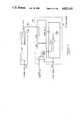
- FIG. 10(a)there is shown a block schematic diagram of one embodiment of decoder or playback apparatus 71 according to the present invention.
- Central processor 73is connected to controllers 73 and to sync separator and system timing device 79, and to field store 81 and to the 8-bit shift register 83 at the output of video detector 85, and to the audio selector 87, and to the audio synthesizer 89.
- the central processor 73is a Z-80 microprocessor with 8 kilobytes of RAM and 8 kilobytes of ROM.
- Video 91 in the form of composite NTSC signals from a standard video cassette recorder 93enters the decoder apparatus 71 through a jack so provided.
- the incoming video signal 91is simultaneously applied to the input of the field store 79, the audio decoder 95, the video detector 85 and the sync separator and system timing device 77.
- the field store 79captures on a field-by-field basis the contents of video pictures that come off a VCR tape of the type described in connection with FIG. 4 and played through the VCR 93.
- Timing and control signalsare provided to the field store 79 from the sync separator and timing system 77 in the form of 7.1 megahertz oscillations and vertical sync, and 30 hertz reference signals.
- Controlis also provided from the central processor 73 to the field store 79 to control whether the field store shall currently sample a new video image or play back a previously sampled video image.
- the field store 79thus operates in a sample mode or hold mode. In a sample mode it samples a new video signal, the timing of which is controlled by the 7.1 megahertz, and vertical sync and 30 hertz signals. In the hold mode, those same signals are used to play back a previously stored field at the same rate at which it was recorded.
- the output of the field store 79is applied to the video section of the RF modulator 97 which modulates the stored video field for reception on channel 3 or 4.
- This modulated signal 99becomes input to a standard television set 101.
- the input 91 from the VCR 93is also applied to the sync separator and system timing block 77 which breaks out the synchronizing signals of the composite video signal 91 and makes them available for operation within the decoder 71.
- the vertical sync signalis applied to the field store 79, and the burst gate (which is a synchronizing pulse timed from the video input) is applied to the audio decoder 95, and a 60 hertz input is applied to the central processor 73.
- the 60 hertz signal applied to the central processor 73gives the central processor a timing mark to designate when new fields of video occur so that the processor can make the decision whether to sample a new field or continue to hold a previously sampled field.
- the central processor 73also uses the 3.6 megahertz signal that comes from the system timing block 77 as the basic system clock for the Z80 processor.
- the central processor 73also relies upon the composite synchronizing signal from the sync separator block 77 in order to synchronize with the beginning of each horizontal scan line in a field.
- the central processor 73coordinates and handles the downloading of digital program data that may be stored on the tape. Such data may be available at each horizontal scan line where digital data is present, and the composite sync provides an indication to the central processor 73 of the beginning of a scan line so that the central processor 73 can synchronize its download function.
- the sync separator and timing system block 77provides 14.3 megahertz and a burst gate signal to the audio decoder 95.
- the 14.3 megahertzis used for timing within the audio decoder in order to locate audio data that was previously encoded into the video portion of horizontal scan lines of various fields in a manner compatible with the NTSC signal standards.
- the burst gate signalis used to locate the beginning of each scan line which contains audio data.
- the sync separator and timing system block 77provides an 89 kilohertz signal which acts as a data-byte-ready indicator to the central processor 73 for the downloading of data.
- This data byte ready signalindicates that 8 bits of downloadable data had been shifted into the shift register 83 and that a byte, or 8 bits of data, is now available to the central processor 73.
- the datais shifted into the shift register at the rate of 0.71 megahertz or 710 kilohertz, a signal which is also provided by the sync separator and system timing block 77.
- the video detector 85which is basically a comparator, looks for a video level above a certain threshold value. Video above that threshold value is taken as a binary 1 and video below that level is taken as a binary 0.
- the video detector 85thus makes a decision based upon the luminence level of the video signal at a particular point on the scan line whether there is a 0 or a 1 binary value at that location. That value is then shifted into the 8-bit shift register 83 at each 710 kilohertz sample point.
- an indicationis supplied to the central processor 73 from the sync separator and timing system timing block 77 to indicate that 8 bits have been shifted in, and that the central processor 73 should accept the 8 bits of data to allow the cycle to begin again. There are two bytes of data accepted during each horizontal scan line.
- the audio decoder 95decodes audio which has been encoded into the video portion of each horizontal scan line. Multiple samples from various audio tracks may be so encoded on each horizontal scan according to one embodiment of the invention, and the audio decoder 95 will decode up to 4 audio tracks placed side by side at intervals of the 3.58 megahertz signal. The 4 tracks so decoded by the audio decoder are then applied to the audio selector 87 and the control lines 103 thereto from the central processor 73 determine which particular combination of the 4 audio tracks is to be combined to form one composite audio track. The selected audio track is then fed into an audio mixer 105. The audio mixer combines the decoded audio track with the output of a sound-effects audio synthesizer 107 which is also under control of the central processor 73.
- the output of the sound-effects audio synthesizer 107is mixed by the audio mixer with the combination of selected tracks to provide a mixed audio output which is then applied to the RF modulator 97 where (like the video) it is modulated up for reception on channels 3 or 4 as part of the RF signal 99 in the standard VHF television range of channels 3 or 4 for playback on a standard television set 101.
- the controllers 75represent a matrix of pushbuttons, including pushbuttons numbered 1-12, an action button and a freeze button.
- the controllers 75encode the buttons in such a way that each button has a unique 4-bit binary code.
- These 4-bit binary codesare applied to the central processor 73 as operator inputs to control interaction with the displayable video fields.
- the particular sequence of video fields controlled by the operator using controllers 75may also be recorded on a standard video tape recorder connected to receive the modulated video output 99 as a mode of preserving the individually-edited multi-tier program material.
- the field store circuit 79is similar to the frame-freezing buffer circuit available in the commercial DX3 digital video cassette recorders produced by Toshiba Corporation, and the audio synthesizer 107 is a commercially available integrated circuit type AY3 8910 produced by General Instruments.
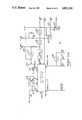
- FIG. 10(b)there is shown a block schematic diagram of the sync separator and system timing block 77 of FIG. 10(a).
- a standard integrated circuit 110(type MC 1378 produced by Motorola Corporation) is connected through a capacitor 111 to receive the incoming video 91 at pin 24, for example, from the standard video cassette recorder 93 of FIG. 10(a).
- An external tank circuit 113is connected between pins 32 and 33 to form a 14.3 megahertz oscillator (i.e. tuned to a frequency which is four times higher than the basic NTSC standard color-carrier frequency). This 14.3 megahertz signal is available on pin 35 to be amplified, divided and shaped as required, and is applied to the audio decoder 95 of FIG. 10(a).
- the 14.3 megahertz signalis divided by divider 115 and shaped by pulse shaper 117 into a pulse of 5 microsecond width for application to pin 40 as the horizontal input timing pulse.
- Thisforms a phase-locked loop that synchronizes the 14.3 megahertz signal with standard 63.5 microsecond horizontal scan lines.
- exactly 910 cycles of the 14.3 megahertz signaloccurs in the interval of each horizontal scan line.
- the 14.3 megahertz signal produced by the integrated circuit 110is divided by 2 in divider 119 and shaped substantially to a sinewave in network 121 for application to the field store circuit 79 of FIG. 10(a).
- the 7.1 megahertz signal from divider 119is further divided by 2 in divider 123 to provide the 3.58 megahertz signal that is applied as the basic clock signal to the central processor 73 of FIG. 10(a).
- the vertical sync signalappears at pin 30 of the integrated circuit 110 approximately 60 times per second, and this signal is also applied to the central processor 73 at FIG. 10(a) to assure that changes in selected video fields can occur in synchronized, timely, manner.
- These vertical sync signals(and the divided-by-two version available at the output of divider 125) are supplied to the field store 79 of FIG. 10(a) to assure synchronized field storing operation on the beginning of a selected video field.
- the 7.1 megahertz signal at the output of divider 119is also divided by 10 in scale-of-ten divider 127 to provide the 710 kilohertz output signal 131 that is supplied to the 8-bit shift register 83 of FIG. 10(a) as the bit-shifting clocking frequency for down loading data from incoming video signal 91, as previously described.
- the 710 kilohertz signalis further divided by 8 in the scale-of-eight divider 133 to supply 89 kilohertz signal to the central processor 73 of FIG. (10)a as a synchronized indication that 8-bits of data have been shifted into this register 83 and are ready for downloading to the processor 73, as previously described herein.
- dividers 127 and 129may be scaler counters which are reset to zero by the horizontal sync signal at the output of divider 115. All frequencies described herein are referred to by nominal values, but it should be understood that exact multiple values are actually present in the operation of the present invention.
- FIG. 10(c)there is shown a block schematic diagram of the audio decoder 95 of FIG. 10(a).
- This circuitincludes 8 flip-flops 137-151 and a conventional analog switch 153 (for example, type 40HC66 integrated circuit).
- the flip-flops 137, 139, 141, 143, 145, 147are initially cleared to the zero state.
- the 14.3 megahertz signal previously describedis applied to flip-flop 149 which divides the frequency by two for application to flip flop 151 which again divides the frequency by two for application as a 3.58 megahertz signal 152 to the clock inputs of flip-flops 141, 143, 145 and 147.
- flip flopsare configured as a shift register of the type in which data applied to the D input 155 of flip flop 141 is sequentially transferred to the next flip-flop in succession at the leading edge of each applied clock signal 152.
- D input 157 of flip-flop 137is connected to receive +5 volts, that flip-flop 137 also triggers a ⁇ 1 ⁇ output 161 in response to the leading edge of the burst gate signal 159 that is applied to the clock input of flip-flop 137.
- the ⁇ 1 ⁇ output 161 from flip-flop 137transfers to the D input of flip-flop 139 and also deactuates its ⁇ clear ⁇ input 163.
- the next video signal 165 of sufficient level to be detected as a ⁇ 1 ⁇(i.e. detecting video white level), and applied to the preset input of flip flop 139, sets the flip flop. This, in turn, supplies a ⁇ 1 ⁇ output to D input of the first flip flop 141 in the shift register configuration.
- the combination of flip flop 37 being set and flip flop 139 being resetprovides two low-enable signals to the gate 167, the output of which is inverted and provides a preset to flip flops 149 and 151.
- These flip flopsare configured as a divide-by-4 counter.
- the combination of flip flop 137 being set and flip flop 133 being resethas the effect of holding flip-flops 149 and 151 at a count of 3 during the time between when the leading edge of the burst gate appears and when video white level is detected.
- the very next cycle of 14.3 megahertz signal 169resets both flip flops 149 and 151 from their 3 count value to a 0 count equivalent value.
- Thisprovides a ⁇ 1 ⁇ pulse that is clocked into flip flop 141.
- Thiscauses a ⁇ 1 ⁇ output from flip-flop 141 which is supplied to flip flop 137.
- the clearing of flip flop 137causes flip flop 133 to be cleared, thus removing the ⁇ 1 ⁇ input to the D input of flip flop 141 as the single value that will be gated into the shift register comprising flip flops 141-147. Since the clocks of flip flop 141-147 are supplied by the output of flip flop 151 (i.e. the last stage of the divide-by-4-counter), the net effect is that ⁇ 1 ⁇ is shifted into flip flop 141 and through the succeeding flip flops 143, 145 and 147 at the 3.58 megahertz rate.
- each of those flip flopsin turn presents the ⁇ 1 ⁇ signal to the four inputs 172 of the four stages of analog switch 153.
- the inputs 173 to the analog switchare also connected to the video-in line 175 so that when each stage in succession is turned on, each of the outputs seizes a sample of the video input for 280 nanoseconds sample width.
- the samplesare stored in the capacitors 177 which are connected to the respective audio track outputs 179.
- the sample-and-hold effect of the switches 153 and capacitors 177 per audio trackallows the recovery of the audio signals from those samples at the specific locations immediately following detection of the video white level, as shown in FIG. 2(d).
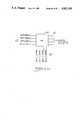
- FIG. 10(d)there is shown a block diagram of the audio selector 87 which is connected to receive the four audio-track outputs 179 from the audio decoder 172 of FIG. 10(c).
- any combination of the four control lines 181 that lead into the analog switch 183 of conventional integrated circuit configurationmay be enabled or disabled to pass any combination of audio track 1-4 through the switch 183 to constitute the selected audio tracks for application to the audio mixer 105 of FIG. 10(a).
- FIGS. 11(a) and (b)there are shown graphs of the vertical and horizontal sync pulses which are the bases for operation of the compressed audio embodiment of the present invention.
- the compression and expansion of the audio signalsis controlled with respect to timing signals derived from the video fields in which it is inserted, or from which it is retrieved.
- the audio signals in the time domain of the vertical sync pulse interval, FIG. 11(a)is compressed to fit within the time domain of the horizontal sync pulse interval FIG. 11(b).
- the video circuitry preceding the audio compression encoderrecovers the color subcarrier and creates a master clock of 14.3 megahertz.
- a frequency at half the master clock frequency, or 7.16 megahertz and a frequency of one 637th of the master clock frequencyare derived from the master clock.
- a color lock and sync separator circuit 191 of conventional designextracts horizontal and vertical timing signals 193, 195 from the video input 6.
- the start bits 197constitute a full "white” level video signal for a logical ⁇ 1 ⁇ and the next bit is a "black" level video signal for a logical ⁇ 0 ⁇ .
- the master clock frequencyis divided by 637 and by 2 to provide the control frequencies 199 and 201, along with horizontal line count 203, to the clocking selection logic 205.
- An analog shift register 207 of conventional designis normally operable as a delay line to delay a line of video for possible restoration or replacement of a "dropped out" line of video in a video cassette recorder, or the like.
- audio signal in the time span of the duration of one video fieldis compressed in the analog shift register 207 into the time span of one horizontal scan or trace of a video field.
- there are two 455-sample registersand one such register can be clocked at 7.16 megahertz to receive or produce 455 samples in the time interval of one horizontal scan.
- the resulting audio compression ratio of 318.5is selected because 375 samples can be clocked in at 1/637the of the master clock frequency in about 53 microseconds, or about the usable time interval of one horizontal scan.
- the audio input 209can be clocked into the shift register 207 at about 22,477.5 hertz (i.e. about 11 kilohertz bandwidth), commencing with the start bits 197, for 375 successive samples.
- a quick burst of 80 clock pulsesfills the 455-sample register and produces the first audio sample at the output 211 for placement in the video signal in a manner similar to that which was previously described in connection with FIGS 5-9.
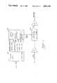
- FIG. 13there is shown a block schematic diagram of a decoder according to an embodiment of the present invention.
- similar conventional circuitsoperate in the manner previously described to derive the required timing signals from the video input 43 (with compressed audio) for application to the clocking selection logic 206.
- the video input 43(with compressed audio) is applied to the analog shift register 208 which is controlled by the clocking selection register 206 to fill the register with the compressed audio samples, commencing with the ⁇ 1 ⁇ - ⁇ 0 ⁇ start bits and continuing for one horizontl scan interval, and thereafter to clock out the stored samples at the rate of 22,477.5 hertz into conventional filter and amplifier 215 to provide the real-time audio output 217.
Landscapes
- Engineering & Computer Science (AREA)
- Multimedia (AREA)
- Signal Processing (AREA)
- General Engineering & Computer Science (AREA)
- Television Signal Processing For Recording (AREA)
- Television Systems (AREA)
Abstract
Description
______________________________________ 00: 00: 00: 00-00: 01: 00: 00 = normal blackburst signal; 00: 01: 00: 01-00: 01: 01: 00 = Color logo be held for 1 minute; 00: 01: 02: 00-00: 02: 00: 00 = copy protection and main data; 00: 02: 00: 01-**: **: **: ** = tutorial or game program; ______________________________________
Claims (11)
Priority Applications (7)
| Application Number | Priority Date | Filing Date | Title |
|---|---|---|---|
| US07/016,671US4821101A (en) | 1987-02-19 | 1987-02-19 | Video system, method and apparatus |
| US07/152,423US4849817A (en) | 1987-02-19 | 1988-02-04 | Video system, method and apparatus for incorporating audio or data in video scan intervals |
| CA000558150ACA1331054C (en) | 1987-02-19 | 1988-02-04 | Video system, method and apparatus |
| EP88102239AEP0279411B1 (en) | 1987-02-19 | 1988-02-16 | Method and apparatus for forming multi-program video signals |
| AU11742/88AAU1174288A (en) | 1987-02-19 | 1988-02-16 | Viewer selectable interleaved real-time video program transmission |
| JP63037295AJPS63226182A (en) | 1987-02-19 | 1988-02-19 | Video recording system, method and apparatus |
| AU29639/89AAU2963989A (en) | 1987-02-19 | 1989-02-03 | Interleaved real-time viewer-selectable multi-program television system |
Applications Claiming Priority (1)
| Application Number | Priority Date | Filing Date | Title |
|---|---|---|---|
| US07/016,671US4821101A (en) | 1987-02-19 | 1987-02-19 | Video system, method and apparatus |
Related Child Applications (1)
| Application Number | Title | Priority Date | Filing Date |
|---|---|---|---|
| US07/152,423Continuation-In-PartUS4849817A (en) | 1987-02-19 | 1988-02-04 | Video system, method and apparatus for incorporating audio or data in video scan intervals |
Publications (1)
| Publication Number | Publication Date |
|---|---|
| US4821101Atrue US4821101A (en) | 1989-04-11 |
Family
ID=21778328
Family Applications (1)
| Application Number | Title | Priority Date | Filing Date |
|---|---|---|---|
| US07/016,671Expired - Fee RelatedUS4821101A (en) | 1987-02-19 | 1987-02-19 | Video system, method and apparatus |
Country Status (5)
| Country | Link |
|---|---|
| US (1) | US4821101A (en) |
| EP (1) | EP0279411B1 (en) |
| JP (1) | JPS63226182A (en) |
| AU (1) | AU1174288A (en) |
| CA (1) | CA1331054C (en) |
Cited By (33)
| Publication number | Priority date | Publication date | Assignee | Title |
|---|---|---|---|---|
| US4903129A (en)* | 1989-04-06 | 1990-02-20 | Thomson Consumer Electronics, Inc. | Audio signal section apparatus |
| WO1991003112A1 (en)* | 1989-08-23 | 1991-03-07 | Delta Beta Pty. Ltd. | Program transmission optimisation |
| US5018013A (en)* | 1989-12-21 | 1991-05-21 | Zenith Electronics Corporation | Programmable audio/video signal interface |
| US5055924A (en)* | 1989-01-21 | 1991-10-08 | Gfk Gmbh | Remote-controlled substitution of a defined program part of a tv program by a separately transmitted program part for defined, selected receivers, household terminal for executing the method and method for operating a household terminal |
| US5331417A (en)* | 1992-09-15 | 1994-07-19 | Digital Pictures, Inc. | System and method of displaying a plurality of digital video images |
| US5420801A (en)* | 1992-11-13 | 1995-05-30 | International Business Machines Corporation | System and method for synchronization of multimedia streams |
| US5421031A (en)* | 1989-08-23 | 1995-05-30 | Delta Beta Pty. Ltd. | Program transmission optimisation |
| US5469221A (en)* | 1988-07-13 | 1995-11-21 | Seiko Epson Corporation | Video multiplexing system for superimposition of scalable video data streams upon a background video data stream |
| US5537141A (en)* | 1994-04-15 | 1996-07-16 | Actv, Inc. | Distance learning system providing individual television participation, audio responses and memory for every student |
| US5539471A (en)* | 1994-05-03 | 1996-07-23 | Microsoft Corporation | System and method for inserting and recovering an add-on data signal for transmission with a video signal |
| US5555193A (en)* | 1993-05-25 | 1996-09-10 | Kabushiki Kaisha Toshiba | Video compression system with editing flag |
| US5621471A (en)* | 1994-05-03 | 1997-04-15 | Microsoft Corporation | System and method for inserting and recovering an add-on data signal for transmission with a video signal |
| US5632007A (en)* | 1994-09-23 | 1997-05-20 | Actv, Inc. | Interactive system and method for offering expert based interactive programs |
| US5682196A (en) | 1995-06-22 | 1997-10-28 | Actv, Inc. | Three-dimensional (3D) video presentation system providing interactive 3D presentation with personalized audio responses for multiple viewers |
| US5724091A (en) | 1991-11-25 | 1998-03-03 | Actv, Inc. | Compressed digital data interactive program system |
| US5796440A (en)* | 1996-02-29 | 1998-08-18 | Rupinski; Frederick A. | Baseband video/audio/data transceiver |
| US5929870A (en)* | 1988-07-13 | 1999-07-27 | Seiko Epson Corporation | Video multiplexing system for superimposition of scalable video data streams upon a background video data stream |
| US20010013123A1 (en)* | 1991-11-25 | 2001-08-09 | Freeman Michael J. | Customized program creation by splicing server based video, audio, or graphical segments |
| US6321208B1 (en) | 1995-04-19 | 2001-11-20 | Brightstreet.Com, Inc. | Method and system for electronic distribution of product redemption coupons |
| US20020194589A1 (en)* | 2001-05-08 | 2002-12-19 | Cristofalo Michael | Technique for optimizing the delivery of advertisements and other programming segments by making bandwidth tradeoffs |
| US20030058707A1 (en)* | 2001-09-12 | 2003-03-27 | Dilger Bruce C. | System and process for implementing commercial breaks in programming |
| US20030219081A1 (en)* | 2002-05-21 | 2003-11-27 | Sheehan Patrick M. | System and method for providing private in-band data to digital set-top boxes in a broadcast environment |
| WO2003091936A3 (en)* | 2002-04-26 | 2004-01-22 | Ds Usa Inc | Increasing the play time of a cd |
| US20040064497A1 (en)* | 1992-04-02 | 2004-04-01 | Delta Beta Pty. Ltd. | Method and system of program transmission optimization using a redundant transmission sequence |
| US6847373B1 (en) | 1999-04-16 | 2005-01-25 | Avid Technology, Inc. | Natural color matching in a video editing system |
| US7079176B1 (en) | 1991-11-25 | 2006-07-18 | Actv, Inc. | Digital interactive system for providing full interactivity with live programming events |
| US7305691B2 (en) | 2001-05-07 | 2007-12-04 | Actv, Inc. | System and method for providing targeted programming outside of the home |
| US7401032B1 (en) | 1995-07-25 | 2008-07-15 | News America Marketing Properties | Process for the distribution and redemption of coupons |
| US7448063B2 (en) | 1991-11-25 | 2008-11-04 | Actv, Inc. | Digital interactive system for providing full interactivity with live programming events |
| US8092307B2 (en) | 1996-11-14 | 2012-01-10 | Bally Gaming International, Inc. | Network gaming system |
| US8473342B1 (en) | 2000-04-05 | 2013-06-25 | Catalina Marketing Corporation | Method and system for generating certificates having unique Id data |
| US8626581B2 (en) | 1995-06-16 | 2014-01-07 | Catalina Marketing Corporation | Virtual couponing method and apparatus for use with consumer kiosk |
| US8775245B2 (en) | 2010-02-11 | 2014-07-08 | News America Marketing Properties, Llc | Secure coupon distribution |
Families Citing this family (7)
| Publication number | Priority date | Publication date | Assignee | Title |
|---|---|---|---|---|
| US4849817A (en)* | 1987-02-19 | 1989-07-18 | Isix, Inc. | Video system, method and apparatus for incorporating audio or data in video scan intervals |
| JP2840755B2 (en)* | 1989-04-27 | 1998-12-24 | ソニー株式会社 | Program sending device |
| GB2238926A (en)* | 1989-12-07 | 1991-06-12 | Secretary Of The State For Def | Video multiplexer for surveillance installation |
| JPH0689549A (en)* | 1992-09-08 | 1994-03-29 | Pioneer Electron Corp | Device for reproducing and displaying image and recording medium |
| JP3219860B2 (en)* | 1992-09-11 | 2001-10-15 | パイオニア株式会社 | Video game equipment |
| EP0609054A3 (en)* | 1993-01-25 | 1996-04-03 | Matsushita Electric Industrial Co Ltd | Method and apparatus for recording or reproducing video data on or from storage media. |
| US5506932A (en)* | 1993-04-16 | 1996-04-09 | Data Translation, Inc. | Synchronizing digital audio to digital video |
Citations (48)
| Publication number | Priority date | Publication date | Assignee | Title |
|---|---|---|---|---|
| US2681383A (en)* | 1951-04-13 | 1954-06-15 | Zenith Radio Corp | Television receiver |
| US3051777A (en)* | 1955-06-14 | 1962-08-28 | Jerome H Lemelson | Magnetic recording systems |
| US3061669A (en)* | 1959-11-23 | 1962-10-30 | Nathaniel L Leek | Multiplex television system |
| US3202764A (en)* | 1953-09-22 | 1965-08-24 | Itt | Transmission systems |
| US3391247A (en)* | 1964-01-03 | 1968-07-02 | Minnesota Mining & Mfg | Television signal recording with sampled audio recorded during horizontal intervals |
| US3488435A (en)* | 1965-07-29 | 1970-01-06 | Bell Telephone Labor Inc | Time-division multiplex system wherein a vidicon is used for frame storage of video signals |
| US3493674A (en)* | 1965-05-28 | 1970-02-03 | Rca Corp | Television message system for transmitting auxiliary information during the vertical blanking interval of each television field |
| US3580998A (en)* | 1968-12-18 | 1971-05-25 | Diebold Inc | Video multiplexer-switcher with sequence recycling upon loss of video |
| US3586767A (en)* | 1968-04-04 | 1971-06-22 | Data Plex Systems | Reconstructable television transmission system |
| US3637926A (en)* | 1968-10-02 | 1972-01-25 | Data Plex Systems | System for transmitting two classes of superimposed information |
| US3697675A (en)* | 1970-12-23 | 1972-10-10 | Terry D Beard | Stereoscopic television system |
| US3700793A (en)* | 1970-06-09 | 1972-10-24 | Bell Telephone Labor Inc | Frequency interleaved video multiplex system |
| US3725571A (en)* | 1971-06-21 | 1973-04-03 | Westinghouse Electric Corp | Multiplex video transmission system |
| US3740465A (en)* | 1971-06-14 | 1973-06-19 | Rca Corp | Television frame storage apparatus |
| US3743767A (en)* | 1971-10-04 | 1973-07-03 | Univ Illinois | Transmitter and receiver for the transmission of digital data over standard television channels |
| US3745242A (en)* | 1971-05-17 | 1973-07-10 | Westinghouse Electric Corp | Multiplex tv system for transmitting and receiving a plurality of pictures on a line sharing basis |
| US3746780A (en)* | 1971-02-25 | 1973-07-17 | Mitre Corp | Video display system |
| US3751595A (en)* | 1970-03-09 | 1973-08-07 | Minnesota Mining & Mfg | Time sharing subscriber communications system |
| US3889063A (en)* | 1971-08-19 | 1975-06-10 | Phonplex Corp | Multiplexed digital data communication system |
| US3896487A (en)* | 1973-08-01 | 1975-07-22 | Tesler Vladimir E | Compatible stereoscopic color television system |
| US3902007A (en)* | 1973-06-26 | 1975-08-26 | Westinghouse Electric Corp | Audio and video plural source time division multiplex for an educational tv system |
| GB1420106A (en)* | 1973-01-18 | 1976-01-07 | Nippon Steel Corp | Method of multiplex recording of multichannel data signals with a vidio signal and of regenerating such record and apparatus therefor |
| US3991266A (en)* | 1974-09-03 | 1976-11-09 | Sanders Associates, Inc. | Dual image television |
| US4027333A (en)* | 1975-12-09 | 1977-05-31 | Cbs Inc. | Multiplex color television transmission system |
| US4052719A (en)* | 1973-07-30 | 1977-10-04 | Independent Broadcasting Authority | Television receiver system having facility for storage and display of character information selected from digitally encoded broadcast transmissions |
| US4097692A (en)* | 1975-09-25 | 1978-06-27 | Zellweger, Ltd. | Method and apparatus for the two-way transmission of pulses |
| JPS5379426A (en)* | 1976-12-24 | 1978-07-13 | Nec Home Electronics Ltd | Queuing time mitigating system in multiplex character broadcast receiver |
| US4115662A (en)* | 1975-06-06 | 1978-09-19 | Etablissement Public Dit Telediffusion De France | One way data transmission system |
| US4161786A (en)* | 1978-02-27 | 1979-07-17 | The Mitre Corporation | Digital bus communications system |
| US4170832A (en)* | 1976-06-14 | 1979-10-16 | Zimmerman Kurt E | Interactive teaching machine |
| US4199656A (en)* | 1975-09-10 | 1980-04-22 | Idr, Inc. | Digital video signal processor with distortion correction |
| US4205343A (en)* | 1975-06-20 | 1980-05-27 | Independent Television Companies Association | Television system transmitting enciphered data signals during field blanking interval |
| US4233628A (en)* | 1979-01-11 | 1980-11-11 | Zenith Radio Corporation | NTSC receiver useable with Teletext/Viewdata information |
| US4266240A (en)* | 1979-07-20 | 1981-05-05 | Levy Paul M | Television system |
| US4278993A (en)* | 1978-11-20 | 1981-07-14 | Sony Corporation | Color picture-in-picture television receiver |
| US4287528A (en)* | 1979-07-20 | 1981-09-01 | Levy Paul M | Television system |
| US4393404A (en)* | 1981-02-26 | 1983-07-12 | Zenith Radio Corporation | Special services teletext communications system |
| US4419920A (en)* | 1981-07-16 | 1983-12-13 | Nippon Gakki Seizo Kabushiki Kaisha | Apparatus for recording and reproducing musical performance |
| US4467356A (en)* | 1981-09-24 | 1984-08-21 | Mccoy Reginald F H | Transmitting two television signals through one channel |
| US4484328A (en)* | 1981-08-03 | 1984-11-20 | Schlafly Hubert J | Television line multiplexed data communication system |
| US4510520A (en)* | 1982-01-25 | 1985-04-09 | U.S. Philips Corporation | Television transmission system |
| US4514760A (en)* | 1983-02-17 | 1985-04-30 | Rca Corporation | Digital television receiver with time-multiplexed analog-to-digital converter |
| US4532547A (en)* | 1982-03-31 | 1985-07-30 | Ampex Corporation | Video device synchronization system |
| US4535356A (en)* | 1981-12-28 | 1985-08-13 | Nippon Television Network Corporation | Music information transmission system |
| US4593318A (en)* | 1983-06-03 | 1986-06-03 | At&T Bell Laboratories | Technique for the time compression multiplexing of three television signals |
| US4656512A (en)* | 1985-05-16 | 1987-04-07 | Grumman Aerospace Corporation | Multiple audio transmission system using a single video color carrier |
| US4658291A (en)* | 1984-06-12 | 1987-04-14 | Nec Home Electronics Ltd. | Stereoscopic television signal processing method, signal transmitting unit, and signal receiving unit |
| US4672434A (en)* | 1985-03-15 | 1987-06-09 | Victor Company Of Japan, Ltd. | Stereoscopic television system and apparatus with 4 to 1 interlace display |
Family Cites Families (4)
| Publication number | Priority date | Publication date | Assignee | Title |
|---|---|---|---|---|
| US4159480A (en)* | 1976-10-27 | 1979-06-26 | Sony Corporation | Method of inserting an address signal in a video signal |
| US4429332A (en)* | 1981-05-18 | 1984-01-31 | Eeco Incorporated | Television compressed audio |
| GB2148069B (en)* | 1983-10-14 | 1987-05-07 | Marconi Avionics | Video processing circuit |
| JP2528789B2 (en)* | 1985-06-26 | 1996-08-28 | 中央電子 株式会社 | Video information management device |
- 1987
- 1987-02-19USUS07/016,671patent/US4821101A/ennot_activeExpired - Fee Related
- 1988
- 1988-02-04CACA000558150Apatent/CA1331054C/ennot_activeExpired - Fee Related
- 1988-02-16AUAU11742/88Apatent/AU1174288A/ennot_activeAbandoned
- 1988-02-16EPEP88102239Apatent/EP0279411B1/ennot_activeExpired - Lifetime
- 1988-02-19JPJP63037295Apatent/JPS63226182A/enactivePending
Patent Citations (48)
| Publication number | Priority date | Publication date | Assignee | Title |
|---|---|---|---|---|
| US2681383A (en)* | 1951-04-13 | 1954-06-15 | Zenith Radio Corp | Television receiver |
| US3202764A (en)* | 1953-09-22 | 1965-08-24 | Itt | Transmission systems |
| US3051777A (en)* | 1955-06-14 | 1962-08-28 | Jerome H Lemelson | Magnetic recording systems |
| US3061669A (en)* | 1959-11-23 | 1962-10-30 | Nathaniel L Leek | Multiplex television system |
| US3391247A (en)* | 1964-01-03 | 1968-07-02 | Minnesota Mining & Mfg | Television signal recording with sampled audio recorded during horizontal intervals |
| US3493674A (en)* | 1965-05-28 | 1970-02-03 | Rca Corp | Television message system for transmitting auxiliary information during the vertical blanking interval of each television field |
| US3488435A (en)* | 1965-07-29 | 1970-01-06 | Bell Telephone Labor Inc | Time-division multiplex system wherein a vidicon is used for frame storage of video signals |
| US3586767A (en)* | 1968-04-04 | 1971-06-22 | Data Plex Systems | Reconstructable television transmission system |
| US3637926A (en)* | 1968-10-02 | 1972-01-25 | Data Plex Systems | System for transmitting two classes of superimposed information |
| US3580998A (en)* | 1968-12-18 | 1971-05-25 | Diebold Inc | Video multiplexer-switcher with sequence recycling upon loss of video |
| US3751595A (en)* | 1970-03-09 | 1973-08-07 | Minnesota Mining & Mfg | Time sharing subscriber communications system |
| US3700793A (en)* | 1970-06-09 | 1972-10-24 | Bell Telephone Labor Inc | Frequency interleaved video multiplex system |
| US3697675A (en)* | 1970-12-23 | 1972-10-10 | Terry D Beard | Stereoscopic television system |
| US3746780A (en)* | 1971-02-25 | 1973-07-17 | Mitre Corp | Video display system |
| US3745242A (en)* | 1971-05-17 | 1973-07-10 | Westinghouse Electric Corp | Multiplex tv system for transmitting and receiving a plurality of pictures on a line sharing basis |
| US3740465A (en)* | 1971-06-14 | 1973-06-19 | Rca Corp | Television frame storage apparatus |
| US3725571A (en)* | 1971-06-21 | 1973-04-03 | Westinghouse Electric Corp | Multiplex video transmission system |
| US3889063A (en)* | 1971-08-19 | 1975-06-10 | Phonplex Corp | Multiplexed digital data communication system |
| US3743767A (en)* | 1971-10-04 | 1973-07-03 | Univ Illinois | Transmitter and receiver for the transmission of digital data over standard television channels |
| GB1420106A (en)* | 1973-01-18 | 1976-01-07 | Nippon Steel Corp | Method of multiplex recording of multichannel data signals with a vidio signal and of regenerating such record and apparatus therefor |
| US3902007A (en)* | 1973-06-26 | 1975-08-26 | Westinghouse Electric Corp | Audio and video plural source time division multiplex for an educational tv system |
| US4052719A (en)* | 1973-07-30 | 1977-10-04 | Independent Broadcasting Authority | Television receiver system having facility for storage and display of character information selected from digitally encoded broadcast transmissions |
| US3896487A (en)* | 1973-08-01 | 1975-07-22 | Tesler Vladimir E | Compatible stereoscopic color television system |
| US3991266A (en)* | 1974-09-03 | 1976-11-09 | Sanders Associates, Inc. | Dual image television |
| US4115662A (en)* | 1975-06-06 | 1978-09-19 | Etablissement Public Dit Telediffusion De France | One way data transmission system |
| US4205343A (en)* | 1975-06-20 | 1980-05-27 | Independent Television Companies Association | Television system transmitting enciphered data signals during field blanking interval |
| US4199656A (en)* | 1975-09-10 | 1980-04-22 | Idr, Inc. | Digital video signal processor with distortion correction |
| US4097692A (en)* | 1975-09-25 | 1978-06-27 | Zellweger, Ltd. | Method and apparatus for the two-way transmission of pulses |
| US4027333A (en)* | 1975-12-09 | 1977-05-31 | Cbs Inc. | Multiplex color television transmission system |
| US4170832A (en)* | 1976-06-14 | 1979-10-16 | Zimmerman Kurt E | Interactive teaching machine |
| JPS5379426A (en)* | 1976-12-24 | 1978-07-13 | Nec Home Electronics Ltd | Queuing time mitigating system in multiplex character broadcast receiver |
| US4161786A (en)* | 1978-02-27 | 1979-07-17 | The Mitre Corporation | Digital bus communications system |
| US4278993A (en)* | 1978-11-20 | 1981-07-14 | Sony Corporation | Color picture-in-picture television receiver |
| US4233628A (en)* | 1979-01-11 | 1980-11-11 | Zenith Radio Corporation | NTSC receiver useable with Teletext/Viewdata information |
| US4266240A (en)* | 1979-07-20 | 1981-05-05 | Levy Paul M | Television system |
| US4287528A (en)* | 1979-07-20 | 1981-09-01 | Levy Paul M | Television system |
| US4393404A (en)* | 1981-02-26 | 1983-07-12 | Zenith Radio Corporation | Special services teletext communications system |
| US4419920A (en)* | 1981-07-16 | 1983-12-13 | Nippon Gakki Seizo Kabushiki Kaisha | Apparatus for recording and reproducing musical performance |
| US4484328A (en)* | 1981-08-03 | 1984-11-20 | Schlafly Hubert J | Television line multiplexed data communication system |
| US4467356A (en)* | 1981-09-24 | 1984-08-21 | Mccoy Reginald F H | Transmitting two television signals through one channel |
| US4535356A (en)* | 1981-12-28 | 1985-08-13 | Nippon Television Network Corporation | Music information transmission system |
| US4510520A (en)* | 1982-01-25 | 1985-04-09 | U.S. Philips Corporation | Television transmission system |
| US4532547A (en)* | 1982-03-31 | 1985-07-30 | Ampex Corporation | Video device synchronization system |
| US4514760A (en)* | 1983-02-17 | 1985-04-30 | Rca Corporation | Digital television receiver with time-multiplexed analog-to-digital converter |
| US4593318A (en)* | 1983-06-03 | 1986-06-03 | At&T Bell Laboratories | Technique for the time compression multiplexing of three television signals |
| US4658291A (en)* | 1984-06-12 | 1987-04-14 | Nec Home Electronics Ltd. | Stereoscopic television signal processing method, signal transmitting unit, and signal receiving unit |
| US4672434A (en)* | 1985-03-15 | 1987-06-09 | Victor Company Of Japan, Ltd. | Stereoscopic television system and apparatus with 4 to 1 interlace display |
| US4656512A (en)* | 1985-05-16 | 1987-04-07 | Grumman Aerospace Corporation | Multiple audio transmission system using a single video color carrier |
Cited By (59)
| Publication number | Priority date | Publication date | Assignee | Title |
|---|---|---|---|---|
| USRE37879E1 (en) | 1988-07-13 | 2002-10-15 | Seiko Epson Corporation | Image control device for use in a video multiplexing system for superimposition of scalable video data streams upon a background video data stream |
| US5929933A (en)* | 1988-07-13 | 1999-07-27 | Seiko Epson Corporation | Video multiplexing system for superimposition of scalable video data streams upon a background video data stream |
| US5929870A (en)* | 1988-07-13 | 1999-07-27 | Seiko Epson Corporation | Video multiplexing system for superimposition of scalable video data streams upon a background video data stream |
| US5793439A (en)* | 1988-07-13 | 1998-08-11 | Seiko Epson Corporation | Image control device for use in a video multiplexing system for superimposition of scalable video data streams upon a background video data stream |
| US5469221A (en)* | 1988-07-13 | 1995-11-21 | Seiko Epson Corporation | Video multiplexing system for superimposition of scalable video data streams upon a background video data stream |
| US5055924A (en)* | 1989-01-21 | 1991-10-08 | Gfk Gmbh | Remote-controlled substitution of a defined program part of a tv program by a separately transmitted program part for defined, selected receivers, household terminal for executing the method and method for operating a household terminal |
| US4903129A (en)* | 1989-04-06 | 1990-02-20 | Thomson Consumer Electronics, Inc. | Audio signal section apparatus |
| US5421031A (en)* | 1989-08-23 | 1995-05-30 | Delta Beta Pty. Ltd. | Program transmission optimisation |
| US20060244824A1 (en)* | 1989-08-23 | 2006-11-02 | Debey Henry C | Method and system of program transmission optimization using a redundant transmission sequence |
| WO1991003112A1 (en)* | 1989-08-23 | 1991-03-07 | Delta Beta Pty. Ltd. | Program transmission optimisation |
| US7793282B2 (en) | 1989-08-23 | 2010-09-07 | Debey Henry C | Method and system of program transmission optimization using a redundant transmission sequence |
| AU645028B2 (en)* | 1989-08-23 | 1994-01-06 | Delta Beta Pty Ltd | Program transmission optimisation |
| US5018013A (en)* | 1989-12-21 | 1991-05-21 | Zenith Electronics Corporation | Programmable audio/video signal interface |
| US5724091A (en) | 1991-11-25 | 1998-03-03 | Actv, Inc. | Compressed digital data interactive program system |
| US6215484B1 (en) | 1991-11-25 | 2001-04-10 | Actv, Inc. | Compressed digital-data interactive program system |
| US7448063B2 (en) | 1991-11-25 | 2008-11-04 | Actv, Inc. | Digital interactive system for providing full interactivity with live programming events |
| US20010013123A1 (en)* | 1991-11-25 | 2001-08-09 | Freeman Michael J. | Customized program creation by splicing server based video, audio, or graphical segments |
| US7079176B1 (en) | 1991-11-25 | 2006-07-18 | Actv, Inc. | Digital interactive system for providing full interactivity with live programming events |
| US6252586B1 (en) | 1991-11-25 | 2001-06-26 | Actv, Inc. | Compressed digital-data interactive program system |
| US6181334B1 (en) | 1991-11-25 | 2001-01-30 | Actv, Inc. | Compressed digital-data interactive program system |
| US6204843B1 (en) | 1991-11-25 | 2001-03-20 | Actv, Inc. | Compressed digital-data interactive program system |
| US7594250B2 (en) | 1992-04-02 | 2009-09-22 | Debey Henry C | Method and system of program transmission optimization using a redundant transmission sequence |
| US20040064497A1 (en)* | 1992-04-02 | 2004-04-01 | Delta Beta Pty. Ltd. | Method and system of program transmission optimization using a redundant transmission sequence |
| US5448315A (en)* | 1992-09-15 | 1995-09-05 | Digital Pictures, Inc. | System and method of interactively forming and editing digital user-arranged video streams in real-time from a plurality of simultaneously-displayed digital source video streams |
| US5331417A (en)* | 1992-09-15 | 1994-07-19 | Digital Pictures, Inc. | System and method of displaying a plurality of digital video images |
| US5420801A (en)* | 1992-11-13 | 1995-05-30 | International Business Machines Corporation | System and method for synchronization of multimedia streams |
| US5555193A (en)* | 1993-05-25 | 1996-09-10 | Kabushiki Kaisha Toshiba | Video compression system with editing flag |
| US5537141A (en)* | 1994-04-15 | 1996-07-16 | Actv, Inc. | Distance learning system providing individual television participation, audio responses and memory for every student |
| US5585858A (en) | 1994-04-15 | 1996-12-17 | Actv, Inc. | Simulcast of interactive signals with a conventional video signal |
| US5621471A (en)* | 1994-05-03 | 1997-04-15 | Microsoft Corporation | System and method for inserting and recovering an add-on data signal for transmission with a video signal |
| US5708476A (en)* | 1994-05-03 | 1998-01-13 | Microsoft Corporation | System and method for inserting and recovering a data signal for transmission with a video signal |
| US5739866A (en)* | 1994-05-03 | 1998-04-14 | Microsoft Corporation | System and method for inserting and recovering an on data signal for transmission with a video signal |
| US5539471A (en)* | 1994-05-03 | 1996-07-23 | Microsoft Corporation | System and method for inserting and recovering an add-on data signal for transmission with a video signal |
| US5632007A (en)* | 1994-09-23 | 1997-05-20 | Actv, Inc. | Interactive system and method for offering expert based interactive programs |
| US20050149404A1 (en)* | 1995-04-19 | 2005-07-07 | Barnett Craig W. | Method and system for electronic distribution of product redemption coupons |
| US6321208B1 (en) | 1995-04-19 | 2001-11-20 | Brightstreet.Com, Inc. | Method and system for electronic distribution of product redemption coupons |
| US8712830B2 (en) | 1995-04-19 | 2014-04-29 | Catalina Marketing Corporation | Method and system for electronic distribution of product redemption coupons |
| US6336099B1 (en) | 1995-04-19 | 2002-01-01 | Brightstreet.Com | Method and system for electronic distribution of product redemption coupons |
| US8626581B2 (en) | 1995-06-16 | 2014-01-07 | Catalina Marketing Corporation | Virtual couponing method and apparatus for use with consumer kiosk |
| US5682196A (en) | 1995-06-22 | 1997-10-28 | Actv, Inc. | Three-dimensional (3D) video presentation system providing interactive 3D presentation with personalized audio responses for multiple viewers |
| US8050969B2 (en) | 1995-07-25 | 2011-11-01 | News America Marketing Properties Llc | Interactive marketing network and process using electronic certificates |
| US8370200B2 (en) | 1995-07-25 | 2013-02-05 | News America Marketing Properties Llc | Interactive marketing network and process using electronic certificates |
| US7401032B1 (en) | 1995-07-25 | 2008-07-15 | News America Marketing Properties | Process for the distribution and redemption of coupons |
| US5796440A (en)* | 1996-02-29 | 1998-08-18 | Rupinski; Frederick A. | Baseband video/audio/data transceiver |
| US8172683B2 (en) | 1996-11-14 | 2012-05-08 | Bally Gaming International, Inc. | Network gaming system |
| US8092307B2 (en) | 1996-11-14 | 2012-01-10 | Bally Gaming International, Inc. | Network gaming system |
| US8550921B2 (en) | 1996-11-14 | 2013-10-08 | Bally Gaming, Inc. | Network gaming system |
| US7973800B2 (en) | 1999-04-16 | 2011-07-05 | Avid Technology, Inc. | Source color modification on a digital nonlinear editing system |
| US6847373B1 (en) | 1999-04-16 | 2005-01-25 | Avid Technology, Inc. | Natural color matching in a video editing system |
| US7081900B2 (en) | 1999-04-16 | 2006-07-25 | Avid Technology, Inc. | Graphical user interface for color correction |
| US8473342B1 (en) | 2000-04-05 | 2013-06-25 | Catalina Marketing Corporation | Method and system for generating certificates having unique Id data |
| US8744907B2 (en) | 2000-04-05 | 2014-06-03 | Catalina Marketing Corporation | Method and system for generating certificates having unique ID data |
| US7305691B2 (en) | 2001-05-07 | 2007-12-04 | Actv, Inc. | System and method for providing targeted programming outside of the home |
| US20020194589A1 (en)* | 2001-05-08 | 2002-12-19 | Cristofalo Michael | Technique for optimizing the delivery of advertisements and other programming segments by making bandwidth tradeoffs |
| US20030058707A1 (en)* | 2001-09-12 | 2003-03-27 | Dilger Bruce C. | System and process for implementing commercial breaks in programming |
| WO2003091936A3 (en)* | 2002-04-26 | 2004-01-22 | Ds Usa Inc | Increasing the play time of a cd |
| US7075899B2 (en) | 2002-05-21 | 2006-07-11 | Actv, Inc. | System and method for providing private in-band data to digital set-top boxes in a broadcast environment |
| US20030219081A1 (en)* | 2002-05-21 | 2003-11-27 | Sheehan Patrick M. | System and method for providing private in-band data to digital set-top boxes in a broadcast environment |
| US8775245B2 (en) | 2010-02-11 | 2014-07-08 | News America Marketing Properties, Llc | Secure coupon distribution |
Also Published As
| Publication number | Publication date |
|---|---|
| CA1331054C (en) | 1994-07-26 |
| EP0279411A2 (en) | 1988-08-24 |
| EP0279411B1 (en) | 1995-06-21 |
| AU1174288A (en) | 1988-08-25 |
| JPS63226182A (en) | 1988-09-20 |
| EP0279411A3 (en) | 1991-08-21 |
Similar Documents
| Publication | Publication Date | Title |
|---|---|---|
| US4821101A (en) | Video system, method and apparatus | |
| US4847690A (en) | Interleaved video system, method and apparatus | |
| US4849817A (en) | Video system, method and apparatus for incorporating audio or data in video scan intervals | |
| US4855827A (en) | Method of providing identification, other digital data and multiple audio tracks in video systems | |
| EP0755161B1 (en) | Encoding and decoding data, and data searching | |
| US5889564A (en) | Subtitle colorwiping and positioning method and apparatus | |
| US6424792B1 (en) | Subtitle encoding/decoding method and apparatus | |
| US4647974A (en) | Station signature system | |
| DE69636802T2 (en) | Packet data recording - / - reproducing system | |
| US4195317A (en) | Video recording and playback editing system with displayed cue signals | |
| DE69606185T2 (en) | DIGITAL RECORDING AND PLAYING DEVICE | |
| EP0476629B1 (en) | Video and audio data recording and reproducing apparatus | |
| KR900008859B1 (en) | Magnetic recording reproduction method and apparatus | |
| US4216504A (en) | Slow motion color video recording and playback system | |
| JPS58146072A (en) | Recorded picture reproducing method of vtr | |
| KR950005598B1 (en) | Video Disc Player | |
| US3990107A (en) | Circuit for automatically controlling horizontal scanning frequency | |
| WO1986002223A1 (en) | Device for generating voice signals recorded in a video disc | |
| JPH06261274A (en) | Video signal recording/reproducing device | |
| GB2137042A (en) | Signal Recording System and Rotary Recording Medium Recorded by the System | |
| EP0007364A1 (en) | Video editing system | |
| Boice | A New Approach to Color Slow-Motion Video Recording | |
| JPH04315398A (en) | Digital vtr | |
| Blinn | Jim Blinn's corner-wonderful world of video (animation) | |
| JPH078028B2 (en) | Still image broadcast program transmission device |
Legal Events
| Date | Code | Title | Description |
|---|---|---|---|
| AS | Assignment | Owner name:HASBRO, INC., 32 WEST 23RD ST., 23RD ST., NEW YORK Free format text:ASSIGNMENT OF ASSIGNORS INTEREST.;ASSIGNOR:SHORT, MICHAEL P.;REEL/FRAME:004760/0267 Effective date:19870202 Owner name:HASBRO, INC.,NEW YORK Free format text:ASSIGNMENT OF ASSIGNORS INTEREST;ASSIGNOR:SHORT, MICHAEL P.;REEL/FRAME:004760/0267 Effective date:19870202 | |
| AS | Assignment | Owner name:ISIX, INC., 110 MARSH DR., STE. 210, FOSTER CITY, Free format text:ASSIGNMENT OF ASSIGNORS INTEREST.;ASSIGNOR:PERKINS, JOHN D.;REEL/FRAME:004963/0778 Effective date:19881014 Owner name:ISIX, INC., CORP. OF CA, CALIFORNIA Free format text:ASSIGNMENT OF ASSIGNORS INTEREST;ASSIGNOR:PERKINS, JOHN D.;REEL/FRAME:004963/0778 Effective date:19881014 | |
| AS | Assignment | Owner name:PERKINS, JOHN D., 305 SHERWOOD DRIVE, CARY, IL 600 Free format text:ASSIGNMENT OF ASSIGNORS INTEREST.;ASSIGNOR:ISIX, INC.;REEL/FRAME:005471/0333 Effective date:19900912 | |
| FEPP | Fee payment procedure | Free format text:PAYOR NUMBER ASSIGNED (ORIGINAL EVENT CODE: ASPN); ENTITY STATUS OF PATENT OWNER: SMALL ENTITY | |
| FPAY | Fee payment | Year of fee payment:4 | |
| FEPP | Fee payment procedure | Free format text:PAT HOLDER CLAIMS SMALL ENTITY STATUS - SMALL BUSINESS (ORIGINAL EVENT CODE: SM02); ENTITY STATUS OF PATENT OWNER: SMALL ENTITY | |
| REFU | Refund | Free format text:REFUND OF EXCESS PAYMENTS PROCESSED (ORIGINAL EVENT CODE: R169); ENTITY STATUS OF PATENT OWNER: SMALL ENTITY | |
| REFU | Refund | Free format text:REFUND OF EXCESS PAYMENTS PROCESSED (ORIGINAL EVENT CODE: R169); ENTITY STATUS OF PATENT OWNER: SMALL ENTITY | |
| REMI | Maintenance fee reminder mailed | ||
| LAPS | Lapse for failure to pay maintenance fees | ||
| FP | Lapsed due to failure to pay maintenance fee | Effective date:19970416 | |
| STCH | Information on status: patent discontinuation | Free format text:PATENT EXPIRED DUE TO NONPAYMENT OF MAINTENANCE FEES UNDER 37 CFR 1.362 |