US4820933A - Control circuit for liquid crystal rear-vision mirror - Google Patents
Control circuit for liquid crystal rear-vision mirrorDownload PDFInfo
- Publication number
- US4820933A US4820933AUS07/139,736US13973687AUS4820933AUS 4820933 AUS4820933 AUS 4820933AUS 13973687 AUS13973687 AUS 13973687AUS 4820933 AUS4820933 AUS 4820933A
- Authority
- US
- United States
- Prior art keywords
- voltage
- liquid crystal
- coupled
- mirror
- receive
- Prior art date
- Legal status (The legal status is an assumption and is not a legal conclusion. Google has not performed a legal analysis and makes no representation as to the accuracy of the status listed.)
- Expired - Lifetime
Links
Images


Classifications
- B—PERFORMING OPERATIONS; TRANSPORTING
- B60—VEHICLES IN GENERAL
- B60R—VEHICLES, VEHICLE FITTINGS, OR VEHICLE PARTS, NOT OTHERWISE PROVIDED FOR
- B60R1/00—Optical viewing arrangements; Real-time viewing arrangements for drivers or passengers using optical image capturing systems, e.g. cameras or video systems specially adapted for use in or on vehicles
- B60R1/02—Rear-view mirror arrangements
- B60R1/08—Rear-view mirror arrangements involving special optical features, e.g. avoiding blind spots, e.g. convex mirrors; Side-by-side associations of rear-view and other mirrors
- B60R1/083—Anti-glare mirrors, e.g. "day-night" mirrors
- B60R1/088—Anti-glare mirrors, e.g. "day-night" mirrors using a cell of electrically changeable optical characteristic, e.g. liquid-crystal or electrochromic mirrors
Definitions
- the present inventionrelates to a control circuit for liquid crystal rear-vision mirror and particularly to a control circuit for operating the liquid crystal rear-vision mirror having one-dotted display device for use in an automobile.
- a liquid crystal display deviceincludes two pieces of glass-substrate coated with transparent electrodes and a liquid crystal material filled up between the two substrates.
- a desired pattern to displayis etched and a voltage is fed to said transparent electrodes to operate a liquid crystal shutter, thereby making the pattern be displayed.
- a liquid crystal driving circuitfor feeding a predetermined voltage to the liquid crystal cell to make the etched pattern be displayed as desired.
- the mirrorcomprises a singly formed one-dotted liquid crystal display cell having a reflecting film made by aluminium evaporation. But it is almost impossible in the conventional liquid crystal driving circuit to make the one-dotted liquid crystal rear-vision mirror installed in an automobile operate to promote the convenience of a driver by controlling the liquid crystal shutter in response to the incident light.
- the main object of the present inventionis to provide a control circuit for a liquid crystal rear-vision mirror for use in an automobile. It is another object to provide a control circuit capable of automatically operating the liquid crystal rear-vision mirror to prevent the incident light from being reflected toward the driver whenever the amount of light reaches beyond a fixed reference level.
- the other object of the present inventionis to provide a voltage driving circuit being capable of quickly operating the liquid crystal rear-vision mirror by buffering the driving voltage of the liquid crystal at a sufficiently high level.
- a control circuitfor sensing the intensity of lights of the headlight coming from the auto following behind, generating a signal voltage in response to the intensity, comparing the voltage with a fixed reference voltage, providing a pulse signal of a fixed period from an oscillator whenever the signal voltage becomes higher than the reference voltage, converting the pulse signal output into a pair of driving pulses of different phase having a fixed period and amplitude and thereby driving the liquid crystal rear-vision mirror.
- FIGS. 1(A)(B)(C)are a schematic diagram showing the structure of the liquid crystal rear-vision mirror and plots showing the responsive characteristics of the liquid crystal in relation to voltages applied;
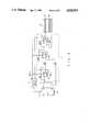
- FIG. 2is a block diagram of a control circuit for the liquid crystal rear vision-mirror according to the present invention
- FIG. 3is an electrical schematic diagram of a preferred embodiment of FIG. 2 according to the invention.
- FIG. 4is an electrical schematic diagram of another embodiment of a voltage driver
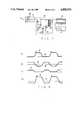
- FIG. 5are waveforms showing aspects of operation of the invention.
- FIG. 6is a block diagram of other embodiment of a control circuit for the liquid crystal rear-vision mirror according to the invention.
- FIG. 7is an electrical schematic diagram of the block diagram in FIG. 6.
- FIG. 8are waveforms showing aspects of operation in FIG. 7.
- FIGS. 1(A), (B), (C)show the structure of the liquid crystal rear-vision mirror and the response characteristic curve to the voltage applied thereto, respectively.
- the configuration of the liquid crystal rear vision mirrorcomprises upper and lower transparent electrodes 12A,12B formed by evaporation on each inner surface of upper and lower glass substrate 11A,11B to apply electric field upper and lower orientation control film 14A,14B for uniformly maintaining the orientation of the liquid crystal formed on each inner side of each upper and lower transparent electrodes 12A,12B seal material 13A,13B for injecting and sealing liquid crystal material 16 between the upper and lower orientation control film 14A,14B and a reflecting film 15 for reflecting the light formed by evaporation on the lower portion of the glass substrate 11B.
- GH-typed liquid crystalis used in which the guest pigment is added to a mixture of Nematic liquid crystal and Colesteric liquid crystal.
- a GH-typed compoundis treated to be oriented vertically so that it is arranged parallel to upper and lower grass substrate 11A,11B to prevent the incident light from passing there through when the voltage is applied thereto.
- liquid crystal compoundis arranged vertically to the direction of the electric field during application of the electrical field, the incident light is absorbed to reduce the amount of the reflecting light.
- the incident lightis reflected by the reflecting plate 15, whereby the liquid crystal compound acts as a mirror.
- the response characteristics of such liquid crystal 16shows that the initial rising time(Zr) is proportional to the gap of the viscosity Ni of the liquid crystal material 16 and the square of the liquid crystal cell d 2 , and in inverse proportion to the square of the applied voltage; and the falling time(Zf) is proportional to the viscosity Ni of the liquid crystal material and the square of the gap of the liquid crystal cell d 2 .
- the viscosity of the liquid crystal materialshould be lowered, or the cell gap of liquid crystal 16 should be made short as well as the applied voltage should be increased, but the lowering of the viscosity in the liquid crystal material is limited due to the property of the liquid crystal and the procedure for shortening the cell gap has various problems during manufacturing. Therefore it is conventional to reduce the rising time as shown in FIG. 1(C) by increasing the driving voltage of liquid crystal 16 as shown in FIG. 1(B).
- FIG. 2shows the block diagram in accordance with the present invention
- the control circuit of the liquid crystal rear-vision mirrorcomprises light sensing and comparing means 1 for sensing the strength and weakness of the incident light, and converting it into the sensing voltage, and comparing the converted voltage with the predetermined reference level voltage, and outputting the comparing value of the amount of the incident light; oscillator 2 for receiving the comparing value of the amount of the incident light from said light sensing and comparing means 1 and oscillating/outputting a square wave having a constant period; pulse generating means 3 for receiving the square wave oscillating signal from said oscillator 2 and outputting the operating voltages at a predetermined level, the phases of which are different from each other; and voltage driver 4 for converting into the predetermined voltage level the liquid crystal operating voltages of said pulse generating means 3, the phases of which are different from each other and applying the operating voltages to liquid crystal rear-vision mirror 5.
- the control circuitsenses the amount of the incident light, converts it into the electric signal and the electric signal with the predetermined reference signal and outputs the comparing value of the amount of the incident light to the oscillator 2 when the incident light is larger than the predetermined reference signal.
- the oscillator 2 receiving the comparing value of the amount of the incident light from the light sensing and comparing means 1begins to generate a square wave having the constant period and to output it to the pulse generating means 3.
- the pulse generating means 3receiving the square wave having the constant period from the oscillator 2, generates a predetermined level of the square wave having phases of which are inverted from each other, and outputs the operating voltage to the voltage driver 4.
- the voltage driver 4buffers the operating voltage to a predetermined level and outputs to the upper and lower transparent electrode of liquid crystal rear-vision mirror 5.
- liquid crystal rear-vision mirror 5is operated by the square wave voltage buffered and generated at the voltage driver 4 and scatteringly reflects the incident light.
- FIG. 3shows the detailed circuit of one embodiment of the block diagram of FIG. 2.
- This circuitcomprises the light sensing and comparing means 1, in which source voltage(VDD) of the auto is applied to the voltage divide circuit including resistor R1 and R2 connected in series and the cathode of photo diode PD having the anode connected to load resistor R3 for bypassing the dark current; the divided voltage by resistor R1 and R2 is connected to the inverting terminal(-) of comparator OP1 and the light sensing signal is inputting to the non-inverting terminal(+) of comparator OP1; such comparator OP1 compares the divided voltage with the light sensing signal, Also its output terminal has the capacitor C1 connected in series to resistor R4 one end of which is coupled to source voltage VDD.
- Capacitor C1compensates for the output of comparator OP1; and the oscillator 2, in which resistor R5 is connected in parallel to resistor R4 and controls the current of the source.
- Zener diodes ZD1, ZD2are coupled in series with resistor R5 in order to clamp the source voltage at the predetermined level resistors R6, R7 are connected in parallel to resistor R5 to divide the source voltage clamped/outputted by the zener diodes and by the resistor; resistor R8 drops the output voltage of resistor R5 and outputs it as the predetermined voltage, the output of resistor R8 and comparator OP1 is applied to comparator OP2 as the operating voltage, the divided voltage by resistor R6, R7 is applied through resistor R9 to the non-inverting terminal of comparator OP2, thereby outputting the predetermined signal by comparator OP2, and capacitor C2 is connected in series to resistor R10 for feeding back the output of comparator OP2, thereby discharging the voltage charged through resistor R10
- Reference number 6is the circuit for practicing the other process of the present invention, it is a voltage booster circuit for increasing the source voltage to the maximum applicable allowance voltage of C-MOS buffer 4A, 4B connected to resistor R5 and its output is connected to source voltage terminal VDD of C-MOS 4A, 4B.
- FIG. 4shows another embodiment of the voltage driver circuit portion of FIG. 3.
- Output terminal Q of latch circuit 3Ais connected to the inverting terminal(-) of inverting amplifier OP3 to which feedback resister R12 is coupled while, the non-inverting terminal(+) of inverting amplifier OP3 is coupled to a reference ground.
- the output amplified by inverting amplifier OP3is supplied to the non-inverting terminal(+) of adding amplifier OP4 through resistor R13.
- Also output of latch circuit 3Ais coupled through resistor R14 to the non-inverting terminal of adding amplifier OP4.
- Adding amplifier OP4has the inverting terminal(-) coupled to feedback resistor R15 and the output terminal connected to lower transparent electrode 12B of liquid crystal rear-vision mirror 5 and the inverting terminal(-) of inverting amplifier OP5.
- Inverting amplifier(OP5)has the inverting terminal(-) connected to feedback resistor R16 and the output coupled to upper transparent electrode 12A of liquid crystal rear-vision mirror to operate liquid crystal rear-vision mirror 5.
- Both of the source terminal (Vcc,-Vcc) of amplifier OP3, OP4 and OP5receive the positive and negative voltage output of a step-up voltage circuit, namely booster circuit 6.
- FIG. 5shows the operating waveforms of each portion of FIG. 3 and FIG. 4.
- the waveform Ais a waveform to be outputted from comparator OP2 of the oscillator.
- the waveform Bis a wave form of inverter IN1.
- the waveform C,Dare waveform of the liquid crystal operating voltage from latch circuit 3A.
- the waveform Eis the operating waveform that is operated by C-MOS buffer 4A, 4B and inputted into liquid crystal rear-vision mirror 5 to operate the liquid crystal.
- the waveform F, G, Hare outputting waveform of amplifier OP3, OP4, OP5 of FIG. 4.
- the waveform Iis the waveform that is inputted into liquid crystal rear-vision mirror 5.
- comparator OP1normally outputs the low level signal. But when photodiode PD receives the head light of the auto at the back, photodiode PD is turned on and converts the light into the electric signal. Thus source voltage VDD is divided by the "on" resistance of photodiode PD and resistor R3, and light amount sensing voltage Vp is applied to the non-inverting terminal(+) of comparator OP1.
- the light amount sensing voltage(Vp) divided by the "on" resistance of photodiode PD and resistor R3is higher than the reference voltage divided by resistor R1, R2 so that comparator OP1 may output the high level signal of the source voltage VDD between resistor R4 and capacitor C1. Then the high level signal outputted from comparator OP1 is inputted to comparator OP2 along with the voltage applied through resistor R8 to the source terminal Vcc2 of compurator OP2 to operate comparator OP2.
- comparator OP2receives the voltage that is clamped by zener diode ZD1, ZD2 and divided by resistor R6, R7. Comparator OP2 compares it with the signal to its inverting terminal(-) and outputs the high level signal as initially shown in FIG. 5(A). Then the signal from comparator OP2 is fed back by resistor R11 and charges capacitor C2. When the charging voltage of capacitor C2 is higher than the voltage inputted to the non-inventing terminal of comparator OP2, comparator OP2 is made low at its output as shown in FIG. 5(A), thereby causing continuous oscillation.
- comparator OP2determines the oscillation period of comparator OP2 and controlled by the time constant value RC of resistor R11 and capacitor C2. Then as comparator OP2 continues to output the waveform signal of FIG. 5(A), inverter IN1 inverts the signal of FIG. 5(A) and applies the signal of FIG. 5(B) to clock terminal CK of latch circuit 3A.
- Latch circuit 3Aoutputs from its output terminals Q, Q to C-MOS buffer 4A, 4B the square wave signals at the 12 volt level of the source voltage(VDD) respectively, the phases of which are different from each other. For example, the output terminal Q of latch circuit 3A outputs the high level signal at the rising edge of the waveform shown in FIG. 5(B) as shown in FIG.
- C-MOS buffers 4A, 4Breceiving the wavefrom signals of FIG. 5(C) and FIG. 5(D) from latch circuit 3A buffers signals having the voltage level of the source voltage VDD and outputs the signals to upper and lower transparent electrodes 12A,12B of liquid crystal rear-vision mirror 5, whereby liquid crystal rear-vision mirror 5 is operated by the voltage having the square wave of FIG. 5(E) and scatters the incident light.
- C-MOS buffers 4A, 4Bare used to compensate for the dropping down of the operating voltage caused by the area of the liquid crystal rear-vision mirror when the operating voltage is applied the transparent electrode 12A,12B.
- the voltage boosting circuit 6is used as the other embodiment of the present invention, it is connected to the source line to boost the source voltage to the maximum usable voltage (for example about 18 V) and to apply the boosted voltage to operating voltage terminal VDD of C-MOS buffer 4A, 4B.
- C-MOS buffers 4A, 4Bbuffer the square wave voltages having different phases as shown in FIGS.
- the maximum allowable voltage of the operational amplifier or the C-MOS integrated circuitis normally about 18 volts.
- FIG. 4is another embodiment of the voltage driver when voltage boosting circuit 6 in FIG. 3 is used. Its confiquration is described as above.
- latch circuit 3Aoutputs the square wave signals of FIGS. 5(C),(D) from its output terminal Q, Q so that the output of FIG. 5(D) is applied to the inverting terminal(-) of inverting amplifier OP3 and the output of FIG. (C) is inputted through resistor R14 to the non-inverting terminal of adding amplifier OP4.
- Inverting amplifier OP3 receiving the operating signal from output terminal Q of latch circuit 3Aapplies the signal of FIG.
- non-inverting add amplifier OP4receives at its non-inverting terminal(+) the signal from the output terminal Q of latch circuit 3A through resistor R14.
- the non-inverting add amplifier OP4adds and amplifies the signal through feed-back resistor R15 and outputs the signal of FIG. 5(G) to lower transparent electrode 12B of liquid crystal rear-vision mirror 5 as well as to the inverting terminal(-) of inverting amplifier OP5.
- Inverting amplifier OP5receiving the signal of FIG.
- the peak to peak voltage(Vpp)gets the C-MOS allowable operating voltage from voltage boosting circuit 6 to input to the voltage inputting terminal(Vcc), (-Vcc) of each of allowable operating OP3, OP4, OP4 to the upper limit value and the lower limit value of C-MOS operating allowance voltage. Therefore it is known that liquid crystal rear-vision mirror 5 is operated in high speed as described above in FIG. 1 by receiving the peak to peak voltage signal.
- FIG. 6shows the block diagram of the other embodiment in accordance with the present invertion.
- This embodimentcomprises light sensing and comparing means 10 for sensing the incident light and outputting the light sensing comparision signal, DC-AC inverter 20 for receiving the light sensing comparision signal from light sensing and comparing means 10 and inverting the DC voltage into an AC signal having the constant period by the operation of the constant oscillating period as well as outputting the AC signal, DC power supply 30 for supplying the constant DC voltage and liquid crystal rear-vision mirror 40 for receiving the signal from DC-AC inverter 20 and the DC voltage signal from DC power supply 30.
- FIG. 7shows the detailed circuit of the embodiment of FIG. 6.
- the light sensing and comparing means 10has the configuration equal to that of light sensing and comparing means 1 shown in FIG. 1. Also this embodiment comprises DC-AC inverting circuit 20, in which the DC voltage output from light sensing and comparing means 10 is applied to primary side 21 of transformer T as well as to resistor R17 and collector of switching transistor Q1 connected in parallel to each other for controlling the current induced at the secondary side. Then the voltage dropped by resistor R17 is applied to capacitor C10 for compensating for the response characteristic and the base of transistor Q1, and further is connected through resistor R18 and capacitor C12 to the secondary side 24 having the middle tap 26.
- DC power supply 30 for supplying the constant DC voltageis connected to liquid crystal rear-vision mirror 40 operated by the AC voltage from the output 25 of transformer T and the DC voltage of DC power supply 30.
- FIG. 8shows aspects of operation of each portion of FIG. 7.
- the waveform(A)is a waveform in the primary side of transformer caused by the "turn-off" of transistors Q1,Q2.
- the waveform Bis a voltage waveform induced at the secondary side 24 of transformer T by the "turn on” and the “turn off” of transistors Q1, Q2.
- the waveform Cis a waveform of reverse electromotive force in a point 23 by the switching operation of transistors Q1, Q2.
- the waveform Dis the sinusoidal waveform output boosted by secondary side of transformer T.
- the light sensing and comparing means 10senses the amount of the incident light as described above with reference to FIG. 3.
- the source voltage(VDD)is applied to resistor R17 and the collector of transistor Q1 as well as to first side 21 of transformer T, so that the current passing through resistor R17 is inputted to the base of transistor Q1 to turn on transistor Q1 while charging capacitor C12 through resistor R18 by the time constant of RC. Therefore the "turn on" current of transistor Q1 forms a current 100 p including the primary side 21 of transformer T and transistor Q2 to which the DC voltage from the light sensing and comparing means 10 is applied. Accordingly as the capacitor C12 is charged and then discharged, the reverse electromotive force as shown in FIG.
- first side 22is negative like the waveform(85) shown in FIG. 8(A), so that thus the positive voltage like the waveform(86) shown in FIG. 8(B) is induced at point 24 of the secondary side and the negative voltage like the waveform(87) shown in FIG. 8(D) is generated and outputted at point 25 of the secondary side, wherein capacitor C11 acts to eliminate the noise caused by the "turn off” of transistor Q2 and capacitor C10 acts to improve the "turn on and off” characteristics of transistors Q1, Q2.
- light sensing and comparing means 10senses the amount of the incident light and outputs the predetermined DC voltage to resistor R17, transistor Q1 and primary side 21 of transformer T, the boosted signal like the waveform of FIG.
- this inventionhas the advantage for allowing the driver to safely drive by reducing the reflecting light directed to him.
- this inventionautomatically outputs the operating voltage for liquid crystal rear-vision mirror to increased the response speed of the liquid crystal, thereby automatically operating the liquid crystal rear-vision mirror whenever the headlight of the auto at the back becomes strong.
Landscapes
- Engineering & Computer Science (AREA)
- Multimedia (AREA)
- Mechanical Engineering (AREA)
- Chemical & Material Sciences (AREA)
- Crystallography & Structural Chemistry (AREA)
- Liquid Crystal Display Device Control (AREA)
- Liquid Crystal (AREA)
Abstract
Description
ZrαNi.d.sup.2 /V.sup.2 (1)
ZrαNi·d.sup.2 (2)
Claims (11)
Applications Claiming Priority (2)
| Application Number | Priority Date | Filing Date | Title |
|---|---|---|---|
| KR860011703AKR880007296A (en) | 1986-12-31 | 1986-12-31 | LCD rearview driving circuit |
| KR1986-11703 | 1986-12-31 |
Publications (1)
| Publication Number | Publication Date |
|---|---|
| US4820933Atrue US4820933A (en) | 1989-04-11 |
Family
ID=19254690
Family Applications (1)
| Application Number | Title | Priority Date | Filing Date |
|---|---|---|---|
| US07/139,736Expired - LifetimeUS4820933A (en) | 1986-12-31 | 1987-12-30 | Control circuit for liquid crystal rear-vision mirror |
Country Status (3)
| Country | Link |
|---|---|
| US (1) | US4820933A (en) |
| JP (1) | JPS63179330A (en) |
| KR (1) | KR880007296A (en) |
Cited By (79)
| Publication number | Priority date | Publication date | Assignee | Title |
|---|---|---|---|---|
| US5064274A (en)* | 1987-08-26 | 1991-11-12 | Siegel-Robert, Inc. | Automatic automobile rear view mirror assembly |
| FR2673005A1 (en)* | 1991-02-18 | 1992-08-21 | Asulab Sa | Frequency-controlled optical device |
| EP0499878A1 (en)* | 1991-02-13 | 1992-08-26 | Asulab S.A. | Frequency controlled optical device |
| US5193029A (en)* | 1991-11-19 | 1993-03-09 | Donnelly Corporation | Single sensor adaptive drive circuit for rearview mirror system |
| US5223814A (en)* | 1988-12-05 | 1993-06-29 | Prince Corporation | Sensor for vehicle accessories |
| US5267067A (en)* | 1991-02-13 | 1993-11-30 | Asulab S.A. | Frequency controllable optical device |
| US5550677A (en)* | 1993-02-26 | 1996-08-27 | Donnelly Corporation | Automatic rearview mirror system using a photosensor array |
| US5564813A (en)* | 1994-03-30 | 1996-10-15 | United Technologies Automotive, Inc. | Sun visor lamp |
| US5583485A (en)* | 1988-12-05 | 1996-12-10 | Prince Corporation | Trainable transmitter and receiver |
| US5614885A (en)* | 1988-12-05 | 1997-03-25 | Prince Corporation | Electrical control system for vehicle options |
| US5768020A (en)* | 1994-11-09 | 1998-06-16 | Murakami Kaimeido Co., Ltd. | Automatic anti-glare rearview mirror system |
| US6302545B1 (en) | 1993-02-26 | 2001-10-16 | Donnelly Corporation | Vehicle control system and method |
| US20070023613A1 (en)* | 1993-02-26 | 2007-02-01 | Donnelly Corporation | Vehicle headlight control using imaging sensor |
| US20070109406A1 (en)* | 1993-02-26 | 2007-05-17 | Donnelly Corporation, A Corporation Of The State Of Michigan | Image sensing system for a vehicle |
| US20070252640A1 (en)* | 2006-04-28 | 2007-11-01 | Yen-Tai Lin | Voltage regulator outputting positive and negative voltages with the same offsets |
| US20090015736A1 (en)* | 2005-11-01 | 2009-01-15 | Donnelly Corporation | Interior rearview mirror assembly with display |
| US20090045323A1 (en)* | 2007-08-17 | 2009-02-19 | Yuesheng Lu | Automatic Headlamp Control System |
| US7526103B2 (en) | 2004-04-15 | 2009-04-28 | Donnelly Corporation | Imaging system for vehicle |
| US20090219394A1 (en)* | 1998-01-07 | 2009-09-03 | Donnelly Corporation | Accessory mounting system suitable for use in a vehicle |
| US20090243634A1 (en)* | 2008-03-25 | 2009-10-01 | Lear Corporation | Capacitive sensing in an automotive mirror |
| US20100020170A1 (en)* | 2008-07-24 | 2010-01-28 | Higgins-Luthman Michael J | Vehicle Imaging System |
| US7655894B2 (en) | 1996-03-25 | 2010-02-02 | Donnelly Corporation | Vehicular image sensing system |
| US20100114509A1 (en)* | 2007-02-08 | 2010-05-06 | Techimp Technologies S.A. | Method for processing data pertaining to an activity of partial electrical discharges |
| US20100214791A1 (en)* | 2006-08-11 | 2010-08-26 | Donnelly Corporation | Automatic headlamp control system |
| US7821697B2 (en) | 1994-05-05 | 2010-10-26 | Donnelly Corporation | Exterior reflective mirror element for a vehicular rearview mirror assembly |
| US7859737B2 (en) | 2002-09-20 | 2010-12-28 | Donnelly Corporation | Interior rearview mirror system for a vehicle |
| US7864399B2 (en) | 2002-09-20 | 2011-01-04 | Donnelly Corporation | Reflective mirror assembly |
| US7871169B2 (en) | 1994-05-05 | 2011-01-18 | Donnelly Corporation | Vehicular signal mirror |
| US20110035120A1 (en)* | 2000-03-02 | 2011-02-10 | Donnelly Corporation | Vehicular wireless communication system |
| US7898719B2 (en) | 2003-10-02 | 2011-03-01 | Donnelly Corporation | Rearview mirror assembly for vehicle |
| US7898398B2 (en) | 1997-08-25 | 2011-03-01 | Donnelly Corporation | Interior mirror system |
| US7906756B2 (en) | 2002-05-03 | 2011-03-15 | Donnelly Corporation | Vehicle rearview mirror system |
| US7916009B2 (en) | 1998-01-07 | 2011-03-29 | Donnelly Corporation | Accessory mounting system suitable for use in a vehicle |
| US7914188B2 (en) | 1997-08-25 | 2011-03-29 | Donnelly Corporation | Interior rearview mirror system for a vehicle |
| US7918570B2 (en) | 2002-06-06 | 2011-04-05 | Donnelly Corporation | Vehicular interior rearview information mirror system |
| US7926960B2 (en) | 1999-11-24 | 2011-04-19 | Donnelly Corporation | Interior rearview mirror system for vehicle |
| US8019505B2 (en) | 2003-10-14 | 2011-09-13 | Donnelly Corporation | Vehicle information display |
| US8044776B2 (en) | 2000-03-02 | 2011-10-25 | Donnelly Corporation | Rear vision system for vehicle |
| US8049640B2 (en) | 2003-05-19 | 2011-11-01 | Donnelly Corporation | Mirror assembly for vehicle |
| US8063759B2 (en) | 1993-02-26 | 2011-11-22 | Donnelly Corporation | Vehicle vision system |
| US8070332B2 (en) | 2007-07-12 | 2011-12-06 | Magna Electronics Inc. | Automatic lighting system with adaptive function |
| US8072318B2 (en) | 2001-01-23 | 2011-12-06 | Donnelly Corporation | Video mirror system for vehicle |
| US8083386B2 (en) | 2001-01-23 | 2011-12-27 | Donnelly Corporation | Interior rearview mirror assembly with display device |
| US8154418B2 (en) | 2008-03-31 | 2012-04-10 | Magna Mirrors Of America, Inc. | Interior rearview mirror system |
| US8189871B2 (en) | 2004-09-30 | 2012-05-29 | Donnelly Corporation | Vision system for vehicle |
| US8194133B2 (en) | 2000-03-02 | 2012-06-05 | Donnelly Corporation | Vehicular video mirror system |
| US8217830B2 (en) | 2007-01-25 | 2012-07-10 | Magna Electronics Inc. | Forward facing sensing system for a vehicle |
| US8277059B2 (en) | 2002-09-20 | 2012-10-02 | Donnelly Corporation | Vehicular electrochromic interior rearview mirror assembly |
| US8282226B2 (en) | 2002-06-06 | 2012-10-09 | Donnelly Corporation | Interior rearview mirror system |
| US8288711B2 (en) | 1998-01-07 | 2012-10-16 | Donnelly Corporation | Interior rearview mirror system with forwardly-viewing camera and a control |
| US8294975B2 (en) | 1997-08-25 | 2012-10-23 | Donnelly Corporation | Automotive rearview mirror assembly |
| US8446470B2 (en) | 2007-10-04 | 2013-05-21 | Magna Electronics, Inc. | Combined RGB and IR imaging sensor |
| US8451107B2 (en) | 2007-09-11 | 2013-05-28 | Magna Electronics, Inc. | Imaging system for vehicle |
| US8462204B2 (en) | 1995-05-22 | 2013-06-11 | Donnelly Corporation | Vehicular vision system |
| US8503062B2 (en) | 2005-05-16 | 2013-08-06 | Donnelly Corporation | Rearview mirror element assembly for vehicle |
| US8525703B2 (en) | 1998-04-08 | 2013-09-03 | Donnelly Corporation | Interior rearview mirror system |
| US8665079B2 (en) | 2002-05-03 | 2014-03-04 | Magna Electronics Inc. | Vision system for vehicle |
| US8874317B2 (en) | 2009-07-27 | 2014-10-28 | Magna Electronics Inc. | Parking assist system |
| US8890955B2 (en) | 2010-02-10 | 2014-11-18 | Magna Mirrors Of America, Inc. | Adaptable wireless vehicle vision system based on wireless communication error |
| US9014904B2 (en) | 2004-12-23 | 2015-04-21 | Magna Electronics Inc. | Driver assistance system for vehicle |
| US9019091B2 (en) | 1999-11-24 | 2015-04-28 | Donnelly Corporation | Interior rearview mirror system |
| US9041806B2 (en) | 2009-09-01 | 2015-05-26 | Magna Electronics Inc. | Imaging and display system for vehicle |
| US9085261B2 (en) | 2011-01-26 | 2015-07-21 | Magna Electronics Inc. | Rear vision system with trailer angle detection |
| US9117123B2 (en) | 2010-07-05 | 2015-08-25 | Magna Electronics Inc. | Vehicular rear view camera display system with lifecheck function |
| US9126525B2 (en) | 2009-02-27 | 2015-09-08 | Magna Electronics Inc. | Alert system for vehicle |
| US9191574B2 (en) | 2001-07-31 | 2015-11-17 | Magna Electronics Inc. | Vehicular vision system |
| US9245448B2 (en) | 2001-07-31 | 2016-01-26 | Magna Electronics Inc. | Driver assistance system for a vehicle |
| US9264672B2 (en) | 2010-12-22 | 2016-02-16 | Magna Mirrors Of America, Inc. | Vision display system for vehicle |
| US9397492B2 (en)* | 2010-07-30 | 2016-07-19 | Hottinger Baldwin Messtechnik Gmbh | Protective circuit |
| US9446713B2 (en) | 2012-09-26 | 2016-09-20 | Magna Electronics Inc. | Trailer angle detection system |
| US9495876B2 (en) | 2009-07-27 | 2016-11-15 | Magna Electronics Inc. | Vehicular camera with on-board microcontroller |
| US9558409B2 (en) | 2012-09-26 | 2017-01-31 | Magna Electronics Inc. | Vehicle vision system with trailer angle detection |
| US9576694B2 (en) | 2010-09-17 | 2017-02-21 | Drexel University | Applications for alliform carbon |
| US9752932B2 (en) | 2010-03-10 | 2017-09-05 | Drexel University | Tunable electro-optic filter stack |
| US9900522B2 (en) | 2010-12-01 | 2018-02-20 | Magna Electronics Inc. | System and method of establishing a multi-camera image using pixel remapping |
| US10132971B2 (en) | 2016-03-04 | 2018-11-20 | Magna Electronics Inc. | Vehicle camera with multiple spectral filters |
| US10160382B2 (en) | 2014-02-04 | 2018-12-25 | Magna Electronics Inc. | Trailer backup assist system |
| US10793067B2 (en) | 2011-07-26 | 2020-10-06 | Magna Electronics Inc. | Imaging system for vehicle |
| US10875403B2 (en) | 2015-10-27 | 2020-12-29 | Magna Electronics Inc. | Vehicle vision system with enhanced night vision |
Families Citing this family (1)
| Publication number | Priority date | Publication date | Assignee | Title |
|---|---|---|---|---|
| FR2933504B1 (en)* | 2008-07-04 | 2011-11-04 | Saint Gobain | METHOD FOR ELECTRICALLY SECURING AN ELECTRICAL POWER SUPPLY OF AN ELECTROCOMMANDABLE SYSTEM WITH VARIABLE OR LIGHTING OPTICAL PROPERTIES, USES OF THE ELECTRICALLY SECURED SYSTEM |
Citations (10)
| Publication number | Priority date | Publication date | Assignee | Title |
|---|---|---|---|---|
| US4021935A (en)* | 1976-02-20 | 1977-05-10 | Frank Witt | Flight training hood |
| US4560239A (en)* | 1984-02-29 | 1985-12-24 | Amnon Katz | Liquid crystal active light shield |
| US4603946A (en)* | 1982-09-29 | 1986-08-05 | Kabushiki Kaisha Tokai Rika Denki Seisakusho | Reflection controllable view mirror device for motor vehicle or the like |
| US4620322A (en)* | 1982-04-14 | 1986-11-04 | Andre M. Eggenschwiler | Electro-optic welding lens assembly |
| US4632509A (en)* | 1983-11-29 | 1986-12-30 | Nippondenso Co., Ltd. | Glare-shielding type reflector |
| US4669825A (en)* | 1983-12-27 | 1987-06-02 | Nippondenso Co., Ltd. | Control apparatus with delay circuit for antiglare mirror |
| US4678281A (en)* | 1984-03-26 | 1987-07-07 | Rainer Bauer | Circuit for the actuation of liquid crystal layers in mirrors |
| US4690508A (en)* | 1982-12-15 | 1987-09-01 | C-D Marketing, Ltd. | Liquid crystal closed-loop controlled mirror systems |
| US4697883A (en)* | 1984-08-30 | 1987-10-06 | Nippondenso Co., Ltd. | Control apparatus for two section, glare shield mirror |
| US4701022A (en)* | 1984-11-28 | 1987-10-20 | C-D Marketing, Ltd. | Day/night mirror |
Family Cites Families (3)
| Publication number | Priority date | Publication date | Assignee | Title |
|---|---|---|---|---|
| JPS49128429A (en)* | 1973-04-16 | 1974-12-09 | ||
| JPS55149902A (en)* | 1979-05-12 | 1980-11-21 | Aoki Eng Kk | Electronically controlled rear-vision mirror |
| DE3127720A1 (en)* | 1981-07-14 | 1983-02-10 | Hohe Kg, 6981 Collenberg | DIMMABLE REAR-VIEW MIRROR, IN PARTICULAR FOR MOTOR VEHICLES |
- 1986
- 1986-12-31KRKR860011703Apatent/KR880007296A/ennot_activeWithdrawn
- 1987
- 1987-12-23JPJP62324227Apatent/JPS63179330A/enactivePending
- 1987-12-30USUS07/139,736patent/US4820933A/ennot_activeExpired - Lifetime
Patent Citations (11)
| Publication number | Priority date | Publication date | Assignee | Title |
|---|---|---|---|---|
| US4021935A (en)* | 1976-02-20 | 1977-05-10 | Frank Witt | Flight training hood |
| US4152846A (en)* | 1976-02-20 | 1979-05-08 | Witt Frank A | Flight training method and apparatus |
| US4620322A (en)* | 1982-04-14 | 1986-11-04 | Andre M. Eggenschwiler | Electro-optic welding lens assembly |
| US4603946A (en)* | 1982-09-29 | 1986-08-05 | Kabushiki Kaisha Tokai Rika Denki Seisakusho | Reflection controllable view mirror device for motor vehicle or the like |
| US4690508A (en)* | 1982-12-15 | 1987-09-01 | C-D Marketing, Ltd. | Liquid crystal closed-loop controlled mirror systems |
| US4632509A (en)* | 1983-11-29 | 1986-12-30 | Nippondenso Co., Ltd. | Glare-shielding type reflector |
| US4669825A (en)* | 1983-12-27 | 1987-06-02 | Nippondenso Co., Ltd. | Control apparatus with delay circuit for antiglare mirror |
| US4560239A (en)* | 1984-02-29 | 1985-12-24 | Amnon Katz | Liquid crystal active light shield |
| US4678281A (en)* | 1984-03-26 | 1987-07-07 | Rainer Bauer | Circuit for the actuation of liquid crystal layers in mirrors |
| US4697883A (en)* | 1984-08-30 | 1987-10-06 | Nippondenso Co., Ltd. | Control apparatus for two section, glare shield mirror |
| US4701022A (en)* | 1984-11-28 | 1987-10-20 | C-D Marketing, Ltd. | Day/night mirror |
Cited By (360)
| Publication number | Priority date | Publication date | Assignee | Title |
|---|---|---|---|---|
| US5064274A (en)* | 1987-08-26 | 1991-11-12 | Siegel-Robert, Inc. | Automatic automobile rear view mirror assembly |
| US5691848A (en)* | 1988-12-05 | 1997-11-25 | Prince Corporation | Electrical control system for vehicle options |
| US5223814A (en)* | 1988-12-05 | 1993-06-29 | Prince Corporation | Sensor for vehicle accessories |
| US5699044A (en)* | 1988-12-05 | 1997-12-16 | Prince Corporation | Electrical control system for vehicle options |
| US5583485A (en)* | 1988-12-05 | 1996-12-10 | Prince Corporation | Trainable transmitter and receiver |
| US5614885A (en)* | 1988-12-05 | 1997-03-25 | Prince Corporation | Electrical control system for vehicle options |
| US5661455A (en)* | 1988-12-05 | 1997-08-26 | Prince Corporation | Electrical control system for vehicle options |
| EP0499878A1 (en)* | 1991-02-13 | 1992-08-26 | Asulab S.A. | Frequency controlled optical device |
| US5267067A (en)* | 1991-02-13 | 1993-11-30 | Asulab S.A. | Frequency controllable optical device |
| FR2673005A1 (en)* | 1991-02-18 | 1992-08-21 | Asulab Sa | Frequency-controlled optical device |
| US5193029A (en)* | 1991-11-19 | 1993-03-09 | Donnelly Corporation | Single sensor adaptive drive circuit for rearview mirror system |
| US20070109651A1 (en)* | 1993-02-26 | 2007-05-17 | Donnelly Corporation | Image sensing system for a vehicle |
| US7325934B2 (en) | 1993-02-26 | 2008-02-05 | Donnelly Corporation | Image sensing system for a vehicle |
| US5760962A (en)* | 1993-02-26 | 1998-06-02 | Donnelly Corporation | Automatic rearview mirror system using a photosensor array |
| US7859565B2 (en) | 1993-02-26 | 2010-12-28 | Donnelly Corporation | Vision system for a vehicle including image processor |
| US6302545B1 (en) | 1993-02-26 | 2001-10-16 | Donnelly Corporation | Vehicle control system and method |
| US6523964B2 (en) | 1993-02-26 | 2003-02-25 | Donnelly Corporation | Vehicle control system and method |
| US6802617B2 (en) | 1993-02-26 | 2004-10-12 | Donnelly Corporation | Vehicle image capture system |
| US20050146792A1 (en)* | 1993-02-26 | 2005-07-07 | Donnelly Corporation, A Corporation Of The State Of Michigan | Monitoring system |
| US6953253B2 (en) | 1993-02-26 | 2005-10-11 | Donnelly Corporation | Vehicle photosensing control system |
| US20060028731A1 (en)* | 1993-02-26 | 2006-02-09 | Kenneth Schofield | Vehicular vision system |
| US20070023613A1 (en)* | 1993-02-26 | 2007-02-01 | Donnelly Corporation | Vehicle headlight control using imaging sensor |
| US20070109653A1 (en)* | 1993-02-26 | 2007-05-17 | Kenneth Schofield | Image sensing system for a vehicle |
| US20070109406A1 (en)* | 1993-02-26 | 2007-05-17 | Donnelly Corporation, A Corporation Of The State Of Michigan | Image sensing system for a vehicle |
| US8314689B2 (en) | 1993-02-26 | 2012-11-20 | Donnelly Corporation | Vehicular vision system |
| US20070109654A1 (en)* | 1993-02-26 | 2007-05-17 | Donnelly Corporation, A Corporation Of The State Of Michigan | Image sensing system for a vehicle |
| US20070176080A1 (en)* | 1993-02-26 | 2007-08-02 | Donnelly Corporation | Image sensing system for a vehicle |
| US8063759B2 (en) | 1993-02-26 | 2011-11-22 | Donnelly Corporation | Vehicle vision system |
| US7311406B2 (en) | 1993-02-26 | 2007-12-25 | Donnelly Corporation | Image sensing system for a vehicle |
| US7325935B2 (en) | 1993-02-26 | 2008-02-05 | Donnelly Corporation | Image sensing system for a vehicle |
| US8203440B2 (en) | 1993-02-26 | 2012-06-19 | Donnelly Corporation | Vehicular vision system |
| US7339149B1 (en) | 1993-02-26 | 2008-03-04 | Donnelly Corporation | Vehicle headlight control using imaging sensor |
| US20080054161A1 (en)* | 1993-02-26 | 2008-03-06 | Donnelly Corporation | Image sensing system for a vehicle |
| US7344261B2 (en) | 1993-02-26 | 2008-03-18 | Donnelly Corporation | Vehicular vision system |
| US7380948B2 (en) | 1993-02-26 | 2008-06-03 | Donnelly Corporation | Image sensing system for a vehicle |
| US7388182B2 (en) | 1993-02-26 | 2008-06-17 | Donnelly Corporation | Image sensing system for controlling an accessory or headlight of a vehicle |
| US7402786B2 (en) | 1993-02-26 | 2008-07-22 | Donnelly Corporation | Vehicle headlight control using imaging sensor with spectral filtering |
| US7423248B2 (en) | 1993-02-26 | 2008-09-09 | Donnelly Corporation | Automatic exterior light control for a vehicle |
| US8098142B2 (en) | 1993-02-26 | 2012-01-17 | Magna Mirrors Of America, Inc. | Vehicle monitoring system |
| US7425076B2 (en) | 1993-02-26 | 2008-09-16 | Donnelly Corporation | Vision system for a vehicle |
| US8599001B2 (en) | 1993-02-26 | 2013-12-03 | Magna Electronics Inc. | Vehicular vision system |
| US8917169B2 (en) | 1993-02-26 | 2014-12-23 | Magna Electronics Inc. | Vehicular vision system |
| US7459664B2 (en) | 1993-02-26 | 2008-12-02 | Donnelly Corporation | Image sensing system for a vehicle |
| US5550677A (en)* | 1993-02-26 | 1996-08-27 | Donnelly Corporation | Automatic rearview mirror system using a photosensor array |
| US5564813A (en)* | 1994-03-30 | 1996-10-15 | United Technologies Automotive, Inc. | Sun visor lamp |
| US8164817B2 (en) | 1994-05-05 | 2012-04-24 | Donnelly Corporation | Method of forming a mirrored bent cut glass shape for vehicular exterior rearview mirror assembly |
| US8511841B2 (en) | 1994-05-05 | 2013-08-20 | Donnelly Corporation | Vehicular blind spot indicator mirror |
| US7871169B2 (en) | 1994-05-05 | 2011-01-18 | Donnelly Corporation | Vehicular signal mirror |
| US7821697B2 (en) | 1994-05-05 | 2010-10-26 | Donnelly Corporation | Exterior reflective mirror element for a vehicular rearview mirror assembly |
| US5768020A (en)* | 1994-11-09 | 1998-06-16 | Murakami Kaimeido Co., Ltd. | Automatic anti-glare rearview mirror system |
| US8559093B2 (en) | 1995-04-27 | 2013-10-15 | Donnelly Corporation | Electrochromic mirror reflective element for vehicular rearview mirror assembly |
| US8462204B2 (en) | 1995-05-22 | 2013-06-11 | Donnelly Corporation | Vehicular vision system |
| US7994462B2 (en) | 1996-03-25 | 2011-08-09 | Donnelly Corporation | Vehicular image sensing system |
| US8481910B2 (en) | 1996-03-25 | 2013-07-09 | Donnelly Corporation | Vehicular image sensing system |
| US8637801B2 (en) | 1996-03-25 | 2014-01-28 | Magna Electronics Inc. | Driver assistance system for a vehicle |
| US7655894B2 (en) | 1996-03-25 | 2010-02-02 | Donnelly Corporation | Vehicular image sensing system |
| US8993951B2 (en) | 1996-03-25 | 2015-03-31 | Magna Electronics Inc. | Driver assistance system for a vehicle |
| US8222588B2 (en) | 1996-03-25 | 2012-07-17 | Donnelly Corporation | Vehicular image sensing system |
| US8492698B2 (en) | 1996-03-25 | 2013-07-23 | Donnelly Corporation | Driver assistance system for a vehicle |
| US8324552B2 (en) | 1996-03-25 | 2012-12-04 | Donnelly Corporation | Vehicular image sensing system |
| US9131120B2 (en) | 1996-05-22 | 2015-09-08 | Magna Electronics Inc. | Multi-camera vision system for a vehicle |
| US8643724B2 (en) | 1996-05-22 | 2014-02-04 | Magna Electronics Inc. | Multi-camera vision system for a vehicle |
| US8842176B2 (en) | 1996-05-22 | 2014-09-23 | Donnelly Corporation | Automatic vehicle exterior light control |
| US8294975B2 (en) | 1997-08-25 | 2012-10-23 | Donnelly Corporation | Automotive rearview mirror assembly |
| US8610992B2 (en) | 1997-08-25 | 2013-12-17 | Donnelly Corporation | Variable transmission window |
| US8267559B2 (en) | 1997-08-25 | 2012-09-18 | Donnelly Corporation | Interior rearview mirror assembly for a vehicle |
| US8779910B2 (en) | 1997-08-25 | 2014-07-15 | Donnelly Corporation | Interior rearview mirror system |
| US8309907B2 (en) | 1997-08-25 | 2012-11-13 | Donnelly Corporation | Accessory system suitable for use in a vehicle and accommodating a rain sensor |
| US7898398B2 (en) | 1997-08-25 | 2011-03-01 | Donnelly Corporation | Interior mirror system |
| US8100568B2 (en) | 1997-08-25 | 2012-01-24 | Donnelly Corporation | Interior rearview mirror system for a vehicle |
| US8063753B2 (en) | 1997-08-25 | 2011-11-22 | Donnelly Corporation | Interior rearview mirror system |
| US7914188B2 (en) | 1997-08-25 | 2011-03-29 | Donnelly Corporation | Interior rearview mirror system for a vehicle |
| US7916009B2 (en) | 1998-01-07 | 2011-03-29 | Donnelly Corporation | Accessory mounting system suitable for use in a vehicle |
| US20090219394A1 (en)* | 1998-01-07 | 2009-09-03 | Donnelly Corporation | Accessory mounting system suitable for use in a vehicle |
| US8288711B2 (en) | 1998-01-07 | 2012-10-16 | Donnelly Corporation | Interior rearview mirror system with forwardly-viewing camera and a control |
| US7888629B2 (en) | 1998-01-07 | 2011-02-15 | Donnelly Corporation | Vehicular accessory mounting system with a forwardly-viewing camera |
| US8325028B2 (en) | 1998-01-07 | 2012-12-04 | Donnelly Corporation | Interior rearview mirror system |
| US7994471B2 (en) | 1998-01-07 | 2011-08-09 | Donnelly Corporation | Interior rearview mirror system with forwardly-viewing camera |
| US8134117B2 (en) | 1998-01-07 | 2012-03-13 | Donnelly Corporation | Vehicular having a camera, a rain sensor and a single-ball interior electrochromic mirror assembly attached at an attachment element |
| US8094002B2 (en) | 1998-01-07 | 2012-01-10 | Donnelly Corporation | Interior rearview mirror system |
| US8525703B2 (en) | 1998-04-08 | 2013-09-03 | Donnelly Corporation | Interior rearview mirror system |
| US9221399B2 (en) | 1998-04-08 | 2015-12-29 | Magna Mirrors Of America, Inc. | Automotive communication system |
| US9481306B2 (en) | 1998-04-08 | 2016-11-01 | Donnelly Corporation | Automotive communication system |
| US8884788B2 (en) | 1998-04-08 | 2014-11-11 | Donnelly Corporation | Automotive communication system |
| US9436880B2 (en) | 1999-08-12 | 2016-09-06 | Magna Electronics Inc. | Vehicle vision system |
| US8203443B2 (en) | 1999-08-12 | 2012-06-19 | Donnelly Corporation | Vehicle vision system |
| US8629768B2 (en) | 1999-08-12 | 2014-01-14 | Donnelly Corporation | Vehicle vision system |
| US7926960B2 (en) | 1999-11-24 | 2011-04-19 | Donnelly Corporation | Interior rearview mirror system for vehicle |
| US8162493B2 (en) | 1999-11-24 | 2012-04-24 | Donnelly Corporation | Interior rearview mirror assembly for vehicle |
| US9376061B2 (en) | 1999-11-24 | 2016-06-28 | Donnelly Corporation | Accessory system of a vehicle |
| US9278654B2 (en) | 1999-11-24 | 2016-03-08 | Donnelly Corporation | Interior rearview mirror system for vehicle |
| US10144355B2 (en) | 1999-11-24 | 2018-12-04 | Donnelly Corporation | Interior rearview mirror system for vehicle |
| US9019091B2 (en) | 1999-11-24 | 2015-04-28 | Donnelly Corporation | Interior rearview mirror system |
| US8271187B2 (en) | 2000-03-02 | 2012-09-18 | Donnelly Corporation | Vehicular video mirror system |
| US20110035120A1 (en)* | 2000-03-02 | 2011-02-10 | Donnelly Corporation | Vehicular wireless communication system |
| US8044776B2 (en) | 2000-03-02 | 2011-10-25 | Donnelly Corporation | Rear vision system for vehicle |
| US10131280B2 (en) | 2000-03-02 | 2018-11-20 | Donnelly Corporation | Vehicular video mirror system |
| US8121787B2 (en) | 2000-03-02 | 2012-02-21 | Donnelly Corporation | Vehicular video mirror system |
| US8000894B2 (en) | 2000-03-02 | 2011-08-16 | Donnelly Corporation | Vehicular wireless communication system |
| US8427288B2 (en) | 2000-03-02 | 2013-04-23 | Donnelly Corporation | Rear vision system for a vehicle |
| US8543330B2 (en) | 2000-03-02 | 2013-09-24 | Donnelly Corporation | Driver assist system for vehicle |
| US8908039B2 (en) | 2000-03-02 | 2014-12-09 | Donnelly Corporation | Vehicular video mirror system |
| US9315151B2 (en) | 2000-03-02 | 2016-04-19 | Magna Electronics Inc. | Driver assist system for vehicle |
| US10239457B2 (en) | 2000-03-02 | 2019-03-26 | Magna Electronics Inc. | Vehicular vision system |
| US9809171B2 (en) | 2000-03-02 | 2017-11-07 | Magna Electronics Inc. | Vision system for vehicle |
| US8179236B2 (en) | 2000-03-02 | 2012-05-15 | Donnelly Corporation | Video mirror system suitable for use in a vehicle |
| US9014966B2 (en) | 2000-03-02 | 2015-04-21 | Magna Electronics Inc. | Driver assist system for vehicle |
| US10053013B2 (en) | 2000-03-02 | 2018-08-21 | Magna Electronics Inc. | Vision system for vehicle |
| US8676491B2 (en) | 2000-03-02 | 2014-03-18 | Magna Electronics Inc. | Driver assist system for vehicle |
| US8194133B2 (en) | 2000-03-02 | 2012-06-05 | Donnelly Corporation | Vehicular video mirror system |
| US8095310B2 (en) | 2000-03-02 | 2012-01-10 | Donnelly Corporation | Video mirror system for a vehicle |
| US9783114B2 (en) | 2000-03-02 | 2017-10-10 | Donnelly Corporation | Vehicular video mirror system |
| US10179545B2 (en) | 2000-03-02 | 2019-01-15 | Magna Electronics Inc. | Park-aid system for vehicle |
| US9019090B2 (en) | 2000-03-02 | 2015-04-28 | Magna Electronics Inc. | Vision system for vehicle |
| US9809168B2 (en) | 2000-03-02 | 2017-11-07 | Magna Electronics Inc. | Driver assist system for vehicle |
| US9352623B2 (en) | 2001-01-23 | 2016-05-31 | Magna Electronics Inc. | Trailer hitching aid system for vehicle |
| US8654433B2 (en) | 2001-01-23 | 2014-02-18 | Magna Mirrors Of America, Inc. | Rearview mirror assembly for vehicle |
| US10272839B2 (en) | 2001-01-23 | 2019-04-30 | Magna Electronics Inc. | Rear seat occupant monitoring system for vehicle |
| US8653959B2 (en) | 2001-01-23 | 2014-02-18 | Donnelly Corporation | Video mirror system for a vehicle |
| US8083386B2 (en) | 2001-01-23 | 2011-12-27 | Donnelly Corporation | Interior rearview mirror assembly with display device |
| US9694749B2 (en) | 2001-01-23 | 2017-07-04 | Magna Electronics Inc. | Trailer hitching aid system for vehicle |
| US8072318B2 (en) | 2001-01-23 | 2011-12-06 | Donnelly Corporation | Video mirror system for vehicle |
| US10099610B2 (en) | 2001-07-31 | 2018-10-16 | Magna Electronics Inc. | Driver assistance system for a vehicle |
| US9656608B2 (en) | 2001-07-31 | 2017-05-23 | Magna Electronics Inc. | Driver assist system for vehicle |
| US10046702B2 (en) | 2001-07-31 | 2018-08-14 | Magna Electronics Inc. | Control system for vehicle |
| US9376060B2 (en) | 2001-07-31 | 2016-06-28 | Magna Electronics Inc. | Driver assist system for vehicle |
| US9191574B2 (en) | 2001-07-31 | 2015-11-17 | Magna Electronics Inc. | Vehicular vision system |
| US10611306B2 (en) | 2001-07-31 | 2020-04-07 | Magna Electronics Inc. | Video processor module for vehicle |
| US10406980B2 (en) | 2001-07-31 | 2019-09-10 | Magna Electronics Inc. | Vehicular lane change system |
| US9245448B2 (en) | 2001-07-31 | 2016-01-26 | Magna Electronics Inc. | Driver assistance system for a vehicle |
| US9834142B2 (en) | 2001-07-31 | 2017-12-05 | Magna Electronics Inc. | Driving assist system for vehicle |
| US9463744B2 (en) | 2001-07-31 | 2016-10-11 | Magna Electronics Inc. | Driver assistance system for a vehicle |
| US8304711B2 (en) | 2002-05-03 | 2012-11-06 | Donnelly Corporation | Vehicle rearview mirror system |
| US9834216B2 (en) | 2002-05-03 | 2017-12-05 | Magna Electronics Inc. | Vehicular control system using cameras and radar sensor |
| US10683008B2 (en) | 2002-05-03 | 2020-06-16 | Magna Electronics Inc. | Vehicular driving assist system using forward-viewing camera |
| US8106347B2 (en) | 2002-05-03 | 2012-01-31 | Donnelly Corporation | Vehicle rearview mirror system |
| US10118618B2 (en) | 2002-05-03 | 2018-11-06 | Magna Electronics Inc. | Vehicular control system using cameras and radar sensor |
| US7906756B2 (en) | 2002-05-03 | 2011-03-15 | Donnelly Corporation | Vehicle rearview mirror system |
| US11203340B2 (en) | 2002-05-03 | 2021-12-21 | Magna Electronics Inc. | Vehicular vision system using side-viewing camera |
| US9171217B2 (en) | 2002-05-03 | 2015-10-27 | Magna Electronics Inc. | Vision system for vehicle |
| US9643605B2 (en) | 2002-05-03 | 2017-05-09 | Magna Electronics Inc. | Vision system for vehicle |
| US10351135B2 (en) | 2002-05-03 | 2019-07-16 | Magna Electronics Inc. | Vehicular control system using cameras and radar sensor |
| US9555803B2 (en) | 2002-05-03 | 2017-01-31 | Magna Electronics Inc. | Driver assistance system for vehicle |
| US8665079B2 (en) | 2002-05-03 | 2014-03-04 | Magna Electronics Inc. | Vision system for vehicle |
| US8177376B2 (en) | 2002-06-06 | 2012-05-15 | Donnelly Corporation | Vehicular interior rearview mirror system |
| US8608327B2 (en) | 2002-06-06 | 2013-12-17 | Donnelly Corporation | Automatic compass system for vehicle |
| US8047667B2 (en) | 2002-06-06 | 2011-11-01 | Donnelly Corporation | Vehicular interior rearview mirror system |
| US8465162B2 (en) | 2002-06-06 | 2013-06-18 | Donnelly Corporation | Vehicular interior rearview mirror system |
| US8465163B2 (en) | 2002-06-06 | 2013-06-18 | Donnelly Corporation | Interior rearview mirror system |
| US8282226B2 (en) | 2002-06-06 | 2012-10-09 | Donnelly Corporation | Interior rearview mirror system |
| US7918570B2 (en) | 2002-06-06 | 2011-04-05 | Donnelly Corporation | Vehicular interior rearview information mirror system |
| US10029616B2 (en) | 2002-09-20 | 2018-07-24 | Donnelly Corporation | Rearview mirror assembly for vehicle |
| US8400704B2 (en) | 2002-09-20 | 2013-03-19 | Donnelly Corporation | Interior rearview mirror system for a vehicle |
| US7859737B2 (en) | 2002-09-20 | 2010-12-28 | Donnelly Corporation | Interior rearview mirror system for a vehicle |
| US9090211B2 (en) | 2002-09-20 | 2015-07-28 | Donnelly Corporation | Variable reflectance mirror reflective element for exterior mirror assembly |
| US10661716B2 (en) | 2002-09-20 | 2020-05-26 | Donnelly Corporation | Vehicular exterior electrically variable reflectance mirror reflective element assembly |
| US8335032B2 (en) | 2002-09-20 | 2012-12-18 | Donnelly Corporation | Reflective mirror assembly |
| US8797627B2 (en) | 2002-09-20 | 2014-08-05 | Donnelly Corporation | Exterior rearview mirror assembly |
| US7864399B2 (en) | 2002-09-20 | 2011-01-04 | Donnelly Corporation | Reflective mirror assembly |
| US9073491B2 (en) | 2002-09-20 | 2015-07-07 | Donnelly Corporation | Exterior rearview mirror assembly |
| US10538202B2 (en) | 2002-09-20 | 2020-01-21 | Donnelly Corporation | Method of manufacturing variable reflectance mirror reflective element for exterior mirror assembly |
| US9545883B2 (en) | 2002-09-20 | 2017-01-17 | Donnelly Corporation | Exterior rearview mirror assembly |
| US10363875B2 (en) | 2002-09-20 | 2019-07-30 | Donnelly Corportion | Vehicular exterior electrically variable reflectance mirror reflective element assembly |
| US8277059B2 (en) | 2002-09-20 | 2012-10-02 | Donnelly Corporation | Vehicular electrochromic interior rearview mirror assembly |
| US8228588B2 (en) | 2002-09-20 | 2012-07-24 | Donnelly Corporation | Interior rearview mirror information display system for a vehicle |
| US8506096B2 (en) | 2002-09-20 | 2013-08-13 | Donnelly Corporation | Variable reflectance mirror reflective element for exterior mirror assembly |
| US9341914B2 (en) | 2002-09-20 | 2016-05-17 | Donnelly Corporation | Variable reflectance mirror reflective element for exterior mirror assembly |
| US8727547B2 (en) | 2002-09-20 | 2014-05-20 | Donnelly Corporation | Variable reflectance mirror reflective element for exterior mirror assembly |
| US9878670B2 (en) | 2002-09-20 | 2018-01-30 | Donnelly Corporation | Variable reflectance mirror reflective element for exterior mirror assembly |
| US8049640B2 (en) | 2003-05-19 | 2011-11-01 | Donnelly Corporation | Mirror assembly for vehicle |
| US10166927B2 (en) | 2003-05-19 | 2019-01-01 | Donnelly Corporation | Rearview mirror assembly for vehicle |
| US11433816B2 (en) | 2003-05-19 | 2022-09-06 | Magna Mirrors Of America, Inc. | Vehicular interior rearview mirror assembly with cap portion |
| US10829052B2 (en) | 2003-05-19 | 2020-11-10 | Donnelly Corporation | Rearview mirror assembly for vehicle |
| US8508384B2 (en) | 2003-05-19 | 2013-08-13 | Donnelly Corporation | Rearview mirror assembly for vehicle |
| US9557584B2 (en) | 2003-05-19 | 2017-01-31 | Donnelly Corporation | Rearview mirror assembly for vehicle |
| US10449903B2 (en) | 2003-05-19 | 2019-10-22 | Donnelly Corporation | Rearview mirror assembly for vehicle |
| US8325055B2 (en) | 2003-05-19 | 2012-12-04 | Donnelly Corporation | Mirror assembly for vehicle |
| US9783115B2 (en) | 2003-05-19 | 2017-10-10 | Donnelly Corporation | Rearview mirror assembly for vehicle |
| US8379289B2 (en) | 2003-10-02 | 2013-02-19 | Donnelly Corporation | Rearview mirror assembly for vehicle |
| US8705161B2 (en) | 2003-10-02 | 2014-04-22 | Donnelly Corporation | Method of manufacturing a reflective element for a vehicular rearview mirror assembly |
| US8179586B2 (en) | 2003-10-02 | 2012-05-15 | Donnelly Corporation | Rearview mirror assembly for vehicle |
| US7898719B2 (en) | 2003-10-02 | 2011-03-01 | Donnelly Corporation | Rearview mirror assembly for vehicle |
| US8095260B1 (en) | 2003-10-14 | 2012-01-10 | Donnelly Corporation | Vehicle information display |
| US8019505B2 (en) | 2003-10-14 | 2011-09-13 | Donnelly Corporation | Vehicle information display |
| US8170748B1 (en) | 2003-10-14 | 2012-05-01 | Donnelly Corporation | Vehicle information display system |
| US8577549B2 (en) | 2003-10-14 | 2013-11-05 | Donnelly Corporation | Information display system for a vehicle |
| US8886401B2 (en) | 2003-10-14 | 2014-11-11 | Donnelly Corporation | Driver assistance system for a vehicle |
| US8355839B2 (en) | 2003-10-14 | 2013-01-15 | Donnelly Corporation | Vehicle vision system with night vision function |
| US9609289B2 (en) | 2004-04-15 | 2017-03-28 | Magna Electronics Inc. | Vision system for vehicle |
| US10306190B1 (en) | 2004-04-15 | 2019-05-28 | Magna Electronics Inc. | Vehicular control system |
| US9736435B2 (en) | 2004-04-15 | 2017-08-15 | Magna Electronics Inc. | Vision system for vehicle |
| US8090153B2 (en) | 2004-04-15 | 2012-01-03 | Donnelly Corporation | Imaging system for vehicle |
| US8325986B2 (en) | 2004-04-15 | 2012-12-04 | Donnelly Corporation | Imaging system for vehicle |
| US10015452B1 (en) | 2004-04-15 | 2018-07-03 | Magna Electronics Inc. | Vehicular control system |
| US8593521B2 (en) | 2004-04-15 | 2013-11-26 | Magna Electronics Inc. | Imaging system for vehicle |
| US20110093179A1 (en)* | 2004-04-15 | 2011-04-21 | Donnelly Corporation | Driver assistance system for vehicle |
| US20100312446A1 (en)* | 2004-04-15 | 2010-12-09 | Donnelly Corporation | Driver assistance system for vehicle |
| US10187615B1 (en) | 2004-04-15 | 2019-01-22 | Magna Electronics Inc. | Vehicular control system |
| US10462426B2 (en) | 2004-04-15 | 2019-10-29 | Magna Electronics Inc. | Vehicular control system |
| US7792329B2 (en) | 2004-04-15 | 2010-09-07 | Donnelly Corporation | Imaging system for vehicle |
| US9191634B2 (en) | 2004-04-15 | 2015-11-17 | Magna Electronics Inc. | Vision system for vehicle |
| US7873187B2 (en) | 2004-04-15 | 2011-01-18 | Donnelly Corporation | Driver assistance system for vehicle |
| US7949152B2 (en) | 2004-04-15 | 2011-05-24 | Donnelly Corporation | Driver assistance system for vehicle |
| US9948904B2 (en) | 2004-04-15 | 2018-04-17 | Magna Electronics Inc. | Vision system for vehicle |
| US7616781B2 (en) | 2004-04-15 | 2009-11-10 | Donnelly Corporation | Driver assistance system for vehicle |
| US10110860B1 (en) | 2004-04-15 | 2018-10-23 | Magna Electronics Inc. | Vehicular control system |
| US20090208058A1 (en)* | 2004-04-15 | 2009-08-20 | Donnelly Corporation | Imaging system for vehicle |
| US7526103B2 (en) | 2004-04-15 | 2009-04-28 | Donnelly Corporation | Imaging system for vehicle |
| US10735695B2 (en) | 2004-04-15 | 2020-08-04 | Magna Electronics Inc. | Vehicular control system with traffic lane detection |
| US9008369B2 (en) | 2004-04-15 | 2015-04-14 | Magna Electronics Inc. | Vision system for vehicle |
| US20110216198A1 (en)* | 2004-04-15 | 2011-09-08 | Donnelly Corporation | Imaging system for vehicle |
| US8818042B2 (en) | 2004-04-15 | 2014-08-26 | Magna Electronics Inc. | Driver assistance system for vehicle |
| US11503253B2 (en) | 2004-04-15 | 2022-11-15 | Magna Electronics Inc. | Vehicular control system with traffic lane detection |
| US11847836B2 (en) | 2004-04-15 | 2023-12-19 | Magna Electronics Inc. | Vehicular control system with road curvature determination |
| US9428192B2 (en) | 2004-04-15 | 2016-08-30 | Magna Electronics Inc. | Vision system for vehicle |
| US8977008B2 (en) | 2004-09-30 | 2015-03-10 | Donnelly Corporation | Driver assistance system for vehicle |
| US8483439B2 (en) | 2004-09-30 | 2013-07-09 | Donnelly Corporation | Vision system for vehicle |
| US8189871B2 (en) | 2004-09-30 | 2012-05-29 | Donnelly Corporation | Vision system for vehicle |
| US10623704B2 (en) | 2004-09-30 | 2020-04-14 | Donnelly Corporation | Driver assistance system for vehicle |
| US8282253B2 (en) | 2004-11-22 | 2012-10-09 | Donnelly Corporation | Mirror reflective element sub-assembly for exterior rearview mirror of a vehicle |
| US10509972B2 (en) | 2004-12-23 | 2019-12-17 | Magna Electronics Inc. | Vehicular vision system |
| US12118806B2 (en) | 2004-12-23 | 2024-10-15 | Magna Electronics Inc. | Vehicular imaging system |
| US11308720B2 (en) | 2004-12-23 | 2022-04-19 | Magna Electronics Inc. | Vehicular imaging system |
| US9014904B2 (en) | 2004-12-23 | 2015-04-21 | Magna Electronics Inc. | Driver assistance system for vehicle |
| US9193303B2 (en) | 2004-12-23 | 2015-11-24 | Magna Electronics Inc. | Driver assistance system for vehicle |
| US9940528B2 (en) | 2004-12-23 | 2018-04-10 | Magna Electronics Inc. | Driver assistance system for vehicle |
| US8503062B2 (en) | 2005-05-16 | 2013-08-06 | Donnelly Corporation | Rearview mirror element assembly for vehicle |
| US8833987B2 (en) | 2005-09-14 | 2014-09-16 | Donnelly Corporation | Mirror reflective element sub-assembly for exterior rearview mirror of a vehicle |
| US10308186B2 (en) | 2005-09-14 | 2019-06-04 | Magna Mirrors Of America, Inc. | Vehicular exterior rearview mirror assembly with blind spot indicator |
| US9045091B2 (en) | 2005-09-14 | 2015-06-02 | Donnelly Corporation | Mirror reflective element sub-assembly for exterior rearview mirror of a vehicle |
| US10829053B2 (en) | 2005-09-14 | 2020-11-10 | Magna Mirrors Of America, Inc. | Vehicular exterior rearview mirror assembly with blind spot indicator |
| US11072288B2 (en) | 2005-09-14 | 2021-07-27 | Magna Mirrors Of America, Inc. | Vehicular exterior rearview mirror assembly with blind spot indicator element |
| US10150417B2 (en) | 2005-09-14 | 2018-12-11 | Magna Mirrors Of America, Inc. | Mirror reflective element sub-assembly for exterior rearview mirror of a vehicle |
| US11285879B2 (en) | 2005-09-14 | 2022-03-29 | Magna Mirrors Of America, Inc. | Vehicular exterior rearview mirror assembly with blind spot indicator element |
| US9694753B2 (en) | 2005-09-14 | 2017-07-04 | Magna Mirrors Of America, Inc. | Mirror reflective element sub-assembly for exterior rearview mirror of a vehicle |
| US9758102B1 (en) | 2005-09-14 | 2017-09-12 | Magna Mirrors Of America, Inc. | Mirror reflective element sub-assembly for exterior rearview mirror of a vehicle |
| US20090015736A1 (en)* | 2005-11-01 | 2009-01-15 | Donnelly Corporation | Interior rearview mirror assembly with display |
| US11124121B2 (en) | 2005-11-01 | 2021-09-21 | Magna Electronics Inc. | Vehicular vision system |
| US7855755B2 (en) | 2005-11-01 | 2010-12-21 | Donnelly Corporation | Interior rearview mirror assembly with display |
| US11970113B2 (en) | 2005-11-01 | 2024-04-30 | Magna Electronics Inc. | Vehicular vision system |
| US7427889B2 (en)* | 2006-04-28 | 2008-09-23 | Ememory Technology Inc. | Voltage regulator outputting positive and negative voltages with the same offsets |
| US7453312B2 (en) | 2006-04-28 | 2008-11-18 | Ememory Technology Inc. | Voltage regulator outputting positive and negative voltages with the same offsets |
| US20070252640A1 (en)* | 2006-04-28 | 2007-11-01 | Yen-Tai Lin | Voltage regulator outputting positive and negative voltages with the same offsets |
| US20080218252A1 (en)* | 2006-04-28 | 2008-09-11 | Yen-Tai Lin | Voltage regulator outputting positive and negative voltages with the same offsets |
| US11148583B2 (en) | 2006-08-11 | 2021-10-19 | Magna Electronics Inc. | Vehicular forward viewing image capture system |
| US9440535B2 (en) | 2006-08-11 | 2016-09-13 | Magna Electronics Inc. | Vision system for vehicle |
| US10787116B2 (en) | 2006-08-11 | 2020-09-29 | Magna Electronics Inc. | Adaptive forward lighting system for vehicle comprising a control that adjusts the headlamp beam in response to processing of image data captured by a camera |
| US11951900B2 (en) | 2006-08-11 | 2024-04-09 | Magna Electronics Inc. | Vehicular forward viewing image capture system |
| US10071676B2 (en) | 2006-08-11 | 2018-09-11 | Magna Electronics Inc. | Vision system for vehicle |
| US20100214791A1 (en)* | 2006-08-11 | 2010-08-26 | Donnelly Corporation | Automatic headlamp control system |
| US11396257B2 (en) | 2006-08-11 | 2022-07-26 | Magna Electronics Inc. | Vehicular forward viewing image capture system |
| US8636393B2 (en) | 2006-08-11 | 2014-01-28 | Magna Electronics Inc. | Driver assistance system for vehicle |
| US8434919B2 (en) | 2006-08-11 | 2013-05-07 | Donnelly Corporation | Adaptive forward lighting system for vehicle |
| US7972045B2 (en) | 2006-08-11 | 2011-07-05 | Donnelly Corporation | Automatic headlamp control system |
| US11623559B2 (en) | 2006-08-11 | 2023-04-11 | Magna Electronics Inc. | Vehicular forward viewing image capture system |
| US8162518B2 (en) | 2006-08-11 | 2012-04-24 | Donnelly Corporation | Adaptive forward lighting system for vehicle |
| US10670713B2 (en) | 2007-01-25 | 2020-06-02 | Magna Electronics Inc. | Forward sensing system for vehicle |
| US9507021B2 (en) | 2007-01-25 | 2016-11-29 | Magna Electronics Inc. | Forward facing sensing system for vehicle |
| US11815594B2 (en) | 2007-01-25 | 2023-11-14 | Magna Electronics Inc. | Vehicular forward-sensing system |
| US11506782B2 (en) | 2007-01-25 | 2022-11-22 | Magna Electronics Inc. | Vehicular forward-sensing system |
| US8614640B2 (en) | 2007-01-25 | 2013-12-24 | Magna Electronics Inc. | Forward facing sensing system for vehicle |
| US8217830B2 (en) | 2007-01-25 | 2012-07-10 | Magna Electronics Inc. | Forward facing sensing system for a vehicle |
| US9335411B1 (en) | 2007-01-25 | 2016-05-10 | Magna Electronics Inc. | Forward facing sensing system for vehicle |
| US9244165B1 (en) | 2007-01-25 | 2016-01-26 | Magna Electronics Inc. | Forward facing sensing system for vehicle |
| US10107905B2 (en) | 2007-01-25 | 2018-10-23 | Magna Electronics Inc. | Forward facing sensing system for vehicle |
| US8294608B1 (en) | 2007-01-25 | 2012-10-23 | Magna Electronics, Inc. | Forward facing sensing system for vehicle |
| US10877147B2 (en) | 2007-01-25 | 2020-12-29 | Magna Electronics Inc. | Forward sensing system for vehicle |
| US9140789B2 (en) | 2007-01-25 | 2015-09-22 | Magna Electronics Inc. | Forward facing sensing system for vehicle |
| US20100114509A1 (en)* | 2007-02-08 | 2010-05-06 | Techimp Technologies S.A. | Method for processing data pertaining to an activity of partial electrical discharges |
| US8142059B2 (en) | 2007-07-12 | 2012-03-27 | Magna Electronics Inc. | Automatic lighting system |
| US10086747B2 (en) | 2007-07-12 | 2018-10-02 | Magna Electronics Inc. | Driver assistance system for vehicle |
| US8070332B2 (en) | 2007-07-12 | 2011-12-06 | Magna Electronics Inc. | Automatic lighting system with adaptive function |
| US8814401B2 (en) | 2007-07-12 | 2014-08-26 | Magna Electronics Inc. | Vehicular vision system |
| US10807515B2 (en) | 2007-07-12 | 2020-10-20 | Magna Electronics Inc. | Vehicular adaptive headlighting system |
| US9972100B2 (en) | 2007-08-17 | 2018-05-15 | Magna Electronics Inc. | Vehicular imaging system comprising an imaging device with a single image sensor and image processor for determining a totally blocked state or partially blocked state of the single image sensor as well as an automatic correction for misalignment of the imaging device |
| US10726578B2 (en) | 2007-08-17 | 2020-07-28 | Magna Electronics Inc. | Vehicular imaging system with blockage determination and misalignment correction |
| US20090045323A1 (en)* | 2007-08-17 | 2009-02-19 | Yuesheng Lu | Automatic Headlamp Control System |
| US8017898B2 (en) | 2007-08-17 | 2011-09-13 | Magna Electronics Inc. | Vehicular imaging system in an automatic headlamp control system |
| US11908166B2 (en) | 2007-08-17 | 2024-02-20 | Magna Electronics Inc. | Vehicular imaging system with misalignment correction of camera |
| US11328447B2 (en) | 2007-08-17 | 2022-05-10 | Magna Electronics Inc. | Method of blockage determination and misalignment correction for vehicular vision system |
| US9018577B2 (en) | 2007-08-17 | 2015-04-28 | Magna Electronics Inc. | Vehicular imaging system with camera misalignment correction and capturing image data at different resolution levels dependent on distance to object in field of view |
| US11613209B2 (en) | 2007-09-11 | 2023-03-28 | Magna Electronics Inc. | System and method for guiding reversing of a vehicle toward a trailer hitch |
| US10766417B2 (en) | 2007-09-11 | 2020-09-08 | Magna Electronics Inc. | Imaging system for vehicle |
| US9796332B2 (en) | 2007-09-11 | 2017-10-24 | Magna Electronics Inc. | Imaging system for vehicle |
| US8451107B2 (en) | 2007-09-11 | 2013-05-28 | Magna Electronics, Inc. | Imaging system for vehicle |
| US8908040B2 (en) | 2007-10-04 | 2014-12-09 | Magna Electronics Inc. | Imaging system for vehicle |
| US8446470B2 (en) | 2007-10-04 | 2013-05-21 | Magna Electronics, Inc. | Combined RGB and IR imaging sensor |
| US10003755B2 (en) | 2007-10-04 | 2018-06-19 | Magna Electronics Inc. | Imaging system for vehicle |
| US11165975B2 (en) | 2007-10-04 | 2021-11-02 | Magna Electronics Inc. | Imaging system for vehicle |
| US10616507B2 (en) | 2007-10-04 | 2020-04-07 | Magna Electronics Inc. | Imaging system for vehicle |
| US20090243634A1 (en)* | 2008-03-25 | 2009-10-01 | Lear Corporation | Capacitive sensing in an automotive mirror |
| US7806002B2 (en)* | 2008-03-25 | 2010-10-05 | Lear Corporation | Capacitive sensing in an automotive mirror |
| US10175477B2 (en) | 2008-03-31 | 2019-01-08 | Magna Mirrors Of America, Inc. | Display system for vehicle |
| US8154418B2 (en) | 2008-03-31 | 2012-04-10 | Magna Mirrors Of America, Inc. | Interior rearview mirror system |
| US8508383B2 (en) | 2008-03-31 | 2013-08-13 | Magna Mirrors of America, Inc | Interior rearview mirror system |
| US12005845B2 (en) | 2008-07-24 | 2024-06-11 | Magna Electronics Inc. | Vehicular control system |
| US9509957B2 (en) | 2008-07-24 | 2016-11-29 | Magna Electronics Inc. | Vehicle imaging system |
| US11091105B2 (en) | 2008-07-24 | 2021-08-17 | Magna Electronics Inc. | Vehicle vision system |
| US20100020170A1 (en)* | 2008-07-24 | 2010-01-28 | Higgins-Luthman Michael J | Vehicle Imaging System |
| US10839233B2 (en) | 2009-02-27 | 2020-11-17 | Magna Electronics Inc. | Vehicular control system |
| US9911050B2 (en) | 2009-02-27 | 2018-03-06 | Magna Electronics Inc. | Driver active safety control system for vehicle |
| US12165420B2 (en) | 2009-02-27 | 2024-12-10 | Magna Electronics Inc. | Vehicular control system |
| US11288888B2 (en) | 2009-02-27 | 2022-03-29 | Magna Electronics Inc. | Vehicular control system |
| US9126525B2 (en) | 2009-02-27 | 2015-09-08 | Magna Electronics Inc. | Alert system for vehicle |
| US12087061B2 (en) | 2009-02-27 | 2024-09-10 | Magna Electronics Inc. | Vehicular control system |
| US11763573B2 (en) | 2009-02-27 | 2023-09-19 | Magna Electronics Inc. | Vehicular control system |
| US8874317B2 (en) | 2009-07-27 | 2014-10-28 | Magna Electronics Inc. | Parking assist system |
| US9495876B2 (en) | 2009-07-27 | 2016-11-15 | Magna Electronics Inc. | Vehicular camera with on-board microcontroller |
| US9457717B2 (en) | 2009-07-27 | 2016-10-04 | Magna Electronics Inc. | Parking assist system |
| US9868463B2 (en) | 2009-07-27 | 2018-01-16 | Magna Electronics Inc. | Parking assist system |
| US11518377B2 (en) | 2009-07-27 | 2022-12-06 | Magna Electronics Inc. | Vehicular vision system |
| US10106155B2 (en) | 2009-07-27 | 2018-10-23 | Magna Electronics Inc. | Vehicular camera with on-board microcontroller |
| US10569804B2 (en) | 2009-07-27 | 2020-02-25 | Magna Electronics Inc. | Parking assist system |
| US10875526B2 (en) | 2009-07-27 | 2020-12-29 | Magna Electronics Inc. | Vehicular vision system |
| US11285877B2 (en) | 2009-09-01 | 2022-03-29 | Magna Electronics Inc. | Vehicular vision system |
| US10300856B2 (en) | 2009-09-01 | 2019-05-28 | Magna Electronics Inc. | Vehicular display system |
| US12296750B2 (en) | 2009-09-01 | 2025-05-13 | Magna Electronics Inc. | Vehicular vision system |
| US10053012B2 (en) | 2009-09-01 | 2018-08-21 | Magna Electronics Inc. | Imaging and display system for vehicle |
| US9789821B2 (en) | 2009-09-01 | 2017-10-17 | Magna Electronics Inc. | Imaging and display system for vehicle |
| US11794651B2 (en) | 2009-09-01 | 2023-10-24 | Magna Electronics Inc. | Vehicular vision system |
| US10875455B2 (en) | 2009-09-01 | 2020-12-29 | Magna Electronics Inc. | Vehicular vision system |
| US9041806B2 (en) | 2009-09-01 | 2015-05-26 | Magna Electronics Inc. | Imaging and display system for vehicle |
| US8890955B2 (en) | 2010-02-10 | 2014-11-18 | Magna Mirrors Of America, Inc. | Adaptable wireless vehicle vision system based on wireless communication error |
| US9752932B2 (en) | 2010-03-10 | 2017-09-05 | Drexel University | Tunable electro-optic filter stack |
| US9117123B2 (en) | 2010-07-05 | 2015-08-25 | Magna Electronics Inc. | Vehicular rear view camera display system with lifecheck function |
| US9397492B2 (en)* | 2010-07-30 | 2016-07-19 | Hottinger Baldwin Messtechnik Gmbh | Protective circuit |
| US9576694B2 (en) | 2010-09-17 | 2017-02-21 | Drexel University | Applications for alliform carbon |
| US10175106B2 (en) | 2010-10-29 | 2019-01-08 | Drexel University | Tunable electro-optic filter stack |
| US9900522B2 (en) | 2010-12-01 | 2018-02-20 | Magna Electronics Inc. | System and method of establishing a multi-camera image using pixel remapping |
| US12244957B2 (en) | 2010-12-01 | 2025-03-04 | Magna Electronics Inc. | Vehicular vision system with multiple cameras |
| US11553140B2 (en) | 2010-12-01 | 2023-01-10 | Magna Electronics Inc. | Vehicular vision system with multiple cameras |
| US10868974B2 (en) | 2010-12-01 | 2020-12-15 | Magna Electronics Inc. | Method for determining alignment of vehicular cameras |
| US9469250B2 (en) | 2010-12-22 | 2016-10-18 | Magna Electronics Inc. | Vision display system for vehicle |
| US10144352B2 (en) | 2010-12-22 | 2018-12-04 | Magna Electronics Inc. | Vision display system for vehicle |
| US9731653B2 (en) | 2010-12-22 | 2017-08-15 | Magna Electronics Inc. | Vision display system for vehicle |
| US10336255B2 (en) | 2010-12-22 | 2019-07-02 | Magna Electronics Inc. | Vehicular vision system with rear backup video display |
| US9598014B2 (en) | 2010-12-22 | 2017-03-21 | Magna Electronics Inc. | Vision display system for vehicle |
| US9264672B2 (en) | 2010-12-22 | 2016-02-16 | Magna Mirrors Of America, Inc. | Vision display system for vehicle |
| US11820424B2 (en) | 2011-01-26 | 2023-11-21 | Magna Electronics Inc. | Trailering assist system with trailer angle detection |
| US10858042B2 (en) | 2011-01-26 | 2020-12-08 | Magna Electronics Inc. | Trailering assist system with trailer angle detection |
| US9085261B2 (en) | 2011-01-26 | 2015-07-21 | Magna Electronics Inc. | Rear vision system with trailer angle detection |
| US9950738B2 (en) | 2011-01-26 | 2018-04-24 | Magna Electronics Inc. | Trailering assist system with trailer angle detection |
| US11285873B2 (en) | 2011-07-26 | 2022-03-29 | Magna Electronics Inc. | Method for generating surround view images derived from image data captured by cameras of a vehicular surround view vision system |
| US10793067B2 (en) | 2011-07-26 | 2020-10-06 | Magna Electronics Inc. | Imaging system for vehicle |
| US10089541B2 (en) | 2012-09-26 | 2018-10-02 | Magna Electronics Inc. | Vehicular control system with trailering assist function |
| US10300855B2 (en) | 2012-09-26 | 2019-05-28 | Magna Electronics Inc. | Trailer driving assist system |
| US11285875B2 (en) | 2012-09-26 | 2022-03-29 | Magna Electronics Inc. | Method for dynamically calibrating a vehicular trailer angle detection system |
| US11410431B2 (en) | 2012-09-26 | 2022-08-09 | Magna Electronics Inc. | Vehicular control system with trailering assist function |
| US10586119B2 (en) | 2012-09-26 | 2020-03-10 | Magna Electronics Inc. | Vehicular control system with trailering assist function |
| US10800332B2 (en) | 2012-09-26 | 2020-10-13 | Magna Electronics Inc. | Trailer driving assist system |
| US11872939B2 (en) | 2012-09-26 | 2024-01-16 | Magna Electronics Inc. | Vehicular trailer angle detection system |
| US9558409B2 (en) | 2012-09-26 | 2017-01-31 | Magna Electronics Inc. | Vehicle vision system with trailer angle detection |
| US9779313B2 (en) | 2012-09-26 | 2017-10-03 | Magna Electronics Inc. | Vehicle vision system with trailer angle detection |
| US10909393B2 (en) | 2012-09-26 | 2021-02-02 | Magna Electronics Inc. | Vehicular control system with trailering assist function |
| US9446713B2 (en) | 2012-09-26 | 2016-09-20 | Magna Electronics Inc. | Trailer angle detection system |
| US9802542B2 (en) | 2012-09-26 | 2017-10-31 | Magna Electronics Inc. | Trailer angle detection system calibration |
| US10493917B2 (en) | 2014-02-04 | 2019-12-03 | Magna Electronics Inc. | Vehicular trailer backup assist system |
| US10160382B2 (en) | 2014-02-04 | 2018-12-25 | Magna Electronics Inc. | Trailer backup assist system |
| US10875403B2 (en) | 2015-10-27 | 2020-12-29 | Magna Electronics Inc. | Vehicle vision system with enhanced night vision |
| US10132971B2 (en) | 2016-03-04 | 2018-11-20 | Magna Electronics Inc. | Vehicle camera with multiple spectral filters |
Also Published As
| Publication number | Publication date |
|---|---|
| JPS63179330A (en) | 1988-07-23 |
| KR880007296A (en) | 1988-08-26 |
Similar Documents
| Publication | Publication Date | Title |
|---|---|---|
| US4820933A (en) | Control circuit for liquid crystal rear-vision mirror | |
| EP0782373B1 (en) | Method and apparatus for driving capacitive light emitting device | |
| US6084700A (en) | Reflectance control of an electrochromic element using a variable duty cycle drive | |
| KR100375513B1 (en) | Inverter for back-light of LCD | |
| KR100268507B1 (en) | Piezoelectric transformer-inverter and its control circuit and driving method | |
| KR100292551B1 (en) | Inverter circuit | |
| US20010010595A1 (en) | Digital electrochromic mirror system | |
| KR910006817A (en) | Regulator for controlling output power of alternator | |
| JPH0424611A (en) | Liquid crystal display device with automatic contrast adjusting function | |
| WO1985002273A1 (en) | Apparatus for driving liquid crystal element | |
| KR910017219A (en) | Multi Gradient Liquid Crystal Display | |
| EP0622890B1 (en) | Switching power supply system for remotely controllable television receivers or the like | |
| JP3415718B2 (en) | Heater temperature control method and apparatus | |
| US3946302A (en) | Power regulator with R.M.S. output voltage as function of unregulated D.C. | |
| JP3474095B2 (en) | Switching regulator | |
| JPS6244438B2 (en) | ||
| US4787087A (en) | Circuit for driving a laser diode | |
| JPH10335089A (en) | Dimming burst pulse generating circuit for backlight lighting system | |
| DK0499138T3 (en) | Device for controlling a voltage pulse supply in an electrostatic filter | |
| JPS6249532B2 (en) | ||
| US6243205B1 (en) | Device for driving an EC dimming mirror | |
| JP2958962B2 (en) | PWM pulse generator | |
| JP2000148089A (en) | El element drive derive | |
| JPH11299254A (en) | Piezoelectric transformer inverter | |
| KR910008511Y1 (en) | Ziro moter power signal generator |
Legal Events
| Date | Code | Title | Description |
|---|---|---|---|
| AS | Assignment | Owner name:SAMSUNG ELECTRONICS CO., LTD., #416 MAETAN-DONG, S Free format text:ASSIGNMENT OF ASSIGNORS INTEREST.;ASSIGNORS:HO-YOL, BANG;HYUN-JUN, SHIN;SUK-KWON, HONG;REEL/FRAME:004966/0346 Effective date:19880923 Owner name:SAMSUNG ELECTRONICS CO., LTD., KOREA, REPUBLIC OF Free format text:ASSIGNMENT OF ASSIGNORS INTEREST;ASSIGNORS:HO-YOL, BANG;HYUN-JUN, SHIN;SUK-KWON, HONG;REEL/FRAME:004966/0346 Effective date:19880923 | |
| STCF | Information on status: patent grant | Free format text:PATENTED CASE | |
| FPAY | Fee payment | Year of fee payment:4 | |
| FEPP | Fee payment procedure | Free format text:PAYOR NUMBER ASSIGNED (ORIGINAL EVENT CODE: ASPN); ENTITY STATUS OF PATENT OWNER: LARGE ENTITY | |
| FPAY | Fee payment | Year of fee payment:8 | |
| FEPP | Fee payment procedure | Free format text:PAYER NUMBER DE-ASSIGNED (ORIGINAL EVENT CODE: RMPN); ENTITY STATUS OF PATENT OWNER: LARGE ENTITY Free format text:PAYOR NUMBER ASSIGNED (ORIGINAL EVENT CODE: ASPN); ENTITY STATUS OF PATENT OWNER: LARGE ENTITY | |
| FPAY | Fee payment | Year of fee payment:12 |