US4820265A - Tubing set - Google Patents
Tubing setDownload PDFInfo
- Publication number
- US4820265A US4820265AUS06/942,271US94227186AUS4820265AUS 4820265 AUS4820265 AUS 4820265AUS 94227186 AUS94227186 AUS 94227186AUS 4820265 AUS4820265 AUS 4820265A
- Authority
- US
- United States
- Prior art keywords
- tube
- pressure
- line
- flow
- discharge
- Prior art date
- Legal status (The legal status is an assumption and is not a legal conclusion. Google has not performed a legal analysis and makes no representation as to the accuracy of the status listed.)
- Expired - Lifetime
Links
Images

Classifications
- A—HUMAN NECESSITIES
- A61—MEDICAL OR VETERINARY SCIENCE; HYGIENE
- A61M—DEVICES FOR INTRODUCING MEDIA INTO, OR ONTO, THE BODY; DEVICES FOR TRANSDUCING BODY MEDIA OR FOR TAKING MEDIA FROM THE BODY; DEVICES FOR PRODUCING OR ENDING SLEEP OR STUPOR
- A61M3/00—Medical syringes, e.g. enemata; Irrigators
- A61M3/02—Enemata; Irrigators
- A61M3/0233—Enemata; Irrigators characterised by liquid supply means, e.g. from pressurised reservoirs
- A61M3/0254—Enemata; Irrigators characterised by liquid supply means, e.g. from pressurised reservoirs the liquid being pumped
- A61M3/0258—Enemata; Irrigators characterised by liquid supply means, e.g. from pressurised reservoirs the liquid being pumped by means of electric pumps
- A—HUMAN NECESSITIES
- A61—MEDICAL OR VETERINARY SCIENCE; HYGIENE
- A61M—DEVICES FOR INTRODUCING MEDIA INTO, OR ONTO, THE BODY; DEVICES FOR TRANSDUCING BODY MEDIA OR FOR TAKING MEDIA FROM THE BODY; DEVICES FOR PRODUCING OR ENDING SLEEP OR STUPOR
- A61M3/00—Medical syringes, e.g. enemata; Irrigators
- A61M3/02—Enemata; Irrigators
- A61M3/0201—Cassettes therefor
- A—HUMAN NECESSITIES
- A61—MEDICAL OR VETERINARY SCIENCE; HYGIENE
- A61M—DEVICES FOR INTRODUCING MEDIA INTO, OR ONTO, THE BODY; DEVICES FOR TRANSDUCING BODY MEDIA OR FOR TAKING MEDIA FROM THE BODY; DEVICES FOR PRODUCING OR ENDING SLEEP OR STUPOR
- A61M3/00—Medical syringes, e.g. enemata; Irrigators
- A61M3/02—Enemata; Irrigators
- A61M3/0204—Physical characteristics of the irrigation fluid, e.g. conductivity or turbidity
- A61M3/0208—Physical characteristics of the irrigation fluid, e.g. conductivity or turbidity before use
- A—HUMAN NECESSITIES
- A61—MEDICAL OR VETERINARY SCIENCE; HYGIENE
- A61M—DEVICES FOR INTRODUCING MEDIA INTO, OR ONTO, THE BODY; DEVICES FOR TRANSDUCING BODY MEDIA OR FOR TAKING MEDIA FROM THE BODY; DEVICES FOR PRODUCING OR ENDING SLEEP OR STUPOR
- A61M3/00—Medical syringes, e.g. enemata; Irrigators
- A61M3/02—Enemata; Irrigators
- A61M3/0204—Physical characteristics of the irrigation fluid, e.g. conductivity or turbidity
- A61M3/0212—Physical characteristics of the irrigation fluid, e.g. conductivity or turbidity after use
- A—HUMAN NECESSITIES
- A61—MEDICAL OR VETERINARY SCIENCE; HYGIENE
- A61M—DEVICES FOR INTRODUCING MEDIA INTO, OR ONTO, THE BODY; DEVICES FOR TRANSDUCING BODY MEDIA OR FOR TAKING MEDIA FROM THE BODY; DEVICES FOR PRODUCING OR ENDING SLEEP OR STUPOR
- A61M3/00—Medical syringes, e.g. enemata; Irrigators
- A61M3/02—Enemata; Irrigators
- A61M3/0204—Physical characteristics of the irrigation fluid, e.g. conductivity or turbidity
- A61M3/0216—Pressure
- A—HUMAN NECESSITIES
- A61—MEDICAL OR VETERINARY SCIENCE; HYGIENE
- A61M—DEVICES FOR INTRODUCING MEDIA INTO, OR ONTO, THE BODY; DEVICES FOR TRANSDUCING BODY MEDIA OR FOR TAKING MEDIA FROM THE BODY; DEVICES FOR PRODUCING OR ENDING SLEEP OR STUPOR
- A61M3/00—Medical syringes, e.g. enemata; Irrigators
- A61M3/02—Enemata; Irrigators
- A61M3/0204—Physical characteristics of the irrigation fluid, e.g. conductivity or turbidity
- A61M3/022—Volume; Flow rate
- A—HUMAN NECESSITIES
- A61—MEDICAL OR VETERINARY SCIENCE; HYGIENE
- A61M—DEVICES FOR INTRODUCING MEDIA INTO, OR ONTO, THE BODY; DEVICES FOR TRANSDUCING BODY MEDIA OR FOR TAKING MEDIA FROM THE BODY; DEVICES FOR PRODUCING OR ENDING SLEEP OR STUPOR
- A61M2205/00—General characteristics of the apparatus
- A61M2205/12—General characteristics of the apparatus with interchangeable cassettes forming partially or totally the fluid circuit
Definitions
- the inventionbroadly relates to arthroscopic procedures and the control of irrigation and distention of the joint as normally required in such procedures.
- This controlis preferably provided through maintainence of selected pressure and fluid flow rates within the joint. Inflation or distension is desirable for better visualization and access, while the flow of irrigation fluid, a function of the fluid flow rate, keeps the field of view clear and eliminates loose debris.
- This "irrigation system”is schematically defined as including a positive displacement pump, preferably a peristaltic pump, and multiple conduits or tubing controlling flow to and from the pump, transmitting controlling pressure feedback, and the like.
- the present inventionis a tubing set, which is inserted as a unit, and is replaceable as such, in an arthroscopy pump system.
- the setpreferably utilizes, as a significant aspect thereof, a trilumen construction. Provision of the tubing as a set insures proper replacement procedures wherein all of the tubing is supplied as a unit and assembled to the patient and pump system directly at the point of use of the pump system.
- the tubing setin addition to including basic inflow and outflow lines, specifically incorporates multiple control assemblies which, either in themselves or in cooperation with operating systems integral with or as adjunct to the arthroscopy pump, provide for the pressure and flow control essential to the effective functioning of the overall system.
- the tubing setincludes a pressure sensing line incorporating, at the patient end thereof, a pressure transmitting diaphragm, either a balloon diaphragm or a rolling diaphragm, which transfers liquid pressure from the surgery site to a column of air within the dry length of the remainder of the tube which communicates with an appropriate measurement transducer or the like at the pump.
- the tubing setalso incorporates a pressure control and relief assembly comprising dual parallel lines cooperating with a pump-associated solenoid control valve and a mechanical pressure relief valve.
- the pressure relief valveitself comprises a spring biased head controlled by a force equation which incorporates not only the internally generated pressure within the system, but also the resilient characteristics of the involved tubing itself.
- the tube setincorporates, as an integral component thereof, a liquid seal loop construction, referred to as "pigtail".
- This "pigtail”prevents system drainage, during periods of non-pressurization and through a trapping of fluid in the discharge line, to maintain the "suction" effect upon reactivation of the pressure.
- subassemblies or means for controlling flow and pressureare a part of the unitary tubing assembly, subjectable therewith to contamination during use and replaceable as a part thereof in readying the overall system for use.
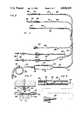
- FIG. 1is a schematic perspective of an irrigation system incorporating the tubing set of the present invention
- FIG. 2is a plan view of the tubing set of the invention
- FIG. 3is an enlarged sectional detail through the pressure relief component of the tubing set in cooperative operable position within a mechanical pressure release valve
- FIG. 4is a detailed illustration of the pressure sensor diaphragm component and the associated pressure sensing line
- FIG. 5is a sectional detail similar to FIG. 4 illustrating another form of pressure diaphragm
- FIG. 6is a perspective detail of the suction-maintaining pigtail on the discharge line.
- FIG. 7is a cross-sectional detail through the trilumen.
- the arthroscopy tubing set 10 of the inventionfunctions as a component of an irrigation system in arthroscopic procedures to channel flow of saline solution from hanging bags or bottles 12 through an arthroscopy pump 14 to the joint or site 16 of the procedure, at a flow rate and pressure set on the pump 14. Ultimately, the flow discharges to an appropriate collector 18.
- the tubing setbe of a trilumen configuration with three parabonded PVC tubes separated at their ends to form three functionally different lines, an inflow line 20, a pressure sensing line 22 and and outflow line 24.
- the inflow line 20includes a capped male luer fitting 26 at the patient end.
- the fitting 26is bonded into a 133" long section of a delivery tube 30 having a 0.187" inside diameter and a 0.312" outside diameter.
- the tube 30is in turn attached to a 13.5" PVC header tube 32 having a 0.375" inside diameter and a 0.5" outside diameter.
- the header tubeconnects to a "Y" connector 34 normally formed or cast from a plastisol.
- Two duplicate PVC supply tubes 36approximately 46" long, extend from the "Y" connector. Each of these tubes has an inside diameter of 0.210" and an outside diameter of 0.312".
- a hand manipulable shut-off clamp 38mounts on each tube 36 approximately 4" to 8" inward from the outer or terminal end thereof.
- the terminal end each of the tubes 36is bonded to a separate bag spike 40 provided with a cap or protector 42 which is removed prior to a piercing engagement of the spike into one of the saline containers 12.
- the header tube 32engageable about the rollers 44 of the peristaltic unit 46 of the pump 14, is of a larger diameter than the delivery tube 30 as the diameter of the header tube is significant in developing the required flow.
- the diameter of the delivery tube 30is desirably smaller for ease in handling, causing less problems in the field of operation.
- the header tubebe of a degree of rigidity within a specific durometer range to facilitate collapse of the tube so as to enable pumping action of the pump rollers 44. If durometer is too high, i.e., the tube is too rigid, the pump will not develop sufficient flow, and will necessarily work harder. If durometer is too soft, the life of the tubing will be reduced. Further, a too soft header tube 32 will also make it difficult to achieve sufficient flow as the tube will not expand to its full diameter when released by the rollers 44. A durometer of 68 has been found particularly satisfactory for a header tube as dimensioned above.
- the pressure sensing line 22includes a capped male luer pressure retaining fitting 50 bonded into one end of a 68 durometer, 3.75" PVC chamber 54 with a 0.312" inside diameter and a 0.438 outside diameter.
- the chamber 54telescopically contains a resiliently collapsible 2.75" balloon diaphragm 56 of an approprite elastomer such as natural or synthetic latex or silicone rubber.
- the diaphragm 56is a pressure transmitter and fluid barrier, and is bonded to and in fluid communication with a length of tube 58 projecting from the end of the chamber 54 remote from the luer fitting 50.
- This tube 58which functions as a pressure tube to transmit sensed pressure, will normally be approximately 144" long with an internal diameter of 0.031" and an outside diameter of 0.135".
- the end of the pressure tube 58 remote from the chamber 54has a capped female luer fitting 60 bonded thereto.
- the pressure transmitting elastomer diaphragmcan be in the nature of a rolling diaphragm which, upon being subjected to pressure at the leading end thereof within chamber 54, will inwardly roll within itself in a controlled manner.
- the male luer fitting 50 on the pressure sensing line 22will be attached to a pressure sensing cannula (not shown).
- the female luer fitting 60will in turn be attached to an appropriate male bulkhead fitting on the pump 14 where the actual pressure measurement is performed.
- the pressure sensing lineis basically dry, restricting liquid to the diaphragm-containing chamber 54 immediately adjacent the operating site.
- the pressure transmission mediumbe air rather than liquid. If liquid were used, any difference in height between the operating site and the measurement transducer at the pump, would reflect itself as an error in measurement. For example, a height difference of one foot would create an error of 22 mm. of mercury.
- the pressure tube 58is kept as small as possible, since it is the compression of the volume of air in this tube, brought about by the collapsing of diaphragm 56 or inward rolling of diaphragm 57, that transmits the pressure. For example, assuming a chamber and tube relationship as shown, the introduction of only 1" of liquid into chamber 54 will result in a pressure change of 200 mm. of mercury in pressure line 58.
- chamber 54Without chamber 54, it would require a displacement along the pressure tube 58 of approximately 30" of water, raising a possibility of introducing significant error, depending on the orientation of pressure line 58.
- the design of the pressure sensing line incorporating a short length of relatively large diameter tubing, as chamber 54, at the operating site, and a long length of very small diameter tubing 58,is highly desirable in providing accurate pressure readings.
- the diaphragm 56 or 57itself insures sterility at the operating site, isolating the operating site from the rest of the tubing 58 which connects to the non-sterile pump 14 and pressure transducer associated therewith.
- the diaphragm 56 or 57also prevents introduction of any liquid into the small diameter pressure tube 58.
- the balloon diaphragm 56 and the rolling diaphragmare each generally in the nature of an elongate closed tubular member extending centrally along substantially the entire length of the tubular chamber 54.
- the relationship of diaphragm size to chamber sizemust be such as to maintain sensitivity within desired parameters.
- the contained volume of the diaphragmmust be sufficient to transmit the maximum required pressure when fully compressed or rolled.
- the material and thickness of the diaphragmmust not introduce any significant pressure drop or error in the measurement.
- the outflow line 24includes a tubular elastomeric adapter 64 of natural or synthetic latex or silicone rubber at the patient end.
- This adapter 64is approximately 4" long and includes a 0.187" inside diameter with a 0.312" outside diameter.
- the outer or free end of the adapteris provided with a protective cap 66 of a distinctive color, preferably blue, providing an easily distinguished visual indication of the patient end of the tubing set.
- the elastomer adapter 64is bonded to a tube 68 approximately 136" long with an inside diameter of 0.187" and an outside diameter of 0.312".
- the tube 68is in turn bonded to a plastisol "Y" 70, the two branches of which are bonded to a pair of parallel tubes approximately 3.5" long.
- the first tube 72is an elastomer tube, for example of latex or silicone rubber, with an inside diameter of 0.250" and a wall thickness of 1/32".
- the second tube 74is PVC tubing with a durometer of 39. This second tube 74 has an inside diameter of 0.250" and an outside diameter of 0.312".
- the two parallel tubes 72 and 74are rejoined by a second plastisol "Y" connector 76 which in turn is bonded to and in communication with a discharge tube 78 approximately 48" long.
- the tube 78has an inside diameter of 0.210" and an outside diameter of 0.312".
- the free remote end of the tube 78is provided with a distinctively colored cap 80, preferably red and easily distinguished from the opposed end cap 66, again to provide a ready and immediate identification of each end of the tubing set.
- the discharge tube 78is provided with one complete coil 82 defining a "pigtail" configuration forming a liquid seal.
- An appropriate cable tie or the like 84is wrapped around the coil to retain the configuration thereof.
- the outflow line 24will be attached to the outflow port or drainage cannula 65, at the operating site, by the tubular latex or silicone rubber adapter 64.
- the parallel branches or tubes 72 and 74, in the outflow line,constitute a portion of the pressure control and relief assembly and are respectively engaged with a mechanical pressure relief valve 86 and a solenoid control valve 88.
- the looped free end of the outflow linewhich facilitates the siphoning effect required in the irrigation system described in the copending application, is placed within a bucket or other drainage container 18 to receive the spent flow.
- both the configuration and dimensions thereofare considered significant in fitting the assembly to the control valve units and routing the tubes 72 and 74 through both the mechanical relief valve 86 and the solenoid control valve 88 without crimping.
- both the mechanical pressure relief valve 86 and the solenoid control valve 88can be provided as components on the overall pump assembly 14. It will also be noted that, as illustrated in FIGS. 1, 2 and 3, the flow in the pressure control and relief assembly is from right to left.
- the PVC tube 74constituting the solenoid control valve tube, is routed through the solenoid valve 88 for cooperation therewith in providing control of the outflow in response to sensed pressure.
- the specific operation of the solenoid valve and the interrelationship between this operation and the sensed pressureis broadly referred to in the copending application.
- the wall thickness, inside diameter and durometer of the solenoid control valve tube 74, as related to the associated solenoid valve,is significant in insuring proper control of flow and proper action of the solenoid, particularly as it is contemplated the tube itself will supply the restoring force for opening the solenoid. Basically, if the inside diameter is too small, or the wall thickness too great, maximum flow capabilities will be diminished. Further, if the wall thickness is too small or the inside diameter too large, an action of the solenoid will not be correct since the restoring force provided by the inherent memory or resiliency of the tube will not be sufficient.
- the design of this tubeis closely associated with the design of the mechanical pressure relief valve 86 itself.
- the pressure relief valve 86includes a reciprocating head 90 elongate relative to the length of the received pressure relief tube 72.
- the direction of flow in the pressure control and relief assembly, and in particular in tube 72is indicated by arrow 91.
- the head 90is spring loaded, by appropriate spring means 92, to engage and pinch off the pressure relief tube against a rigid base 94.
- the pinch closing of the tube 72is in conjunction with a partial constriction of the tube 72 upstream of the pinch area and for the length of the head 90 upstream of the pinch area.
- the actual pinch closing of tube 72is effected by a depending pinch edge portion 96 which projects relative to the tube engaging underface 98 of the head a sufficient distance to provide, as illustrated in FIG. 3, the pinch closing of the tube 72 in conjunction with the desired partial constriction of the tube upstream of the pinch area.
- the total closing force Fis opposed by the resistance of the tubing itself at the pinch tip 96 (TF1), the resistance of the tubing along the extended length of the hammer (TF2), the force applied to the pinch point as a result of the liquid pressure in the tubing (PF1), and the force applied to the extended length of the hammer as a result of the liquid pressure (PF2).
- TF1the resistance of the tubing itself at the pinch tip 96
- TF2the resistance of the tubing along the extended length of the hammer
- PF1the force applied to the pinch point as a result of the liquid pressure in the tubing
- PF2the force applied to the extended length of the hammer as a result of the liquid pressure
- the mechanical valvewill be in equilibrium and any further increase in the pressure will cause the hammer 90 to move up against the force of spring 92, compressing spring 92 and allowing flow through the valve 86 with a resultant reduction of pressure regardless of the position of the solenoid valve on parallel line 74.
- the spring 92is to be designed to have a nearly constant force regardless of its displacement within the operating limits, the valve allowing increase of pressure up to its set point, and then opening so the pressure cannot exceed the set point by any significant amount. It will be appreciated that the characteristics of the tube 72 itself play an important part in the proper operation of the valve.
- the loop or "pigtail” configuration 82in the discharge tube 78 of the discharge line 24 downstream of the pressure control and relief assembly, is significant in ensuring proper operation of the system.
- the "pigtail” 82provides a liquid seal which maintains a column of liquid in the discharge tube extending from the loop 82 to the solenoid valve 88. Without the "pigtail” 82, when the pressure control solenoid 88 closes, the fluid in the discharge tube 78 will drain into the collector or receptacle 18, and air will be introduced into the line. This will result in inaccuracies and delays in reestablishing flow and pressure within desired parameters.
- the "pigtail” 82acting in the manner of a liquid trap or seal, prevents drainage of the line when the solenoid is closed and thus, in a unique manner, solves a particularly vexing problem and provides in effect for a "continuous" intermittent siphon operation.
- the joining of the various tubes in the formation of the individual linesis to be effected in a manner providing for sealed communication between the tubes.
- Thismay entail a direct bonding of the tubes to each other, possibly through a telescopic interfit, or the use of adapters.
- the tube specificationshave been set forth with substantial specificity, and while significant aspects of the invention are attributable thereto, minor tolerances are contemplated. While the majority of the components or tubes of tubing set are of PVC with appropriate wall thicknesses capable of accommodating the internal pressures of the system, the pressure relief valve tube 72 is specifically formed of an elastomer for the enhanced flexibility thereof desired for proper operation of the mechanical pressure relief valve. Similarly, a length of relatively thick walled latex or silicone rubber 64 is provided at the patient end of the outflow line to facilitate an expansion of this line end portion and frictional engagement with an outlet port at the operation site.
- the pumpIn installing the tubing set prior to commencing the arthroscopic procedure, the pump is initially put in the off position and saline bags hung just above the level of the pump. Using sterile techniques, the tubing set is delivered to the scrub nurse. The scrub nurse, in turn, will pass the red-capped equipment end of the tubing set to the circulating nurse. The scrub nurse will then secure the excess tubing and the blue-capped patient-end of the tubing to the sterile field on the draped patient. The circulating nurse will close the clamps 38 on the inflow line 20. The inflow line will then be connected to the pump by engaging the header tube 32 around the pump rollers 44. To facilitate this installation, flow direction indicating arrows can be provided on the pump. The bag spikes will be connected to the saline bags 12.
- the pressure sensing or monitoring line 22will be connected to the appropriate port on the pump and subsequently connected to the patient cannula.
- the relatively stiffer PVC control tube 74is mounted in operative position within the solenoid valve assembly 88.
- the relatively more flexible elastomer pressure relief tube 72is in turn inserted in operative position within the mechanical relief valve unit 86.
- Directional arrowsmay be provided in conjunction with the valve units to insure proper directional positioning of the tubes 72 and 74.
- the looped or "pigtail" end portion of the outlet flow line tube 78is placed within an appropriate collector or liquid collecting receptacle 18 open to the ambient air. The irrigation system, with a new sterile tubing set installed, is now ready for use.
Landscapes
- Health & Medical Sciences (AREA)
- Engineering & Computer Science (AREA)
- Anesthesiology (AREA)
- Biomedical Technology (AREA)
- Heart & Thoracic Surgery (AREA)
- Hematology (AREA)
- Life Sciences & Earth Sciences (AREA)
- Animal Behavior & Ethology (AREA)
- General Health & Medical Sciences (AREA)
- Public Health (AREA)
- Veterinary Medicine (AREA)
- Physics & Mathematics (AREA)
- Fluid Mechanics (AREA)
- Infusion, Injection, And Reservoir Apparatuses (AREA)
- External Artificial Organs (AREA)
Abstract
Description
Claims (20)
Priority Applications (11)
| Application Number | Priority Date | Filing Date | Title |
|---|---|---|---|
| US06/942,271US4820265A (en) | 1986-12-16 | 1986-12-16 | Tubing set |
| CA000549940ACA1277885C (en) | 1986-12-16 | 1987-10-22 | Tubing set |
| JP62305537AJPS63154182A (en) | 1986-12-16 | 1987-12-02 | Tube set |
| EP92112765AEP0528208B1 (en) | 1986-12-16 | 1987-12-03 | Surgical tubing set |
| EP87402750AEP0278188B1 (en) | 1986-12-16 | 1987-12-03 | Tubing set for arthroscopic irrigation |
| DE3751712TDE3751712T2 (en) | 1986-12-16 | 1987-12-03 | Surgical tube set |
| DE87402750TDE3785444T2 (en) | 1986-12-16 | 1987-12-03 | Tube set for arthroscopic irrigation. |
| EP92112766AEP0513858B1 (en) | 1986-12-16 | 1987-12-03 | Tubing set for surgical irrigation systems |
| DE3751711TDE3751711T2 (en) | 1986-12-16 | 1987-12-03 | Tube set for surgical irrigation equipment |
| HK98107026AHK1007692A1 (en) | 1986-12-16 | 1998-06-26 | Surgical tubing set |
| HK98107031AHK1007693A1 (en) | 1986-12-16 | 1998-06-26 | Tubing set for surgical irrigation systems |
Applications Claiming Priority (1)
| Application Number | Priority Date | Filing Date | Title |
|---|---|---|---|
| US06/942,271US4820265A (en) | 1986-12-16 | 1986-12-16 | Tubing set |
Publications (1)
| Publication Number | Publication Date |
|---|---|
| US4820265Atrue US4820265A (en) | 1989-04-11 |
Family
ID=25477839
Family Applications (1)
| Application Number | Title | Priority Date | Filing Date |
|---|---|---|---|
| US06/942,271Expired - LifetimeUS4820265A (en) | 1986-12-16 | 1986-12-16 | Tubing set |
Country Status (6)
| Country | Link |
|---|---|
| US (1) | US4820265A (en) |
| EP (3) | EP0528208B1 (en) |
| JP (1) | JPS63154182A (en) |
| CA (1) | CA1277885C (en) |
| DE (3) | DE3751712T2 (en) |
| HK (2) | HK1007693A1 (en) |
Cited By (159)
| Publication number | Priority date | Publication date | Assignee | Title |
|---|---|---|---|---|
| WO1990007353A1 (en)* | 1989-01-03 | 1990-07-12 | Medical Inventors Corp. | Programmable flexible-tube flow regulator and methods |
| US5037386A (en)* | 1989-11-17 | 1991-08-06 | Minnesota Mining And Manufacturing Company | Pressure sensing scope cannula |
| US5098384A (en)* | 1991-01-23 | 1992-03-24 | Abrams Lawrence M | Pressure-compensated fluid administering apparatus |
| US5098387A (en)* | 1989-10-07 | 1992-03-24 | Peter P. Wiest | Device for irrigation of and aspiration from body cavities |
| US5125891A (en)* | 1987-04-27 | 1992-06-30 | Site Microsurgical Systems, Inc. | Disposable vacuum/peristaltic pump cassette system |
| US5152746A (en)* | 1990-04-30 | 1992-10-06 | Zimmer, Inc. | Low pressure irrigation system |
| US5154700A (en)* | 1990-08-13 | 1992-10-13 | Danby Medical Limited | Arrangement for monitoring fluid flow during intravenous supply to a patient |
| US5176629A (en)* | 1989-07-31 | 1993-01-05 | C. R. Bard, Inc. | Irrigation system for use with endoscopic procedure |
| US5191878A (en)* | 1990-04-12 | 1993-03-09 | Olympus Optical Co., Ltd. | Endoscope device |
| US5322506A (en)* | 1989-07-31 | 1994-06-21 | C. R. Bard, Inc. | Irrigation system with high flow bypass for use with endoscopic procedure |
| WO1994015658A1 (en)* | 1993-01-12 | 1994-07-21 | Minnesota Mining And Manufacturing Company | Irrigation system with tubing cassette |
| US5399160A (en)* | 1991-10-04 | 1995-03-21 | Minnesota Mining And Manufacturing Company | Irrigation tubing set having compliant sections |
| US5454784A (en)* | 1994-06-10 | 1995-10-03 | Zimmer, Inc. | Control valve for a fluid set |
| US5464391A (en)* | 1994-03-03 | 1995-11-07 | Northgate Technologies Inc. | Irrigation system for a surgical site |
| US5505707A (en)* | 1994-12-01 | 1996-04-09 | Northgate Technologies, Inc. | Tubing system with pump for delivering continuous fluid flow or fluid bolus to a surgical site |
| USD370727S (en) | 1995-02-28 | 1996-06-11 | Zimmer, Inc. | Cassette for a lavage pump |
| USD374718S (en) | 1995-06-06 | 1996-10-15 | Minnesota Mining And Manufacturing Company | Cassette for arthroscopic irrigation system tubing set |
| USD377685S (en)* | 1995-09-26 | 1997-01-28 | Haemonetics Corp. | Blood withdrawal and separation set |
| US5605545A (en)* | 1994-05-05 | 1997-02-25 | Northgate Technologies Incorporated | Tubing system for delivering fluid to a surgical site |
| US5616121A (en)* | 1993-08-17 | 1997-04-01 | Mckay; Douglas W. | Method for alleviating pain in a wound |
| US5624394A (en)* | 1994-10-28 | 1997-04-29 | Iolab Corporation | Vacuum system and a method of operating a vacuum system |
| US5626563A (en)* | 1993-01-12 | 1997-05-06 | Minnesota Mining And Manufacturing Company | Irrigation system with tubing cassette |
| US5630799A (en)* | 1991-08-21 | 1997-05-20 | Smith & Nephew Dyonics Inc. | Fluid management system |
| US5636643A (en)* | 1991-11-14 | 1997-06-10 | Wake Forest University | Wound treatment employing reduced pressure |
| US5645081A (en)* | 1991-11-14 | 1997-07-08 | Wake Forest University | Method of treating tissue damage and apparatus for same |
| US5647852A (en)* | 1995-01-31 | 1997-07-15 | Zimmer, Inc. | Lavage system including a cassette assembly |
| US5691478A (en)* | 1995-06-07 | 1997-11-25 | Schneider/Namic | Device and method for remote zeroing of a biological fluid pressure measurement device |
| US5792167A (en)* | 1996-09-13 | 1998-08-11 | Stryker Corporation | Surgical irrigation pump and tool system |
| US5800383A (en)* | 1996-07-17 | 1998-09-01 | Aquarius Medical Corporation | Fluid management system for arthroscopic surgery |
| US5810766A (en)* | 1995-02-28 | 1998-09-22 | Chiron Vision Corporation | Infusion/aspiration apparatus with removable cassette |
| US5810770A (en)* | 1996-12-13 | 1998-09-22 | Stryker Corporation | Fluid management pump system for surgical procedures |
| US5814009A (en)* | 1996-10-11 | 1998-09-29 | Cabot Technology Corporation | Fluid management system and replaceable tubing assembly therefor |
| US5830180A (en)* | 1996-07-17 | 1998-11-03 | Aquarius Medical Corporation | Fluid management system for arthroscopic surgery |
| US5873853A (en)* | 1995-05-23 | 1999-02-23 | Baxter International Inc. | Portable pump apparatus for continuous ambulatory peritoneal dialysis and a method for providing same |
| WO1999033514A1 (en)* | 1997-12-29 | 1999-07-08 | Cobe Laboratories, Inc. | Plunger assembly for measuring occlusion pressure on a flexible tube |
| US5921965A (en)* | 1997-07-07 | 1999-07-13 | New York University | Tubing device for antibiotic administration through central venous catheters |
| US5931808A (en)* | 1992-10-19 | 1999-08-03 | Arthrotek, Inc. | Cassette for endoscope |
| US6024720A (en)* | 1995-07-18 | 2000-02-15 | Aquarius Medical Corporation | Fluid management system for arthroscopic surgery |
| US6129699A (en)* | 1997-10-31 | 2000-10-10 | Sorenson Development, Inc. | Portable persistaltic pump for peritoneal dialysis |
| US6336924B1 (en)* | 1997-12-17 | 2002-01-08 | Nmt Neurosciences Implants S.A. | External biological fluid drainage device |
| US6342061B1 (en) | 1996-09-13 | 2002-01-29 | Barry J. Kauker | Surgical tool with integrated channel for irrigation |
| US6458109B1 (en) | 1998-08-07 | 2002-10-01 | Hill-Rom Services, Inc. | Wound treatment apparatus |
| US20020139419A1 (en)* | 2001-04-02 | 2002-10-03 | Flinchbaugh David E. | Programmable flexible-tube flow regulator and use methods |
| US20020161346A1 (en)* | 2000-11-29 | 2002-10-31 | Lockwood Jeffrey S. | Vacuum therapy and cleansing dressing for wounds |
| US20020183702A1 (en)* | 1999-11-29 | 2002-12-05 | Henley Alan Wayne | Wound treatment apparatus |
| US20030014022A1 (en)* | 2001-07-12 | 2003-01-16 | Lockwood Jeffrey S. | Control of vacuum level rate of change |
| US20030093041A1 (en)* | 2001-10-11 | 2003-05-15 | Risk James R. | Waste container for negative pressure therapy |
| WO2003061754A1 (en)* | 2002-01-18 | 2003-07-31 | Dsu Medical Corporation | Blood flow reversing system |
| US20030208149A1 (en)* | 2000-05-22 | 2003-11-06 | Coffey Arthur C. | Combination sis and vacuum bandage and method |
| US20030225347A1 (en)* | 2002-06-03 | 2003-12-04 | Argenta Louis C. | Directed tissue growth employing reduced pressure |
| US6685681B2 (en) | 2000-11-29 | 2004-02-03 | Hill-Rom Services, Inc. | Vacuum therapy and cleansing dressing for wounds |
| US20040054338A1 (en)* | 2002-09-13 | 2004-03-18 | Farhad Bybordi | Closed wound drainage system |
| US20040073151A1 (en)* | 2002-09-03 | 2004-04-15 | Weston Richard Scott | Reduced pressure treatment system |
| US20040113542A1 (en)* | 2002-12-11 | 2004-06-17 | Applied Materials, Inc. | Low temperature process for passivation applications |
| US20040167463A1 (en)* | 2003-02-21 | 2004-08-26 | Zawacki John A. | Multi-lumen catheter with separate distal tips |
| US20040210187A1 (en)* | 2002-02-07 | 2004-10-21 | Zawacki John A. | Split tip dialysis catheter |
| US20050004534A1 (en)* | 2001-12-26 | 2005-01-06 | Lockwood Jeffery S | Vented vacuum bandage and method |
| US20050010153A1 (en)* | 2001-12-26 | 2005-01-13 | Lockwood Jeffrey S | Vaccum bandage packing |
| US20050054990A1 (en)* | 2003-09-08 | 2005-03-10 | Joanna Graft | Split-tip catheter divider |
| US20050070858A1 (en)* | 2002-04-10 | 2005-03-31 | Lockwood Jeffrey S | Access openings in vacuum bandage |
| US20050085795A1 (en)* | 2002-02-28 | 2005-04-21 | Lockwood Jeffrey S. | External catheter access to vacuum bandage |
| US20050090787A1 (en)* | 1999-11-29 | 2005-04-28 | Risk James R.Jr. | Wound treatment apparatus |
| US6887228B2 (en) | 1998-09-16 | 2005-05-03 | Douglas William McKay | Treatment of wound or joint for relief of pain and promotion of healing |
| US20050171470A1 (en)* | 2004-01-29 | 2005-08-04 | Cannuflow Incorporated | Atraumatic arthroscopic instrument sheath |
| US20050192532A1 (en)* | 2004-01-29 | 2005-09-01 | Kucklick Theodore R. | Atraumatic arthroscopic instrument sheath |
| US20050203452A1 (en)* | 2004-03-09 | 2005-09-15 | Weston Richard S. | Enclosure-based reduced pressure treatment system |
| US20050222544A1 (en)* | 2004-04-05 | 2005-10-06 | Weston Richard S | Flexible reduced pressure treatment appliance |
| US20050222528A1 (en)* | 2004-04-05 | 2005-10-06 | Weston Richard S | Reduced pressure wound cupping treatment system |
| US20050234298A1 (en)* | 2004-01-29 | 2005-10-20 | Cannuflow Incorporated | Atraumatic arthroscopic instrument sheath |
| US20050261642A1 (en)* | 2004-05-21 | 2005-11-24 | Weston Richard S | Flexible reduced pressure treatment appliance |
| US20050277862A1 (en)* | 2004-06-09 | 2005-12-15 | Anand Pj | Splitable tip catheter with bioresorbable adhesive |
| US20060149161A1 (en)* | 2004-12-29 | 2006-07-06 | Wilson Stephen F | System and method for measuring the pressure of a fluid system within a patient |
| US20060161094A1 (en)* | 2005-01-14 | 2006-07-20 | Utterberg David S | 3D clampable valve flow reversing system |
| US20060199997A1 (en)* | 2005-02-24 | 2006-09-07 | Ethicon Endo-Surgery, Inc. | Monitoring of a food intake restriction device |
| US20060211914A1 (en)* | 2005-02-24 | 2006-09-21 | Hassler William L Jr | System and method for determining implanted device positioning and obtaining pressure data |
| US20060211913A1 (en)* | 2005-02-24 | 2006-09-21 | Dlugos Daniel F | Non-invasive pressure measurement in a fluid adjustable restrictive device |
| US20060224163A1 (en)* | 2005-03-30 | 2006-10-05 | Sutton Thomas B | Phaco aspiration flow restrictor with bypass tube |
| US20070032762A1 (en)* | 2005-08-08 | 2007-02-08 | Vogel Richard C | Wound irrigation device |
| US20070032763A1 (en)* | 2005-08-08 | 2007-02-08 | Vogel Richard C | Wound irrigation device pressure monitoring and control system |
| US7198046B1 (en) | 1991-11-14 | 2007-04-03 | Wake Forest University Health Sciences | Wound treatment employing reduced pressure |
| US20070078370A1 (en)* | 2005-06-13 | 2007-04-05 | Smith & Nephew, Inc. *Ew* | Surgical Fluid Management |
| US20070213837A1 (en)* | 2005-02-24 | 2007-09-13 | Ferreri Annie L | System and Method for Determining Implanted Device Orientation |
| US20070235083A1 (en)* | 2005-02-24 | 2007-10-11 | Dlugos Daniel F | Apparatus for Adjustment and Sensing of Gastric Band Pressure |
| US20080033601A1 (en)* | 2006-08-01 | 2008-02-07 | Dream Visions, Llc | Lawn sprinkler play apparatus |
| US20080160535A1 (en)* | 1997-12-15 | 2008-07-03 | Somalogic, Inc. | Methods and Reagents for Detecting Target Binding by Nucleic Acid Ligands |
| US20080271804A1 (en)* | 2007-03-20 | 2008-11-06 | Neogen Technologies, Inc. | Flat-hose assembly for wound drainage system |
| US20080312640A1 (en)* | 2007-06-14 | 2008-12-18 | Sabin Corporation | Modified luer fittings for feeding tube adapter |
| US20090005703A1 (en)* | 2007-06-27 | 2009-01-01 | Codman & Shurtleff, Inc. | Medical Monitor User Interface |
| US20090062607A1 (en)* | 2004-01-29 | 2009-03-05 | Cannuflow Incorporated | Atraumatic Arthroscopic Instrument Sheath |
| US7520872B2 (en) | 2002-09-13 | 2009-04-21 | Neogen Technologies, Inc. | Closed wound drainage system |
| US20090107233A1 (en)* | 2007-10-31 | 2009-04-30 | Codman Shurleff, Inc. | Wireless Flow Sensor |
| US20090112103A1 (en)* | 2007-10-31 | 2009-04-30 | Codman & Shurtleff, Inc. | Wireless Pressure Sensing Shunts |
| US20090112147A1 (en)* | 2007-10-31 | 2009-04-30 | Codman Shurleff, Inc. | Wireless Pressure Setting Indicator |
| US20090112153A1 (en)* | 2007-10-26 | 2009-04-30 | C.R. Bard, Inc. | Split-tip catheter including lateral distal openings |
| US20090118701A1 (en)* | 2003-05-27 | 2009-05-07 | Spire Corporation | Methods and apparatus for inserting multi-lumen split-tip catheters into a blood vessel |
| US20090187259A1 (en)* | 2007-10-10 | 2009-07-23 | Argenta Louis C | Devices and methods for treating spinal cord tissue |
| US20090204052A1 (en)* | 2007-10-17 | 2009-08-13 | Spire Corporation | Manufacture of split tip catheters |
| US20090204079A1 (en)* | 2007-10-17 | 2009-08-13 | Spire Corporation | Catheters with enlarged arterial lumens |
| US20090205189A1 (en)* | 2008-02-15 | 2009-08-20 | Spire Corporation | Manufacture of fixed tip catheters |
| US20090209940A1 (en)* | 2008-02-15 | 2009-08-20 | Spire Corporation | Fusion manufacture of multi-lumen catheters |
| US20090254054A1 (en)* | 2002-10-28 | 2009-10-08 | Smith & Nephew Plc | Apparatus for aspirating, irrigating and cleansing wounds |
| US20090254120A1 (en)* | 2008-01-09 | 2009-10-08 | Argenta Louis C | Device and method for treating central nervous system pathology |
| US20090318887A1 (en)* | 2008-06-19 | 2009-12-24 | Ost Medical, Inc. | Enteral feeding pump system |
| US20100049134A1 (en)* | 2008-08-21 | 2010-02-25 | Schuman Jr Peter J | Pump device, tube device and method for movement and collection of fluid |
| US20100121229A1 (en)* | 2008-07-18 | 2010-05-13 | Argenta Louis C | Apparatus and Method for Cardiac Tissue Modulation by Topical Application of Vacuum to Minimize Cell Death and Damage |
| US7723560B2 (en) | 2001-12-26 | 2010-05-25 | Lockwood Jeffrey S | Wound vacuum therapy dressing kit |
| US7763000B2 (en) | 1999-11-29 | 2010-07-27 | Risk Jr James R | Wound treatment apparatus having a display |
| US7844342B2 (en) | 2008-02-07 | 2010-11-30 | Ethicon Endo-Surgery, Inc. | Powering implantable restriction systems using light |
| US20110015590A1 (en)* | 2009-07-14 | 2011-01-20 | Pal Svedman | Disposable therapeutic device |
| US20110015619A1 (en)* | 2009-07-16 | 2011-01-20 | Pal Svedman | Wound dressings for negative pressure therapy in deep wounds and method of using |
| US20110015585A1 (en)* | 2009-07-14 | 2011-01-20 | Pal Svedman | Method and device for providing intermittent negative pressure wound healing |
| US20110015593A1 (en)* | 2009-07-14 | 2011-01-20 | Pal Svedman | Pump leak monitor for negative pressure wound therapy |
| US20110015589A1 (en)* | 2009-07-14 | 2011-01-20 | Pal Svedman | Disposable therapeutic device |
| US7896856B2 (en) | 2002-08-21 | 2011-03-01 | Robert Petrosenko | Wound packing for preventing wound closure |
| US7927270B2 (en) | 2005-02-24 | 2011-04-19 | Ethicon Endo-Surgery, Inc. | External mechanical pressure sensor for gastric band pressure measurements |
| US7931651B2 (en) | 2006-11-17 | 2011-04-26 | Wake Lake University Health Sciences | External fixation assembly and method of use |
| US20110112574A1 (en)* | 2009-09-11 | 2011-05-12 | Svedman Pal Paul | Device for manual traction wound closure |
| US20110112495A1 (en)* | 2009-10-29 | 2011-05-12 | Pal Svedman | Adhesive Flange Attachment Reinforcer for Suction Port |
| US20110112490A1 (en)* | 2009-07-14 | 2011-05-12 | Vogel David C | Releasably Sealable Wound Dressing for NPWT |
| US20110168857A1 (en)* | 2010-01-08 | 2011-07-14 | Pal Svedman | Adapter for portable negative pressure wound therapy device |
| US8016744B2 (en) | 2005-02-24 | 2011-09-13 | Ethicon Endo-Surgery, Inc. | External pressure-based gastric band adjustment system and method |
| US8034065B2 (en) | 2008-02-26 | 2011-10-11 | Ethicon Endo-Surgery, Inc. | Controlling pressure in adjustable restriction devices |
| US8057492B2 (en) | 2008-02-12 | 2011-11-15 | Ethicon Endo-Surgery, Inc. | Automatically adjusting band system with MEMS pump |
| US8092415B2 (en) | 2007-11-01 | 2012-01-10 | C. R. Bard, Inc. | Catheter assembly including triple lumen tip |
| US8100870B2 (en) | 2007-12-14 | 2012-01-24 | Ethicon Endo-Surgery, Inc. | Adjustable height gastric restriction devices and methods |
| US8114345B2 (en) | 2008-02-08 | 2012-02-14 | Ethicon Endo-Surgery, Inc. | System and method of sterilizing an implantable medical device |
| CN102365106A (en)* | 2009-04-08 | 2012-02-29 | 马林克罗特有限公司 | Multi-drug medical fluid injection system with patient-specific tubing set with usage indicator |
| US8142452B2 (en) | 2007-12-27 | 2012-03-27 | Ethicon Endo-Surgery, Inc. | Controlling pressure in adjustable restriction devices |
| US8152710B2 (en) | 2006-04-06 | 2012-04-10 | Ethicon Endo-Surgery, Inc. | Physiological parameter analysis for an implantable restriction device and a data logger |
| US8187163B2 (en) | 2007-12-10 | 2012-05-29 | Ethicon Endo-Surgery, Inc. | Methods for implanting a gastric restriction device |
| US8187162B2 (en) | 2008-03-06 | 2012-05-29 | Ethicon Endo-Surgery, Inc. | Reorientation port |
| US8192350B2 (en) | 2008-01-28 | 2012-06-05 | Ethicon Endo-Surgery, Inc. | Methods and devices for measuring impedance in a gastric restriction system |
| US8221439B2 (en) | 2008-02-07 | 2012-07-17 | Ethicon Endo-Surgery, Inc. | Powering implantable restriction systems using kinetic motion |
| US8233995B2 (en) | 2008-03-06 | 2012-07-31 | Ethicon Endo-Surgery, Inc. | System and method of aligning an implantable antenna |
| US8292841B2 (en) | 2007-10-26 | 2012-10-23 | C. R. Bard, Inc. | Solid-body catheter including lateral distal openings |
| US8337389B2 (en) | 2008-01-28 | 2012-12-25 | Ethicon Endo-Surgery, Inc. | Methods and devices for diagnosing performance of a gastric restriction system |
| US8377079B2 (en) | 2007-12-27 | 2013-02-19 | Ethicon Endo-Surgery, Inc. | Constant force mechanisms for regulating restriction devices |
| US8377016B2 (en) | 2007-01-10 | 2013-02-19 | Wake Forest University Health Sciences | Apparatus and method for wound treatment employing periodic sub-atmospheric pressure |
| US8480612B2 (en) | 2007-10-31 | 2013-07-09 | DePuy Synthes Products, LLC | Wireless shunts with storage |
| US8569566B2 (en) | 2003-10-28 | 2013-10-29 | Smith & Nephew, Plc | Wound cleansing apparatus in-situ |
| US8591395B2 (en) | 2008-01-28 | 2013-11-26 | Ethicon Endo-Surgery, Inc. | Gastric restriction device data handling devices and methods |
| US8591532B2 (en) | 2008-02-12 | 2013-11-26 | Ethicon Endo-Sugery, Inc. | Automatically adjusting band system |
| US8814829B2 (en) | 2010-08-12 | 2014-08-26 | Baxter International Inc. | Drug delivery device for fluid restricted patients |
| US8870742B2 (en) | 2006-04-06 | 2014-10-28 | Ethicon Endo-Surgery, Inc. | GUI for an implantable restriction device and a data logger |
| US8926592B2 (en) | 2003-10-28 | 2015-01-06 | Smith & Nephew Plc | Wound cleansing apparatus with heat |
| US9233053B2 (en) | 2008-06-19 | 2016-01-12 | Alcor Scientific, Inc. | Enteral feeding pump system |
| USD748252S1 (en) | 2013-02-08 | 2016-01-26 | C. R. Bard, Inc. | Multi-lumen catheter tip |
| CN105561409A (en)* | 2015-12-16 | 2016-05-11 | 天津榕丰科技有限公司 | Automatic urine catheterization device for pressure measurement |
| US9579485B2 (en) | 2007-11-01 | 2017-02-28 | C. R. Bard, Inc. | Catheter assembly including a multi-lumen configuration |
| US9636070B2 (en) | 2013-03-14 | 2017-05-02 | DePuy Synthes Products, Inc. | Methods, systems, and devices for monitoring and displaying medical parameters for a patient |
| US9820916B2 (en) | 2014-07-25 | 2017-11-21 | Covidien Lp | Detection system for flow control apparatus |
| USD809909S1 (en) | 2013-03-15 | 2018-02-13 | Cook Medical Technologies Llc | Tubing clips |
| US10058642B2 (en) | 2004-04-05 | 2018-08-28 | Bluesky Medical Group Incorporated | Reduced pressure treatment system |
| US10113542B2 (en) | 2012-05-24 | 2018-10-30 | Cook Medical Technologies Llc | Peristaltic pump tubing securing system |
| US10258768B2 (en) | 2014-07-14 | 2019-04-16 | C. R. Bard, Inc. | Apparatuses, systems, and methods for inserting catheters having enhanced stiffening and guiding features |
| US10406076B2 (en) | 2008-06-19 | 2019-09-10 | Alcor Scientific, Inc. | Enteral feeding pump system |
| US10583228B2 (en) | 2015-07-28 | 2020-03-10 | J&M Shuler Medical, Inc. | Sub-atmospheric wound therapy systems and methods |
| US11007082B2 (en) | 2014-07-23 | 2021-05-18 | Innovative Therapies Inc. | Foam laminate dressing |
| US11160917B2 (en) | 2020-01-22 | 2021-11-02 | J&M Shuler Medical Inc. | Negative pressure wound therapy barrier |
Families Citing this family (3)
| Publication number | Priority date | Publication date | Assignee | Title |
|---|---|---|---|---|
| IT1297121B1 (en)* | 1997-12-16 | 1999-08-03 | Sviluppo Materiali Spa | SURGICAL DEVICE FOR IRRIGATION AND ASPIRATION OF A PHYSIOLOGICAL SOLUTION |
| BR112019020922A2 (en)* | 2017-04-10 | 2020-11-03 | Coloplast A S | irrigation system for anal and / or stoma irrigation, and method for operating an irrigation system for anal and / or stoma irrigation. |
| RU2741370C2 (en)* | 2019-02-11 | 2021-01-25 | Наталия Анатольевна Бархатова | Loop-like tubular perforated drainage instillator |
Citations (20)
| Publication number | Priority date | Publication date | Assignee | Title |
|---|---|---|---|---|
| US31873A (en)* | 1861-01-01 | 1861-04-02 | James A Cramer | Box for carriage hubs |
| US926197A (en)* | 1908-08-29 | 1909-06-29 | George E Kim | Water-bag syringe. |
| US2478876A (en)* | 1948-05-10 | 1949-08-09 | Ole A Nelson | Automatic intermittent bladder irrigator |
| US2697435A (en)* | 1952-09-22 | 1954-12-21 | Ray Henry Benjamin | Auxiliary blood circuit |
| CA737249A (en)* | 1966-06-28 | Abbott Laboratories | Check valve system | |
| US3313314A (en)* | 1964-05-08 | 1967-04-11 | Burke Vernon | Flexible drain for sinks |
| US3316935A (en)* | 1964-06-24 | 1967-05-02 | Abbott Lab | Flow control clamp |
| US3648687A (en)* | 1969-12-01 | 1972-03-14 | Ramtech | Disposable blood pressure monitor |
| US3912168A (en)* | 1975-01-30 | 1975-10-14 | Teledyne Ind Inc Teledyne Aqua | Irrigation lavage |
| US4062360A (en)* | 1976-04-02 | 1977-12-13 | Bentley Laboratories, Inc. | Atraumatic fluid handling method and apparatus |
| US4077882A (en)* | 1976-09-27 | 1978-03-07 | Ronald Gangemi | Isolating and blood pressure transmitting apparatus for extracorporeal blood treatment system |
| US4226124A (en)* | 1979-04-02 | 1980-10-07 | Baxter Travenol Laboratories, Inc. | Pressure isolator |
| US4273070A (en)* | 1978-09-05 | 1981-06-16 | Bio-Melktechnik Swiss Hoefelmayr & Co. | Milking hose |
| US4314480A (en)* | 1980-07-14 | 1982-02-09 | Baxter Travenol Laboratories, Inc. | Venous pressure isolator |
| US4421505A (en)* | 1982-02-02 | 1983-12-20 | Schwartz Nathan H | Wound irrigation system |
| USRE31873E (en) | 1976-09-08 | 1985-04-30 | Venous catheter device | |
| WO1986000534A1 (en)* | 1983-05-18 | 1986-01-30 | Gambro Ab | A system for the flushing of a body cavity |
| US4604089A (en)* | 1983-08-15 | 1986-08-05 | Codman & Shurtleff, Inc. | Pressure regulated irrigation system for arthroscopy |
| US4648406A (en)* | 1981-02-02 | 1987-03-10 | Michael Ebert | Physiological pressure measuring system |
| US4681559A (en)* | 1985-12-23 | 1987-07-21 | Cordis Corporation | Plural valve three stage pressure relief system |
Family Cites Families (2)
| Publication number | Priority date | Publication date | Assignee | Title |
|---|---|---|---|---|
| US3033194A (en)* | 1960-11-08 | 1962-05-08 | Henry E Lippert | Biopsy capsule and apparatus |
| DE3332723A1 (en)* | 1983-09-10 | 1985-03-28 | Michael 6430 Bad Hersfeld Post | Stomach irrigation apparatus |
- 1986
- 1986-12-16USUS06/942,271patent/US4820265A/ennot_activeExpired - Lifetime
- 1987
- 1987-10-22CACA000549940Apatent/CA1277885C/ennot_activeExpired - Lifetime
- 1987-12-02JPJP62305537Apatent/JPS63154182A/enactivePending
- 1987-12-03EPEP92112765Apatent/EP0528208B1/ennot_activeExpired - Lifetime
- 1987-12-03EPEP92112766Apatent/EP0513858B1/ennot_activeExpired - Lifetime
- 1987-12-03DEDE3751712Tpatent/DE3751712T2/ennot_activeExpired - Lifetime
- 1987-12-03DEDE3751711Tpatent/DE3751711T2/ennot_activeExpired - Lifetime
- 1987-12-03DEDE87402750Tpatent/DE3785444T2/ennot_activeExpired - Lifetime
- 1987-12-03EPEP87402750Apatent/EP0278188B1/ennot_activeExpired - Lifetime
- 1998
- 1998-06-26HKHK98107031Apatent/HK1007693A1/ennot_activeIP Right Cessation
- 1998-06-26HKHK98107026Apatent/HK1007692A1/ennot_activeIP Right Cessation
Patent Citations (21)
| Publication number | Priority date | Publication date | Assignee | Title |
|---|---|---|---|---|
| CA737249A (en)* | 1966-06-28 | Abbott Laboratories | Check valve system | |
| US31873A (en)* | 1861-01-01 | 1861-04-02 | James A Cramer | Box for carriage hubs |
| US926197A (en)* | 1908-08-29 | 1909-06-29 | George E Kim | Water-bag syringe. |
| US2478876A (en)* | 1948-05-10 | 1949-08-09 | Ole A Nelson | Automatic intermittent bladder irrigator |
| US2697435A (en)* | 1952-09-22 | 1954-12-21 | Ray Henry Benjamin | Auxiliary blood circuit |
| US3313314A (en)* | 1964-05-08 | 1967-04-11 | Burke Vernon | Flexible drain for sinks |
| US3316935A (en)* | 1964-06-24 | 1967-05-02 | Abbott Lab | Flow control clamp |
| US3648687A (en)* | 1969-12-01 | 1972-03-14 | Ramtech | Disposable blood pressure monitor |
| US3912168A (en)* | 1975-01-30 | 1975-10-14 | Teledyne Ind Inc Teledyne Aqua | Irrigation lavage |
| US4062360A (en)* | 1976-04-02 | 1977-12-13 | Bentley Laboratories, Inc. | Atraumatic fluid handling method and apparatus |
| USRE31873E (en) | 1976-09-08 | 1985-04-30 | Venous catheter device | |
| USRE31873F1 (en) | 1976-09-08 | 1988-11-15 | Venous catheter device | |
| US4077882A (en)* | 1976-09-27 | 1978-03-07 | Ronald Gangemi | Isolating and blood pressure transmitting apparatus for extracorporeal blood treatment system |
| US4273070A (en)* | 1978-09-05 | 1981-06-16 | Bio-Melktechnik Swiss Hoefelmayr & Co. | Milking hose |
| US4226124A (en)* | 1979-04-02 | 1980-10-07 | Baxter Travenol Laboratories, Inc. | Pressure isolator |
| US4314480A (en)* | 1980-07-14 | 1982-02-09 | Baxter Travenol Laboratories, Inc. | Venous pressure isolator |
| US4648406A (en)* | 1981-02-02 | 1987-03-10 | Michael Ebert | Physiological pressure measuring system |
| US4421505A (en)* | 1982-02-02 | 1983-12-20 | Schwartz Nathan H | Wound irrigation system |
| WO1986000534A1 (en)* | 1983-05-18 | 1986-01-30 | Gambro Ab | A system for the flushing of a body cavity |
| US4604089A (en)* | 1983-08-15 | 1986-08-05 | Codman & Shurtleff, Inc. | Pressure regulated irrigation system for arthroscopy |
| US4681559A (en)* | 1985-12-23 | 1987-07-21 | Cordis Corporation | Plural valve three stage pressure relief system |
Cited By (346)
| Publication number | Priority date | Publication date | Assignee | Title |
|---|---|---|---|---|
| US5125891A (en)* | 1987-04-27 | 1992-06-30 | Site Microsurgical Systems, Inc. | Disposable vacuum/peristaltic pump cassette system |
| WO1990007353A1 (en)* | 1989-01-03 | 1990-07-12 | Medical Inventors Corp. | Programmable flexible-tube flow regulator and methods |
| US5176629A (en)* | 1989-07-31 | 1993-01-05 | C. R. Bard, Inc. | Irrigation system for use with endoscopic procedure |
| US5322506A (en)* | 1989-07-31 | 1994-06-21 | C. R. Bard, Inc. | Irrigation system with high flow bypass for use with endoscopic procedure |
| US5098387A (en)* | 1989-10-07 | 1992-03-24 | Peter P. Wiest | Device for irrigation of and aspiration from body cavities |
| DE4034143C2 (en)* | 1989-11-17 | 2000-11-30 | Linvatec Corp | Arthroscopic cannula for pressure measurement |
| US5037386A (en)* | 1989-11-17 | 1991-08-06 | Minnesota Mining And Manufacturing Company | Pressure sensing scope cannula |
| US5191878A (en)* | 1990-04-12 | 1993-03-09 | Olympus Optical Co., Ltd. | Endoscope device |
| US5152746A (en)* | 1990-04-30 | 1992-10-06 | Zimmer, Inc. | Low pressure irrigation system |
| US5154700A (en)* | 1990-08-13 | 1992-10-13 | Danby Medical Limited | Arrangement for monitoring fluid flow during intravenous supply to a patient |
| US5098384A (en)* | 1991-01-23 | 1992-03-24 | Abrams Lawrence M | Pressure-compensated fluid administering apparatus |
| WO1992012742A1 (en)* | 1991-01-23 | 1992-08-06 | Abrams Lawrence M | Pressure-compensated fluid administering apparatus |
| US5882339A (en)* | 1991-08-21 | 1999-03-16 | Smith & Nephew, Inc. | Fluid management system |
| US5643302A (en)* | 1991-08-21 | 1997-07-01 | Smith & Nephew Dyonics Inc. | Fluid management system |
| US5643203A (en)* | 1991-08-21 | 1997-07-01 | Smith & Nephew Dyonics Inc. | Fluid management system |
| US5630798A (en)* | 1991-08-21 | 1997-05-20 | Smith & Nephew Dyonics Inc. | Fluid management system |
| US5630799A (en)* | 1991-08-21 | 1997-05-20 | Smith & Nephew Dyonics Inc. | Fluid management system |
| US5840060A (en)* | 1991-08-21 | 1998-11-24 | Smith & Nephew, Inc. | Fluid management system |
| US5399160A (en)* | 1991-10-04 | 1995-03-21 | Minnesota Mining And Manufacturing Company | Irrigation tubing set having compliant sections |
| US7198046B1 (en) | 1991-11-14 | 2007-04-03 | Wake Forest University Health Sciences | Wound treatment employing reduced pressure |
| US5636643A (en)* | 1991-11-14 | 1997-06-10 | Wake Forest University | Wound treatment employing reduced pressure |
| US7216651B2 (en) | 1991-11-14 | 2007-05-15 | Wake Forest University Health Sciences | Wound treatment employing reduced pressure |
| US5645081A (en)* | 1991-11-14 | 1997-07-08 | Wake Forest University | Method of treating tissue damage and apparatus for same |
| US5931808A (en)* | 1992-10-19 | 1999-08-03 | Arthrotek, Inc. | Cassette for endoscope |
| US5628731A (en)* | 1993-01-12 | 1997-05-13 | Minnesota Mining And Manufacturing Company | Irrigation system with tubing cassette |
| US5403277A (en)* | 1993-01-12 | 1995-04-04 | Minnesota Mining And Manufacturing Company | Irrigation system with tubing cassette |
| WO1994015658A1 (en)* | 1993-01-12 | 1994-07-21 | Minnesota Mining And Manufacturing Company | Irrigation system with tubing cassette |
| US5626563A (en)* | 1993-01-12 | 1997-05-06 | Minnesota Mining And Manufacturing Company | Irrigation system with tubing cassette |
| US5616121A (en)* | 1993-08-17 | 1997-04-01 | Mckay; Douglas W. | Method for alleviating pain in a wound |
| US5464391A (en)* | 1994-03-03 | 1995-11-07 | Northgate Technologies Inc. | Irrigation system for a surgical site |
| US5605545A (en)* | 1994-05-05 | 1997-02-25 | Northgate Technologies Incorporated | Tubing system for delivering fluid to a surgical site |
| US5454784A (en)* | 1994-06-10 | 1995-10-03 | Zimmer, Inc. | Control valve for a fluid set |
| US5795328A (en)* | 1994-10-28 | 1998-08-18 | Iolab Corporation | Vacuum system and a method of operating a vacuum system |
| US5624394A (en)* | 1994-10-28 | 1997-04-29 | Iolab Corporation | Vacuum system and a method of operating a vacuum system |
| US5505707A (en)* | 1994-12-01 | 1996-04-09 | Northgate Technologies, Inc. | Tubing system with pump for delivering continuous fluid flow or fluid bolus to a surgical site |
| US5647852A (en)* | 1995-01-31 | 1997-07-15 | Zimmer, Inc. | Lavage system including a cassette assembly |
| USD370727S (en) | 1995-02-28 | 1996-06-11 | Zimmer, Inc. | Cassette for a lavage pump |
| US5810766A (en)* | 1995-02-28 | 1998-09-22 | Chiron Vision Corporation | Infusion/aspiration apparatus with removable cassette |
| US6196992B1 (en) | 1995-05-23 | 2001-03-06 | Baxter International Inc. | Portable pump apparatus for continuous ambulatory peritoneal dialysis and a method for providing same |
| US5984891A (en)* | 1995-05-23 | 1999-11-16 | Baxter International Inc. | Portable pump apparatus for continuous ambulatory peritoneal dialysis and a method for providing same |
| US5873853A (en)* | 1995-05-23 | 1999-02-23 | Baxter International Inc. | Portable pump apparatus for continuous ambulatory peritoneal dialysis and a method for providing same |
| USD374718S (en) | 1995-06-06 | 1996-10-15 | Minnesota Mining And Manufacturing Company | Cassette for arthroscopic irrigation system tubing set |
| US5691478A (en)* | 1995-06-07 | 1997-11-25 | Schneider/Namic | Device and method for remote zeroing of a biological fluid pressure measurement device |
| US6024720A (en)* | 1995-07-18 | 2000-02-15 | Aquarius Medical Corporation | Fluid management system for arthroscopic surgery |
| USD377685S (en)* | 1995-09-26 | 1997-01-28 | Haemonetics Corp. | Blood withdrawal and separation set |
| US5830180A (en)* | 1996-07-17 | 1998-11-03 | Aquarius Medical Corporation | Fluid management system for arthroscopic surgery |
| US5800383A (en)* | 1996-07-17 | 1998-09-01 | Aquarius Medical Corporation | Fluid management system for arthroscopic surgery |
| US5928257A (en)* | 1996-09-13 | 1999-07-27 | Stryker Corporation | Surgical irrigation pump and tool system |
| US5792167A (en)* | 1996-09-13 | 1998-08-11 | Stryker Corporation | Surgical irrigation pump and tool system |
| US6342061B1 (en) | 1996-09-13 | 2002-01-29 | Barry J. Kauker | Surgical tool with integrated channel for irrigation |
| US6007556A (en)* | 1996-09-13 | 1999-12-28 | Stryker Corporation | Surgical irrigation pump and tool system |
| US5814009A (en)* | 1996-10-11 | 1998-09-29 | Cabot Technology Corporation | Fluid management system and replaceable tubing assembly therefor |
| US6234992B1 (en) | 1996-11-01 | 2001-05-22 | Sorenson Development, Inc. | Portable peristaltic pump for peritoneal dialysis |
| US5810770A (en)* | 1996-12-13 | 1998-09-22 | Stryker Corporation | Fluid management pump system for surgical procedures |
| US5921965A (en)* | 1997-07-07 | 1999-07-13 | New York University | Tubing device for antibiotic administration through central venous catheters |
| US6129699A (en)* | 1997-10-31 | 2000-10-10 | Sorenson Development, Inc. | Portable persistaltic pump for peritoneal dialysis |
| US20080160535A1 (en)* | 1997-12-15 | 2008-07-03 | Somalogic, Inc. | Methods and Reagents for Detecting Target Binding by Nucleic Acid Ligands |
| US6336924B1 (en)* | 1997-12-17 | 2002-01-08 | Nmt Neurosciences Implants S.A. | External biological fluid drainage device |
| WO1999033514A1 (en)* | 1997-12-29 | 1999-07-08 | Cobe Laboratories, Inc. | Plunger assembly for measuring occlusion pressure on a flexible tube |
| US6458109B1 (en) | 1998-08-07 | 2002-10-01 | Hill-Rom Services, Inc. | Wound treatment apparatus |
| US8540687B2 (en) | 1998-08-07 | 2013-09-24 | Kci Licensing, Inc. | Wound treatment apparatus |
| US7276051B1 (en) | 1998-08-07 | 2007-10-02 | Hill-Rom Services, Inc. | Wound treatment apparatus |
| US7794438B2 (en) | 1998-08-07 | 2010-09-14 | Alan Wayne Henley | Wound treatment apparatus |
| US6887228B2 (en) | 1998-09-16 | 2005-05-03 | Douglas William McKay | Treatment of wound or joint for relief of pain and promotion of healing |
| US7763000B2 (en) | 1999-11-29 | 2010-07-27 | Risk Jr James R | Wound treatment apparatus having a display |
| US20050090787A1 (en)* | 1999-11-29 | 2005-04-28 | Risk James R.Jr. | Wound treatment apparatus |
| US20020183702A1 (en)* | 1999-11-29 | 2002-12-05 | Henley Alan Wayne | Wound treatment apparatus |
| US7678090B2 (en) | 1999-11-29 | 2010-03-16 | Risk Jr James R | Wound treatment apparatus |
| US8021348B2 (en) | 1999-11-29 | 2011-09-20 | Kci Medical Resources | Wound treatment apparatus |
| US6755807B2 (en) | 1999-11-29 | 2004-06-29 | Hill-Rom Services, Inc. | Wound treatment apparatus |
| US6800074B2 (en) | 1999-11-29 | 2004-10-05 | Hill-Rom Services, Inc. | Wound treatment apparatus |
| US8747887B2 (en) | 2000-05-22 | 2014-06-10 | Kci Medical Resources | Combination SIS and vacuum bandage and method |
| US7910791B2 (en) | 2000-05-22 | 2011-03-22 | Coffey Arthur C | Combination SIS and vacuum bandage and method |
| US20030208149A1 (en)* | 2000-05-22 | 2003-11-06 | Coffey Arthur C. | Combination sis and vacuum bandage and method |
| US8246592B2 (en) | 2000-11-29 | 2012-08-21 | Kci Medical Resources | Vacuum therapy and cleansing dressing for wounds |
| US6855135B2 (en) | 2000-11-29 | 2005-02-15 | Hill-Rom Services, Inc. | Vacuum therapy and cleansing dressing for wounds |
| US7988680B2 (en) | 2000-11-29 | 2011-08-02 | Kci Medical Resources | Vacuum therapy and cleansing dressing for wounds |
| US20020161346A1 (en)* | 2000-11-29 | 2002-10-31 | Lockwood Jeffrey S. | Vacuum therapy and cleansing dressing for wounds |
| US10357404B2 (en) | 2000-11-29 | 2019-07-23 | Kci Medical Resources Unlimited Company | Vacuum therapy and cleansing dressing for wounds |
| US7867206B2 (en) | 2000-11-29 | 2011-01-11 | Kci Licensing, Inc. | Vacuum therapy and cleansing dressing for wounds |
| US6752794B2 (en) | 2000-11-29 | 2004-06-22 | Hill-Rom Services, Inc. | Vacuum therapy and cleansing dressing for wounds |
| US6685681B2 (en) | 2000-11-29 | 2004-02-03 | Hill-Rom Services, Inc. | Vacuum therapy and cleansing dressing for wounds |
| US20020139419A1 (en)* | 2001-04-02 | 2002-10-03 | Flinchbaugh David E. | Programmable flexible-tube flow regulator and use methods |
| US20030014022A1 (en)* | 2001-07-12 | 2003-01-16 | Lockwood Jeffrey S. | Control of vacuum level rate of change |
| US7022113B2 (en) | 2001-07-12 | 2006-04-04 | Hill-Rom Services, Inc. | Control of vacuum level rate of change |
| US20030093041A1 (en)* | 2001-10-11 | 2003-05-15 | Risk James R. | Waste container for negative pressure therapy |
| US7927318B2 (en) | 2001-10-11 | 2011-04-19 | Risk Jr James Robert | Waste container for negative pressure therapy |
| US7723560B2 (en) | 2001-12-26 | 2010-05-25 | Lockwood Jeffrey S | Wound vacuum therapy dressing kit |
| US20050004534A1 (en)* | 2001-12-26 | 2005-01-06 | Lockwood Jeffery S | Vented vacuum bandage and method |
| US20050010153A1 (en)* | 2001-12-26 | 2005-01-13 | Lockwood Jeffrey S | Vaccum bandage packing |
| US7195624B2 (en) | 2001-12-26 | 2007-03-27 | Hill-Rom Services, Inc. | Vented vacuum bandage with irrigation for wound healing and method |
| US8350116B2 (en) | 2001-12-26 | 2013-01-08 | Kci Medical Resources | Vacuum bandage packing |
| US7896864B2 (en) | 2001-12-26 | 2011-03-01 | Lockwood Jeffrey S | Vented vacuum bandage with irrigation for wound healing and method |
| US7534927B2 (en) | 2001-12-26 | 2009-05-19 | Hill-Rom Services, Inc. | Vacuum bandage packing |
| US6695807B2 (en)* | 2002-01-18 | 2004-02-24 | Dsu Medical, Inc. | Blood flow reversing system |
| WO2003061754A1 (en)* | 2002-01-18 | 2003-07-31 | Dsu Medical Corporation | Blood flow reversing system |
| US8021321B2 (en) | 2002-02-07 | 2011-09-20 | C. R. Bard, Inc. | Split tip dialysis catheter |
| US20040210187A1 (en)* | 2002-02-07 | 2004-10-21 | Zawacki John A. | Split tip dialysis catheter |
| US20050085795A1 (en)* | 2002-02-28 | 2005-04-21 | Lockwood Jeffrey S. | External catheter access to vacuum bandage |
| US7338482B2 (en) | 2002-02-28 | 2008-03-04 | Hill-Rom Services, Inc. | External catheter access to vacuum bandage |
| US20050070858A1 (en)* | 2002-04-10 | 2005-03-31 | Lockwood Jeffrey S | Access openings in vacuum bandage |
| US8168848B2 (en) | 2002-04-10 | 2012-05-01 | KCI Medical Resources, Inc. | Access openings in vacuum bandage |
| US20030225347A1 (en)* | 2002-06-03 | 2003-12-04 | Argenta Louis C. | Directed tissue growth employing reduced pressure |
| US7896856B2 (en) | 2002-08-21 | 2011-03-01 | Robert Petrosenko | Wound packing for preventing wound closure |
| US11376356B2 (en) | 2002-09-03 | 2022-07-05 | Smith & Nephew, Inc. | Reduced pressure treatment system |
| US20110077604A1 (en)* | 2002-09-03 | 2011-03-31 | Bluesky Medical Group, Inc. | Reduced pressure treatment system |
| US11298454B2 (en) | 2002-09-03 | 2022-04-12 | Smith & Nephew, Inc. | Reduced pressure treatment system |
| US8545464B2 (en) | 2002-09-03 | 2013-10-01 | Bluesky Medical Group Incorporated | Reduced pressure treatment system |
| US8628505B2 (en) | 2002-09-03 | 2014-01-14 | Bluesky Medical Group Incorporated | Reduced pressure treatment system |
| US7846141B2 (en) | 2002-09-03 | 2010-12-07 | Bluesky Medical Group Incorporated | Reduced pressure treatment system |
| US8062273B2 (en) | 2002-09-03 | 2011-11-22 | Bluesky Medical Group Incorporated | Reduced pressure treatment system |
| US20040073151A1 (en)* | 2002-09-03 | 2004-04-15 | Weston Richard Scott | Reduced pressure treatment system |
| US10265445B2 (en) | 2002-09-03 | 2019-04-23 | Smith & Nephew, Inc. | Reduced pressure treatment system |
| US9211365B2 (en) | 2002-09-03 | 2015-12-15 | Bluesky Medical Group, Inc. | Reduced pressure treatment system |
| US20050261643A1 (en)* | 2002-09-13 | 2005-11-24 | Farhad Bybordi | Closed wound drainage system |
| US8034038B2 (en) | 2002-09-13 | 2011-10-11 | Neogen Technologies, Inc. | Closed wound drainage system |
| US6979324B2 (en) | 2002-09-13 | 2005-12-27 | Neogen Technologies, Inc. | Closed wound drainage system |
| US20090204085A1 (en)* | 2002-09-13 | 2009-08-13 | Neogen Technologies, Inc. | Closed wound drainage system |
| US20040054338A1 (en)* | 2002-09-13 | 2004-03-18 | Farhad Bybordi | Closed wound drainage system |
| US7520872B2 (en) | 2002-09-13 | 2009-04-21 | Neogen Technologies, Inc. | Closed wound drainage system |
| US7731702B2 (en) | 2002-09-13 | 2010-06-08 | Neogen Technologies, Inc. | Closed wound drainage system |
| US9844474B2 (en) | 2002-10-28 | 2017-12-19 | Smith & Nephew Plc | Apparatus for aspirating, irrigating and cleansing wounds |
| US20110087176A2 (en)* | 2002-10-28 | 2011-04-14 | Smith & Nephew Plc | Apparatus for aspirating, irrigating and cleansing wounds |
| US10842678B2 (en) | 2002-10-28 | 2020-11-24 | Smith & Nephew Plc | Apparatus for aspirating, irrigating and cleansing wounds |
| US8398614B2 (en) | 2002-10-28 | 2013-03-19 | Smith & Nephew Plc | Apparatus for aspirating, irrigating and cleansing wounds |
| US10278869B2 (en) | 2002-10-28 | 2019-05-07 | Smith & Nephew Plc | Apparatus for aspirating, irrigating and cleansing wounds |
| US8834451B2 (en) | 2002-10-28 | 2014-09-16 | Smith & Nephew Plc | In-situ wound cleansing apparatus |
| US20090254054A1 (en)* | 2002-10-28 | 2009-10-08 | Smith & Nephew Plc | Apparatus for aspirating, irrigating and cleansing wounds |
| US9844473B2 (en) | 2002-10-28 | 2017-12-19 | Smith & Nephew Plc | Apparatus for aspirating, irrigating and cleansing wounds |
| US9205001B2 (en) | 2002-10-28 | 2015-12-08 | Smith & Nephew Plc | Apparatus for aspirating, irrigating and cleansing wounds |
| US20040113542A1 (en)* | 2002-12-11 | 2004-06-17 | Applied Materials, Inc. | Low temperature process for passivation applications |
| US7393339B2 (en) | 2003-02-21 | 2008-07-01 | C. R. Bard, Inc. | Multi-lumen catheter with separate distal tips |
| US8808227B2 (en) | 2003-02-21 | 2014-08-19 | C. R. Bard, Inc. | Multi-lumen catheter with separate distal tips |
| US9387304B2 (en) | 2003-02-21 | 2016-07-12 | C.R. Bard, Inc. | Multi-lumen catheter with separate distal tips |
| US20040167463A1 (en)* | 2003-02-21 | 2004-08-26 | Zawacki John A. | Multi-lumen catheter with separate distal tips |
| US8152951B2 (en) | 2003-02-21 | 2012-04-10 | C. R. Bard, Inc. | Multi-lumen catheter with separate distal tips |
| US10105514B2 (en) | 2003-05-27 | 2018-10-23 | Bard Access Systems, Inc. | Methods and apparatus for inserting multi-lumen split-tip catheters into a blood vessel |
| US9572956B2 (en) | 2003-05-27 | 2017-02-21 | Bard Access Systems, Inc. | Methods and apparatus for inserting multi-lumen split-tip catheters into a blood vessel |
| US8206371B2 (en) | 2003-05-27 | 2012-06-26 | Bard Access Systems, Inc. | Methods and apparatus for inserting multi-lumen split-tip catheters into a blood vessel |
| US8597275B2 (en) | 2003-05-27 | 2013-12-03 | Bard Access Systems, Inc. | Methods and apparatus for inserting multi-lumen split-tip catheters into a blood vessel |
| US20090118701A1 (en)* | 2003-05-27 | 2009-05-07 | Spire Corporation | Methods and apparatus for inserting multi-lumen split-tip catheters into a blood vessel |
| US10806895B2 (en) | 2003-05-27 | 2020-10-20 | Bard Access Systems, Inc. | Methods and apparatus for inserting multi-lumen split-tip catheters into a blood vessel |
| US20050054990A1 (en)* | 2003-09-08 | 2005-03-10 | Joanna Graft | Split-tip catheter divider |
| US9289542B2 (en) | 2003-10-28 | 2016-03-22 | Smith & Nephew Plc | Wound cleansing apparatus |
| US9446178B2 (en) | 2003-10-28 | 2016-09-20 | Smith & Nephew Plc | Wound cleansing apparatus in-situ |
| US9452248B2 (en) | 2003-10-28 | 2016-09-27 | Smith & Nephew Plc | Wound cleansing apparatus in-situ |
| US8569566B2 (en) | 2003-10-28 | 2013-10-29 | Smith & Nephew, Plc | Wound cleansing apparatus in-situ |
| US9616208B2 (en) | 2003-10-28 | 2017-04-11 | Smith & Nephew Plc | Wound cleansing apparatus |
| US8926592B2 (en) | 2003-10-28 | 2015-01-06 | Smith & Nephew Plc | Wound cleansing apparatus with heat |
| US20140364871A1 (en)* | 2004-01-29 | 2014-12-11 | Cannuflow, Inc. | Atraumatic arthroscopic instrument sheath |
| US20090082628A1 (en)* | 2004-01-29 | 2009-03-26 | Cannuflow, Inc. | Atraumatic Arthroscopic Instrument Sheath |
| US20160278619A1 (en)* | 2004-01-29 | 2016-09-29 | Cannuflow, Inc. | Atraumatic arthroscopic instrument sheath |
| US8167790B2 (en) | 2004-01-29 | 2012-05-01 | Cannuflow, Inc. | Atraumatic arthroscopic instrument sheath |
| US8740773B2 (en) | 2004-01-29 | 2014-06-03 | Cannuflow, Inc. | Atraumatic arthroscopic instrument sheath |
| US8118731B2 (en) | 2004-01-29 | 2012-02-21 | Cannuflow, Inc. | Atraumatic arthroscopic instrument sheath |
| US20090182201A1 (en)* | 2004-01-29 | 2009-07-16 | Cannuflow Incorporated | Atraumatic Arthroscopic Instrument Sheath |
| US9364204B2 (en)* | 2004-01-29 | 2016-06-14 | Cannuflow, Inc. | Atraumatic arthroscopic instrument sheath |
| US8758227B2 (en) | 2004-01-29 | 2014-06-24 | Cannuflow, Inc. | Atraumatic arthroscopic instrument sheath and method |
| US8814780B2 (en) | 2004-01-29 | 2014-08-26 | Cannuflow, Inc. | Atraumatic arthroscopic instrument sheath |
| US8821387B2 (en) | 2004-01-29 | 2014-09-02 | Cannuflow, Inc. | Atraumatic arthroscopic instrument sheath |
| US7435214B2 (en) | 2004-01-29 | 2008-10-14 | Cannuflow, Inc. | Atraumatic arthroscopic instrument sheath |
| US20050234298A1 (en)* | 2004-01-29 | 2005-10-20 | Cannuflow Incorporated | Atraumatic arthroscopic instrument sheath |
| US7413542B2 (en) | 2004-01-29 | 2008-08-19 | Cannuflow, Inc. | Atraumatic arthroscopic instrument sheath |
| US20050192532A1 (en)* | 2004-01-29 | 2005-09-01 | Kucklick Theodore R. | Atraumatic arthroscopic instrument sheath |
| US20050171470A1 (en)* | 2004-01-29 | 2005-08-04 | Cannuflow Incorporated | Atraumatic arthroscopic instrument sheath |
| US8012083B2 (en) | 2004-01-29 | 2011-09-06 | Cannuflow, Inc. | Atraumatic arthroscopic instrument sheath |
| US7998061B2 (en) | 2004-01-29 | 2011-08-16 | Cannuflow, Inc. | Atraumatic arthroscopic instrument sheath and method |
| US7500947B2 (en) | 2004-01-29 | 2009-03-10 | Cannonflow, Inc. | Atraumatic arthroscopic instrument sheath |
| US20090062607A1 (en)* | 2004-01-29 | 2009-03-05 | Cannuflow Incorporated | Atraumatic Arthroscopic Instrument Sheath |
| US20090043165A1 (en)* | 2004-01-29 | 2009-02-12 | Cannuflow Incorporated | Atraumatic Arthroscopic Instrument Sheath |
| US9186044B2 (en) | 2004-01-29 | 2015-11-17 | Cannuflow, Inc. | Atraumatic arthroscopic instrument sheath |
| US8100887B2 (en) | 2004-03-09 | 2012-01-24 | Bluesky Medical Group Incorporated | Enclosure-based reduced pressure treatment system |
| US20050203452A1 (en)* | 2004-03-09 | 2005-09-15 | Weston Richard S. | Enclosure-based reduced pressure treatment system |
| US8708998B2 (en) | 2004-03-09 | 2014-04-29 | Bluesky Medical Group, Inc. | Enclosure-based reduced pressure treatment system |
| US20090192499A1 (en)* | 2004-03-09 | 2009-07-30 | Richard Scott Weston | Enclosure-based reduced pressure treatment system |
| US20050222544A1 (en)* | 2004-04-05 | 2005-10-06 | Weston Richard S | Flexible reduced pressure treatment appliance |
| US10842919B2 (en) | 2004-04-05 | 2020-11-24 | Smith & Nephew, Inc. | Reduced pressure treatment system |
| US10058642B2 (en) | 2004-04-05 | 2018-08-28 | Bluesky Medical Group Incorporated | Reduced pressure treatment system |
| US11730874B2 (en) | 2004-04-05 | 2023-08-22 | Smith & Nephew, Inc. | Reduced pressure treatment appliance |
| US7909805B2 (en) | 2004-04-05 | 2011-03-22 | Bluesky Medical Group Incorporated | Flexible reduced pressure treatment appliance |
| US20050222528A1 (en)* | 2004-04-05 | 2005-10-06 | Weston Richard S | Reduced pressure wound cupping treatment system |
| US9198801B2 (en) | 2004-04-05 | 2015-12-01 | Bluesky Medical Group, Inc. | Flexible reduced pressure treatment appliance |
| US7708724B2 (en) | 2004-04-05 | 2010-05-04 | Blue Sky Medical Group Incorporated | Reduced pressure wound cupping treatment system |
| US8449509B2 (en) | 2004-04-05 | 2013-05-28 | Bluesky Medical Group Incorporated | Flexible reduced pressure treatment appliance |
| US10363346B2 (en) | 2004-04-05 | 2019-07-30 | Smith & Nephew, Inc. | Flexible reduced pressure treatment appliance |
| US10350339B2 (en) | 2004-04-05 | 2019-07-16 | Smith & Nephew, Inc. | Flexible reduced pressure treatment appliance |
| US10105471B2 (en) | 2004-04-05 | 2018-10-23 | Smith & Nephew, Inc. | Reduced pressure treatment system |
| US10207035B2 (en) | 2004-05-21 | 2019-02-19 | Smith & Nephew, Inc. | Flexible reduced pressure treatment appliance |
| US8062272B2 (en) | 2004-05-21 | 2011-11-22 | Bluesky Medical Group Incorporated | Flexible reduced pressure treatment appliance |
| US20050261642A1 (en)* | 2004-05-21 | 2005-11-24 | Weston Richard S | Flexible reduced pressure treatment appliance |
| US20050277862A1 (en)* | 2004-06-09 | 2005-12-15 | Anand Pj | Splitable tip catheter with bioresorbable adhesive |
| US9782535B2 (en) | 2004-06-09 | 2017-10-10 | Bard Access Systems, Inc. | Splitable tip catheter with bioresorbable adhesive |
| US20080214980A1 (en)* | 2004-06-09 | 2008-09-04 | Spire Corporation | Splitable tip catheter with bioresorbable adhesive |
| US9669149B2 (en) | 2004-06-09 | 2017-06-06 | Bard Access Systems, Inc. | Splitable tip catheter with bioresorbable adhesive |
| US8992454B2 (en) | 2004-06-09 | 2015-03-31 | Bard Access Systems, Inc. | Splitable tip catheter with bioresorbable adhesive |
| US9931043B2 (en) | 2004-12-29 | 2018-04-03 | Integra Lifesciences Switzerland Sàrl | System and method for measuring the pressure of a fluid system within a patient |
| US20090270759A1 (en)* | 2004-12-29 | 2009-10-29 | Codman & Shurtleff, Inc. | System and Method for Measuring the Pressure of a Fluid System Within a Patient |
| US7585280B2 (en)* | 2004-12-29 | 2009-09-08 | Codman & Shurtleff, Inc. | System and method for measuring the pressure of a fluid system within a patient |
| AU2005247001B2 (en)* | 2004-12-29 | 2012-01-19 | Integra LifeSciences Switzerland Sarl | System and method for measuring the pressure of a fluid system within a patient |
| US20060149161A1 (en)* | 2004-12-29 | 2006-07-06 | Wilson Stephen F | System and method for measuring the pressure of a fluid system within a patient |
| US9220424B2 (en) | 2004-12-29 | 2015-12-29 | DePuy Synthes Products, Inc. | System and method for measuring the pressure of a fluid system within a patient |
| US20060161094A1 (en)* | 2005-01-14 | 2006-07-20 | Utterberg David S | 3D clampable valve flow reversing system |
| US7775966B2 (en) | 2005-02-24 | 2010-08-17 | Ethicon Endo-Surgery, Inc. | Non-invasive pressure measurement in a fluid adjustable restrictive device |
| US8016744B2 (en) | 2005-02-24 | 2011-09-13 | Ethicon Endo-Surgery, Inc. | External pressure-based gastric band adjustment system and method |
| US20070235083A1 (en)* | 2005-02-24 | 2007-10-11 | Dlugos Daniel F | Apparatus for Adjustment and Sensing of Gastric Band Pressure |
| US20070213837A1 (en)* | 2005-02-24 | 2007-09-13 | Ferreri Annie L | System and Method for Determining Implanted Device Orientation |
| US7927270B2 (en) | 2005-02-24 | 2011-04-19 | Ethicon Endo-Surgery, Inc. | External mechanical pressure sensor for gastric band pressure measurements |
| US20060211914A1 (en)* | 2005-02-24 | 2006-09-21 | Hassler William L Jr | System and method for determining implanted device positioning and obtaining pressure data |
| US20060199997A1 (en)* | 2005-02-24 | 2006-09-07 | Ethicon Endo-Surgery, Inc. | Monitoring of a food intake restriction device |
| US7775215B2 (en) | 2005-02-24 | 2010-08-17 | Ethicon Endo-Surgery, Inc. | System and method for determining implanted device positioning and obtaining pressure data |
| US7658196B2 (en) | 2005-02-24 | 2010-02-09 | Ethicon Endo-Surgery, Inc. | System and method for determining implanted device orientation |
| US20060211913A1 (en)* | 2005-02-24 | 2006-09-21 | Dlugos Daniel F | Non-invasive pressure measurement in a fluid adjustable restrictive device |
| US8066629B2 (en) | 2005-02-24 | 2011-11-29 | Ethicon Endo-Surgery, Inc. | Apparatus for adjustment and sensing of gastric band pressure |
| US8016745B2 (en) | 2005-02-24 | 2011-09-13 | Ethicon Endo-Surgery, Inc. | Monitoring of a food intake restriction device |
| WO2006105283A3 (en)* | 2005-03-29 | 2007-12-27 | Cannuflow Inc | Atraumatic arthroscopic instrument sheath |
| US8241242B2 (en)* | 2005-03-30 | 2012-08-14 | Abbott Medical Optics Inc. | Phacoaspiration flow restrictor with bypass tube |
| US20060224163A1 (en)* | 2005-03-30 | 2006-10-05 | Sutton Thomas B | Phaco aspiration flow restrictor with bypass tube |
| US9855383B2 (en) | 2005-06-13 | 2018-01-02 | Smith & Nephew, Inc. | Surgical fluid management |
| US8979798B2 (en) | 2005-06-13 | 2015-03-17 | Smith & Nephew, Inc. | Surgical fluid management |
| US7604610B2 (en) | 2005-06-13 | 2009-10-20 | Smith & Nephew, Inc. | Surgical fluid management |
| US20070078370A1 (en)* | 2005-06-13 | 2007-04-05 | Smith & Nephew, Inc. *Ew* | Surgical Fluid Management |
| US8262603B2 (en) | 2005-06-13 | 2012-09-11 | Smith & Nephew, Inc. | Surgical fluid management |
| US20100036313A1 (en)* | 2005-06-13 | 2010-02-11 | Smith & Nephew, Inc. | Surgical fluid management |
| US20070032763A1 (en)* | 2005-08-08 | 2007-02-08 | Vogel Richard C | Wound irrigation device pressure monitoring and control system |
| US20070299411A1 (en)* | 2005-08-08 | 2007-12-27 | Vogel Richard C | Wound Irrigation Device |
| US20070299563A1 (en)* | 2005-08-08 | 2007-12-27 | Vogel Richard C | Wound Irrigation Device |
| US8142405B2 (en) | 2005-08-08 | 2012-03-27 | Vogel Richard C | Wound irrigation device pressure monitoring and control system |
| US7608066B2 (en) | 2005-08-08 | 2009-10-27 | Innovative Therapies, Inc. | Wound irrigation device pressure monitoring and control system |
| US20070032762A1 (en)* | 2005-08-08 | 2007-02-08 | Vogel Richard C | Wound irrigation device |
| US20100106112A1 (en)* | 2005-08-08 | 2010-04-29 | Vogel Richard C | Wound irrigation device |
| US20090069761A1 (en)* | 2005-08-08 | 2009-03-12 | Vogel Richard C | Wound irrigation device pressure monitoring and control system |
| US20070299412A1 (en)* | 2005-08-08 | 2007-12-27 | Vogel Richard C | Wound Irrigation Device |
| US7532953B2 (en) | 2005-08-08 | 2009-05-12 | Innovative Therapies, Inc. | Wound irrigation device |
| US7837673B2 (en) | 2005-08-08 | 2010-11-23 | Innovative Therapies, Inc. | Wound irrigation device |
| US8152710B2 (en) | 2006-04-06 | 2012-04-10 | Ethicon Endo-Surgery, Inc. | Physiological parameter analysis for an implantable restriction device and a data logger |
| US8870742B2 (en) | 2006-04-06 | 2014-10-28 | Ethicon Endo-Surgery, Inc. | GUI for an implantable restriction device and a data logger |
| US20080033601A1 (en)* | 2006-08-01 | 2008-02-07 | Dream Visions, Llc | Lawn sprinkler play apparatus |
| US7606637B2 (en)* | 2006-08-01 | 2009-10-20 | Dream Visions, Llc | Lawn sprinkler play apparatus |
| US7931651B2 (en) | 2006-11-17 | 2011-04-26 | Wake Lake University Health Sciences | External fixation assembly and method of use |
| US8454603B2 (en) | 2006-11-17 | 2013-06-04 | Wake Forest University Health Sciences | External fixation assembly and method of use |
| US9050136B2 (en) | 2006-11-17 | 2015-06-09 | Wake Forest University Health Sciences | External fixation assembly and method of use |
| US8377016B2 (en) | 2007-01-10 | 2013-02-19 | Wake Forest University Health Sciences | Apparatus and method for wound treatment employing periodic sub-atmospheric pressure |
| US9737455B2 (en) | 2007-01-10 | 2017-08-22 | Wake Forest Univeristy Health Sciences | Apparatus and method for wound treatment employing periodic sub-atmospheric pressure |
| US8083712B2 (en) | 2007-03-20 | 2011-12-27 | Neogen Technologies, Inc. | Flat-hose assembly for wound drainage system |
| US20080271804A1 (en)* | 2007-03-20 | 2008-11-06 | Neogen Technologies, Inc. | Flat-hose assembly for wound drainage system |
| US20110178496A1 (en)* | 2007-06-14 | 2011-07-21 | Grant Geoffrey P | Method of preventing inadvertent interconnection in medical systems using adapter |
| US8479370B2 (en) | 2007-06-14 | 2013-07-09 | Cook Medical Technologies Llc | Method of preventing inadvertent interconnection in medical systems using adapter |
| US20080312640A1 (en)* | 2007-06-14 | 2008-12-18 | Sabin Corporation | Modified luer fittings for feeding tube adapter |
| US10702174B2 (en) | 2007-06-27 | 2020-07-07 | Integra Lifesciences Corporation | Medical monitor user interface |
| US20090005703A1 (en)* | 2007-06-27 | 2009-01-01 | Codman & Shurtleff, Inc. | Medical Monitor User Interface |
| US8834520B2 (en) | 2007-10-10 | 2014-09-16 | Wake Forest University | Devices and methods for treating spinal cord tissue |
| US20090187259A1 (en)* | 2007-10-10 | 2009-07-23 | Argenta Louis C | Devices and methods for treating spinal cord tissue |
| US20090204052A1 (en)* | 2007-10-17 | 2009-08-13 | Spire Corporation | Manufacture of split tip catheters |
| US8500939B2 (en) | 2007-10-17 | 2013-08-06 | Bard Access Systems, Inc. | Manufacture of split tip catheters |
| US20090204079A1 (en)* | 2007-10-17 | 2009-08-13 | Spire Corporation | Catheters with enlarged arterial lumens |
| US11260161B2 (en) | 2007-10-26 | 2022-03-01 | C. R. Bard, Inc. | Solid-body catheter including lateral distal openings |
| US8696614B2 (en) | 2007-10-26 | 2014-04-15 | C. R. Bard, Inc. | Split-tip catheter including lateral distal openings |
| US20090112153A1 (en)* | 2007-10-26 | 2009-04-30 | C.R. Bard, Inc. | Split-tip catheter including lateral distal openings |
| US9233200B2 (en) | 2007-10-26 | 2016-01-12 | C.R. Bard, Inc. | Split-tip catheter including lateral distal openings |
| US9174019B2 (en) | 2007-10-26 | 2015-11-03 | C. R. Bard, Inc. | Solid-body catheter including lateral distal openings |
| US8540661B2 (en) | 2007-10-26 | 2013-09-24 | C. R. Bard, Inc. | Solid-body catheter including lateral distal openings |
| US12076475B2 (en) | 2007-10-26 | 2024-09-03 | C. R. Bard, Inc. | Split-tip catheter including lateral distal openings |
| US11338075B2 (en) | 2007-10-26 | 2022-05-24 | C. R. Bard, Inc. | Split-tip catheter including lateral distal openings |
| US10258732B2 (en) | 2007-10-26 | 2019-04-16 | C. R. Bard, Inc. | Split-tip catheter including lateral distal openings |
| US8066660B2 (en) | 2007-10-26 | 2011-11-29 | C. R. Bard, Inc. | Split-tip catheter including lateral distal openings |
| US8292841B2 (en) | 2007-10-26 | 2012-10-23 | C. R. Bard, Inc. | Solid-body catheter including lateral distal openings |
| US10207043B2 (en) | 2007-10-26 | 2019-02-19 | C. R. Bard, Inc. | Solid-body catheter including lateral distal openings |
| US20090112103A1 (en)* | 2007-10-31 | 2009-04-30 | Codman & Shurtleff, Inc. | Wireless Pressure Sensing Shunts |
| US20090112147A1 (en)* | 2007-10-31 | 2009-04-30 | Codman Shurleff, Inc. | Wireless Pressure Setting Indicator |
| US8870768B2 (en) | 2007-10-31 | 2014-10-28 | DePuy Synthes Products, LLC | Wireless flow sensor methods |
| US10265509B2 (en) | 2007-10-31 | 2019-04-23 | Integra LifeSciences Switzerland Sarl | Wireless shunts with storage |
| US8864666B2 (en) | 2007-10-31 | 2014-10-21 | DePuy Synthes Products, LLC | Wireless flow sensor |
| US20090107233A1 (en)* | 2007-10-31 | 2009-04-30 | Codman Shurleff, Inc. | Wireless Flow Sensor |
| US8480612B2 (en) | 2007-10-31 | 2013-07-09 | DePuy Synthes Products, LLC | Wireless shunts with storage |
| US8579847B2 (en) | 2007-10-31 | 2013-11-12 | Codman & Shurtleff, Inc. | Wireless pressure setting indicator |
| US7842004B2 (en) | 2007-10-31 | 2010-11-30 | Codman & Shurtleff, Inc. | Wireless pressure setting indicator |
| US8454524B2 (en) | 2007-10-31 | 2013-06-04 | DePuy Synthes Products, LLC | Wireless flow sensor |
| US9204812B2 (en) | 2007-10-31 | 2015-12-08 | DePuy Synthes Products, LLC | Wireless pressure sensing shunts |
| US8092415B2 (en) | 2007-11-01 | 2012-01-10 | C. R. Bard, Inc. | Catheter assembly including triple lumen tip |
| US8894601B2 (en) | 2007-11-01 | 2014-11-25 | C. R. Bard, Inc. | Catheter assembly including triple lumen tip |
| US9610422B2 (en) | 2007-11-01 | 2017-04-04 | C. R. Bard, Inc. | Catheter assembly |
| US9579485B2 (en) | 2007-11-01 | 2017-02-28 | C. R. Bard, Inc. | Catheter assembly including a multi-lumen configuration |
| US10518064B2 (en) | 2007-11-01 | 2019-12-31 | C. R. Bard, Inc. | Catheter assembly including a multi-lumen configuration |
| US11918758B2 (en) | 2007-11-01 | 2024-03-05 | C. R. Bard, Inc. | Catheter assembly including a multi-lumen configuration |
| US8187163B2 (en) | 2007-12-10 | 2012-05-29 | Ethicon Endo-Surgery, Inc. | Methods for implanting a gastric restriction device |
| US8100870B2 (en) | 2007-12-14 | 2012-01-24 | Ethicon Endo-Surgery, Inc. | Adjustable height gastric restriction devices and methods |
| US8142452B2 (en) | 2007-12-27 | 2012-03-27 | Ethicon Endo-Surgery, Inc. | Controlling pressure in adjustable restriction devices |
| US8377079B2 (en) | 2007-12-27 | 2013-02-19 | Ethicon Endo-Surgery, Inc. | Constant force mechanisms for regulating restriction devices |
| US8764794B2 (en) | 2008-01-09 | 2014-07-01 | Wake Forest University Health Sciences | Device and method for treating central nervous system pathology |
| US8267960B2 (en) | 2008-01-09 | 2012-09-18 | Wake Forest University Health Sciences | Device and method for treating central nervous system pathology |
| US20090254120A1 (en)* | 2008-01-09 | 2009-10-08 | Argenta Louis C | Device and method for treating central nervous system pathology |
| US8192350B2 (en) | 2008-01-28 | 2012-06-05 | Ethicon Endo-Surgery, Inc. | Methods and devices for measuring impedance in a gastric restriction system |
| US8337389B2 (en) | 2008-01-28 | 2012-12-25 | Ethicon Endo-Surgery, Inc. | Methods and devices for diagnosing performance of a gastric restriction system |
| US8591395B2 (en) | 2008-01-28 | 2013-11-26 | Ethicon Endo-Surgery, Inc. | Gastric restriction device data handling devices and methods |
| US7844342B2 (en) | 2008-02-07 | 2010-11-30 | Ethicon Endo-Surgery, Inc. | Powering implantable restriction systems using light |
| US8221439B2 (en) | 2008-02-07 | 2012-07-17 | Ethicon Endo-Surgery, Inc. | Powering implantable restriction systems using kinetic motion |
| US8114345B2 (en) | 2008-02-08 | 2012-02-14 | Ethicon Endo-Surgery, Inc. | System and method of sterilizing an implantable medical device |
| US8591532B2 (en) | 2008-02-12 | 2013-11-26 | Ethicon Endo-Sugery, Inc. | Automatically adjusting band system |
| US8057492B2 (en) | 2008-02-12 | 2011-11-15 | Ethicon Endo-Surgery, Inc. | Automatically adjusting band system with MEMS pump |
| US20090205189A1 (en)* | 2008-02-15 | 2009-08-20 | Spire Corporation | Manufacture of fixed tip catheters |
| US20090209940A1 (en)* | 2008-02-15 | 2009-08-20 | Spire Corporation | Fusion manufacture of multi-lumen catheters |
| US8034065B2 (en) | 2008-02-26 | 2011-10-11 | Ethicon Endo-Surgery, Inc. | Controlling pressure in adjustable restriction devices |
| US8233995B2 (en) | 2008-03-06 | 2012-07-31 | Ethicon Endo-Surgery, Inc. | System and method of aligning an implantable antenna |
| US8187162B2 (en) | 2008-03-06 | 2012-05-29 | Ethicon Endo-Surgery, Inc. | Reorientation port |
| US20090318887A1 (en)* | 2008-06-19 | 2009-12-24 | Ost Medical, Inc. | Enteral feeding pump system |
| US10406076B2 (en) | 2008-06-19 | 2019-09-10 | Alcor Scientific, Inc. | Enteral feeding pump system |
| US9233053B2 (en) | 2008-06-19 | 2016-01-12 | Alcor Scientific, Inc. | Enteral feeding pump system |
| US8449501B2 (en) | 2008-06-19 | 2013-05-28 | Alcor Scientific, Inc. | Enteral feeding pump system |
| US9993392B2 (en) | 2008-06-19 | 2018-06-12 | Alcor Scientific Inc. | Enteral feeding pump system |
| US9289193B2 (en) | 2008-07-18 | 2016-03-22 | Wake Forest University Health Sciences | Apparatus and method for cardiac tissue modulation by topical application of vacuum to minimize cell death and damage |
| US10076318B2 (en) | 2008-07-18 | 2018-09-18 | Wake Forest University Health Sciences | Apparatus and method for cardiac tissue modulation by topical application of vacuum to minimize cell death and damage |
| US20100121229A1 (en)* | 2008-07-18 | 2010-05-13 | Argenta Louis C | Apparatus and Method for Cardiac Tissue Modulation by Topical Application of Vacuum to Minimize Cell Death and Damage |
| US20100049134A1 (en)* | 2008-08-21 | 2010-02-25 | Schuman Jr Peter J | Pump device, tube device and method for movement and collection of fluid |
| US11045592B2 (en) | 2008-08-21 | 2021-06-29 | Sur-Real Industries, Inc. | Pump device, tube device and method for movement and collection of fluid |
| US9078964B2 (en)* | 2008-08-21 | 2015-07-14 | Sur-Real Industries, Inc. | Pump device, tube device and method for movement and collection of fluid |
| CN102365106A (en)* | 2009-04-08 | 2012-02-29 | 马林克罗特有限公司 | Multi-drug medical fluid injection system with patient-specific tubing set with usage indicator |
| CN102365106B (en)* | 2009-04-08 | 2014-12-17 | 马林克罗特有限公司 | Multi-dose medical fluid injection system having patient-specific tubing set with use indicator |
| US8444613B2 (en) | 2009-07-14 | 2013-05-21 | Richard Vogel | Pump leak monitor for negative pressure wound therapy |
| US20110015585A1 (en)* | 2009-07-14 | 2011-01-20 | Pal Svedman | Method and device for providing intermittent negative pressure wound healing |
| US20110015590A1 (en)* | 2009-07-14 | 2011-01-20 | Pal Svedman | Disposable therapeutic device |
| US20110015593A1 (en)* | 2009-07-14 | 2011-01-20 | Pal Svedman | Pump leak monitor for negative pressure wound therapy |
| US20110112494A1 (en)* | 2009-07-14 | 2011-05-12 | Pal Svedman | Method and device for providing intermittent negative pressure wound healing |
| US20110015589A1 (en)* | 2009-07-14 | 2011-01-20 | Pal Svedman | Disposable therapeutic device |
| US20110112490A1 (en)* | 2009-07-14 | 2011-05-12 | Vogel David C | Releasably Sealable Wound Dressing for NPWT |
| US20110015592A1 (en)* | 2009-07-14 | 2011-01-20 | Pal Svedman | Diffuser disk for negative pressure wound therapy |
| US20110015619A1 (en)* | 2009-07-16 | 2011-01-20 | Pal Svedman | Wound dressings for negative pressure therapy in deep wounds and method of using |
| US20110112574A1 (en)* | 2009-09-11 | 2011-05-12 | Svedman Pal Paul | Device for manual traction wound closure |
| US20110112495A1 (en)* | 2009-10-29 | 2011-05-12 | Pal Svedman | Adhesive Flange Attachment Reinforcer for Suction Port |
| US8066243B2 (en) | 2010-01-08 | 2011-11-29 | Richard C. Vogel | Adapter for portable negative pressure wound therapy device |
| US20110168857A1 (en)* | 2010-01-08 | 2011-07-14 | Pal Svedman | Adapter for portable negative pressure wound therapy device |
| US8814829B2 (en) | 2010-08-12 | 2014-08-26 | Baxter International Inc. | Drug delivery device for fluid restricted patients |
| US10113542B2 (en) | 2012-05-24 | 2018-10-30 | Cook Medical Technologies Llc | Peristaltic pump tubing securing system |
| USD748252S1 (en) | 2013-02-08 | 2016-01-26 | C. R. Bard, Inc. | Multi-lumen catheter tip |
| US9636070B2 (en) | 2013-03-14 | 2017-05-02 | DePuy Synthes Products, Inc. | Methods, systems, and devices for monitoring and displaying medical parameters for a patient |
| USD809909S1 (en) | 2013-03-15 | 2018-02-13 | Cook Medical Technologies Llc | Tubing clips |
| US10857330B2 (en) | 2014-07-14 | 2020-12-08 | C. R. Bard, Inc. | Apparatuses, systems, and methods for inserting catheters having enhanced stiffening and guiding features |
| US10258768B2 (en) | 2014-07-14 | 2019-04-16 | C. R. Bard, Inc. | Apparatuses, systems, and methods for inserting catheters having enhanced stiffening and guiding features |
| US11007082B2 (en) | 2014-07-23 | 2021-05-18 | Innovative Therapies Inc. | Foam laminate dressing |
| US9820916B2 (en) | 2014-07-25 | 2017-11-21 | Covidien Lp | Detection system for flow control apparatus |
| US10583228B2 (en) | 2015-07-28 | 2020-03-10 | J&M Shuler Medical, Inc. | Sub-atmospheric wound therapy systems and methods |
| US12364625B2 (en) | 2015-07-28 | 2025-07-22 | J&M Shuler Medical, Inc. | Sub-atmospheric wound therapy systems and methods |
| CN105561409B (en)* | 2015-12-16 | 2017-11-03 | 天津榕丰科技有限公司 | A kind of pressure detecting automatic urethral catheterization device |
| CN105561409A (en)* | 2015-12-16 | 2016-05-11 | 天津榕丰科技有限公司 | Automatic urine catheterization device for pressure measurement |
| US11160917B2 (en) | 2020-01-22 | 2021-11-02 | J&M Shuler Medical Inc. | Negative pressure wound therapy barrier |
| US11766514B2 (en) | 2020-01-22 | 2023-09-26 | J&M Shuler Medical Inc. | Negative pressure wound therapy barrier |
| US12168090B2 (en) | 2020-01-22 | 2024-12-17 | J&M Shuler Medical Inc. | Barrier to prevent or reduce ingrowth of tissue |
Also Published As
| Publication number | Publication date |
|---|---|
| EP0513858B1 (en) | 1996-02-14 |
| EP0513858A3 (en) | 1993-02-24 |
| CA1277885C (en) | 1990-12-18 |
| JPS63154182A (en) | 1988-06-27 |
| EP0528208B1 (en) | 1996-02-14 |
| EP0528208A1 (en) | 1993-02-24 |
| EP0278188A3 (en) | 1990-01-17 |
| EP0278188B1 (en) | 1993-04-14 |
| HK1007692A1 (en) | 1999-04-23 |
| DE3785444T2 (en) | 1993-10-21 |
| DE3785444D1 (en) | 1993-05-19 |
| HK1007693A1 (en) | 1999-04-23 |
| EP0278188A2 (en) | 1988-08-17 |
| DE3751711T2 (en) | 1996-10-02 |
| DE3751712T2 (en) | 1996-10-02 |
| DE3751711D1 (en) | 1996-03-28 |
| DE3751712D1 (en) | 1996-03-28 |
| EP0513858A2 (en) | 1992-11-19 |
Similar Documents
| Publication | Publication Date | Title |
|---|---|---|
| US4820265A (en) | Tubing set | |
| HK1007692B (en) | Surgical tubing set | |
| HK1007693B (en) | Tubing set for surgical irrigation systems | |
| US5520638A (en) | Main pump tubing for arthroscopy infusion pump | |
| US5399160A (en) | Irrigation tubing set having compliant sections | |
| EP0032792B1 (en) | Medical infusor | |
| US4421505A (en) | Wound irrigation system | |
| CA1337714C (en) | Irrigation system for use with endoscopic procedure | |
| CN102421465B (en) | Drain tube set and coupling unit | |
| US7112177B2 (en) | Apparatus for monitoring intra-abdominal pressure | |
| JP2925516B2 (en) | Suction drainage device | |
| EP3108906A1 (en) | Wound suction device with multi-lumen connector | |
| US20050245888A1 (en) | Combined peristaltic and vacuum aspiration cassette | |
| EP0544410A2 (en) | Irrigation system with high flow bypass for use with endoscopic procedure | |
| EP0066613A1 (en) | Pressure diaphragm. | |
| JPH053319B2 (en) | ||
| NO336491B1 (en) | Pressure connecting element for endoscopy system | |
| US2989052A (en) | Parenteral fluid equipment | |
| ITRM970781A1 (en) | SURGICAL DEVICE FOR IRRIGATION AND ASPIRATION OF A PHYSIOLOGICAL SOLUTION | |
| US4267834A (en) | System for flushing a medical fluid | |
| EP0009911B1 (en) | Flush valve | |
| US3004536A (en) | Blood administering apparatus | |
| JPH0340303Y2 (en) | ||
| US5823967A (en) | Flush valve with cable attachment | |
| US5820565A (en) | Flush valve with interlocking seal |
Legal Events
| Date | Code | Title | Description |
|---|---|---|---|
| AS | Assignment | Owner name:MINNESOTA MINING AND MANUFACTURING COMPANY, SAINT Free format text:ASSIGNMENT OF ASSIGNORS INTEREST.;ASSIGNOR:MERTE, KENNETH E.;REEL/FRAME:004649/0876 Effective date:19861201 | |
| AS | Assignment | Owner name:MINNESOTA MINING AND MANUFACTURING COMPANY, SAINT Free format text:ASSIGNMENT OF ASSIGNORS INTEREST.;ASSIGNOR:DE SATNICK, ALLEN H.;REEL/FRAME:004649/0913 Effective date:19861208 Owner name:MINNESOTA MINING AND MANUFACTURING COMPANY, SAINT Free format text:ASSIGNMENT OF ASSIGNORS INTEREST.;ASSIGNOR:MARCUS, HERBERT D.;REEL/FRAME:004649/0912 Effective date:19861208 Owner name:KB ALLOYS, INC., A CORP OF DE. Free format text:ASSIGNMENT OF ASSIGNORS INTEREST.;ASSIGNOR:MARCUS, HERBERT D.;REEL/FRAME:004649/0912 Effective date:19861208 | |
| STCF | Information on status: patent grant | Free format text:PATENTED CASE | |
| AS | Assignment | Owner name:MINNESOTA MINING AND MANUFACTURING COMPANY, MINNES Free format text:ASSIGNMENT OF ASSIGNORS INTEREST.;ASSIGNOR:DE SATNICK, ALLEN H.;REEL/FRAME:005025/0679 Effective date:19890111 | |
| FPAY | Fee payment | Year of fee payment:4 | |
| FPAY | Fee payment | Year of fee payment:8 | |
| AS | Assignment | Owner name:LINVATEC CORPORATION, FLORIDA Free format text:ASSIGNMENT OF ASSIGNORS INTEREST;ASSIGNOR:MINNESOTA MINING AND MANUFACTURING COMPANY;REEL/FRAME:009689/0752 Effective date:19981114 | |
| AS | Assignment | Owner name:CHASE MANHATTAN BANK, AS ADMINISTRATIVE AGENT, THE Free format text:ASSIGNMENT OF ASSIGNORS INTEREST;ASSIGNOR:LINVATEC CORPORATION (FL CORPORATION);REEL/FRAME:009857/0089 Effective date:19990211 Owner name:LINVATEC CORPORATION, A FLORIDA CORPORATION, FLORI Free format text:ASSIGNMENT OF ASSIGNORS INTEREST;ASSIGNOR:MINNESOTA MINING AND MANUFACTURING COMPANY, (DE CORPORATION);REEL/FRAME:009833/0954 Effective date:19981008 | |
| FPAY | Fee payment | Year of fee payment:12 |