US4819495A - Gear for converting a rotary into a translational motion - Google Patents
Gear for converting a rotary into a translational motionDownload PDFInfo
- Publication number
- US4819495A US4819495AUS07/008,935US893587AUS4819495AUS 4819495 AUS4819495 AUS 4819495AUS 893587 AUS893587 AUS 893587AUS 4819495 AUS4819495 AUS 4819495A
- Authority
- US
- United States
- Prior art keywords
- strings
- guide means
- worm
- intermediate component
- arrangement
- Prior art date
- Legal status (The legal status is an assumption and is not a legal conclusion. Google has not performed a legal analysis and makes no representation as to the accuracy of the status listed.)
- Expired - Lifetime
Links
Images

Classifications
- E—FIXED CONSTRUCTIONS
- E05—LOCKS; KEYS; WINDOW OR DOOR FITTINGS; SAFES
- E05F—DEVICES FOR MOVING WINGS INTO OPEN OR CLOSED POSITION; CHECKS FOR WINGS; WING FITTINGS NOT OTHERWISE PROVIDED FOR, CONCERNED WITH THE FUNCTIONING OF THE WING
- E05F15/00—Power-operated mechanisms for wings
- E05F15/60—Power-operated mechanisms for wings using electrical actuators
- E05F15/603—Power-operated mechanisms for wings using electrical actuators using rotary electromotors
- E05F15/665—Power-operated mechanisms for wings using electrical actuators using rotary electromotors for vertically-sliding wings
- E05F15/668—Power-operated mechanisms for wings using electrical actuators using rotary electromotors for vertically-sliding wings for overhead wings
- E05F15/67—Power-operated mechanisms for wings using electrical actuators using rotary electromotors for vertically-sliding wings for overhead wings operated by flexible or rigid rack-and-pinion arrangements
- B—PERFORMING OPERATIONS; TRANSPORTING
- B66—HOISTING; LIFTING; HAULING
- B66F—HOISTING, LIFTING, HAULING OR PUSHING, NOT OTHERWISE PROVIDED FOR, e.g. DEVICES WHICH APPLY A LIFTING OR PUSHING FORCE DIRECTLY TO THE SURFACE OF A LOAD
- B66F3/00—Devices, e.g. jacks, adapted for uninterrupted lifting of loads
- B66F3/02—Devices, e.g. jacks, adapted for uninterrupted lifting of loads with racks actuated by pinions
- B66F3/06—Devices, e.g. jacks, adapted for uninterrupted lifting of loads with racks actuated by pinions with racks comprising pivotable toothed sections or segments, e.g. arranged in pairs
- E—FIXED CONSTRUCTIONS
- E05—LOCKS; KEYS; WINDOW OR DOOR FITTINGS; SAFES
- E05F—DEVICES FOR MOVING WINGS INTO OPEN OR CLOSED POSITION; CHECKS FOR WINGS; WING FITTINGS NOT OTHERWISE PROVIDED FOR, CONCERNED WITH THE FUNCTIONING OF THE WING
- E05F15/00—Power-operated mechanisms for wings
- E05F15/60—Power-operated mechanisms for wings using electrical actuators
- E05F15/603—Power-operated mechanisms for wings using electrical actuators using rotary electromotors
- E05F15/665—Power-operated mechanisms for wings using electrical actuators using rotary electromotors for vertically-sliding wings
- E05F15/668—Power-operated mechanisms for wings using electrical actuators using rotary electromotors for vertically-sliding wings for overhead wings
- E05F15/673—Power-operated mechanisms for wings using electrical actuators using rotary electromotors for vertically-sliding wings for overhead wings operated by screw-and-nut mechanisms
- F—MECHANICAL ENGINEERING; LIGHTING; HEATING; WEAPONS; BLASTING
- F16—ENGINEERING ELEMENTS AND UNITS; GENERAL MEASURES FOR PRODUCING AND MAINTAINING EFFECTIVE FUNCTIONING OF MACHINES OR INSTALLATIONS; THERMAL INSULATION IN GENERAL
- F16G—BELTS, CABLES, OR ROPES, PREDOMINANTLY USED FOR DRIVING PURPOSES; CHAINS; FITTINGS PREDOMINANTLY USED THEREFOR
- F16G13/00—Chains
- F16G13/18—Chains having special overall characteristics
- F16G13/20—Chains having special overall characteristics stiff; Push-pull chains
- F—MECHANICAL ENGINEERING; LIGHTING; HEATING; WEAPONS; BLASTING
- F16—ENGINEERING ELEMENTS AND UNITS; GENERAL MEASURES FOR PRODUCING AND MAINTAINING EFFECTIVE FUNCTIONING OF MACHINES OR INSTALLATIONS; THERMAL INSULATION IN GENERAL
- F16H—GEARING
- F16H19/00—Gearings comprising essentially only toothed gears or friction members and not capable of conveying indefinitely-continuing rotary motion
- F16H19/02—Gearings comprising essentially only toothed gears or friction members and not capable of conveying indefinitely-continuing rotary motion for interconverting rotary or oscillating motion and reciprocating motion
- F16H19/06—Gearings comprising essentially only toothed gears or friction members and not capable of conveying indefinitely-continuing rotary motion for interconverting rotary or oscillating motion and reciprocating motion comprising flexible members, e.g. an endless flexible member
- F16H19/0636—Gearings comprising essentially only toothed gears or friction members and not capable of conveying indefinitely-continuing rotary motion for interconverting rotary or oscillating motion and reciprocating motion comprising flexible members, e.g. an endless flexible member the flexible member being a non-buckling chain
- E—FIXED CONSTRUCTIONS
- E05—LOCKS; KEYS; WINDOW OR DOOR FITTINGS; SAFES
- E05F—DEVICES FOR MOVING WINGS INTO OPEN OR CLOSED POSITION; CHECKS FOR WINGS; WING FITTINGS NOT OTHERWISE PROVIDED FOR, CONCERNED WITH THE FUNCTIONING OF THE WING
- E05F15/00—Power-operated mechanisms for wings
- E05F15/60—Power-operated mechanisms for wings using electrical actuators
- E05F15/603—Power-operated mechanisms for wings using electrical actuators using rotary electromotors
- E05F15/665—Power-operated mechanisms for wings using electrical actuators using rotary electromotors for vertically-sliding wings
- E05F15/668—Power-operated mechanisms for wings using electrical actuators using rotary electromotors for vertically-sliding wings for overhead wings
- E05F15/681—Power-operated mechanisms for wings using electrical actuators using rotary electromotors for vertically-sliding wings for overhead wings operated by flexible elongated pulling elements, e.g. belts
- E05F15/684—Power-operated mechanisms for wings using electrical actuators using rotary electromotors for vertically-sliding wings for overhead wings operated by flexible elongated pulling elements, e.g. belts by chains
- E—FIXED CONSTRUCTIONS
- E05—LOCKS; KEYS; WINDOW OR DOOR FITTINGS; SAFES
- E05Y—INDEXING SCHEME ASSOCIATED WITH SUBCLASSES E05D AND E05F, RELATING TO CONSTRUCTION ELEMENTS, ELECTRIC CONTROL, POWER SUPPLY, POWER SIGNAL OR TRANSMISSION, USER INTERFACES, MOUNTING OR COUPLING, DETAILS, ACCESSORIES, AUXILIARY OPERATIONS NOT OTHERWISE PROVIDED FOR, APPLICATION THEREOF
- E05Y2201/00—Constructional elements; Accessories therefor
- E05Y2201/40—Motors; Magnets; Springs; Weights; Accessories therefor
- E05Y2201/43—Motors
- E—FIXED CONSTRUCTIONS
- E05—LOCKS; KEYS; WINDOW OR DOOR FITTINGS; SAFES
- E05Y—INDEXING SCHEME ASSOCIATED WITH SUBCLASSES E05D AND E05F, RELATING TO CONSTRUCTION ELEMENTS, ELECTRIC CONTROL, POWER SUPPLY, POWER SIGNAL OR TRANSMISSION, USER INTERFACES, MOUNTING OR COUPLING, DETAILS, ACCESSORIES, AUXILIARY OPERATIONS NOT OTHERWISE PROVIDED FOR, APPLICATION THEREOF
- E05Y2201/00—Constructional elements; Accessories therefor
- E05Y2201/40—Motors; Magnets; Springs; Weights; Accessories therefor
- E05Y2201/47—Springs
- E—FIXED CONSTRUCTIONS
- E05—LOCKS; KEYS; WINDOW OR DOOR FITTINGS; SAFES
- E05Y—INDEXING SCHEME ASSOCIATED WITH SUBCLASSES E05D AND E05F, RELATING TO CONSTRUCTION ELEMENTS, ELECTRIC CONTROL, POWER SUPPLY, POWER SIGNAL OR TRANSMISSION, USER INTERFACES, MOUNTING OR COUPLING, DETAILS, ACCESSORIES, AUXILIARY OPERATIONS NOT OTHERWISE PROVIDED FOR, APPLICATION THEREOF
- E05Y2201/00—Constructional elements; Accessories therefor
- E05Y2201/60—Suspension or transmission members; Accessories therefor
- E05Y2201/622—Suspension or transmission members elements
- E05Y2201/644—Flexible elongated pulling elements
- E05Y2201/656—Chains
- E—FIXED CONSTRUCTIONS
- E05—LOCKS; KEYS; WINDOW OR DOOR FITTINGS; SAFES
- E05Y—INDEXING SCHEME ASSOCIATED WITH SUBCLASSES E05D AND E05F, RELATING TO CONSTRUCTION ELEMENTS, ELECTRIC CONTROL, POWER SUPPLY, POWER SIGNAL OR TRANSMISSION, USER INTERFACES, MOUNTING OR COUPLING, DETAILS, ACCESSORIES, AUXILIARY OPERATIONS NOT OTHERWISE PROVIDED FOR, APPLICATION THEREOF
- E05Y2201/00—Constructional elements; Accessories therefor
- E05Y2201/60—Suspension or transmission members; Accessories therefor
- E05Y2201/622—Suspension or transmission members elements
- E05Y2201/696—Screw mechanisms
- E05Y2201/702—Spindles; Worms
- E—FIXED CONSTRUCTIONS
- E05—LOCKS; KEYS; WINDOW OR DOOR FITTINGS; SAFES
- E05Y—INDEXING SCHEME ASSOCIATED WITH SUBCLASSES E05D AND E05F, RELATING TO CONSTRUCTION ELEMENTS, ELECTRIC CONTROL, POWER SUPPLY, POWER SIGNAL OR TRANSMISSION, USER INTERFACES, MOUNTING OR COUPLING, DETAILS, ACCESSORIES, AUXILIARY OPERATIONS NOT OTHERWISE PROVIDED FOR, APPLICATION THEREOF
- E05Y2201/00—Constructional elements; Accessories therefor
- E05Y2201/60—Suspension or transmission members; Accessories therefor
- E05Y2201/622—Suspension or transmission members elements
- E05Y2201/71—Toothed gearing
- E05Y2201/722—Racks
- E05Y2201/724—Flexible
- E—FIXED CONSTRUCTIONS
- E05—LOCKS; KEYS; WINDOW OR DOOR FITTINGS; SAFES
- E05Y—INDEXING SCHEME ASSOCIATED WITH SUBCLASSES E05D AND E05F, RELATING TO CONSTRUCTION ELEMENTS, ELECTRIC CONTROL, POWER SUPPLY, POWER SIGNAL OR TRANSMISSION, USER INTERFACES, MOUNTING OR COUPLING, DETAILS, ACCESSORIES, AUXILIARY OPERATIONS NOT OTHERWISE PROVIDED FOR, APPLICATION THEREOF
- E05Y2900/00—Application of doors, windows, wings or fittings thereof
- E05Y2900/10—Application of doors, windows, wings or fittings thereof for buildings or parts thereof
- E05Y2900/106—Application of doors, windows, wings or fittings thereof for buildings or parts thereof for garages
- F—MECHANICAL ENGINEERING; LIGHTING; HEATING; WEAPONS; BLASTING
- F16—ENGINEERING ELEMENTS AND UNITS; GENERAL MEASURES FOR PRODUCING AND MAINTAINING EFFECTIVE FUNCTIONING OF MACHINES OR INSTALLATIONS; THERMAL INSULATION IN GENERAL
- F16H—GEARING
- F16H19/00—Gearings comprising essentially only toothed gears or friction members and not capable of conveying indefinitely-continuing rotary motion
- F16H19/02—Gearings comprising essentially only toothed gears or friction members and not capable of conveying indefinitely-continuing rotary motion for interconverting rotary or oscillating motion and reciprocating motion
- F16H19/06—Gearings comprising essentially only toothed gears or friction members and not capable of conveying indefinitely-continuing rotary motion for interconverting rotary or oscillating motion and reciprocating motion comprising flexible members, e.g. an endless flexible member
- F16H19/0645—Gearings comprising essentially only toothed gears or friction members and not capable of conveying indefinitely-continuing rotary motion for interconverting rotary or oscillating motion and reciprocating motion comprising flexible members, e.g. an endless flexible member the flexible push or pull member having guiding means, i.e. the flexible member being supported at least partially by a guide to transmit the reciprocating movement
- Y—GENERAL TAGGING OF NEW TECHNOLOGICAL DEVELOPMENTS; GENERAL TAGGING OF CROSS-SECTIONAL TECHNOLOGIES SPANNING OVER SEVERAL SECTIONS OF THE IPC; TECHNICAL SUBJECTS COVERED BY FORMER USPC CROSS-REFERENCE ART COLLECTIONS [XRACs] AND DIGESTS
- Y10—TECHNICAL SUBJECTS COVERED BY FORMER USPC
- Y10T—TECHNICAL SUBJECTS COVERED BY FORMER US CLASSIFICATION
- Y10T74/00—Machine element or mechanism
- Y10T74/19—Gearing
- Y10T74/19642—Directly cooperating gears
- Y10T74/19698—Spiral
- Y10T74/19702—Screw and nut
- Y10T74/19735—Nut disengageable from screw
- Y—GENERAL TAGGING OF NEW TECHNOLOGICAL DEVELOPMENTS; GENERAL TAGGING OF CROSS-SECTIONAL TECHNOLOGIES SPANNING OVER SEVERAL SECTIONS OF THE IPC; TECHNICAL SUBJECTS COVERED BY FORMER USPC CROSS-REFERENCE ART COLLECTIONS [XRACs] AND DIGESTS
- Y10—TECHNICAL SUBJECTS COVERED BY FORMER USPC
- Y10T—TECHNICAL SUBJECTS COVERED BY FORMER US CLASSIFICATION
- Y10T74/00—Machine element or mechanism
- Y10T74/19—Gearing
- Y10T74/19642—Directly cooperating gears
- Y10T74/19698—Spiral
- Y10T74/19819—Driven rack or shaft
Definitions
- the special characteristic of the gearis that the strings, when linked together inside the guide, can transmit considerable tensile and compressive forces without generating much friction against the walls of the guide. Inside the guide the two strings are combined into a single intermediary component, to which the component that is to be shifted, the panel of a door for instance and especially the panel of a garage overhead door or similar structure, is connected.
- the space required for feeding and introducing the separated stringsis an especially important factor in allowing the gear to be delivered as completely assembled as possible even when the demand for space during shipment means that it must be dismantled at least into a drive component and a guide component.
- the aforementioned patentaccordingly discloses not only feeding the strings parallel to the guide but also accommodating each separate string in a drum-type storage unit on each side of the point at which they unite.
- the object of the present inventionis to make available a gear of the aforesaid type that can be delivered as completely assembled as possible and installed on site with no risk of damage due to overloading the mechanism when the motor is turned on for the first time or when at least one of the terminating positions is exceeded during operation.
- the intermediary component that disestablishes the engagement between the rotary drive and the motion-transmission component in accordance with the inventioncan be a specific section of the engaged strings, it is in a preferred embodiment one that is designed for both strings together and one that the end of each discontinuous string, the end toward the rotary drive, is secured to.
- the simplest way of disestablishing the engagementis by means of a drive mechanism positioned without any teeth at the intermediary component and engaged in an idling relationship by the takeoff component of the rotary drive when the intermediary component is in an appropriate delivery-assembly or emergency-displacement position.
- the point of departure for normal operation in this case as wellis basically the concept of constant operational engagement, and the overall drive mechanism is contrlled with limit switches of conventional design. If the limit switch located at the end of the path of motion toward the rotary drive mechanism fails, the motion-transmission component and hence the intermediary component will travel beyond that terminating position until the drive component of the rotary drive mechanism arrives in the vicinity of the disengagement and automatically disengages the rotary drive mechanism from the motion-transmission component.
- the engagement between the rotary drive mechanism and the motion-transmission componentis in the form of a worm that engages a matching worm-engagement thread.
- the resultis an engagement between the thread on the worm, which is part of the rotary drive mechanism, and the worm-engagement thread, which in itself continuously spirals around within the motion-transmission component.
- the actual worm-engagement threaddoes not come into existence until the two strings are united.
- each half of the worm-engagement thread in one especially preferred embodimentis provided in one of the sides of the strings, which face each other or engage each other with their teeth when the two strings are united, in such a way that the worm-engagement thread can be considered separated along an axial midplane.
- the intermediary componenthas in a practical way a hollow cylindrical space that parallels the direction of travel in the vicinity of the disengagement. The inside dimension of the space is slightly longer than the radial extent of the thread on the worm, which can accordingly rotate freely therein.
- the designalso protect the worm and facilitates reengagement of the worm thread and worm-engagement thread by an appropriate axial displacement.
- the position of the motion-transmission componentis established in such a way when the gear is assembled that the worm on the rotary drive mechanism or its takeoff component will be very generally located in the vicinity of the disengagement and will accordingly be able to rotate freely within it in relation to the gearing structure on the motion-transmission component.
- the gearis installed on site in this state, switching the overall mechanism on carelessly or unintentionally will lead only to free rotation of the rotary drive mechanism, with the motion-transmission component remaining unaffected.
- the correct direction of rotation of the rotary drive mechanismis established or initiated and engagement established by appropriately displacing the motion-transmission component away from the rotary drive mechanism.
- a storage-drum unitthat is in itself known is mounted on each side of the section where the strings are separated in such a way that both storage drums are provided with a rotary bearing, at least on their floor, on which the stored string is laid down in a spiral.
- a conical shaft sectionis provided especially for this purpose at one end, the end facing the rotor, of the shaft between the motor rotor and the drive worm.
- the narrow section of the coneis in the vicinity of the worm, and the wide section of the cone is toward the rotor, resulting in a surface that curves toward the axis of the shaft and expands, with a stationary channeling wall in the base aligning with the accordingly expanded shoulder.
- the floor in one especially preferred embodiment of the inventionis subjected to the force of a spring along the direction of rotation in which the string is coiled within that storage drum and is accordingly increasingly advanced into its stored position.
- a springalong the direction of rotation in which the string is coiled within that storage drum and is accordingly increasingly advanced into its stored position.
- the particular spring involved in each processis preferably located on the floor opposite the contact surface.
- This springis preferably a helical spring, especially a strip of leaf spring.
- the springwill preferably be long, extending into the radially outer area of the floor, resulting in a flat characteristic over its total range and keeping the force needed to stress the spring uniformly low, so that the strings extracted from storage to tension the spring will be subject to a slight stress.
- Both storage drums in one preferred embodimentare positioned on both sides of the point at which the strings are united--one drum, that is, on each of the two sides--in such a way that their floors are in the same plane, a plane that is more or less in the horizontal position when the equipment is installed.
- This systemsaves space and makes it possible to install the base with the motor and already mounted strings and intermediary component separate from the one-part or multiple-part guide rails, dividing up the space in a way that is very practical from the aspect of shipping requirements.
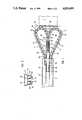
- FIG. 1is a partly broken-open illustration of part of one embodiment with the housing removed
- FIG. 2is an end view of a strip of structural section that constitutes a guide
- FIG. 3is a partly broken-open illustration of part of another embodiment with the housing removed.
- the first embodiment of the gearhas a motor 1 with a worm 4 in one piece with and extending out from its shaft in the form of a driveshaft 11.
- Worm 4longitudinally engages a motion-transmission component 5 that can travel back and forth in a guide 6 that parallels the shaft.
- the length of motion-transmission component 5can be varied by uniting or separating two strings 7 and 8 along a strip of teeth 9. Teeth 9 extend transversely across the strings and are longitudinally interrupted by a worm-engagement thread 10, leaving the teeth distributed along each side of its edge.
- teeth 9 and worm-engagement thread 10are constructed on the edges of the strings that face each other, when the strings are united the teeth will engage each other and a worm-engagement thread 10 will come into existence half on each side of the combined sides of strings 7 and 8. This situation is illustrated in section in FIG. 2 of German Patent No. 3 419 477.
- Both strings 7 and 8are secured outside guide 6 by means of two deflectors 19 and 20, which help guide the strings, subsequent to their separation and transverse displacement, into storage chambers 43 in guide 6 parallel to motion-transmission component.
- the ends of strings 7 and 8 that face away from motor 1extend at the point where they are united into an intermediary component 30 that is common to both strings, that accordingly represents the beginning of motion-transmission component 5 as it comes into existence, that engages a positioning chamber 42 in guide 6, and that can slide back and forth.
- the section of intermediary component 30 consecutive to the ends of strings 7 and 8is provided with a space 31 in the shape of a hollow cylinder that extends along the direction of travel, with its inner surface 32 having a longer diameter than that of the mechanism that drives worm 4.
- space 31is longer axially than worm 4 in the same direction, the worm can rotate freely inside it, meaning that it does not engage the worm-engagement thread 10 on strings 7 and 8.
- the engagement between worm 4 and strings 7 and 8is disestablished inside space 31, which constitutes the vicinity 33 of the disengagement.
- Intermediary component 30is in the form for instance of a plastic rectangle and has a tubular component 34 that extends from strings 7 and 8 to constitute the vicinity 33 of disengagement.
- the inner surface 32 of tubular component 34is the wall of space 31.
- Tubular component 34is in an unillustrated way fastened to or in one piece with the walls that extend out from guide 6. Only two such walls are basically necessary. Their faces constitute the remaining surfaces that help establish contact against a positioning partition 45 in positioning chamber 42.
- an operation-termination section 36 on intermediary component 30extends from tubular component 34 and is provided with a connector section 35, to which an unillustrated slide that can slide back and forth along guide 6 is secured. The slide is in turn connected to the component that is to be shifted, articulated to the panel of a door for example.
- the stretch of connecting section of driveshaft 11 facing the rotor of motor 1is provided with a conical shaft section 37 that expands coaxially and conically, and preferably with a surface that curves in toward the axis of the shaft, from the worm end or takeoff end of driveshaft 11 to motor 1.
- Shaft section 37extends at that point, either with or without shoulders, into the rotor shaft of motor 1.
- One of the bearing points of the shaftis in a base 38 and in a convexity 39 provided therein.
- Channels 40are provided in base 38 along the path of transmission between on the one hand the vicinity of unification at the level of driveshaft 11 and on the other the storage chambers 43 for the separated strings 7 and 8, along mutually symmetrical curves, that is--extending from the conically expanded end of shaft section 37, through curved wall structures on the face and, toward storage chambers 43, through straight sections into a terminal section, where they are bent down to create the outside walls of channels 40, whereas the inside walls are created by deflectors 19 and 20.
- one channel 40is created in base 38 for each section 7 and 8, resulting in one deflector 19 and 20 at the inside of the curve in each channel, whereas the opposite channel walls consist of the outside sections of the base.
- strings in the illustrated embodimentconsist of a number of consecutive strip sections 14 distributed along the direction of the string, articulated to one another, and with the teeth and the halves of worm-engagement thread 10 provided on them.
- strings 7 and 8can also be designed like the other embodiments disclosed therein or even otherwise, in the form of a toothed belt for example.
- FIG. 2illustrates a cross-section or face-on view of a structural-section rail 41 that constitutes guide 6.
- an upper communicating chamber 44that can accommodate the components that secure rail 41 to base 38 or consecutive sections of rail to one another longitudinally.
- positioning chamber 42At the longitudinal midsection of rail 41 and below communicating chamber 44 is positioning chamber 42, which accommodates both intermediary component 30 and the consecutive motion-transmission component 5 that is created out of the united strings 7 and 8 as they enter guide 6.
- Positioning chamber 42communicates through a longitudinal slot 12 in its bottom surface with a slide-positioning space 46 in which an unillustrated slide that is connected to intermediary component 30 slides back and forth.
- the positioning partition 45 inside positioning chamber 42is interrupted only by slot 12.
- Storage chambers 43are positioned below communicating chamber 44 and on each side of positioning chamber 42. The cross-section of storage chambers 43 is completely enclosed.
- FIG. 1represents the displacement of intermediary component 30 and hence of strings 7 and 8 during which engagement 4 and 10 is disestablished by the presence of worm 4 in the disengagement vicinity 33 of intermediary component 30 or of its space 31.
- the gearhas preferably been delivered on site already assembled.
- the engagement between the thread on worm 4 and the worm-engagement thread 10 on strings 7 and 8can easily be established by intervening in the slot outside of the unillustrated slide and accessible from below and accordingly, without having to remove the unillustrated housing of base 38, attaining access to intermediary component 30 from outside and sliding it away from motor 1.
- FIG. 1represents the stage of displacement attained when the mechanism has advanced too far, beyond the limit switch, establishing automatic uncoupling between motor 1 and motion-transmission component 5, as intentionally adjusted when the assembled gear is delivered.
- the second embodiment of the gearillustrated in FIG. 3, operates with a motor 1, a worm 4, a motion-transmission component 5, a guide 6, and two strings 7 and 8 that are united therein, with teeth 9 located in the sides of the strings that face each other when the strings are united and with a worm-engagement thread 10 created between them as previously described herein in relation to the previous embodiment.
- Both strings 7 and 8are secured outside guide 6 by two deflectors 19 and 20 which help guide the strings, subsequent to their separation and transverse displacement, into storage drums 50 positioned on each side of where they are united, the vicinity of worm 4 and upstream, that is.
- Channels 40are provided in the base along the path of transmission between on the one hand the vicinity of unification at the level of driveshaft 11 and on the other the storage drums 50 for the separated strings 7 and 8, along mutually symmetrical curves, that is--extending from the conically expanded end of shaft section 37 and through curved wall structures on the face into the space above floors 51 into storage drums 50.
- Each floor 51is a circular disk with a rotating mount 56 of any desired design in the center.
- the floors 51 of storage drums 50extend in a common plane that is approximately horizontal when the gear is installed on site, with the axes of rotation accordingly extending more or less vertically.
- the surfaces of floors 51 that face the observerare in the form of contact surfaces 52, which the longitudinal sections of strings 7 and 8 that have been transferred into the drums rest against.
- each floor 51is subject to the force of a spring 53, specifically in such a way that the spring will tend to move the floor in the direction in which the particular string is being accommodated in a storage drum 50 around the axis of rotation.
- the resultis that strings 7 and 8 will be forced to slide along the inside guide wall of the particular channel 40 even during the storage motion.
- the outside walls of channels 40 and conical shaft section 37primarily represent preventive measures and only accommodate and guide the strings when they, due to interference with the rotational storage process or due to a broken spring, must be advanced into their stored position.
- the particular spring 53 associated with each floor 51is positioned on the bottom surface of the floor, the surface facing contact surface 52 and hence away from the viewer, and is represented by the broken lines in the drawing in the form of a spiral spring that, as illustrated, preferably extends along a radially outward area and is long enough to generate a flat force-to-path characteristic along the unwinding-rotation area of the floor, so that only a slight spring force is exerted on the particular floor and the tension on the strings and hence the force with which they are driven against the guide surfaces remain low.
- spiral springswhich are preferably strips of leaf spring, can be secured with the inner end of the spiral against base 38 and the outer end against the floor or vice versa.
- Guide 6is preferably in the form of a rail made out of structural section with a positioning chamber 42 that has an unillustrated longitudinal slot along its bottom surface, through which the connector section 35 of intermediary component 30 communicates in an unillustrated way with the slide or directly with the component that is to be moved, particularly the panel of a door, the panel of a garage overhead moving door for example.
Landscapes
- Engineering & Computer Science (AREA)
- General Engineering & Computer Science (AREA)
- Mechanical Engineering (AREA)
- Life Sciences & Earth Sciences (AREA)
- Geology (AREA)
- Structural Engineering (AREA)
- Transmission Devices (AREA)
- Forging (AREA)
- Ultra Sonic Daignosis Equipment (AREA)
- Power-Operated Mechanisms For Wings (AREA)
- Milling Processes (AREA)
- Operating, Guiding And Securing Of Roll- Type Closing Members (AREA)
Abstract
Description
A gear of this type is known from German Patent No. 3 419 477, and reference will be expressly made herein to the embodiments specified in that document, without, however, limiting the present scope to them.
The special characteristic of the gear is that the strings, when linked together inside the guide, can transmit considerable tensile and compressive forces without generating much friction against the walls of the guide. Inside the guide the two strings are combined into a single intermediary component, to which the component that is to be shifted, the panel of a door for instance and especially the panel of a garage overhead door or similar structure, is connected.
The main concept behind these gears, which usually have continuous motion-transmission components, chains for example, although they may also involve discontinuous components as in the aforesaid patent, is that the engagement between the rotary drive mechanism and the motion-transmission component is disestablished at no point along the path of motion. Limiting switches are appropriately positioned to determine the back-and-forth motion along its intended path. The edges of the door panel are provided with a safety measure in the form of sensor strips that, when anything gets caught in the panel's path, terminate or reverse its motion. It is desirable to be able to deliver a gear of this type as completely assembled as possible to where it will be used to shorten and simplify the job of installing it on site as much as possible, eliminating in particular the necessity of intervention into the mechanism itself. In particular, if the rotary drive mechanism is engaged with the motion-transmission component when the gear is completely assembled, careless activation of the motor, in the wrong direction for example etc., can lead not only to injury but also to destruction of the parts involved.
Furthermore, many emergency means of preventing the mechanism from exceeding one of its limiting positions have been considered in order to avoid damage to the gear. Thus, an extra limit switch has been provided farther along the path of motion, demanding more expense and an according extension of the path. It is also possible to provide an overload switch that executes a mechanical motion against the force of a spring, whereby the resistance to displacement offered by the spring must be higher than the stress on the gear during normal operation. The electric motor can also be protected from overload by monitoring the electric parameters. In the last two cases, however, it is impossible to prevent the mechanical load exerted on the gear in such a situation from being much higher than in normal operation. This means that the components subjected to stress must be very hefty to eliminate the risk of their being destroyed.
The space required for feeding and introducing the separated strings is an especially important factor in allowing the gear to be delivered as completely assembled as possible even when the demand for space during shipment means that it must be dismantled at least into a drive component and a guide component. The aforementioned patent accordingly discloses not only feeding the strings parallel to the guide but also accommodating each separate string in a drum-type storage unit on each side of the point at which they unite.
In addition to the desirability of minimalizing the friction of the motion-transmission component inside the guide to the greatest extent possible, how easily and with how little friction each separated string can be moved in or out of its stored position is also significant, to keep the power consumption and requisite output of the motor low.
The object of the present invention is to make available a gear of the aforesaid type that can be delivered as completely assembled as possible and installed on site with no risk of damage due to overloading the mechanism when the motor is turned on for the first time or when at least one of the terminating positions is exceeded during operation.
With a gear having the characteristics recited in the preamble to claim 1 as a point of departure, this object is attained in accordance with the invention by the characteristics recited in the body of that claim.
Although the intermediary component that disestablishes the engagement between the rotary drive and the motion-transmission component in accordance with the invention can be a specific section of the engaged strings, it is in a preferred embodiment one that is designed for both strings together and one that the end of each discontinuous string, the end toward the rotary drive, is secured to. The simplest way of disestablishing the engagement is by means of a drive mechanism positioned without any teeth at the intermediary component and engaged in an idling relationship by the takeoff component of the rotary drive when the intermediary component is in an appropriate delivery-assembly or emergency-displacement position.
The point of departure for normal operation in this case as well is basically the concept of constant operational engagement, and the overall drive mechanism is contrlled with limit switches of conventional design. If the limit switch located at the end of the path of motion toward the rotary drive mechanism fails, the motion-transmission component and hence the intermediary component will travel beyond that terminating position until the drive component of the rotary drive mechanism arrives in the vicinity of the disengagement and automatically disengages the rotary drive mechanism from the motion-transmission component. Considering now the other terminating position of the motion-transmission component, and assuming incorrect travel beyond the limit switch at that point, an excess travel that must be slight maintained can also be provided there, within which the engagement between the rotary drive mechanism and in this case the other end of the motion-transmission component is disestablished, the simplest procedure being to displace the ends of the string that face the intermediary component out over the section where the drive component of the rotary drive mechanism is engaged. With doors, furthermore, it is also possible to activate a safety strip when the closure section has been exceeded, and hence trigger emergency shutoff.
In one especially preferred embodiment of the invention the engagement between the rotary drive mechanism and the motion-transmission component is in the form of a worm that engages a matching worm-engagement thread. The result is an engagement between the thread on the worm, which is part of the rotary drive mechanism, and the worm-engagement thread, which in itself continuously spirals around within the motion-transmission component. Thus, the actual worm-engagement thread does not come into existence until the two strings are united. To make it possible to design the strings as identical as possible, to make them mutually symmetrical that is, each half of the worm-engagement thread in one especially preferred embodiment is provided in one of the sides of the strings, which face each other or engage each other with their teeth when the two strings are united, in such a way that the worm-engagement thread can be considered separated along an axial midplane. The intermediary component has in a practical way a hollow cylindrical space that parallels the direction of travel in the vicinity of the disengagement. The inside dimension of the space is slightly longer than the radial extent of the thread on the worm, which can accordingly rotate freely therein. The design also protect the worm and facilitates reengagement of the worm thread and worm-engagement thread by an appropriate axial displacement.
The position of the motion-transmission component is established in such a way when the gear is assembled that the worm on the rotary drive mechanism or its takeoff component will be very generally located in the vicinity of the disengagement and will accordingly be able to rotate freely within it in relation to the gearing structure on the motion-transmission component. When the gear is installed on site in this state, switching the overall mechanism on carelessly or unintentionally will lead only to free rotation of the rotary drive mechanism, with the motion-transmission component remaining unaffected. At this stage the correct direction of rotation of the rotary drive mechanism is established or initiated and engagement established by appropriately displacing the motion-transmission component away from the rotary drive mechanism.
While one especially preferred embodiment is in the stage of being assembled as completely as possible, a storage-drum unit that is in itself known is mounted on each side of the section where the strings are separated in such a way that both storage drums are provided with a rotary bearing, at least on their floor, on which the stored string is laid down in a spiral.
Making the floor of each storage drum rotating avoids the frictional resistance that occurs in relation to storage in chambers that parallel the guide. If a rotary bearing is considered satisfactory and if the rotation is introduced by applying force against the strings inside the storage unit, it will be preferable to construct a wall along the edge of and projecting above the floor for the sections of string to rest against once they have been introduced. Depending on how much space the storage drums take up when installed, it can also be practical for a terminal section of the wall facing the contact surface to rotate along with the floor.
If the floor of the storage drums is rotated by inserting the string, an outside channeling surface must be provided between the point at which the strings are united and the wall of the drum in order to allow the advance of the string to be as smooth as possible. A conical shaft section is provided especially for this purpose at one end, the end facing the rotor, of the shaft between the motor rotor and the drive worm. The narrow section of the cone is in the vicinity of the worm, and the wide section of the cone is toward the rotor, resulting in a surface that curves toward the axis of the shaft and expands, with a stationary channeling wall in the base aligning with the accordingly expanded shoulder. If the strings are united while being extracted from the storage drums, they will be subjected to tension, causing the strings to rest in channel-shaped recesses against the inside surface of an opposing channeling wall that is also constructed on the base.
The floor in one especially preferred embodiment of the invention is subjected to the force of a spring along the direction of rotation in which the string is coiled within that storage drum and is accordingly increasingly advanced into its stored position. Thus, not only will the strings slide along the channeling sides associated with them as they are extracted out of storage and united into an increasingly longer motion-transmission component, but the same process will be repeated as the strings separate and the motion-transmission component becomes shorter while they are being returned to their particular storage position. Thus the heavy weight of the low-friction channeling structure can be confined to the inside surface of the channeling walls.
The particular spring involved in each process is preferably located on the floor opposite the contact surface. This spring is preferably a helical spring, especially a strip of leaf spring. The spring will preferably be long, extending into the radially outer area of the floor, resulting in a flat characteristic over its total range and keeping the force needed to stress the spring uniformly low, so that the strings extracted from storage to tension the spring will be subject to a slight stress.
Both storage drums in one preferred embodiment are positioned on both sides of the point at which the strings are united--one drum, that is, on each of the two sides--in such a way that their floors are in the same plane, a plane that is more or less in the horizontal position when the equipment is installed. This system saves space and makes it possible to install the base with the motor and already mounted strings and intermediary component separate from the one-part or multiple-part guide rails, dividing up the space in a way that is very practical from the aspect of shipping requirements.
Preferred embodiments of the invention will be evident from the subsidiary claims in conjunction with the examples illustrated in the drawings.
FIG. 1 is a partly broken-open illustration of part of one embodiment with the housing removed,
FIG. 2 is an end view of a strip of structural section that constitutes a guide, and
FIG. 3 is a partly broken-open illustration of part of another embodiment with the housing removed.
The first embodiment of the gear has amotor 1 with a worm 4 in one piece with and extending out from its shaft in the form of a driveshaft 11. Worm 4 longitudinally engages a motion-transmission component 5 that can travel back and forth in aguide 6 that parallels the shaft. The length of motion-transmission component 5 can be varied by uniting or separating twostrings teeth 9. Teeth 9 extend transversely across the strings and are longitudinally interrupted by a worm-engagement thread 10, leaving the teeth distributed along each side of its edge. Sinceteeth 9 and worm-engagement thread 10 are constructed on the edges of the strings that face each other, when the strings are united the teeth will engage each other and a worm-engagement thread 10 will come into existence half on each side of the combined sides ofstrings
Bothstrings outside guide 6 by means of twodeflectors storage chambers 43 inguide 6 parallel to motion-transmission component. The ends ofstrings motor 1 extend at the point where they are united into anintermediary component 30 that is common to both strings, that accordingly represents the beginning of motion-transmission component 5 as it comes into existence, that engages apositioning chamber 42 inguide 6, and that can slide back and forth. The section ofintermediary component 30 consecutive to the ends ofstrings space 31 in the shape of a hollow cylinder that extends along the direction of travel, with itsinner surface 32 having a longer diameter than that of the mechanism that drives worm 4. Sincespace 31, furthermore, is longer axially than worm 4 in the same direction, the worm can rotate freely inside it, meaning that it does not engage the worm-engagement thread 10 onstrings strings space 31, which constitutes thevicinity 33 of the disengagement.
The engagement between the sections is established and disestablished at the section of driveshaft 11 between worm 4 and the rotor ofmotor 1. To ensure satisfactory positioning ofstrings storage chambers 43 inguide 6, the stretch of connecting section of driveshaft 11 facing the rotor ofmotor 1 is provided with aconical shaft section 37 that expands coaxially and conically, and preferably with a surface that curves in toward the axis of the shaft, from the worm end or takeoff end of driveshaft 11 tomotor 1.Shaft section 37 extends at that point, either with or without shoulders, into the rotor shaft ofmotor 1. One of the bearing points of the shaft is in abase 38 and in aconvexity 39 provided therein.
The strings in the illustrated embodiment consist of a number ofconsecutive strip sections 14 distributed along the direction of the string, articulated to one another, and with the teeth and the halves of worm-engagement thread 10 provided on them. Although this design corresponds to that of the embodiment illustrated in FIG. 3 of German Patent No. 3 419 477,strings
FIG. 2 illustrates a cross-section or face-on view of a structural-section rail 41 that constitutesguide 6. Between the walls ofrail 41 is an upper communicating chamber 44 that can accommodate the components that securerail 41 tobase 38 or consecutive sections of rail to one another longitudinally. At the longitudinal midsection ofrail 41 and below communicating chamber 44 is positioningchamber 42, which accommodates bothintermediary component 30 and the consecutive motion-transmission component 5 that is created out of theunited strings guide 6. Positioningchamber 42 communicates through alongitudinal slot 12 in its bottom surface with a slide-positioning space 46 in which an unillustrated slide that is connected tointermediary component 30 slides back and forth. Thus, thepositioning partition 45 inside positioningchamber 42 is interrupted only byslot 12.Storage chambers 43 are positioned below communicating chamber 44 and on each side of positioningchamber 42. The cross-section ofstorage chambers 43 is completely enclosed.
FIG. 1 represents the displacement ofintermediary component 30 and hence ofstrings engagement 4 and 10 is disestablished by the presence of worm 4 in thedisengagement vicinity 33 ofintermediary component 30 or of itsspace 31. At this stage of displacement the gear has preferably been delivered on site already assembled. The engagement between the thread on worm 4 and the worm-engagement thread 10 onstrings base 38, attaining access tointermediary component 30 from outside and sliding it away frommotor 1. With the motor rotor turning in the correct direction, then, the thread on worm 4 will rotate into the worm-engagement thread 10 onstrings united strings intermediary component 30. With worm 4 rotating in the opposite direction, the motion-transmission component created out of theunited strings intermediary component 30 will be continuously extracted fromguide 6 and towardmotor 1, withstrings conical shaft section 37 and the subsequent outer walls ofchannels 40. A limit switch is employed to ensure that during properly functioning operation the engagement between worm 4 and theunited strings intermediary component 30 still inserted inguide 6 as illustrated in FIG. 1. Thus, FIG. 1 represents the stage of displacement attained when the mechanism has advanced too far, beyond the limit switch, establishing automatic uncoupling betweenmotor 1 and motion-transmission component 5, as intentionally adjusted when the assembled gear is delivered.
The second embodiment of the gear, illustrated in FIG. 3, operates with amotor 1, a worm 4, a motion-transmission component 5, aguide 6, and twostrings teeth 9 located in the sides of the strings that face each other when the strings are united and with a worm-engagement thread 10 created between them as previously described herein in relation to the previous embodiment.
Bothstrings outside guide 6 by twodeflectors storage drums 50 positioned on each side of where they are united, the vicinity of worm 4 and upstream, that is.Channels 40 are provided in the base along the path of transmission between on the one hand the vicinity of unification at the level of driveshaft 11 and on the other the storage drums 50 for the separatedstrings shaft section 37 and through curved wall structures on the face into the space abovefloors 51 into storage drums 50.
Eachfloor 51 is a circular disk with arotating mount 56 of any desired design in the center. Thefloors 51 ofstorage drums 50 extend in a common plane that is approximately horizontal when the gear is installed on site, with the axes of rotation accordingly extending more or less vertically. The surfaces offloors 51 that face the observer are in the form of contact surfaces 52, which the longitudinal sections ofstrings string 7 has arrived at the associated floor, it will be supplied to it along the direction of rotation almost without motion. If the rotation offloor 51, which will then preferably be provided with an edge that extends laterally up beyond the periphery ofcontact surface 52, is initiated by the advance of the string being introduced into its stored position, the advancing strings will slide along the particular outside wall of the channels, which is why driveshaft 11 is provided with aconical section 37. When the strings are extracted out of storage in the other direction on the other hand, they will rest subject to tension against the inner guide walls of theparticular channel 40.
The drawing illustrates an embodiment in which eachfloor 51 is subject to the force of aspring 53, specifically in such a way that the spring will tend to move the floor in the direction in which the particular string is being accommodated in astorage drum 50 around the axis of rotation. The result is thatstrings particular channel 40 even during the storage motion. Thus, there will always be a slight tension onstrings channels 40 andconical shaft section 37 primarily represent preventive measures and only accommodate and guide the strings when they, due to interference with the rotational storage process or due to a broken spring, must be advanced into their stored position.
Theparticular spring 53 associated with eachfloor 51 is positioned on the bottom surface of the floor, the surface facingcontact surface 52 and hence away from the viewer, and is represented by the broken lines in the drawing in the form of a spiral spring that, as illustrated, preferably extends along a radially outward area and is long enough to generate a flat force-to-path characteristic along the unwinding-rotation area of the floor, so that only a slight spring force is exerted on the particular floor and the tension on the strings and hence the force with which they are driven against the guide surfaces remain low.
It will obviously be unnecessary in this case to provide therotating floors 51 with an edge to accommodate the sections. The spiral springs, which are preferably strips of leaf spring, can be secured with the inner end of the spiral againstbase 38 and the outer end against the floor or vice versa.
Claims (19)
1. An arrangement for converting rotary motion into translational motion, comprising: driving motor means; rotary drive means connected to said motor means; motion-transmission means moveable translationally and divided longitudinally along a direction of motion into tow strings; guide means for guiding said strings transversely, said strings being positioned outside said guide means at one end and separated from each other, said strings being united at the other end inside said guide means, said guide means preventing the united end of the strings from being laterally removable from each other; engagement means for connecting said strings to said rotary drive means where they are united, said strings having teeth on sides facing each other in vicinity of said guide means, said strings engaging each other by said teeth; an intermediate component in said guide means remote from said rotary drive means, said strings having ends secured to said intermediate component, said intermediate component being common to both strings; said strings being disengaged from said engagement means in vicinity of said intermediate component; a worm extending along said guide means and engaging a worm-engagement thread on facing sides of said strings in vicinity of said guide means and adjacent to a section of said strings carrying said teeth, said worm connecting said strings to said rotary drive means at a location where said strings are united, said teeth extending substantially perpendicular to a longitudinal axis of said guide means, said worm-engagement thread being divided into two halves by an axial midplane, said strings being connected to said intermediate component.
2. An arrangement as defined in claim 1, wherein said guide means has a slot therein and along said guide means, said intermediate component having a connector section oriented toward said slot.
3. An arrangement as defined in claim 2, wherein said connector section comprises a bore positioned in a terminating section of said intermediate component.
4. An arrangement as defined in claim 1, including a storage drum for each string adjacent to a point of separation of said strings for storing said strings separated outside said guide means, said storage drum having at least a rotating base for depositing stored string in a spiral on said base.
5. An arrangement as defined in claim 4, including spring means tensioning said base along a direction of winding of said string, said spring means being mounted on a bottom surface of said base.
6. An arrangement as defined in claim 4, wherein said string has an end opening into said storage drum and being secured to said base.
7. An arrangement as defined in claim 4, wherein rotating bases of said storage drums on each side of the united section of said strings extend in a horizontal common plane when said arrangement is in an operational state.
8. An arrangement as defined in claim 5, wherein said spring means spirals along a bottom surface of said base.
9. An arrangement as defined in claim 8, wherein said spring means comprises a flat strip member.
10. An arrangement as defined in claim 8, wherein said spring means has a spirally outward end secured to said base, said spring means having a spirally inward end secured to a base-shaped supporting member.
11. An arrangement as defined in claim 1, including a storage drum for each of said strings adjacent to the location of separation of said strings, said strings being separated outside said guide means, each storage drum having at least a rotating base for depositing stored string in a spiral on the base; spring means tensioning said base along a direction corresponding to the winding of said string, said spring means being mounted on a bottom surface of said base.
12. An arrangement for converting rotary motion into translational motion, comprising: driving motor means; rotary drive means connected to said motor means; motion-transmission means moveable translationally and divided logitudinally along a direction of motion into two strings; guide means for guiding said strings transversely, said strings being positioned outside said guide means at one end and separated from each other, said strings being united at the other end inside said guide means, said guide means preventing the united end of the strings from being laterally removable from each other; engagement means for connecting said strings to said rotary drive means where they are united, said strings having teeth on sides facing each other in vicinity of said guide means, said strings engaging each other by said teeth; an intermediate component in said guide means remote from said rotary drive means, said strings having ends secured to said intermediate component, said intermediate component being common to both strings; said strings being disengaged from said engagement means in vicinity of said intermediate component; a worm extending along said guide means and engaging a worm-engagement thread on facing sides of said strings in vicinity of said guide means and adjacent to a section of said strings carrying said teeth, said worm connecting said strings to said rotary drive means at a location where said strings are united, said teeth extending substantially perpendicular to a longitudinal axis of said guide means, said worm-engagement thread being divided into two halves by an axial midplane, said strings being connected to said intermediate component, said intermediate component having a hollow space inside said component and extending along said guide means, said hollow space being axially longer than the thread on said worm.
13. An arrangement as defined in claim 12, wherein said hollow space extends coaxial with worm-engagement thread on said strings, said hollow space extending also coaxial with said worm, said hollow space surrounding with play a radially outer demarcation of the thread on said worm in vicinity of disengagement of said strings from said engagement means.
14. An arrangement as defined in claim 13, wherein said intermediate component remains within said guide means at every stage of displacement of said motion-transmission means, said intermediate component having walls along said guide means; and a tubular member surrounding said worm.
15. An arrangement as defined in claim 12, including a shaft between said motor means and said worm and having a conical shaft section between said motor means and said worm, said conical section having a surface curving along an axis of a cone, said cone having a surface functioning as a guide for said strings as said strings separate.
16. An arrangement as defined in claim 15, wherein said guide comprises a multi-chambered hollow structural-section rail.
17. An arrangement as defined in claim 16, wherein said intermediate component is accommodated in a positioning chamber, said positioning chamber having two storage chambers on sides of said positioning chamber for each of said strings when separated.
18. An arrangement as defined in claim 17, wherein said driving motor means has components in a communicating chamber above said positioning chamber.
19. An arrangement for converting rotary motion into translational motion, comprising: driving motor means; rotary drive means connected to said motor means; motion-transmission means moveable translationally and divided longitudinally along a direction of motion into two strings; guide means for guiding said strings transversely, said strings being positioned outside said guide means at one end separated from each other, said strings being united at the other end inside said guide means, said guide means preventing the united end of the strings from being laterally removable from each other; engagement means for connecting said strings to said rotary drive means where they are united, said strings having teeth on sides facing each other in vicinity of said guide means, said strings engaging each other by said teeth; an intermediate component in said guide means remote from said rotary drive means, said strings having ends secured to said intermediate component, said intermediate component being common to both strings; said strings being disengaged from said engagement means in vicinity of said intermediate component; a worm extending along said guide means and engaging a worm-engagement thread on facing sides of said strings in vicinity of said guide means and adjacent to a section of said strings carrying said teeth, said worm connecting said strings to said rotary drive means at a location where said strings are united, said teeth extending substantially perpendicular to a longitudinal axis of said guide means, said worm-engagement thread being divided into two halves by an axial midplane, said strings being connected to said intermediate component, said intermediate component having a hollow space inside said component and extending along said guide means, said hollow space being axially longer than the thread of said worm; said intermediate component having a cylindrical hollow space extending coaxial with a worm-engagement thread on said strings and extending also coaxial with said worm, said cylindrical hollow space surrounding with play radially an outer demarcation of the thread on said worm in vicinity of disengagement of said strings from said engagement means; said intermediate component remaining inside said guide means at every stage of displacement of said motion-transmission means, said intermediate component having walls along said guide means; and a tubular member secured against said walls; said guide means having a slot therein and along said guide means, said intermediate component having a connector section oriented toward said slot.
Applications Claiming Priority (4)
| Application Number | Priority Date | Filing Date | Title |
|---|---|---|---|
| DE19863603122DE3603122A1 (en) | 1986-02-01 | 1986-02-01 | Mechanism for converting a rotary motion into a translational motion |
| DE19863603121DE3603121A1 (en) | 1986-02-01 | 1986-02-01 | DEVICE FOR CONVERTING A ROTATORY STRETCHABLE TO A TRANSLATORY MOVEMENT BY MEANS OF TWO STORAGE DRUMS |
| DE3603121 | 1986-02-01 | ||
| DE3603122 | 1986-02-01 |
Publications (1)
| Publication Number | Publication Date |
|---|---|
| US4819495Atrue US4819495A (en) | 1989-04-11 |
Family
ID=25840620
Family Applications (1)
| Application Number | Title | Priority Date | Filing Date |
|---|---|---|---|
| US07/008,935Expired - LifetimeUS4819495A (en) | 1986-02-01 | 1987-01-30 | Gear for converting a rotary into a translational motion |
Country Status (6)
| Country | Link |
|---|---|
| US (1) | US4819495A (en) |
| EP (1) | EP0232803B1 (en) |
| AT (1) | ATE43882T1 (en) |
| DE (2) | DE3603121A1 (en) |
| ES (1) | ES2009744B3 (en) |
| GR (1) | GR3000144T3 (en) |
Cited By (184)
| Publication number | Priority date | Publication date | Assignee | Title |
|---|---|---|---|---|
| US5241873A (en)* | 1990-06-06 | 1993-09-07 | Steuerungstechnik GmbH Hormann KG Antriebs- und & Co. Produktions | Transmission that converts a rotary into a translational motion |
| US5271182A (en)* | 1991-09-24 | 1993-12-21 | Aug.Winkhaus Gmbh & Co. Kg | Device for opening and closing the panel of a window, door, ventilation hatch, or similar closure |
| EP0777028A1 (en)* | 1995-12-01 | 1997-06-04 | V. Kann Rasmussen Industri A/S | An operator with at least two linkage mechanisms for opening and closing pivotal windows |
| US6530177B1 (en)* | 1999-03-31 | 2003-03-11 | Vkr Holding A/S | Double-chain window or door operator |
| US20040003543A1 (en)* | 2002-06-25 | 2004-01-08 | Sumitomo Wiring Systems, Ltd. | Cable guide and power supply apparatus for a vehicle slide door |
| US20040020612A1 (en)* | 2002-04-17 | 2004-02-05 | Giuseppe Bosio | Ceiling actuator for up-and-over and sectional doors |
| US7082722B1 (en)* | 1998-04-08 | 2006-08-01 | Vkr Holding A/S | Method and apparatus for making an elongate spindle member of chain links for transfer of pressure and tensile loads |
| US20080200294A1 (en)* | 2007-02-20 | 2008-08-21 | Jon Scott | Double chain linear actuator |
| US20090211220A1 (en)* | 2008-02-27 | 2009-08-27 | Jon Scott | Link for a linear actuator |
| US20100077810A1 (en)* | 2007-02-01 | 2010-04-01 | Daniele De Franceschi | Multifunctional locking device and servomotor with actuator which can be up wound up around an interchangeable reel |
| US20110047700A1 (en)* | 2009-08-25 | 2011-03-03 | Tobias Klemm | Longitudinal Drive for Patient Support Systems |
| US20120261629A1 (en)* | 2011-04-18 | 2012-10-18 | Eric Andkjar | Vertical lift mechanism for use in confined spaces |
| US20150343648A1 (en)* | 2010-05-31 | 2015-12-03 | National Institute Of Advanced Industrial Science And Technology | Direct acting extensible and retractable arm mechanism, and robot arm provided with direct acting extensible and retractable arm mechanism |
| US20180372195A1 (en)* | 2016-02-29 | 2018-12-27 | Life Robotics Inc. | Linear extension and retraction mechanism and robot arm mechanism |
| CN113459127A (en)* | 2021-07-31 | 2021-10-01 | 西南科技大学 | Self-growing soft and hard integrated robot and application thereof |
| JP2021173391A (en)* | 2020-04-30 | 2021-11-01 | トヨタ自動車株式会社 | Expansion/contraction mechanism and movable body |
| US20220031322A1 (en)* | 2020-07-28 | 2022-02-03 | Cilag Gmbh International | Surgical instruments with firing member closure features |
| US20220205515A1 (en)* | 2019-04-10 | 2022-06-30 | Serapid France | Rigid multilinear actuator with flexible strand |
| US11599091B2 (en)* | 2019-12-06 | 2023-03-07 | Hello Robot | Telescopic structure actuation |
| US11648005B2 (en) | 2008-09-23 | 2023-05-16 | Cilag Gmbh International | Robotically-controlled motorized surgical instrument with an end effector |
| US11648006B2 (en) | 2007-06-04 | 2023-05-16 | Cilag Gmbh International | Robotically-controlled shaft based rotary drive systems for surgical instruments |
| US11653915B2 (en) | 2020-12-02 | 2023-05-23 | Cilag Gmbh International | Surgical instruments with sled location detection and adjustment features |
| US11660110B2 (en) | 2006-01-31 | 2023-05-30 | Cilag Gmbh International | Motor-driven surgical cutting and fastening instrument with tactile position feedback |
| US11684361B2 (en) | 2008-09-23 | 2023-06-27 | Cilag Gmbh International | Motor-driven surgical cutting instrument |
| US11684434B2 (en) | 2019-06-28 | 2023-06-27 | Cilag Gmbh International | Surgical RFID assemblies for instrument operational setting control |
| US11696761B2 (en) | 2019-03-25 | 2023-07-11 | Cilag Gmbh International | Firing drive arrangements for surgical systems |
| US11696757B2 (en) | 2021-02-26 | 2023-07-11 | Cilag Gmbh International | Monitoring of internal systems to detect and track cartridge motion status |
| US11696759B2 (en) | 2017-06-28 | 2023-07-11 | Cilag Gmbh International | Surgical stapling instruments comprising shortened staple cartridge noses |
| US11701111B2 (en) | 2019-12-19 | 2023-07-18 | Cilag Gmbh International | Method for operating a surgical stapling instrument |
| US11701110B2 (en) | 2013-08-23 | 2023-07-18 | Cilag Gmbh International | Surgical instrument including a drive assembly movable in a non-motorized mode of operation |
| US11701113B2 (en) | 2021-02-26 | 2023-07-18 | Cilag Gmbh International | Stapling instrument comprising a separate power antenna and a data transfer antenna |
| US11701115B2 (en) | 2016-12-21 | 2023-07-18 | Cilag Gmbh International | Methods of stapling tissue |
| US11707273B2 (en) | 2012-06-15 | 2023-07-25 | Cilag Gmbh International | Articulatable surgical instrument comprising a firing drive |
| US11712244B2 (en) | 2015-09-30 | 2023-08-01 | Cilag Gmbh International | Implantable layer with spacer fibers |
| US11717294B2 (en) | 2014-04-16 | 2023-08-08 | Cilag Gmbh International | End effector arrangements comprising indicators |
| US11717291B2 (en) | 2021-03-22 | 2023-08-08 | Cilag Gmbh International | Staple cartridge comprising staples configured to apply different tissue compression |
| US11717297B2 (en) | 2014-09-05 | 2023-08-08 | Cilag Gmbh International | Smart cartridge wake up operation and data retention |
| US11723657B2 (en) | 2021-02-26 | 2023-08-15 | Cilag Gmbh International | Adjustable communication based on available bandwidth and power capacity |
| US11723658B2 (en) | 2021-03-22 | 2023-08-15 | Cilag Gmbh International | Staple cartridge comprising a firing lockout |
| US11723662B2 (en) | 2021-05-28 | 2023-08-15 | Cilag Gmbh International | Stapling instrument comprising an articulation control display |
| US11730473B2 (en) | 2021-02-26 | 2023-08-22 | Cilag Gmbh International | Monitoring of manufacturing life-cycle |
| US11730471B2 (en) | 2016-02-09 | 2023-08-22 | Cilag Gmbh International | Articulatable surgical instruments with single articulation link arrangements |
| US11730477B2 (en) | 2008-10-10 | 2023-08-22 | Cilag Gmbh International | Powered surgical system with manually retractable firing system |
| US11730474B2 (en) | 2005-08-31 | 2023-08-22 | Cilag Gmbh International | Fastener cartridge assembly comprising a movable cartridge and a staple driver arrangement |
| US11737754B2 (en) | 2010-09-30 | 2023-08-29 | Cilag Gmbh International | Surgical stapler with floating anvil |
| US11737751B2 (en) | 2020-12-02 | 2023-08-29 | Cilag Gmbh International | Devices and methods of managing energy dissipated within sterile barriers of surgical instrument housings |
| US11737749B2 (en) | 2021-03-22 | 2023-08-29 | Cilag Gmbh International | Surgical stapling instrument comprising a retraction system |
| US11744593B2 (en) | 2019-06-28 | 2023-09-05 | Cilag Gmbh International | Method for authenticating the compatibility of a staple cartridge with a surgical instrument |
| US11744603B2 (en) | 2021-03-24 | 2023-09-05 | Cilag Gmbh International | Multi-axis pivot joints for surgical instruments and methods for manufacturing same |
| US11744588B2 (en) | 2015-02-27 | 2023-09-05 | Cilag Gmbh International | Surgical stapling instrument including a removably attachable battery pack |
| US11744583B2 (en) | 2021-02-26 | 2023-09-05 | Cilag Gmbh International | Distal communication array to tune frequency of RF systems |
| US11744581B2 (en) | 2020-12-02 | 2023-09-05 | Cilag Gmbh International | Powered surgical instruments with multi-phase tissue treatment |
| US11749877B2 (en) | 2021-02-26 | 2023-09-05 | Cilag Gmbh International | Stapling instrument comprising a signal antenna |
| US11751867B2 (en) | 2017-12-21 | 2023-09-12 | Cilag Gmbh International | Surgical instrument comprising sequenced systems |
| US11751869B2 (en) | 2021-02-26 | 2023-09-12 | Cilag Gmbh International | Monitoring of multiple sensors over time to detect moving characteristics of tissue |
| US11759208B2 (en) | 2015-12-30 | 2023-09-19 | Cilag Gmbh International | Mechanisms for compensating for battery pack failure in powered surgical instruments |
| US11759202B2 (en) | 2021-03-22 | 2023-09-19 | Cilag Gmbh International | Staple cartridge comprising an implantable layer |
| US11771419B2 (en) | 2019-06-28 | 2023-10-03 | Cilag Gmbh International | Packaging for a replaceable component of a surgical stapling system |
| US11771426B2 (en) | 2007-01-10 | 2023-10-03 | Cilag Gmbh International | Surgical instrument with wireless communication |
| US11779330B2 (en) | 2020-10-29 | 2023-10-10 | Cilag Gmbh International | Surgical instrument comprising a jaw alignment system |
| US11779336B2 (en) | 2016-02-12 | 2023-10-10 | Cilag Gmbh International | Mechanisms for compensating for drivetrain failure in powered surgical instruments |
| US11779420B2 (en) | 2012-06-28 | 2023-10-10 | Cilag Gmbh International | Robotic surgical attachments having manually-actuated retraction assemblies |
| US11786239B2 (en) | 2021-03-24 | 2023-10-17 | Cilag Gmbh International | Surgical instrument articulation joint arrangements comprising multiple moving linkage features |
| US11786243B2 (en) | 2021-03-24 | 2023-10-17 | Cilag Gmbh International | Firing members having flexible portions for adapting to a load during a surgical firing stroke |
| US11793509B2 (en) | 2012-03-28 | 2023-10-24 | Cilag Gmbh International | Staple cartridge including an implantable layer |
| US11793514B2 (en) | 2021-02-26 | 2023-10-24 | Cilag Gmbh International | Staple cartridge comprising sensor array which may be embedded in cartridge body |
| US11793518B2 (en) | 2006-01-31 | 2023-10-24 | Cilag Gmbh International | Powered surgical instruments with firing system lockout arrangements |
| US11793513B2 (en) | 2017-06-20 | 2023-10-24 | Cilag Gmbh International | Systems and methods for controlling motor speed according to user input for a surgical instrument |
| US11793516B2 (en) | 2021-03-24 | 2023-10-24 | Cilag Gmbh International | Surgical staple cartridge comprising longitudinal support beam |
| US11793512B2 (en) | 2005-08-31 | 2023-10-24 | Cilag Gmbh International | Staple cartridges for forming staples having differing formed staple heights |
| US11801047B2 (en) | 2008-02-14 | 2023-10-31 | Cilag Gmbh International | Surgical stapling system comprising a control circuit configured to selectively monitor tissue impedance and adjust control of a motor |
| US11806013B2 (en) | 2012-06-28 | 2023-11-07 | Cilag Gmbh International | Firing system arrangements for surgical instruments |
| US11806011B2 (en) | 2021-03-22 | 2023-11-07 | Cilag Gmbh International | Stapling instrument comprising tissue compression systems |
| US11811253B2 (en) | 2016-04-18 | 2023-11-07 | Cilag Gmbh International | Surgical robotic system with fault state detection configurations based on motor current draw |
| US11812964B2 (en) | 2021-02-26 | 2023-11-14 | Cilag Gmbh International | Staple cartridge comprising a power management circuit |
| US11812965B2 (en) | 2010-09-30 | 2023-11-14 | Cilag Gmbh International | Layer of material for a surgical end effector |
| US11812954B2 (en) | 2008-09-23 | 2023-11-14 | Cilag Gmbh International | Robotically-controlled motorized surgical instrument with an end effector |
| US11812958B2 (en) | 2014-12-18 | 2023-11-14 | Cilag Gmbh International | Locking arrangements for detachable shaft assemblies with articulatable surgical end effectors |
| US11820013B2 (en) | 2019-12-06 | 2023-11-21 | Hello Robot, Inc. | Mobile manipulation in human environments |
| US11826012B2 (en) | 2021-03-22 | 2023-11-28 | Cilag Gmbh International | Stapling instrument comprising a pulsed motor-driven firing rack |
| US11826042B2 (en) | 2021-03-22 | 2023-11-28 | Cilag Gmbh International | Surgical instrument comprising a firing drive including a selectable leverage mechanism |
| US11832816B2 (en) | 2021-03-24 | 2023-12-05 | Cilag Gmbh International | Surgical stapling assembly comprising nonplanar staples and planar staples |
| US11839352B2 (en) | 2007-01-11 | 2023-12-12 | Cilag Gmbh International | Surgical stapling device with an end effector |
| US11839375B2 (en) | 2005-08-31 | 2023-12-12 | Cilag Gmbh International | Fastener cartridge assembly comprising an anvil and different staple heights |
| US11849952B2 (en) | 2010-09-30 | 2023-12-26 | Cilag Gmbh International | Staple cartridge comprising staples positioned within a compressible portion thereof |
| US11849944B2 (en) | 2021-03-24 | 2023-12-26 | Cilag Gmbh International | Drivers for fastener cartridge assemblies having rotary drive screws |
| US11850310B2 (en) | 2010-09-30 | 2023-12-26 | Cilag Gmbh International | Staple cartridge including an adjunct |
| US11849946B2 (en) | 2015-09-23 | 2023-12-26 | Cilag Gmbh International | Surgical stapler having downstream current-based motor control |
| US11849943B2 (en) | 2020-12-02 | 2023-12-26 | Cilag Gmbh International | Surgical instrument with cartridge release mechanisms |
| US11849941B2 (en) | 2007-06-29 | 2023-12-26 | Cilag Gmbh International | Staple cartridge having staple cavities extending at a transverse angle relative to a longitudinal cartridge axis |
| US11849945B2 (en) | 2021-03-24 | 2023-12-26 | Cilag Gmbh International | Rotary-driven surgical stapling assembly comprising eccentrically driven firing member |
| US11857187B2 (en) | 2010-09-30 | 2024-01-02 | Cilag Gmbh International | Tissue thickness compensator comprising controlled release and expansion |
| US11857183B2 (en) | 2021-03-24 | 2024-01-02 | Cilag Gmbh International | Stapling assembly components having metal substrates and plastic bodies |
| US11871939B2 (en) | 2017-06-20 | 2024-01-16 | Cilag Gmbh International | Method for closed loop control of motor velocity of a surgical stapling and cutting instrument |
| US11871923B2 (en) | 2008-09-23 | 2024-01-16 | Cilag Gmbh International | Motorized surgical instrument |
| US11877748B2 (en) | 2006-10-03 | 2024-01-23 | Cilag Gmbh International | Robotically-driven surgical instrument with E-beam driver |
| USD1013170S1 (en) | 2020-10-29 | 2024-01-30 | Cilag Gmbh International | Surgical instrument assembly |
| US11883025B2 (en) | 2010-09-30 | 2024-01-30 | Cilag Gmbh International | Tissue thickness compensator comprising a plurality of layers |
| US11883026B2 (en) | 2014-04-16 | 2024-01-30 | Cilag Gmbh International | Fastener cartridge assemblies and staple retainer cover arrangements |
| US11882987B2 (en) | 2004-07-28 | 2024-01-30 | Cilag Gmbh International | Articulating surgical stapling instrument incorporating a two-piece E-beam firing mechanism |
| US11883020B2 (en) | 2006-01-31 | 2024-01-30 | Cilag Gmbh International | Surgical instrument having a feedback system |
| US11890008B2 (en) | 2006-01-31 | 2024-02-06 | Cilag Gmbh International | Surgical instrument with firing lockout |
| US11890010B2 (en) | 2020-12-02 | 2024-02-06 | Cllag GmbH International | Dual-sided reinforced reload for surgical instruments |
| US11890005B2 (en) | 2017-06-29 | 2024-02-06 | Cilag Gmbh International | Methods for closed loop velocity control for robotic surgical instrument |
| US11890015B2 (en) | 2015-09-30 | 2024-02-06 | Cilag Gmbh International | Compressible adjunct with crossing spacer fibers |
| US11890012B2 (en) | 2004-07-28 | 2024-02-06 | Cilag Gmbh International | Staple cartridge comprising cartridge body and attached support |
| US11896217B2 (en) | 2020-10-29 | 2024-02-13 | Cilag Gmbh International | Surgical instrument comprising an articulation lock |
| US11896219B2 (en) | 2021-03-24 | 2024-02-13 | Cilag Gmbh International | Mating features between drivers and underside of a cartridge deck |
| US11896222B2 (en) | 2017-12-15 | 2024-02-13 | Cilag Gmbh International | Methods of operating surgical end effectors |
| US11896218B2 (en) | 2021-03-24 | 2024-02-13 | Cilag Gmbh International | Method of using a powered stapling device |
| US11903581B2 (en) | 2019-04-30 | 2024-02-20 | Cilag Gmbh International | Methods for stapling tissue using a surgical instrument |
| US11903582B2 (en) | 2021-03-24 | 2024-02-20 | Cilag Gmbh International | Leveraging surfaces for cartridge installation |
| US11911027B2 (en) | 2010-09-30 | 2024-02-27 | Cilag Gmbh International | Adhesive film laminate |
| US11918222B2 (en) | 2014-04-16 | 2024-03-05 | Cilag Gmbh International | Stapling assembly having firing member viewing windows |
| US11918208B2 (en) | 2011-05-27 | 2024-03-05 | Cilag Gmbh International | Robotically-controlled shaft based rotary drive systems for surgical instruments |
| US11918212B2 (en) | 2015-03-31 | 2024-03-05 | Cilag Gmbh International | Surgical instrument with selectively disengageable drive systems |
| US11918220B2 (en) | 2012-03-28 | 2024-03-05 | Cilag Gmbh International | Tissue thickness compensator comprising tissue ingrowth features |
| US11918210B2 (en) | 2014-10-16 | 2024-03-05 | Cilag Gmbh International | Staple cartridge comprising a cartridge body including a plurality of wells |
| US11918215B2 (en) | 2016-12-21 | 2024-03-05 | Cilag Gmbh International | Staple cartridge with array of staple pockets |
| US11931038B2 (en) | 2014-10-29 | 2024-03-19 | Cilag Gmbh International | Cartridge assemblies for surgical staplers |
| US11931034B2 (en) | 2016-12-21 | 2024-03-19 | Cilag Gmbh International | Surgical stapling instruments with smart staple cartridges |
| US11931025B2 (en) | 2020-10-29 | 2024-03-19 | Cilag Gmbh International | Surgical instrument comprising a releasable closure drive lock |
| USD1018577S1 (en) | 2017-06-28 | 2024-03-19 | Cilag Gmbh International | Display screen or portion thereof with a graphical user interface for a surgical instrument |
| US11931028B2 (en) | 2016-04-15 | 2024-03-19 | Cilag Gmbh International | Surgical instrument with multiple program responses during a firing motion |
| US11937816B2 (en) | 2021-10-28 | 2024-03-26 | Cilag Gmbh International | Electrical lead arrangements for surgical instruments |
| US11944300B2 (en) | 2017-08-03 | 2024-04-02 | Cilag Gmbh International | Method for operating a surgical system bailout |
| US11944338B2 (en) | 2015-03-06 | 2024-04-02 | Cilag Gmbh International | Multiple level thresholds to modify operation of powered surgical instruments |
| US11944296B2 (en) | 2020-12-02 | 2024-04-02 | Cilag Gmbh International | Powered surgical instruments with external connectors |
| US11950777B2 (en) | 2021-02-26 | 2024-04-09 | Cilag Gmbh International | Staple cartridge comprising an information access control system |
| US11957345B2 (en) | 2013-03-01 | 2024-04-16 | Cilag Gmbh International | Articulatable surgical instruments with conductive pathways for signal communication |
| US11957339B2 (en) | 2018-08-20 | 2024-04-16 | Cilag Gmbh International | Method for fabricating surgical stapler anvils |
| US11963680B2 (en) | 2017-10-31 | 2024-04-23 | Cilag Gmbh International | Cartridge body design with force reduction based on firing completion |
| US11974742B2 (en) | 2017-08-03 | 2024-05-07 | Cilag Gmbh International | Surgical system comprising an articulation bailout |
| US11974746B2 (en) | 2014-04-16 | 2024-05-07 | Cilag Gmbh International | Anvil for use with a surgical stapling assembly |
| US11974747B2 (en) | 2011-05-27 | 2024-05-07 | Cilag Gmbh International | Surgical stapling instruments with rotatable staple deployment arrangements |
| US11980362B2 (en) | 2021-02-26 | 2024-05-14 | Cilag Gmbh International | Surgical instrument system comprising a power transfer coil |
| US11980363B2 (en) | 2021-10-18 | 2024-05-14 | Cilag Gmbh International | Row-to-row staple array variations |
| US11980366B2 (en) | 2006-10-03 | 2024-05-14 | Cilag Gmbh International | Surgical instrument |
| US11986183B2 (en) | 2008-02-14 | 2024-05-21 | Cilag Gmbh International | Surgical cutting and fastening instrument comprising a plurality of sensors to measure an electrical parameter |
| US11992213B2 (en) | 2016-12-21 | 2024-05-28 | Cilag Gmbh International | Surgical stapling instruments with replaceable staple cartridges |
| US11992214B2 (en) | 2013-03-14 | 2024-05-28 | Cilag Gmbh International | Control systems for surgical instruments |
| US11998194B2 (en) | 2008-02-15 | 2024-06-04 | Cilag Gmbh International | Surgical stapling assembly comprising an adjunct applicator |
| US11998206B2 (en) | 2008-02-14 | 2024-06-04 | Cilag Gmbh International | Detachable motor powered surgical instrument |
| US11998198B2 (en) | 2004-07-28 | 2024-06-04 | Cilag Gmbh International | Surgical stapling instrument incorporating a two-piece E-beam firing mechanism |
| US12011166B2 (en) | 2016-12-21 | 2024-06-18 | Cilag Gmbh International | Articulatable surgical stapling instruments |
| US12016564B2 (en) | 2014-09-26 | 2024-06-25 | Cilag Gmbh International | Circular fastener cartridges for applying radially expandable fastener lines |
| US12023022B2 (en) | 2014-03-26 | 2024-07-02 | Cilag Gmbh International | Systems and methods for controlling a segmented circuit |
| US12035913B2 (en) | 2019-12-19 | 2024-07-16 | Cilag Gmbh International | Staple cartridge comprising a deployable knife |
| US12053175B2 (en) | 2020-10-29 | 2024-08-06 | Cilag Gmbh International | Surgical instrument comprising a stowed closure actuator stop |
| US12076008B2 (en) | 2018-08-20 | 2024-09-03 | Cilag Gmbh International | Method for operating a powered articulatable surgical instrument |
| US12076096B2 (en) | 2017-12-19 | 2024-09-03 | Cilag Gmbh International | Method for determining the position of a rotatable jaw of a surgical instrument attachment assembly |
| US12076017B2 (en) | 2014-09-18 | 2024-09-03 | Cilag Gmbh International | Surgical instrument including a deployable knife |
| US12076011B2 (en) | 2017-10-30 | 2024-09-03 | Cilag Gmbh International | Surgical stapler knife motion controls |
| US12082806B2 (en) | 2007-01-10 | 2024-09-10 | Cilag Gmbh International | Surgical instrument with wireless communication between control unit and sensor transponders |
| US12089841B2 (en) | 2021-10-28 | 2024-09-17 | Cilag CmbH International | Staple cartridge identification systems |
| US12102323B2 (en) | 2021-03-24 | 2024-10-01 | Cilag Gmbh International | Rotary-driven surgical stapling assembly comprising a floatable component |
| US12108951B2 (en) | 2021-02-26 | 2024-10-08 | Cilag Gmbh International | Staple cartridge comprising a sensing array and a temperature control system |
| US12108950B2 (en) | 2014-12-18 | 2024-10-08 | Cilag Gmbh International | Surgical instrument assembly comprising a flexible articulation system |
| US12114859B2 (en) | 2014-12-10 | 2024-10-15 | Cilag Gmbh International | Articulatable surgical instrument system |
| US12137912B2 (en) | 2015-09-30 | 2024-11-12 | Cilag Gmbh International | Compressible adjunct with attachment regions |
| US12144500B2 (en) | 2016-04-15 | 2024-11-19 | Cilag Gmbh International | Surgical instrument with multiple program responses during a firing motion |
| US12156653B2 (en) | 2015-12-30 | 2024-12-03 | Cilag Gmbh International | Surgical instruments with motor control circuits |
| US12161320B2 (en) | 2013-04-16 | 2024-12-10 | Cilag Gmbh International | Powered surgical stapler |
| US12171507B2 (en) | 2016-08-16 | 2024-12-24 | Cilag Gmbh International | Surgical tool with manual control of end effector jaws |
| US12171508B2 (en) | 2006-03-23 | 2024-12-24 | Cilag Gmbh International | Robotically-controlled surgical instrument with selectively articulatable end effector |
| US12213666B2 (en) | 2010-09-30 | 2025-02-04 | Cilag Gmbh International | Tissue thickness compensator comprising layers |
| US12213671B2 (en) | 2008-02-14 | 2025-02-04 | Cilag Gmbh International | Motorized system having a plurality of power sources |
| US12232723B2 (en) | 2014-03-26 | 2025-02-25 | Cilag Gmbh International | Systems and methods for controlling a segmented circuit |
| US12239316B2 (en) | 2011-05-27 | 2025-03-04 | Cilag Gmbh International | Automated end effector component reloading system for use with a robotic system |
| US12245901B2 (en) | 2015-09-25 | 2025-03-11 | Cilag Gmbh International | Implantable layer comprising boundary indicators |
| US12245764B2 (en) | 2016-12-21 | 2025-03-11 | Cilag Gmbh International | Shaft assembly comprising a lockout |
| US12262888B2 (en) | 2018-08-20 | 2025-04-01 | Cilag Gmbh International | Surgical instruments with progressive jaw closure arrangements |
| US12285166B2 (en) | 2014-03-26 | 2025-04-29 | Cilag Gmbh International | Feedback algorithms for manual bailout systems for surgical instruments |
| US12324581B2 (en) | 2017-06-28 | 2025-06-10 | Cilag Gmbh International | Surgical instrument comprising selectively actuatable rotatable couplers |
| US12324580B2 (en) | 2021-02-26 | 2025-06-10 | Cilag Gmbh International | Method of powering and communicating with a staple cartridge |
| US12329381B2 (en) | 2019-04-30 | 2025-06-17 | Cilag Gmbh International | Stapling instrument comprising a mounted shaft orientation sensor |
| US12336705B2 (en) | 2017-12-21 | 2025-06-24 | Cilag Gmbh International | Continuous use self-propelled stapling instrument |
| US12383267B2 (en) | 2012-06-28 | 2025-08-12 | Cilag Gmbh International | Robotically powered surgical device with manually-actuatable reversing system |
| US12383259B2 (en) | 2014-09-26 | 2025-08-12 | Cilag Gmbh International | Method for creating a flexible staple line |
| US12414768B2 (en) | 2014-09-05 | 2025-09-16 | Cilag Gmbh International | Staple cartridge electrical contacts |
| US12432790B2 (en) | 2021-10-28 | 2025-09-30 | Cilag Gmbh International | Method and device for transmitting UART communications over a security short range wireless communication |
| US12433627B2 (en) | 2013-03-01 | 2025-10-07 | Cilag Gmbh International | Surgical instrument soft stop |
| US12433584B2 (en) | 2006-01-31 | 2025-10-07 | Cilag Gmbh International | Robotically-controlled end effector |
| US12440208B2 (en) | 2023-08-23 | 2025-10-14 | Cilag Gmbh International | Powered surgical instrument |
Families Citing this family (1)
| Publication number | Priority date | Publication date | Assignee | Title |
|---|---|---|---|---|
| DE4210523A1 (en)* | 1992-03-31 | 1993-10-07 | Alltronik Ges Zur Herstellung | Combined push and pull drive |
Citations (10)
| Publication number | Priority date | Publication date | Assignee | Title |
|---|---|---|---|---|
| FR593487A (en)* | 1925-08-24 | |||
| US2045261A (en)* | 1935-02-18 | 1936-06-23 | Harry W Clute | Push-pull link transmission |
| US2131261A (en)* | 1937-04-05 | 1938-09-27 | Curtis Companies Inc | Link chain |
| US2574657A (en)* | 1945-10-23 | 1951-11-13 | Harold C Pierce | Flexible power transmitting mechanism |
| DE860111C (en)* | 1942-07-09 | 1953-01-26 | Daniel Ernst | Device for checking the pitches of gears |
| US2832590A (en)* | 1955-11-09 | 1958-04-29 | H B Ives Company | Casement window operators |
| US3174742A (en)* | 1963-04-05 | 1965-03-23 | Golde Gmbh H T | Power operated regulating mechanism |
| US4311225A (en)* | 1978-06-14 | 1982-01-19 | Hitachi, Ltd. | Device for driving driven member by roller chain |
| JPS608560A (en)* | 1983-06-29 | 1985-01-17 | Yoshihiko Maejima | Guideless type linear motion mechanism by a pair of chains |
| US4726247A (en)* | 1984-05-24 | 1988-02-23 | Hormann Kg Antriebs- Und Steuerungstechnik | Gear for converting a rotational into a translational motion |
Family Cites Families (4)
| Publication number | Priority date | Publication date | Assignee | Title |
|---|---|---|---|---|
| DE946661C (en)* | 1953-11-17 | 1956-08-02 | Selve Fa Ernst | Inlet belt reel with curved cover |
| JPS5545946A (en)* | 1978-09-29 | 1980-03-31 | Hitachi Ltd | Roller chain driver |
| US4414778A (en)* | 1981-04-13 | 1983-11-15 | The Alliance Manufacturing Company, Inc. | Tape drive door operator |
| US4520684A (en)* | 1983-02-03 | 1985-06-04 | The Alliance Manufacturing Company, Inc. | Tape drive closure operator |
- 1986
- 1986-02-01DEDE19863603121patent/DE3603121A1/enactiveGranted
- 1987
- 1987-01-29DEDE8787101212Tpatent/DE3760227D1/ennot_activeExpired
- 1987-01-29ATAT87101212Tpatent/ATE43882T1/ennot_activeIP Right Cessation
- 1987-01-29EPEP87101212Apatent/EP0232803B1/ennot_activeExpired
- 1987-01-29ESES87101212Tpatent/ES2009744B3/ennot_activeExpired
- 1987-01-30USUS07/008,935patent/US4819495A/ennot_activeExpired - Lifetime
- 1989
- 1989-09-05GRGR89400160Tpatent/GR3000144T3/enunknown
Patent Citations (10)
| Publication number | Priority date | Publication date | Assignee | Title |
|---|---|---|---|---|
| FR593487A (en)* | 1925-08-24 | |||
| US2045261A (en)* | 1935-02-18 | 1936-06-23 | Harry W Clute | Push-pull link transmission |
| US2131261A (en)* | 1937-04-05 | 1938-09-27 | Curtis Companies Inc | Link chain |
| DE860111C (en)* | 1942-07-09 | 1953-01-26 | Daniel Ernst | Device for checking the pitches of gears |
| US2574657A (en)* | 1945-10-23 | 1951-11-13 | Harold C Pierce | Flexible power transmitting mechanism |
| US2832590A (en)* | 1955-11-09 | 1958-04-29 | H B Ives Company | Casement window operators |
| US3174742A (en)* | 1963-04-05 | 1965-03-23 | Golde Gmbh H T | Power operated regulating mechanism |
| US4311225A (en)* | 1978-06-14 | 1982-01-19 | Hitachi, Ltd. | Device for driving driven member by roller chain |
| JPS608560A (en)* | 1983-06-29 | 1985-01-17 | Yoshihiko Maejima | Guideless type linear motion mechanism by a pair of chains |
| US4726247A (en)* | 1984-05-24 | 1988-02-23 | Hormann Kg Antriebs- Und Steuerungstechnik | Gear for converting a rotational into a translational motion |
Cited By (275)
| Publication number | Priority date | Publication date | Assignee | Title |
|---|---|---|---|---|
| US5241873A (en)* | 1990-06-06 | 1993-09-07 | Steuerungstechnik GmbH Hormann KG Antriebs- und & Co. Produktions | Transmission that converts a rotary into a translational motion |
| US5271182A (en)* | 1991-09-24 | 1993-12-21 | Aug.Winkhaus Gmbh & Co. Kg | Device for opening and closing the panel of a window, door, ventilation hatch, or similar closure |
| EP0777028A1 (en)* | 1995-12-01 | 1997-06-04 | V. Kann Rasmussen Industri A/S | An operator with at least two linkage mechanisms for opening and closing pivotal windows |
| US5896702A (en)* | 1995-12-01 | 1999-04-27 | V. Kann Rasmussen Industri A/S | Operator with at least two linkage mechanisms for opening and closing pivotal windows |
| US7082722B1 (en)* | 1998-04-08 | 2006-08-01 | Vkr Holding A/S | Method and apparatus for making an elongate spindle member of chain links for transfer of pressure and tensile loads |
| US6530177B1 (en)* | 1999-03-31 | 2003-03-11 | Vkr Holding A/S | Double-chain window or door operator |
| US20040020612A1 (en)* | 2002-04-17 | 2004-02-05 | Giuseppe Bosio | Ceiling actuator for up-and-over and sectional doors |
| US20040003543A1 (en)* | 2002-06-25 | 2004-01-08 | Sumitomo Wiring Systems, Ltd. | Cable guide and power supply apparatus for a vehicle slide door |
| US7082720B2 (en)* | 2002-06-25 | 2006-08-01 | Sumitomo Wiring Systems, Ltd. | Cable guide and power supply apparatus for a vehicle slide door |
| US11890012B2 (en) | 2004-07-28 | 2024-02-06 | Cilag Gmbh International | Staple cartridge comprising cartridge body and attached support |
| US11963679B2 (en) | 2004-07-28 | 2024-04-23 | Cilag Gmbh International | Articulating surgical stapling instrument incorporating a two-piece E-beam firing mechanism |
| US11896225B2 (en) | 2004-07-28 | 2024-02-13 | Cilag Gmbh International | Staple cartridge comprising a pan |
| US11882987B2 (en) | 2004-07-28 | 2024-01-30 | Cilag Gmbh International | Articulating surgical stapling instrument incorporating a two-piece E-beam firing mechanism |
| US11998198B2 (en) | 2004-07-28 | 2024-06-04 | Cilag Gmbh International | Surgical stapling instrument incorporating a two-piece E-beam firing mechanism |
| US12011165B2 (en) | 2004-07-28 | 2024-06-18 | Cilag Gmbh International | Surgical stapling instrument comprising replaceable staple cartridge |
| US12029423B2 (en) | 2004-07-28 | 2024-07-09 | Cilag Gmbh International | Surgical stapling instrument comprising a staple cartridge |
| US11839375B2 (en) | 2005-08-31 | 2023-12-12 | Cilag Gmbh International | Fastener cartridge assembly comprising an anvil and different staple heights |
| US11771425B2 (en) | 2005-08-31 | 2023-10-03 | Cilag Gmbh International | Stapling assembly for forming staples to different formed heights |
| US11793512B2 (en) | 2005-08-31 | 2023-10-24 | Cilag Gmbh International | Staple cartridges for forming staples having differing formed staple heights |
| US11730474B2 (en) | 2005-08-31 | 2023-08-22 | Cilag Gmbh International | Fastener cartridge assembly comprising a movable cartridge and a staple driver arrangement |
| US11883020B2 (en) | 2006-01-31 | 2024-01-30 | Cilag Gmbh International | Surgical instrument having a feedback system |
| US12161329B2 (en) | 2006-01-31 | 2024-12-10 | Cilag Gmbh International | Surgical systems comprising a control circuit including a timer |
| US11944299B2 (en) | 2006-01-31 | 2024-04-02 | Cilag Gmbh International | Surgical instrument having force feedback capabilities |
| US11890029B2 (en) | 2006-01-31 | 2024-02-06 | Cilag Gmbh International | Motor-driven surgical cutting and fastening instrument |
| US12433584B2 (en) | 2006-01-31 | 2025-10-07 | Cilag Gmbh International | Robotically-controlled end effector |
| US11890008B2 (en) | 2006-01-31 | 2024-02-06 | Cilag Gmbh International | Surgical instrument with firing lockout |
| US11793518B2 (en) | 2006-01-31 | 2023-10-24 | Cilag Gmbh International | Powered surgical instruments with firing system lockout arrangements |
| US11660110B2 (en) | 2006-01-31 | 2023-05-30 | Cilag Gmbh International | Motor-driven surgical cutting and fastening instrument with tactile position feedback |
| US12171508B2 (en) | 2006-03-23 | 2024-12-24 | Cilag Gmbh International | Robotically-controlled surgical instrument with selectively articulatable end effector |
| US11877748B2 (en) | 2006-10-03 | 2024-01-23 | Cilag Gmbh International | Robotically-driven surgical instrument with E-beam driver |
| US11980366B2 (en) | 2006-10-03 | 2024-05-14 | Cilag Gmbh International | Surgical instrument |
| US12178434B2 (en) | 2006-10-03 | 2024-12-31 | Cilag Gmbh International | Surgical stapling system including control circuit to monitor clamping pressure |
| US11844521B2 (en) | 2007-01-10 | 2023-12-19 | Cilag Gmbh International | Surgical instrument for use with a robotic system |
| US12004743B2 (en) | 2007-01-10 | 2024-06-11 | Cilag Gmbh International | Staple cartridge comprising a sloped wall |
| US11918211B2 (en) | 2007-01-10 | 2024-03-05 | Cilag Gmbh International | Surgical stapling instrument for use with a robotic system |
| US11771426B2 (en) | 2007-01-10 | 2023-10-03 | Cilag Gmbh International | Surgical instrument with wireless communication |
| US11849947B2 (en) | 2007-01-10 | 2023-12-26 | Cilag Gmbh International | Surgical system including a control circuit and a passively-powered transponder |
| US11931032B2 (en) | 2007-01-10 | 2024-03-19 | Cilag Gmbh International | Surgical instrument with wireless communication between a control unit of a robotic system and remote sensor |
| US11812961B2 (en) | 2007-01-10 | 2023-11-14 | Cilag Gmbh International | Surgical instrument including a motor control system |
| US11937814B2 (en) | 2007-01-10 | 2024-03-26 | Cilag Gmbh International | Surgical instrument for use with a robotic system |
| US12082806B2 (en) | 2007-01-10 | 2024-09-10 | Cilag Gmbh International | Surgical instrument with wireless communication between control unit and sensor transponders |
| US11839352B2 (en) | 2007-01-11 | 2023-12-12 | Cilag Gmbh International | Surgical stapling device with an end effector |
| US20100077810A1 (en)* | 2007-02-01 | 2010-04-01 | Daniele De Franceschi | Multifunctional locking device and servomotor with actuator which can be up wound up around an interchangeable reel |
| US8910499B2 (en)* | 2007-02-01 | 2014-12-16 | Daniele De Franceschi | Multifunctional locking device and servomotor with actuator which can be wound up around an interchangeable reel |
| US8011260B2 (en) | 2007-02-20 | 2011-09-06 | Teleflex Canada Inc. | Double chain linear actuator |
| US7905156B2 (en) | 2007-02-20 | 2011-03-15 | Teleflex Canada | Single chain linear actuator |
| US20080199295A1 (en)* | 2007-02-20 | 2008-08-21 | Jon Scott | Single chain linear actuator |
| US20080200294A1 (en)* | 2007-02-20 | 2008-08-21 | Jon Scott | Double chain linear actuator |
| US12035906B2 (en) | 2007-06-04 | 2024-07-16 | Cilag Gmbh International | Surgical instrument including a handle system for advancing a cutting member |
| US11857181B2 (en) | 2007-06-04 | 2024-01-02 | Cilag Gmbh International | Robotically-controlled shaft based rotary drive systems for surgical instruments |
| US11992208B2 (en) | 2007-06-04 | 2024-05-28 | Cilag Gmbh International | Rotary drive systems for surgical instruments |
| US12023024B2 (en) | 2007-06-04 | 2024-07-02 | Cilag Gmbh International | Robotically-controlled shaft based rotary drive systems for surgical instruments |
| US11648006B2 (en) | 2007-06-04 | 2023-05-16 | Cilag Gmbh International | Robotically-controlled shaft based rotary drive systems for surgical instruments |
| US11911028B2 (en) | 2007-06-04 | 2024-02-27 | Cilag Gmbh International | Surgical instruments for use with a robotic surgical system |
| US12023025B2 (en) | 2007-06-29 | 2024-07-02 | Cilag Gmbh International | Surgical stapling instrument having a releasable buttress material |
| US11849941B2 (en) | 2007-06-29 | 2023-12-26 | Cilag Gmbh International | Staple cartridge having staple cavities extending at a transverse angle relative to a longitudinal cartridge axis |
| US12213671B2 (en) | 2008-02-14 | 2025-02-04 | Cilag Gmbh International | Motorized system having a plurality of power sources |
| US11801047B2 (en) | 2008-02-14 | 2023-10-31 | Cilag Gmbh International | Surgical stapling system comprising a control circuit configured to selectively monitor tissue impedance and adjust control of a motor |
| US11998206B2 (en) | 2008-02-14 | 2024-06-04 | Cilag Gmbh International | Detachable motor powered surgical instrument |
| US11986183B2 (en) | 2008-02-14 | 2024-05-21 | Cilag Gmbh International | Surgical cutting and fastening instrument comprising a plurality of sensors to measure an electrical parameter |
| US11998194B2 (en) | 2008-02-15 | 2024-06-04 | Cilag Gmbh International | Surgical stapling assembly comprising an adjunct applicator |
| US8028510B2 (en) | 2008-02-27 | 2011-10-04 | Teleflex Canada Inc. | Link for a linear actuator |
| US20090211220A1 (en)* | 2008-02-27 | 2009-08-27 | Jon Scott | Link for a linear actuator |
| US11871923B2 (en) | 2008-09-23 | 2024-01-16 | Cilag Gmbh International | Motorized surgical instrument |
| US11812954B2 (en) | 2008-09-23 | 2023-11-14 | Cilag Gmbh International | Robotically-controlled motorized surgical instrument with an end effector |
| US12029415B2 (en) | 2008-09-23 | 2024-07-09 | Cilag Gmbh International | Motor-driven surgical cutting instrument |
| US11648005B2 (en) | 2008-09-23 | 2023-05-16 | Cilag Gmbh International | Robotically-controlled motorized surgical instrument with an end effector |
| US11684361B2 (en) | 2008-09-23 | 2023-06-27 | Cilag Gmbh International | Motor-driven surgical cutting instrument |
| US11730477B2 (en) | 2008-10-10 | 2023-08-22 | Cilag Gmbh International | Powered surgical system with manually retractable firing system |
| CN101991430B (en)* | 2009-08-25 | 2015-05-13 | 西门子公司 | Longitudinal drive for patient support systems |
| CN101991430A (en)* | 2009-08-25 | 2011-03-30 | 西门子公司 | Longitudinal drive for patient support systems |
| US20110047700A1 (en)* | 2009-08-25 | 2011-03-03 | Tobias Klemm | Longitudinal Drive for Patient Support Systems |
| US9833911B2 (en)* | 2010-05-31 | 2017-12-05 | National Institute Of Advanced Industrial Science And Technology | Direct acting extensible and retractable arm mechanism, and robot arm provided with direct acting extensible and retractable arm mechanism |
| US20150343648A1 (en)* | 2010-05-31 | 2015-12-03 | National Institute Of Advanced Industrial Science And Technology | Direct acting extensible and retractable arm mechanism, and robot arm provided with direct acting extensible and retractable arm mechanism |
| US11925354B2 (en) | 2010-09-30 | 2024-03-12 | Cilag Gmbh International | Staple cartridge comprising staples positioned within a compressible portion thereof |
| US11911027B2 (en) | 2010-09-30 | 2024-02-27 | Cilag Gmbh International | Adhesive film laminate |
| US11857187B2 (en) | 2010-09-30 | 2024-01-02 | Cilag Gmbh International | Tissue thickness compensator comprising controlled release and expansion |
| US11944292B2 (en) | 2010-09-30 | 2024-04-02 | Cilag Gmbh International | Anvil layer attached to a proximal end of an end effector |
| US12213666B2 (en) | 2010-09-30 | 2025-02-04 | Cilag Gmbh International | Tissue thickness compensator comprising layers |
| US12178432B2 (en) | 2010-09-30 | 2024-12-31 | Cilag Gmbh International | Tissue thickness compensator comprising laterally offset layers |
| US11812965B2 (en) | 2010-09-30 | 2023-11-14 | Cilag Gmbh International | Layer of material for a surgical end effector |
| US11849952B2 (en) | 2010-09-30 | 2023-12-26 | Cilag Gmbh International | Staple cartridge comprising staples positioned within a compressible portion thereof |
| US11957795B2 (en) | 2010-09-30 | 2024-04-16 | Cilag Gmbh International | Tissue thickness compensator configured to redistribute compressive forces |
| US11737754B2 (en) | 2010-09-30 | 2023-08-29 | Cilag Gmbh International | Surgical stapler with floating anvil |
| US11883025B2 (en) | 2010-09-30 | 2024-01-30 | Cilag Gmbh International | Tissue thickness compensator comprising a plurality of layers |
| US11850310B2 (en) | 2010-09-30 | 2023-12-26 | Cilag Gmbh International | Staple cartridge including an adjunct |
| US20120261629A1 (en)* | 2011-04-18 | 2012-10-18 | Eric Andkjar | Vertical lift mechanism for use in confined spaces |
| US12256930B2 (en) | 2011-05-27 | 2025-03-25 | Cilag Gmbh International | Robotically-driven surgical instrument with E-beam driver |
| US11918208B2 (en) | 2011-05-27 | 2024-03-05 | Cilag Gmbh International | Robotically-controlled shaft based rotary drive systems for surgical instruments |
| US12059154B2 (en) | 2011-05-27 | 2024-08-13 | Cilag Gmbh International | Surgical instrument with detachable motor control unit |
| US12290261B2 (en) | 2011-05-27 | 2025-05-06 | Cilag Gmbh International | Robotically-driven surgical instrument with E-beam driver |
| US12239316B2 (en) | 2011-05-27 | 2025-03-04 | Cilag Gmbh International | Automated end effector component reloading system for use with a robotic system |
| US11974747B2 (en) | 2011-05-27 | 2024-05-07 | Cilag Gmbh International | Surgical stapling instruments with rotatable staple deployment arrangements |
| US12121234B2 (en) | 2012-03-28 | 2024-10-22 | Cilag Gmbh International | Staple cartridge assembly comprising a compensator |
| US11918220B2 (en) | 2012-03-28 | 2024-03-05 | Cilag Gmbh International | Tissue thickness compensator comprising tissue ingrowth features |
| US11793509B2 (en) | 2012-03-28 | 2023-10-24 | Cilag Gmbh International | Staple cartridge including an implantable layer |
| US11707273B2 (en) | 2012-06-15 | 2023-07-25 | Cilag Gmbh International | Articulatable surgical instrument comprising a firing drive |
| US12383267B2 (en) | 2012-06-28 | 2025-08-12 | Cilag Gmbh International | Robotically powered surgical device with manually-actuatable reversing system |
| US11918213B2 (en) | 2012-06-28 | 2024-03-05 | Cilag Gmbh International | Surgical stapler including couplers for attaching a shaft to an end effector |
| US12343013B2 (en) | 2012-06-28 | 2025-07-01 | Cilag Gmbh International | Interconnected joint segments forming drive tube for stapling assembly |
| US11779420B2 (en) | 2012-06-28 | 2023-10-10 | Cilag Gmbh International | Robotic surgical attachments having manually-actuated retraction assemblies |
| US11806013B2 (en) | 2012-06-28 | 2023-11-07 | Cilag Gmbh International | Firing system arrangements for surgical instruments |
| US11857189B2 (en) | 2012-06-28 | 2024-01-02 | Cilag Gmbh International | Surgical instrument including first and second articulation joints |
| US12369911B2 (en) | 2012-06-28 | 2025-07-29 | Cilag Gmbh International | Firing system lockout arrangements for surgical instruments |
| US12433627B2 (en) | 2013-03-01 | 2025-10-07 | Cilag Gmbh International | Surgical instrument soft stop |
| US11957345B2 (en) | 2013-03-01 | 2024-04-16 | Cilag Gmbh International | Articulatable surgical instruments with conductive pathways for signal communication |
| US11992214B2 (en) | 2013-03-14 | 2024-05-28 | Cilag Gmbh International | Control systems for surgical instruments |
| US12178429B2 (en) | 2013-04-16 | 2024-12-31 | Cilag Gmbh International | Surgical instruments having modular end effector selectively coupleable to housing assembly |
| US12161320B2 (en) | 2013-04-16 | 2024-12-10 | Cilag Gmbh International | Powered surgical stapler |
| US11701110B2 (en) | 2013-08-23 | 2023-07-18 | Cilag Gmbh International | Surgical instrument including a drive assembly movable in a non-motorized mode of operation |
| US12053176B2 (en) | 2013-08-23 | 2024-08-06 | Cilag Gmbh International | End effector detention systems for surgical instruments |
| US12232723B2 (en) | 2014-03-26 | 2025-02-25 | Cilag Gmbh International | Systems and methods for controlling a segmented circuit |
| US12023022B2 (en) | 2014-03-26 | 2024-07-02 | Cilag Gmbh International | Systems and methods for controlling a segmented circuit |
| US12285166B2 (en) | 2014-03-26 | 2025-04-29 | Cilag Gmbh International | Feedback algorithms for manual bailout systems for surgical instruments |
| US11963678B2 (en) | 2014-04-16 | 2024-04-23 | Cilag Gmbh International | Fastener cartridges including extensions having different configurations |
| US11974746B2 (en) | 2014-04-16 | 2024-05-07 | Cilag Gmbh International | Anvil for use with a surgical stapling assembly |
| US11918222B2 (en) | 2014-04-16 | 2024-03-05 | Cilag Gmbh International | Stapling assembly having firing member viewing windows |
| US11717294B2 (en) | 2014-04-16 | 2023-08-08 | Cilag Gmbh International | End effector arrangements comprising indicators |
| US11944307B2 (en) | 2014-04-16 | 2024-04-02 | Cilag Gmbh International | Surgical stapling system including jaw windows |
| US12274445B2 (en) | 2014-04-16 | 2025-04-15 | Cilag Gmbh International | Fastener cartridges including extensions having different configurations |
| US11925353B2 (en) | 2014-04-16 | 2024-03-12 | Cilag Gmbh International | Surgical stapling instrument comprising internal passage between stapling cartridge and elongate channel |
| US11883026B2 (en) | 2014-04-16 | 2024-01-30 | Cilag Gmbh International | Fastener cartridge assemblies and staple retainer cover arrangements |
| US12414768B2 (en) | 2014-09-05 | 2025-09-16 | Cilag Gmbh International | Staple cartridge electrical contacts |
| US11717297B2 (en) | 2014-09-05 | 2023-08-08 | Cilag Gmbh International | Smart cartridge wake up operation and data retention |
| US12042147B2 (en) | 2014-09-05 | 2024-07-23 | Cllag GmbH International | Smart cartridge wake up operation and data retention |
| US12336709B2 (en) | 2014-09-05 | 2025-06-24 | Cilag Gmbh International | Smart cartridge wake up operation and data retention |
| US12076017B2 (en) | 2014-09-18 | 2024-09-03 | Cilag Gmbh International | Surgical instrument including a deployable knife |
| US12383259B2 (en) | 2014-09-26 | 2025-08-12 | Cilag Gmbh International | Method for creating a flexible staple line |
| US12016564B2 (en) | 2014-09-26 | 2024-06-25 | Cilag Gmbh International | Circular fastener cartridges for applying radially expandable fastener lines |
| US11918210B2 (en) | 2014-10-16 | 2024-03-05 | Cilag Gmbh International | Staple cartridge comprising a cartridge body including a plurality of wells |
| US12004741B2 (en) | 2014-10-16 | 2024-06-11 | Cilag Gmbh International | Staple cartridge comprising a tissue thickness compensator |
| US11931038B2 (en) | 2014-10-29 | 2024-03-19 | Cilag Gmbh International | Cartridge assemblies for surgical staplers |
| US12114859B2 (en) | 2014-12-10 | 2024-10-15 | Cilag Gmbh International | Articulatable surgical instrument system |
| US12108950B2 (en) | 2014-12-18 | 2024-10-08 | Cilag Gmbh International | Surgical instrument assembly comprising a flexible articulation system |
| US11812958B2 (en) | 2014-12-18 | 2023-11-14 | Cilag Gmbh International | Locking arrangements for detachable shaft assemblies with articulatable surgical end effectors |
| US12076018B2 (en) | 2015-02-27 | 2024-09-03 | Cilag Gmbh International | Modular stapling assembly |
| US11744588B2 (en) | 2015-02-27 | 2023-09-05 | Cilag Gmbh International | Surgical stapling instrument including a removably attachable battery pack |
| US11944338B2 (en) | 2015-03-06 | 2024-04-02 | Cilag Gmbh International | Multiple level thresholds to modify operation of powered surgical instruments |
| US11918212B2 (en) | 2015-03-31 | 2024-03-05 | Cilag Gmbh International | Surgical instrument with selectively disengageable drive systems |
| US11849946B2 (en) | 2015-09-23 | 2023-12-26 | Cilag Gmbh International | Surgical stapler having downstream current-based motor control |
| US12245901B2 (en) | 2015-09-25 | 2025-03-11 | Cilag Gmbh International | Implantable layer comprising boundary indicators |
| US12137912B2 (en) | 2015-09-30 | 2024-11-12 | Cilag Gmbh International | Compressible adjunct with attachment regions |
| US11890015B2 (en) | 2015-09-30 | 2024-02-06 | Cilag Gmbh International | Compressible adjunct with crossing spacer fibers |
| US11903586B2 (en) | 2015-09-30 | 2024-02-20 | Cilag Gmbh International | Compressible adjunct with crossing spacer fibers |
| US11712244B2 (en) | 2015-09-30 | 2023-08-01 | Cilag Gmbh International | Implantable layer with spacer fibers |
| US11944308B2 (en) | 2015-09-30 | 2024-04-02 | Cilag Gmbh International | Compressible adjunct with crossing spacer fibers |
| US12324579B2 (en) | 2015-12-30 | 2025-06-10 | Cilag Gmbh International | Mechanisms for compensating for battery pack failure in powered surgical instruments |
| US12156653B2 (en) | 2015-12-30 | 2024-12-03 | Cilag Gmbh International | Surgical instruments with motor control circuits |
| US11759208B2 (en) | 2015-12-30 | 2023-09-19 | Cilag Gmbh International | Mechanisms for compensating for battery pack failure in powered surgical instruments |
| US11730471B2 (en) | 2016-02-09 | 2023-08-22 | Cilag Gmbh International | Articulatable surgical instruments with single articulation link arrangements |
| US11779336B2 (en) | 2016-02-12 | 2023-10-10 | Cilag Gmbh International | Mechanisms for compensating for drivetrain failure in powered surgical instruments |
| US20180372195A1 (en)* | 2016-02-29 | 2018-12-27 | Life Robotics Inc. | Linear extension and retraction mechanism and robot arm mechanism |
| US12144500B2 (en) | 2016-04-15 | 2024-11-19 | Cilag Gmbh International | Surgical instrument with multiple program responses during a firing motion |
| US11931028B2 (en) | 2016-04-15 | 2024-03-19 | Cilag Gmbh International | Surgical instrument with multiple program responses during a firing motion |
| US12261471B2 (en) | 2016-04-18 | 2025-03-25 | Cilag Gmbh International | Technologies for detection of drive train failures in a surgical instrument |
| US11811253B2 (en) | 2016-04-18 | 2023-11-07 | Cilag Gmbh International | Surgical robotic system with fault state detection configurations based on motor current draw |
| US12171507B2 (en) | 2016-08-16 | 2024-12-24 | Cilag Gmbh International | Surgical tool with manual control of end effector jaws |
| US12245764B2 (en) | 2016-12-21 | 2025-03-11 | Cilag Gmbh International | Shaft assembly comprising a lockout |
| US11931034B2 (en) | 2016-12-21 | 2024-03-19 | Cilag Gmbh International | Surgical stapling instruments with smart staple cartridges |
| US11992213B2 (en) | 2016-12-21 | 2024-05-28 | Cilag Gmbh International | Surgical stapling instruments with replaceable staple cartridges |
| US11918215B2 (en) | 2016-12-21 | 2024-03-05 | Cilag Gmbh International | Staple cartridge with array of staple pockets |
| US12011166B2 (en) | 2016-12-21 | 2024-06-18 | Cilag Gmbh International | Articulatable surgical stapling instruments |
| US11701115B2 (en) | 2016-12-21 | 2023-07-18 | Cilag Gmbh International | Methods of stapling tissue |
| US12185946B2 (en) | 2016-12-21 | 2025-01-07 | Cilag Gmbh International | Articulatable surgical stapling instruments |
| US11793513B2 (en) | 2017-06-20 | 2023-10-24 | Cilag Gmbh International | Systems and methods for controlling motor speed according to user input for a surgical instrument |
| US11871939B2 (en) | 2017-06-20 | 2024-01-16 | Cilag Gmbh International | Method for closed loop control of motor velocity of a surgical stapling and cutting instrument |
| US12324581B2 (en) | 2017-06-28 | 2025-06-10 | Cilag Gmbh International | Surgical instrument comprising selectively actuatable rotatable couplers |
| US11696759B2 (en) | 2017-06-28 | 2023-07-11 | Cilag Gmbh International | Surgical stapling instruments comprising shortened staple cartridge noses |
| USD1018577S1 (en) | 2017-06-28 | 2024-03-19 | Cilag Gmbh International | Display screen or portion thereof with a graphical user interface for a surgical instrument |
| US11890005B2 (en) | 2017-06-29 | 2024-02-06 | Cilag Gmbh International | Methods for closed loop velocity control for robotic surgical instrument |
| US11944300B2 (en) | 2017-08-03 | 2024-04-02 | Cilag Gmbh International | Method for operating a surgical system bailout |
| US11974742B2 (en) | 2017-08-03 | 2024-05-07 | Cilag Gmbh International | Surgical system comprising an articulation bailout |
| US12076011B2 (en) | 2017-10-30 | 2024-09-03 | Cilag Gmbh International | Surgical stapler knife motion controls |
| US11963680B2 (en) | 2017-10-31 | 2024-04-23 | Cilag Gmbh International | Cartridge body design with force reduction based on firing completion |
| US11896222B2 (en) | 2017-12-15 | 2024-02-13 | Cilag Gmbh International | Methods of operating surgical end effectors |
| US12076096B2 (en) | 2017-12-19 | 2024-09-03 | Cilag Gmbh International | Method for determining the position of a rotatable jaw of a surgical instrument attachment assembly |
| US11751867B2 (en) | 2017-12-21 | 2023-09-12 | Cilag Gmbh International | Surgical instrument comprising sequenced systems |
| US12336705B2 (en) | 2017-12-21 | 2025-06-24 | Cilag Gmbh International | Continuous use self-propelled stapling instrument |
| US11849939B2 (en) | 2017-12-21 | 2023-12-26 | Cilag Gmbh International | Continuous use self-propelled stapling instrument |
| US12076008B2 (en) | 2018-08-20 | 2024-09-03 | Cilag Gmbh International | Method for operating a powered articulatable surgical instrument |
| US12262888B2 (en) | 2018-08-20 | 2025-04-01 | Cilag Gmbh International | Surgical instruments with progressive jaw closure arrangements |
| US11957339B2 (en) | 2018-08-20 | 2024-04-16 | Cilag Gmbh International | Method for fabricating surgical stapler anvils |
| US12290259B2 (en) | 2019-03-25 | 2025-05-06 | Cilag Gmbh International | Firing drive arrangements for surgical systems |
| US11696761B2 (en) | 2019-03-25 | 2023-07-11 | Cilag Gmbh International | Firing drive arrangements for surgical systems |
| US20220205515A1 (en)* | 2019-04-10 | 2022-06-30 | Serapid France | Rigid multilinear actuator with flexible strand |
| US11692612B2 (en)* | 2019-04-10 | 2023-07-04 | Serapid-France | Rigid multilinear actuator with flexible strand |
| US11903581B2 (en) | 2019-04-30 | 2024-02-20 | Cilag Gmbh International | Methods for stapling tissue using a surgical instrument |
| US12329381B2 (en) | 2019-04-30 | 2025-06-17 | Cilag Gmbh International | Stapling instrument comprising a mounted shaft orientation sensor |
| US11684434B2 (en) | 2019-06-28 | 2023-06-27 | Cilag Gmbh International | Surgical RFID assemblies for instrument operational setting control |
| US11771419B2 (en) | 2019-06-28 | 2023-10-03 | Cilag Gmbh International | Packaging for a replaceable component of a surgical stapling system |
| US11744593B2 (en) | 2019-06-28 | 2023-09-05 | Cilag Gmbh International | Method for authenticating the compatibility of a staple cartridge with a surgical instrument |
| US11599091B2 (en)* | 2019-12-06 | 2023-03-07 | Hello Robot | Telescopic structure actuation |
| US11820013B2 (en) | 2019-12-06 | 2023-11-21 | Hello Robot, Inc. | Mobile manipulation in human environments |
| US11701111B2 (en) | 2019-12-19 | 2023-07-18 | Cilag Gmbh International | Method for operating a surgical stapling instrument |
| US12035913B2 (en) | 2019-12-19 | 2024-07-16 | Cilag Gmbh International | Staple cartridge comprising a deployable knife |
| US11371593B2 (en)* | 2020-04-30 | 2022-06-28 | Toyota Jidosha Kabushiki Kaisha | Extension/contraction mechanism and mobile body |
| CN113586567A (en)* | 2020-04-30 | 2021-11-02 | 丰田自动车株式会社 | Telescopic mechanism and moving body |
| JP7314857B2 (en) | 2020-04-30 | 2023-07-26 | トヨタ自動車株式会社 | Telescopic mechanism and moving body |
| JP2021173391A (en)* | 2020-04-30 | 2021-11-01 | トヨタ自動車株式会社 | Expansion/contraction mechanism and movable body |
| US20220031322A1 (en)* | 2020-07-28 | 2022-02-03 | Cilag Gmbh International | Surgical instruments with firing member closure features |
| US11883024B2 (en) | 2020-07-28 | 2024-01-30 | Cilag Gmbh International | Method of operating a surgical instrument |
| US11871925B2 (en) | 2020-07-28 | 2024-01-16 | Cilag Gmbh International | Surgical instruments with dual spherical articulation joint arrangements |
| US11864756B2 (en) | 2020-07-28 | 2024-01-09 | Cilag Gmbh International | Surgical instruments with flexible ball chain drive arrangements |
| US12161323B2 (en) | 2020-07-28 | 2024-12-10 | Cilag Gmbh International | Surgical instruments with torsion spine drive arrangements |
| US12064107B2 (en) | 2020-07-28 | 2024-08-20 | Cilag Gmbh International | Articulatable surgical instruments with articulation joints comprising flexible exoskeleton arrangements |
| US11974741B2 (en) | 2020-07-28 | 2024-05-07 | Cilag Gmbh International | Surgical instruments with differential articulation joint arrangements for accommodating flexible actuators |
| US11857182B2 (en) | 2020-07-28 | 2024-01-02 | Cilag Gmbh International | Surgical instruments with combination function articulation joint arrangements |
| US12220126B2 (en) | 2020-07-28 | 2025-02-11 | Cilag Gmbh International | Surgical instruments with double pivot articulation joint arrangements |
| US11826013B2 (en)* | 2020-07-28 | 2023-11-28 | Cilag Gmbh International | Surgical instruments with firing member closure features |
| US11896217B2 (en) | 2020-10-29 | 2024-02-13 | Cilag Gmbh International | Surgical instrument comprising an articulation lock |
| US11931025B2 (en) | 2020-10-29 | 2024-03-19 | Cilag Gmbh International | Surgical instrument comprising a releasable closure drive lock |
| US12053175B2 (en) | 2020-10-29 | 2024-08-06 | Cilag Gmbh International | Surgical instrument comprising a stowed closure actuator stop |
| US11779330B2 (en) | 2020-10-29 | 2023-10-10 | Cilag Gmbh International | Surgical instrument comprising a jaw alignment system |
| USD1013170S1 (en) | 2020-10-29 | 2024-01-30 | Cilag Gmbh International | Surgical instrument assembly |
| US11653915B2 (en) | 2020-12-02 | 2023-05-23 | Cilag Gmbh International | Surgical instruments with sled location detection and adjustment features |
| US11737751B2 (en) | 2020-12-02 | 2023-08-29 | Cilag Gmbh International | Devices and methods of managing energy dissipated within sterile barriers of surgical instrument housings |
| US11744581B2 (en) | 2020-12-02 | 2023-09-05 | Cilag Gmbh International | Powered surgical instruments with multi-phase tissue treatment |
| US12232724B2 (en) | 2020-12-02 | 2025-02-25 | Cilag Gmbh International | Surgical instruments with sled location detection and adjustment features |
| US11849943B2 (en) | 2020-12-02 | 2023-12-26 | Cilag Gmbh International | Surgical instrument with cartridge release mechanisms |
| US11890010B2 (en) | 2020-12-02 | 2024-02-06 | Cllag GmbH International | Dual-sided reinforced reload for surgical instruments |
| US11944296B2 (en) | 2020-12-02 | 2024-04-02 | Cilag Gmbh International | Powered surgical instruments with external connectors |
| US12133648B2 (en) | 2020-12-02 | 2024-11-05 | Cilag Gmbh International | Surgical instrument with cartridge release mechanisms |
| US12324580B2 (en) | 2021-02-26 | 2025-06-10 | Cilag Gmbh International | Method of powering and communicating with a staple cartridge |
| US11812964B2 (en) | 2021-02-26 | 2023-11-14 | Cilag Gmbh International | Staple cartridge comprising a power management circuit |
| US12035911B2 (en) | 2021-02-26 | 2024-07-16 | Cilag Gmbh International | Stapling instrument comprising a separate power antenna and a data transfer antenna |
| US11696757B2 (en) | 2021-02-26 | 2023-07-11 | Cilag Gmbh International | Monitoring of internal systems to detect and track cartridge motion status |
| US11701113B2 (en) | 2021-02-26 | 2023-07-18 | Cilag Gmbh International | Stapling instrument comprising a separate power antenna and a data transfer antenna |
| US12369909B2 (en) | 2021-02-26 | 2025-07-29 | Cilag Gmbh International | Monitoring of multiple sensors over time to detect moving characteristics of tissue |
| US12357309B2 (en) | 2021-02-26 | 2025-07-15 | Cilag Gmbh International | Staple cartridge comprising a power management circuit |
| US11723657B2 (en) | 2021-02-26 | 2023-08-15 | Cilag Gmbh International | Adjustable communication based on available bandwidth and power capacity |
| US12144501B2 (en) | 2021-02-26 | 2024-11-19 | Cilag Gmbh International | Monitoring of manufacturing life-cycle |
| US11730473B2 (en) | 2021-02-26 | 2023-08-22 | Cilag Gmbh International | Monitoring of manufacturing life-cycle |
| US11950777B2 (en) | 2021-02-26 | 2024-04-09 | Cilag Gmbh International | Staple cartridge comprising an information access control system |
| US11980362B2 (en) | 2021-02-26 | 2024-05-14 | Cilag Gmbh International | Surgical instrument system comprising a power transfer coil |
| US12035912B2 (en) | 2021-02-26 | 2024-07-16 | Cilag Gmbh International | Adjustable communication based on available bandwidth and power capacity |
| US11744583B2 (en) | 2021-02-26 | 2023-09-05 | Cilag Gmbh International | Distal communication array to tune frequency of RF systems |
| US12035910B2 (en) | 2021-02-26 | 2024-07-16 | Cllag GmbH International | Monitoring of internal systems to detect and track cartridge motion status |
| US11749877B2 (en) | 2021-02-26 | 2023-09-05 | Cilag Gmbh International | Stapling instrument comprising a signal antenna |
| US11751869B2 (en) | 2021-02-26 | 2023-09-12 | Cilag Gmbh International | Monitoring of multiple sensors over time to detect moving characteristics of tissue |
| US12108951B2 (en) | 2021-02-26 | 2024-10-08 | Cilag Gmbh International | Staple cartridge comprising a sensing array and a temperature control system |
| US11793514B2 (en) | 2021-02-26 | 2023-10-24 | Cilag Gmbh International | Staple cartridge comprising sensor array which may be embedded in cartridge body |
| US11759202B2 (en) | 2021-03-22 | 2023-09-19 | Cilag Gmbh International | Staple cartridge comprising an implantable layer |
| US12042146B2 (en) | 2021-03-22 | 2024-07-23 | Cilag Gmbh International | Surgical stapling instrument comprising a retraction system |
| US11806011B2 (en) | 2021-03-22 | 2023-11-07 | Cilag Gmbh International | Stapling instrument comprising tissue compression systems |
| US11717291B2 (en) | 2021-03-22 | 2023-08-08 | Cilag Gmbh International | Staple cartridge comprising staples configured to apply different tissue compression |
| US11723658B2 (en) | 2021-03-22 | 2023-08-15 | Cilag Gmbh International | Staple cartridge comprising a firing lockout |
| US11826012B2 (en) | 2021-03-22 | 2023-11-28 | Cilag Gmbh International | Stapling instrument comprising a pulsed motor-driven firing rack |
| US11737749B2 (en) | 2021-03-22 | 2023-08-29 | Cilag Gmbh International | Surgical stapling instrument comprising a retraction system |
| US11826042B2 (en) | 2021-03-22 | 2023-11-28 | Cilag Gmbh International | Surgical instrument comprising a firing drive including a selectable leverage mechanism |
| US12023026B2 (en) | 2021-03-22 | 2024-07-02 | Cilag Gmbh International | Staple cartridge comprising a firing lockout |
| US11896218B2 (en) | 2021-03-24 | 2024-02-13 | Cilag Gmbh International | Method of using a powered stapling device |
| US11857183B2 (en) | 2021-03-24 | 2024-01-02 | Cilag Gmbh International | Stapling assembly components having metal substrates and plastic bodies |
| US11849944B2 (en) | 2021-03-24 | 2023-12-26 | Cilag Gmbh International | Drivers for fastener cartridge assemblies having rotary drive screws |
| US11903582B2 (en) | 2021-03-24 | 2024-02-20 | Cilag Gmbh International | Leveraging surfaces for cartridge installation |
| US11849945B2 (en) | 2021-03-24 | 2023-12-26 | Cilag Gmbh International | Rotary-driven surgical stapling assembly comprising eccentrically driven firing member |
| US11744603B2 (en) | 2021-03-24 | 2023-09-05 | Cilag Gmbh International | Multi-axis pivot joints for surgical instruments and methods for manufacturing same |
| US11786243B2 (en) | 2021-03-24 | 2023-10-17 | Cilag Gmbh International | Firing members having flexible portions for adapting to a load during a surgical firing stroke |
| US11793516B2 (en) | 2021-03-24 | 2023-10-24 | Cilag Gmbh International | Surgical staple cartridge comprising longitudinal support beam |
| US11786239B2 (en) | 2021-03-24 | 2023-10-17 | Cilag Gmbh International | Surgical instrument articulation joint arrangements comprising multiple moving linkage features |
| US11896219B2 (en) | 2021-03-24 | 2024-02-13 | Cilag Gmbh International | Mating features between drivers and underside of a cartridge deck |
| US12102323B2 (en) | 2021-03-24 | 2024-10-01 | Cilag Gmbh International | Rotary-driven surgical stapling assembly comprising a floatable component |
| US11832816B2 (en) | 2021-03-24 | 2023-12-05 | Cilag Gmbh International | Surgical stapling assembly comprising nonplanar staples and planar staples |
| US11998201B2 (en) | 2021-05-28 | 2024-06-04 | Cilag CmbH International | Stapling instrument comprising a firing lockout |
| US11723662B2 (en) | 2021-05-28 | 2023-08-15 | Cilag Gmbh International | Stapling instrument comprising an articulation control display |
| US11826047B2 (en) | 2021-05-28 | 2023-11-28 | Cilag Gmbh International | Stapling instrument comprising jaw mounts |
| US11918217B2 (en) | 2021-05-28 | 2024-03-05 | Cilag Gmbh International | Stapling instrument comprising a staple cartridge insertion stop |
| CN113459127A (en)* | 2021-07-31 | 2021-10-01 | 西南科技大学 | Self-growing soft and hard integrated robot and application thereof |
| CN113459127B (en)* | 2021-07-31 | 2022-03-18 | 西南科技大学 | Self-growing soft and hard integrated robot and application thereof |
| US11980363B2 (en) | 2021-10-18 | 2024-05-14 | Cilag Gmbh International | Row-to-row staple array variations |
| US12089841B2 (en) | 2021-10-28 | 2024-09-17 | Cilag CmbH International | Staple cartridge identification systems |
| US11937816B2 (en) | 2021-10-28 | 2024-03-26 | Cilag Gmbh International | Electrical lead arrangements for surgical instruments |
| US12432790B2 (en) | 2021-10-28 | 2025-09-30 | Cilag Gmbh International | Method and device for transmitting UART communications over a security short range wireless communication |
| US12440213B2 (en) | 2022-12-05 | 2025-10-14 | Cilag Gmbh International | Surgical instrument having a power control circuit |
| US12440209B2 (en) | 2023-05-09 | 2025-10-14 | Cilag Gmbh International | Surgical instrument with multiple program responses during a firing motion |
| US12440208B2 (en) | 2023-08-23 | 2025-10-14 | Cilag Gmbh International | Powered surgical instrument |
Also Published As
| Publication number | Publication date |
|---|---|
| ES2009744B3 (en) | 1989-12-01 |
| GR3000144T3 (en) | 1990-11-29 |
| DE3603121A1 (en) | 1987-10-29 |
| ES2009744A4 (en) | 1989-10-16 |
| EP0232803A1 (en) | 1987-08-19 |
| DE3760227D1 (en) | 1989-07-13 |
| ATE43882T1 (en) | 1989-06-15 |
| EP0232803B1 (en) | 1989-06-07 |
| DE3603121C2 (en) | 1988-07-14 |
Similar Documents
| Publication | Publication Date | Title |
|---|---|---|
| US4819495A (en) | Gear for converting a rotary into a translational motion | |
| US7770961B2 (en) | Compact cable drive power sliding door mechanism | |
| US7866732B2 (en) | Compact cable drive power sliding door mechanism | |
| EP3947228B1 (en) | Compact winding device for a flexible line | |
| DE69312254T2 (en) | Door opening and closing system | |
| US5396945A (en) | Drive mechanism for slatted blinds | |
| US8176679B2 (en) | Gear mechanism part for a cable-controlled window lifter and drive unit for a cable-controlled window lifter | |
| US5511443A (en) | Cable window lifter with a driving unit | |
| EP0063219B1 (en) | A door actuator | |
| DE102008034770A1 (en) | Remote controlled cable clutch for vehicle, comprises control element and two cable pulling units for remote controlling of functional elements of vehicle arranged at distance from each other | |
| DE4112620A1 (en) | Seat belt deployment device esp. in motor vehicle - has spring opposing deployment of belt with tension adjusted by motor-driven rotation of spring housing | |
| US10549963B2 (en) | Automatic clutch winch | |
| EP3233548B1 (en) | Protection device for a vehicle interior | |
| KR100572661B1 (en) | Spindle member manufacturing method, spindle member manufacturing apparatus for performing the same and a long chain used therein | |
| EP1961909A2 (en) | Belt winder for the belt or similar traction device of a darkening device, in particular of a roller blind or similar | |
| US7204544B2 (en) | Apparatus for opening and closing a sliding door | |
| EP4433682A1 (en) | Cord spool assembly | |
| DE112014006231T5 (en) | Gurtschlossbringer | |
| DE3500324C2 (en) | Torque limiting device | |
| US11644068B2 (en) | Clutch and motor | |
| DE102004012459B4 (en) | Electric belt winder | |
| DE19500331A1 (en) | Reel for an elongated, flexible element, especially for a hose | |
| DE3611389C2 (en) | ||
| EP2549051A1 (en) | Blind Control Device of Venetian Blinds | |
| EP0355244A1 (en) | A device for raising and lowering packet and pleated blinds, provided with means for orderly winding the driving cords |
Legal Events
| Date | Code | Title | Description |
|---|---|---|---|
| AS | Assignment | Owner name:HORMANN KG ANTRIEBS- UND STEUERUNGSTECHNIK, REMSER Free format text:ASSIGNMENT OF ASSIGNORS INTEREST.;ASSIGNOR:HORMANN, MICHAEL;REEL/FRAME:004718/0088 Effective date:19870128 | |
| STCF | Information on status: patent grant | Free format text:PATENTED CASE | |
| FEPP | Fee payment procedure | Free format text:PAT HOLDER CLAIMS SMALL ENTITY STATUS - SMALL BUSINESS (ORIGINAL EVENT CODE: SM02); ENTITY STATUS OF PATENT OWNER: SMALL ENTITY | |
| FPAY | Fee payment | Year of fee payment:4 | |
| FPAY | Fee payment | Year of fee payment:8 | |
| FPAY | Fee payment | Year of fee payment:12 | |
| SULP | Surcharge for late payment | Year of fee payment:11 | |
| REMI | Maintenance fee reminder mailed |