US4819256A - Radiographic sensitivity for detection of flaws and cracks - Google Patents
Radiographic sensitivity for detection of flaws and cracksDownload PDFInfo
- Publication number
- US4819256A US4819256AUS07/040,019US4001987AUS4819256AUS 4819256 AUS4819256 AUS 4819256AUS 4001987 AUS4001987 AUS 4001987AUS 4819256 AUS4819256 AUS 4819256A
- Authority
- US
- United States
- Prior art keywords
- contrast medium
- energy
- contrast
- atomic number
- detector
- Prior art date
- Legal status (The legal status is an assumption and is not a legal conclusion. Google has not performed a legal analysis and makes no representation as to the accuracy of the status listed.)
- Expired - Lifetime
Links
Images


Classifications
- G—PHYSICS
- G01—MEASURING; TESTING
- G01N—INVESTIGATING OR ANALYSING MATERIALS BY DETERMINING THEIR CHEMICAL OR PHYSICAL PROPERTIES
- G01N23/00—Investigating or analysing materials by the use of wave or particle radiation, e.g. X-rays or neutrons, not covered by groups G01N3/00 – G01N17/00, G01N21/00 or G01N22/00
- G01N23/02—Investigating or analysing materials by the use of wave or particle radiation, e.g. X-rays or neutrons, not covered by groups G01N3/00 – G01N17/00, G01N21/00 or G01N22/00 by transmitting the radiation through the material
- G01N23/06—Investigating or analysing materials by the use of wave or particle radiation, e.g. X-rays or neutrons, not covered by groups G01N3/00 – G01N17/00, G01N21/00 or G01N22/00 by transmitting the radiation through the material and measuring the absorption
- G01N23/18—Investigating the presence of flaws defects or foreign matter
Definitions
- the present inventionrelates to improvements in imaging using penetrating radiant energy and more particularly improvements for enhancing the detection of flaws or cracks.
- Imaging using penetrating radiant energyis widely employed in non-destructive testing.
- One of the major uses for such imagingis the detection of cracks or flaws in an object.
- the projection radiographessentially identifies the absorption or transmissivity of the object along various lines of sight between the source of the penetrating radiant energy and the plane of the film or detector. If the flaw is oriented such that closely adjacent lines of sight see significantly different amounts of absorption or transmissivity, then the flaw can or should be recognizable in the resulting image. On the other hand, if the flaw is oriented such that there is little or no change in the transmissivity or absorption of adjacent lines of sight, then there will be inadequate contrast with which to identify the crack or flaw.
- 4,577,337describes x-ray fluorescence testing of laminate structures.
- detection of delaminations and cracks in cloth and epoxy-catalyst laminatesis implemented in the form of an x-ray fluorescent technique in which a viscous medium or penetrant containing one or more elements of high atomic number is uniformly applied to a surface of a cloth and epoxy-catalyst laminate. After an interval sufficient to allow the penetrant to penetrate, the test coating is removed and the laminate is tested for x-ray fluorescence.
- delamination and crackingis indicated by significant x-ray fluorescence
- location and surface dimensions of the damageis determined by X-Y scanning
- severity of delamination and crackingis determined by quantifying the received fluorescence
- depth of damageis determined by comparing the fluorescence attenuation for the elements of high atomic number.
- the Light disclosureis particularly limited in a number of respects. While fluorescence testing is useful, it does require a combination of sufficient energy in the illumination beam to produce fluorescence and selection of a penetrant or contrast agent having an element which will fluoresce by illumination of the selected illuminating energy. Because of the characteristics of fluorescence, the Light disclosure is not easily extended to detecting cracks of flaws in high atomic number objects. Light proposes a high atomic number penetrant for detecting cracks or flaws in low atomic number objects. The converse, using a low atomic number penetrant, is contraindicated since low atomic number penetrants which fluoresce, fluoresce at energy levels which would be inadequate to escape the object and hence would not be detectable.
- the inventionmeets these and other objects by employing a flying spot scanner and a backscatter imaging technique. This allows imaging of objects which are not completely accessible, e.g. imaging the object where only one side is accessible. More particularly, the method of the invention includes:
- a contrast medium or penetrantis applied to the object prior to its illumination.
- the contrast medium or penetrantis selected as one with an atomic number significantly different from an atomic number characterizing the object.
- the contrast mediumwould be one which is characterized by an element of low atomic number.
- the amount of energy backscattered from an objectis a strong function of the atomic number.
- the crack or flaw in this high atomic number objectmay well be totally invisible in a projection radiograph and it may also be totally invisible in a scatter image. If we injected or infused a low atomic number oil into the crack it would appear with good contrast in a scatter image.
- the high atomic number objectwould contribute little or no signal to the scatter image whereas the penetrant or contrast medium would, on the other hand, provide significant scatter thus producing the desired contrast.
- our penetrant or contrast mediumwould be characterized by a high atomic number. Introducing such an agent into the crack or flaw would also provide the desired contrast in the scattered image. In this case, however, the object itself (characterized by low atomic number) would be an efficient scattering source.
- the contrast mediumon the other hand (characterized by high atomic number), would be a poor scattering source and absorb x-rays that would otherwise be scattered and the combination would produce the desired contrast.
- the contrast medium or penetrantcan be selected within a wide degree of latitude so long as it is characterized by an element of appropriate atomic number.
- the contrast medium or penetrantcan be a liquid and it can be applied to the object by submersion or spraying. Typically, after application, excess material is wiped away, but that portion of the contrast medium or penetrant which has penetrated cracks or flaws will remain.
- iodinated oilcharacterized by high atomic number
- Gaseous penetrants or contrast mediumscan also be employed; one example is xenon.
- FIG. 1illustrates the components of a prior art flying spot transmitted image scanner
- FIG. 2illustrates the components of a prior art flying spot backscatter imaging scanner
- FIG. 3is a cross-section of an object illustrating different types of flaws, one which will be seen in a projection radiograph and one which will not;
- FIG. 4is an example of a typical projection radiograph of an object illustrating how material variations can obscure a flaw
- FIG. 5illustrates the equipment employed with an embodiment of the invention which develops two different images
- FIG. 6is a schematic version of FIG. 5, illustrating the operation of the apparatus of FIG. 5 in more detail;
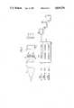
- FIG. 7is a schematic version of equipment used with a different embodiment of the invention, one in which three different images are developed.
- FIG. 8illustrates the transmission characteristic of filters used to tailor the detector characteristic and FIG. 9 shows the overall characteristic of the two filters.
- FIG. 10shows the arrangement of filters, detectors and circuitry.
- FIGS. 1 and 2are schematic illustrations of prior art flying spot scanning imaging systems; FIG. 1 illustrates a transmitted or transmission image scanning system, whereas FIG. 2 showed a scattered or backscattered flying spot scanning imaging system. Both FIGS. 1 and 2 are reproduced from the Stein et al publication referenced above.
- an x-ray tube 10(or other suitable source of penetrating radiant energy) emits a cone or fan-shaped beam 11 which impinges on a radiation opaque plate 20 having a slit 21 therein.
- a fan shaped beam 23is emitted from the plate 20 and impinges on a rotating collimator 30.
- the collimator 30has a plurality of slits 31, and as the plate 30 rotates in the direction 32, a pencil beam 34 is emitted from the collimation disk 30. As the disk 30 rotates, the pencil beam scans, and in FIGS. 1 and 2 that scanning action is vertically downward. Those skilled in the art will appreciate that the scanning motion of the pencil beam 34 can be reoriented within wide limits. As the pencil beam 34 scans, it illuminates the object 50. This illumination of the object 50 produces an attenuated pencil beam 35 (which is a theoretical extension of the pencil beam 34), e.g. it is a transmitted beam. At the same time, some of the penetrating radiant energy is backscattered, such as the radiation 36 shown in FIG. 2. In the case of FIG.
- a detector 45is arranged to intercept the transmitted, degraded pencil beam 35.
- the detector 45converts the x-ray energy to electrical signals, in a manner well known to those skilled in the art, and those signals are used to drive a video storage and display apparatus 70.
- the signals produced by the detector 45represent the x-ray transmissivity of the object, or at least that portion of the object which is illuminated by the pencil beam 34.
- the video storage and display 70produces an image of the x-ray transmissivity of that portion of the object.
- the objectmay be supported such as by the conveyor 60, and relative motion induced between the object 50 and the source 10, detector 45.
- One way of implementing that relative motionis to provide for motion of the conveyor 60 in the direction of the arrow 61.
- the detector 45is arranged to lie along a line in space which is scanned by the pencil beam 34 as the collimating disk 30 rotates. The relative motion then is motion between the object 50 and the detector 45.
- the detector 45is eliminated in favor of a backscatter detector 40 which comprises a pair of backscatter detector elements 41 and 42 placed on either side of the pencil beam 34.
- the backscatter detectorspreferably have a wide active area.
- the active arearefers to the detector area in the plane through which photons cross the detector boundary. It is clear that (in sharp contrast to the active area of the scatter detector) the active area of the transmitted beam detector is determined by the pencil beam cross-section and the extent of the beam's sweep. Nevertheless, it is within the scope of the invention to use only a single backscatter detector, such as the detector 41 or 42.
- the active area of the backscatter detectoris typically many times the active area of the transmission detector, such as the detector 45.
- the backscatter detector 40produces a single signal which is input to the video storage and display apparatus 70 and used to develop an image of the object 50 which is illuminated by PG,11 the scanning pencil beam 34.
- the image developed by the apparatus of FIG. 1represents the x-ray transmissivity of the object 50
- the image developed by the apparatus of FIG. 2is based on the energy scattered by the object 50. This energy is a strong function of the atomic number (Z) of the object 50 or its components in that strong backscatter is developed by components of low atomic number (Z) and high atomic number components contribute little, if any, to such an image.
- FIG. 3is useful in explaining why in many cases prior art projection radiographs were not dependable as flaw detection instruments.
- FIG. 3shows the cross-section of an object 50 including flaws 51 and 52 located therein.
- both flawsare mass or structural defects, such as a crack.
- the illuminating energytravels in the direction of the arrow 80. Since the projection radiograph represents the transmissivity of various lines of sight, and recognition of a flaw depends on recognizable contrast differences, it should be apparent that the flaw 51 may be readily recognized since adjacent lines of sight such as 800 and 801, on the one hand, and 801 and 802, on the other hand, will exhibit significant differences in transmissivity.
- typical lines of sightsuch as lines of sight 803-810 will represent little or no contrast relative to adjacent lines of sight.
- the flaw 51may well be readily detected, the flaw 52 will be invisible or near-invisible. Accordingly, the ability of the typical projection radiograph to detect a crack or flaw depends on part on the orientation of the crack or flaw. In general this makes the technique unreliable.
- FIG. 4illustrates a typical projection radiograph of an object which includes a number of density and/or other material variations, such that the radiograph shows a number of such variations 81.
- FIG. 4also shows a crack or a flaw 82 (or more accurately a representation of the crack or flaw) which appears on the projection radiograph.
- the problem represented in FIG. 4is difficulty of separating the crack or flaw 82 from other material variations, such as the variations 81 which do not represent cracks or flaws.
- the problems illustrated in FIGS. 3 and 4call for some apparatus or technique to highlight or otherwise call attention to a crack or a flaw regardless of the orientation of the crack or flaw and regardless of other, inherent variations.
- the apparatus of FIG. 2Prior to imaging, the object has applied to it a contrast agent.
- the contrast agentis characterized, or has a component which is characterized, by an atomic number which is selected to sharply contrast with the atomic number which characterizes the object to be imaged.
- the contrast agentmay be in gas or liquid phase depending on the type of crack or flaw to be detected and the characteristics of the object to be imaged.
- the steel plateis characterized by a high atomic number and therefore the contrast agent employed would be characterized by a low atomic number or at least have a component which is characterized by a low atomic number.
- recognition of a crack or flawmay well depend on the orientation of the crack or flaw. If the backscatter imaging (of FIG. 2) is employed, it too may not reveal the crack or flaw. Both steel and the air which is assumed to occupy the crack or flaw 51 and 52 are poor scattering materials and therefore the scatter image would have little or no signal.
- the inventionis not limited to enhancing flaws in high atomic number materials.
- the contrast agentwould be one which is characterized, or which has a component characterized, by a high atomic number.
- the resulting scatter imagewould highlight the cracks or flaws since while the object 50 being imaged is a good scattering material, the cracks or flaws would be poor scattering materials providing the desired contrast.
- the apparatus of FIG. 2can be employed in a second embodiment of the invention which is especially useful for imaging cracks or flaws in objects characterized by low atomic numbers.
- the contrast mediumis selected as one which is or has a component providing a predetermined fluorescent radiation line in response to illuminating radiant energy of preselected energy levels.
- the quantum of fluorescent radiation seen from any objectis a strong function of the atomic number of the material and the energy of the exciting radiation. In order for the fluorescent radiation to be detectable, it must have sufficient energy to escape the object within which it is generated. For this reason, contrast media represented or characterized by low atomic numbers are poor sources for fluorescent radiation since the fluorescent radiation they product typically has insufficient energy to escape the object and is therefore relatively undetectable.
- contrast mediawhich are characterized by or have a component which is characterized by a high atomic number will be capable of emitting fluorescent radiation of sufficient energy to escape the object being illuminated.
- Two examples of such contrast mediaare iodinated oils and barium.
- a further gaseous contrast mediumis xenon.
- all threeare characterized by high atomic number. So long as the exciting energy, e.g. the pencil beam 34, has sufficient energy to produce fluorescence, the fluorescence produced by the contrast medium is capable of being detected by the detectors 40.
- fluorescent radiationcomes off at a wide variety of angles and therefore use of a detector with a large active area is preferable.
- the energy level of the pencil beam 34When relying on fluorescent radiation for crack or flaw enhancement, the energy level of the pencil beam 34 must be selected to be capable of exciting the fluorescence.
- the energy of the illuminating or incident photonsmust be above the K-absorption edge for the material of interest.
- the peak voltageFor a typical x-ray (polychromatic) source, the peak voltage must be significantly higher than the K-absorption edge to ensure that many of the photons exceed the threshold value. Those photons below the K-edge are useless for fluorescence and might be filtered out of the illumination beam.
- the detector 40must be tailored to ensure that the signals produced by the detector are related to the predetermined fluorescent radiation line which is expected to be emitted by the contrast agent to the exclusion of signals representing other scattered radiation.
- the predetermined fluorescent radiation line which will be usedhas been selected, those skilled in the art are aware of conventional techniques for tailoring the detector response so as to respond essentially only to the predetermined fluorescent radiation line to the exclusion of other, scattered radiation.
- One suitable technique for tailoring the detector so that it responds to the predetermined fluorescent radiation line but does not respond to scattered radiationis to employ two conventional detectors (scintillators) each preceded by a filter. Since each element is reasonably transparent to its own fluorescent radiation, one of the filters is made of the material of interest, see FIG. 8. The thickness of the filter F1 is adjusted to produce a significant difference in attenuation across the K-edge. Thus, element F1 will differentially filter out x-rays just above the K-edge. The second filter has a slightly higher Z material but a nearly identical transmission characteristic with its K-edge displaced to a higher energy. The difference between the energy observed in the two detectors will be proportional to the energy in a tight region around the fluorescent line of interest and in this way focus on the fluorescent radiation line to the exclusion of (almost all) scattered radiation.
- FIG. 10shows an arrangement for tailoring the response of the detector 40 so that it responds substantially only to the predetermined fluorescent radiation line.
- FIG. 8shows how the characteristic of the filters consisting of elements F1 and F2 restricts the response of the detector 41 to the predetermined fluorescent radiation line, the energy in the vicinity of K.sub. ⁇ . More particularly, FIG. 8 (labelled transmission), shows the transmission characteristics of the filter elements F1 and F2, respectively. The discontinuity in these transmission characteristics is a result of a particular K-edge.
- FIG. 8also shows the location of the predetermined fluorescent radiation line K.sub. ⁇ .
- FIG. 9shows, in the lower curve (labelled ⁇ transmission), the energy characteristic passing the detector arrangement of FIG. 10. As shown in FIG.
- the energy characteristicis relatively flat until an energy approximately equal to the K-edge discontinuity in the transmission characteristic of element F1.
- the composite transmissionquickly rises, and it maintains this particular transmission characteristic as energy increases until an energy level is reached which is above K.sub. ⁇ , corresponding to the K-edge discontinuity in the characteristic of filter element F2.
- the composite transmission characteristicis substantially the lower level exhibited for energies below the K-edge associated with the filter element F1.
- the filter F-can comprise material identical to the targeted component.
- the second filter F2comprises a material of higher Z and a nearly identical transmission characteristic except near the K-edge.
- FIG. 10shows an arrangement for achieving the characteristic such as that shown in FIG. 9.
- the detector 41is split into two detector elements 41A and 41B, both located so as to detect the scattered energy 36.
- a first filter element F1is located between a source of the predetermined fluorescent radiation line and the detector element 41A
- a different filter element F2is located between a different detector element 41B and the source of the predetermined fluorescent radiation line.
- Each of these detectorsdevelops a signal corresponding to the intensity of the energy impinging on the detector.
- the signal A produced from the element 41Areflects the energy passing the filter element F1 and the signal B reflects the energy passing the filter element F2.
- a difference circuitproduces, at an output, the difference (A-B).
- FIG. 10produces an output signal (A-B) which, as a function of energy level, has the characteristic shown in FIG. 9.
- the output of (A-B)is the output of the detector 41.
- the two detector elements 41A and 41Bare arranged symmetrically with respect to the scattered energy 36. If both detector elements 41 and 42 are arranged as in FIG. 10, then, for example, element 42A and 41B are located closer to the illuminating beam than elements 42B and 41A, respectively.
- FIG. 5shows the apparatus that can be employed.
- FIG. 5shows an equipment cabinet 160 which can house the source of the flying pencil beam 34, e.g. the x-ray tube 10, slit collimator 20, rotating collimator 30.
- the flying pencil beam 34is emitted from the cabinet 160 and scans in a plane located between the detectors 41 and 42 (shown dotted in FIG. 5).
- the transmission detector 45is also shown in FIG. 5.
- Both the detectors 40 (scatter detectors) and 45 (transmit detector)generate the corresponding signals when an object is illuminated by the flying pencil beam 34.
- FIG. 6represents, in schematic fashion, the apparatus represented in FIGS. 1, 2 and 5.
- the signals produced by the scatter detector 40is input to the scatter electronics 251.
- the output of the scatter electronics 251is input to a display 252 which therefore displays a scatter image of the object 51 which is illuminated by the flying pencil beam 34.
- the output of the detector 45is input to the transmitted electronics 51, the output signal of which is provided to a display 502.
- the display 502develops a transmission image of the object 51.
- a suitable contrast agentis applied to the object 51 prior to imaging.
- the contrast agentmay be either gaseous or liquid and suitably selected with an appropriate atomic number, to provide a desired effect.
- the contrast agentin order to provide contrast in both transmission and scatter images, the contrast agent can be selected with these two criteria in mind.
- a suitable contrast mediumfor example for detecting flaws in low atomic number material would be an iodinated oil.
- the iodine componentprovides contrast in the transmission image and the oil based carrier supplies contrast in the scatter image.
- FIGS. 5 and 6also represent the equipment employed in still another embodiment of the invention.
- the detectors 40are tailored (as described with reference to FIGS. 8-10) to respond to a predetermined fluorescence radiation line and thus the detector 40, electronics 251 and display 252 provide a fluorescence image.
- the x-ray tube 10must provide x-rays of energy level sufficient to excite the predetermined fluorescence radiation line.
- the iodine in the iodinated oilprovides contrast in the fluorescence image as well as in the transmission image.
- FIG. 7illustrates, in schematic fashion, equipment employed in still another embodiment of the invention.
- FIG. 7differs from FIGS. 5 and 6 in that, in addition to the scatter detectors 41 and 42 and the transmission detector 45, there is an additional detector 90 comprising detector elements 91 and 92.
- the detector elements 91 and 92have their characteristics tailored to respond substantially only to a predetermined fluorescent radiation line.
- the signals provided by the detector 90are input to a fluorescent electronics element 601, the output of which drives the display 602.
- the display 502develops a transmission image
- the display 252develops a backscatter image
- the display 602develops a fluorescent image.
- the characteristics of the detector 90are tailored to respond substantially only to the predetermined fluorescence radiation line and the energy level in the x-ray tube 10 is selected so as to excite this predetermined fluorescence radiation line either in the contrast medium or in the object being illuminated.
- the contrast mediumagain is an iodinated oil
- the iodine componentprovides contrast in transmission and fluorescence
- the oil based carrierprovides contrast in scatter.
- the scatter detectorin the preceding description of various embodiments of the invention, we have referred to the scatter detector as being of backscatter (that is, placed on the same side of the object being imaged as was the source).
- the backscatter detector 40can be replaced by a forward scatter detector, e.g. on the other side of the object being imaged than the source.
- FIGS. 5 and 6it is also within the scope of the invention to develop scatter and fluorescent images.
- a further variation on the embodiments shown in FIG. 7is to develop fluorescent and forward scatter images as well as the transmitted image.
- any high atomic number contrast agentcan be used so long as it meets two criteria: (1) its atomic number shows an atomic number difference ( ⁇ Z) between the atomic number of the contrast agent and the atomic number of the material being imaged which exceeds some threshold and (2) the contrast agent has physical characteristics allowing it to penetrate cracks, etc.
Landscapes
- Physics & Mathematics (AREA)
- Health & Medical Sciences (AREA)
- Life Sciences & Earth Sciences (AREA)
- Chemical & Material Sciences (AREA)
- Analytical Chemistry (AREA)
- Biochemistry (AREA)
- General Health & Medical Sciences (AREA)
- General Physics & Mathematics (AREA)
- Immunology (AREA)
- Pathology (AREA)
- Analysing Materials By The Use Of Radiation (AREA)
Abstract
Description
Claims (8)
Priority Applications (1)
| Application Number | Priority Date | Filing Date | Title |
|---|---|---|---|
| US07/040,019US4819256A (en) | 1987-04-20 | 1987-04-20 | Radiographic sensitivity for detection of flaws and cracks |
Applications Claiming Priority (1)
| Application Number | Priority Date | Filing Date | Title |
|---|---|---|---|
| US07/040,019US4819256A (en) | 1987-04-20 | 1987-04-20 | Radiographic sensitivity for detection of flaws and cracks |
Publications (1)
| Publication Number | Publication Date |
|---|---|
| US4819256Atrue US4819256A (en) | 1989-04-04 |
Family
ID=21908633
Family Applications (1)
| Application Number | Title | Priority Date | Filing Date |
|---|---|---|---|
| US07/040,019Expired - LifetimeUS4819256A (en) | 1987-04-20 | 1987-04-20 | Radiographic sensitivity for detection of flaws and cracks |
Country Status (1)
| Country | Link |
|---|---|
| US (1) | US4819256A (en) |
Cited By (32)
| Publication number | Priority date | Publication date | Assignee | Title |
|---|---|---|---|---|
| US5113422A (en)* | 1991-07-01 | 1992-05-12 | The United States Of America As Represented By The Secretary Of The Air Force | Radiographic interpretation trainer/test system |
| US5167734A (en)* | 1990-03-30 | 1992-12-01 | General Electric Company | Process for identification evaluation and removal of microshrinkage |
| US5742658A (en)* | 1996-05-23 | 1998-04-21 | Advanced Micro Devices, Inc. | Apparatus and method for determining the elemental compositions and relative locations of particles on the surface of a semiconductor wafer |
| US5917880A (en)* | 1997-05-29 | 1999-06-29 | Eg&G Astrophysics | X-ray inspection apparatus |
| US6005915A (en)* | 1997-11-07 | 1999-12-21 | Advanced Micro Devices, Inc. | Apparatus and method for measuring the roughness of a target material surface based upon the scattering of incident X-ray photons |
| US6094472A (en)* | 1998-04-14 | 2000-07-25 | Rapiscan Security Products, Inc. | X-ray backscatter imaging system including moving body tracking assembly |
| US6278115B1 (en)* | 1998-08-28 | 2001-08-21 | Annistech, Inc. | X-ray inspection system detector with plastic scintillating material |
| US6665373B1 (en) | 2002-03-12 | 2003-12-16 | Rapiscan Security Products (Usa), Inc. | X-ray imaging system with active detector |
| US20040213375A1 (en)* | 2003-04-25 | 2004-10-28 | Paul Bjorkholm | Radiation sources and radiation scanning systems with improved uniformity of radiation intensity |
| US20050117701A1 (en)* | 2003-12-01 | 2005-06-02 | Nelson James M. | Backscatter imaging using hadamard transform masking |
| US20050220335A1 (en)* | 2004-03-30 | 2005-10-06 | Budd Gerald W | Surface inspection technology for the detection of porosity and surface imperfections on machined metal surfaces |
| US7110493B1 (en) | 2002-02-28 | 2006-09-19 | Rapiscan Security Products (Usa), Inc. | X-ray detector system having low Z material panel |
| US20100034451A1 (en)* | 2007-06-21 | 2010-02-11 | Hughes Ronald J | Systems and Methods for Improving Directed People Screening |
| US7826589B2 (en) | 2007-12-25 | 2010-11-02 | Rapiscan Systems, Inc. | Security system for screening people |
| US20110129063A1 (en)* | 2009-11-18 | 2011-06-02 | Joseph Bendahan | X-Ray-Based System and Methods for Inspecting a Person's Shoes for Aviation Security Threats |
| US8003949B2 (en) | 2007-11-01 | 2011-08-23 | Rapiscan Systems, Inc. | Multiple screen detection systems |
| US8135112B2 (en) | 2007-02-01 | 2012-03-13 | Rapiscan Systems, Inc. | Personnel security screening system with enhanced privacy |
| US8314394B1 (en) | 2009-11-04 | 2012-11-20 | Science Applications International Corporation | System and method for three-dimensional imaging using scattering from annihilation coincidence photons |
| US8576989B2 (en) | 2010-03-14 | 2013-11-05 | Rapiscan Systems, Inc. | Beam forming apparatus |
| US8576982B2 (en) | 2008-02-01 | 2013-11-05 | Rapiscan Systems, Inc. | Personnel screening system |
| US8995619B2 (en) | 2010-03-14 | 2015-03-31 | Rapiscan Systems, Inc. | Personnel screening system |
| US20160069824A1 (en)* | 2014-09-05 | 2016-03-10 | The Boeing Company | Nonaqueous Radiopaque Fluid and Associated Imaging System and Method |
| US9285325B2 (en) | 2007-02-01 | 2016-03-15 | Rapiscan Systems, Inc. | Personnel screening system |
| US9891314B2 (en) | 2014-03-07 | 2018-02-13 | Rapiscan Systems, Inc. | Ultra wide band detectors |
| US9989482B2 (en) | 2016-02-16 | 2018-06-05 | General Electric Company | Methods for radiographic and CT inspection of additively manufactured workpieces |
| US10134254B2 (en) | 2014-11-25 | 2018-11-20 | Rapiscan Systems, Inc. | Intelligent security management system |
| US10720300B2 (en) | 2016-09-30 | 2020-07-21 | American Science And Engineering, Inc. | X-ray source for 2D scanning beam imaging |
| US11280898B2 (en) | 2014-03-07 | 2022-03-22 | Rapiscan Systems, Inc. | Radar-based baggage and parcel inspection systems |
| US11291418B2 (en)* | 2018-05-16 | 2022-04-05 | Hologic, Inc. | Backscattering x-ray imager with x-ray source at detector center |
| US11543322B2 (en)* | 2020-05-01 | 2023-01-03 | Globalfoundries U.S. Inc. | Crack identification in IC chip package using encapsulated liquid penetrant contrast agent |
| US11778717B2 (en) | 2020-06-30 | 2023-10-03 | VEC Imaging GmbH & Co. KG | X-ray source with multiple grids |
| US12230468B2 (en) | 2022-06-30 | 2025-02-18 | Varex Imaging Corporation | X-ray system with field emitters and arc protection |
Citations (18)
| Publication number | Priority date | Publication date | Assignee | Title |
|---|---|---|---|---|
| US28544A (en)* | 1860-06-05 | Ditching-machine | ||
| US3197638A (en)* | 1963-01-21 | 1965-07-27 | Kenneth F Sinclair | Backscatter flaw detection system |
| US3351760A (en)* | 1963-08-26 | 1967-11-07 | Robert L Brown | Methods of evaluating and inspecting adhesively bonded joints and structures adapted for such evaluation and inspection |
| US3704370A (en)* | 1971-04-09 | 1972-11-28 | Us Air Force | Radiographic inspection technique |
| USRE28544E (en) | 1971-07-07 | 1975-09-02 | Radiant energy imaging with scanning pencil beam | |
| US3965353A (en)* | 1974-12-06 | 1976-06-22 | Albert Macovski | Cross-sectional X-ray emission imaging system |
| US3974386A (en)* | 1974-07-12 | 1976-08-10 | Wisconsin Alumni Research Foundation | Differential X-ray method and apparatus |
| US4172224A (en)* | 1978-10-24 | 1979-10-23 | The United States Of America As Represented By The United States Department Of Energy | Process for the detection of micro-cracks |
| US4178513A (en)* | 1978-01-17 | 1979-12-11 | Nuclear Semiconductor | Art object analyzer |
| US4227081A (en)* | 1979-06-13 | 1980-10-07 | The United States Of America As Represented By The United States Department Of Energy | Method of evaluating the integrity of the outer carbon layer of triso-coated reactor fuel particles |
| US4323973A (en)* | 1979-12-20 | 1982-04-06 | Greenfield George B | Apparatus and method for enhancing radiographs |
| US4355331A (en)* | 1981-01-28 | 1982-10-19 | General Electric Company | X-ray image subtracting system |
| US4400618A (en)* | 1981-08-06 | 1983-08-23 | International Business Machines Corporation | Method of detecting and analyzing damage in printed circuit boards |
| US4577337A (en)* | 1984-05-21 | 1986-03-18 | Southwest Research Institute | X-Ray fluorescence testing of laminate structures |
| US4591478A (en)* | 1983-08-26 | 1986-05-27 | The United States Of America As Represented By The Department Of Energy | Method of identifying defective particle coatings |
| US4618928A (en)* | 1982-12-06 | 1986-10-21 | Tokyo Shibaura Denki Kabushiki Kaisha | Data processing apparatus for producing X-ray images with improved signal to noise ratio |
| US4621193A (en)* | 1984-11-21 | 1986-11-04 | Michael Van Hoye | Fluorescent penetrant crack detection |
| US4686694A (en)* | 1980-12-15 | 1987-08-11 | Ramsey Engineering Company | Probe for an apparatus for analyzing metals by X-ray fluorescence |
- 1987
- 1987-04-20USUS07/040,019patent/US4819256A/ennot_activeExpired - Lifetime
Patent Citations (18)
| Publication number | Priority date | Publication date | Assignee | Title |
|---|---|---|---|---|
| US28544A (en)* | 1860-06-05 | Ditching-machine | ||
| US3197638A (en)* | 1963-01-21 | 1965-07-27 | Kenneth F Sinclair | Backscatter flaw detection system |
| US3351760A (en)* | 1963-08-26 | 1967-11-07 | Robert L Brown | Methods of evaluating and inspecting adhesively bonded joints and structures adapted for such evaluation and inspection |
| US3704370A (en)* | 1971-04-09 | 1972-11-28 | Us Air Force | Radiographic inspection technique |
| USRE28544E (en) | 1971-07-07 | 1975-09-02 | Radiant energy imaging with scanning pencil beam | |
| US3974386A (en)* | 1974-07-12 | 1976-08-10 | Wisconsin Alumni Research Foundation | Differential X-ray method and apparatus |
| US3965353A (en)* | 1974-12-06 | 1976-06-22 | Albert Macovski | Cross-sectional X-ray emission imaging system |
| US4178513A (en)* | 1978-01-17 | 1979-12-11 | Nuclear Semiconductor | Art object analyzer |
| US4172224A (en)* | 1978-10-24 | 1979-10-23 | The United States Of America As Represented By The United States Department Of Energy | Process for the detection of micro-cracks |
| US4227081A (en)* | 1979-06-13 | 1980-10-07 | The United States Of America As Represented By The United States Department Of Energy | Method of evaluating the integrity of the outer carbon layer of triso-coated reactor fuel particles |
| US4323973A (en)* | 1979-12-20 | 1982-04-06 | Greenfield George B | Apparatus and method for enhancing radiographs |
| US4686694A (en)* | 1980-12-15 | 1987-08-11 | Ramsey Engineering Company | Probe for an apparatus for analyzing metals by X-ray fluorescence |
| US4355331A (en)* | 1981-01-28 | 1982-10-19 | General Electric Company | X-ray image subtracting system |
| US4400618A (en)* | 1981-08-06 | 1983-08-23 | International Business Machines Corporation | Method of detecting and analyzing damage in printed circuit boards |
| US4618928A (en)* | 1982-12-06 | 1986-10-21 | Tokyo Shibaura Denki Kabushiki Kaisha | Data processing apparatus for producing X-ray images with improved signal to noise ratio |
| US4591478A (en)* | 1983-08-26 | 1986-05-27 | The United States Of America As Represented By The Department Of Energy | Method of identifying defective particle coatings |
| US4577337A (en)* | 1984-05-21 | 1986-03-18 | Southwest Research Institute | X-Ray fluorescence testing of laminate structures |
| US4621193A (en)* | 1984-11-21 | 1986-11-04 | Michael Van Hoye | Fluorescent penetrant crack detection |
Non-Patent Citations (2)
| Title |
|---|
| Stein et al., "Flying Spot X-Ray Imaging Systems", Materials Evaluation, vol. 30, No. 7, Jul. 1972, p. 137 et seq. |
| Stein et al., Flying Spot X Ray Imaging Systems , Materials Evaluation, vol. 30, No. 7, Jul. 1972, p. 137 et seq.* |
Cited By (47)
| Publication number | Priority date | Publication date | Assignee | Title |
|---|---|---|---|---|
| US5167734A (en)* | 1990-03-30 | 1992-12-01 | General Electric Company | Process for identification evaluation and removal of microshrinkage |
| US5113422A (en)* | 1991-07-01 | 1992-05-12 | The United States Of America As Represented By The Secretary Of The Air Force | Radiographic interpretation trainer/test system |
| US5742658A (en)* | 1996-05-23 | 1998-04-21 | Advanced Micro Devices, Inc. | Apparatus and method for determining the elemental compositions and relative locations of particles on the surface of a semiconductor wafer |
| US5917880A (en)* | 1997-05-29 | 1999-06-29 | Eg&G Astrophysics | X-ray inspection apparatus |
| US6005915A (en)* | 1997-11-07 | 1999-12-21 | Advanced Micro Devices, Inc. | Apparatus and method for measuring the roughness of a target material surface based upon the scattering of incident X-ray photons |
| US6094472A (en)* | 1998-04-14 | 2000-07-25 | Rapiscan Security Products, Inc. | X-ray backscatter imaging system including moving body tracking assembly |
| US6278115B1 (en)* | 1998-08-28 | 2001-08-21 | Annistech, Inc. | X-ray inspection system detector with plastic scintillating material |
| US7110493B1 (en) | 2002-02-28 | 2006-09-19 | Rapiscan Security Products (Usa), Inc. | X-ray detector system having low Z material panel |
| US6665373B1 (en) | 2002-03-12 | 2003-12-16 | Rapiscan Security Products (Usa), Inc. | X-ray imaging system with active detector |
| US6954515B2 (en) | 2003-04-25 | 2005-10-11 | Varian Medical Systems, Inc., | Radiation sources and radiation scanning systems with improved uniformity of radiation intensity |
| US20040213375A1 (en)* | 2003-04-25 | 2004-10-28 | Paul Bjorkholm | Radiation sources and radiation scanning systems with improved uniformity of radiation intensity |
| US20050117701A1 (en)* | 2003-12-01 | 2005-06-02 | Nelson James M. | Backscatter imaging using hadamard transform masking |
| US6950495B2 (en) | 2003-12-01 | 2005-09-27 | The Boeing Company | Backscatter imaging using Hadamard transform masking |
| US7394530B2 (en)* | 2004-03-30 | 2008-07-01 | Budd Gerald W | Surface inspection technology for the detection of porosity and surface imperfections on machined metal surfaces |
| US20050220335A1 (en)* | 2004-03-30 | 2005-10-06 | Budd Gerald W | Surface inspection technology for the detection of porosity and surface imperfections on machined metal surfaces |
| US9182516B2 (en) | 2007-02-01 | 2015-11-10 | Rapiscan Systems, Inc. | Personnel screening system |
| US9291741B2 (en) | 2007-02-01 | 2016-03-22 | Rapiscan Systems, Inc. | Personnel screening system |
| US9285325B2 (en) | 2007-02-01 | 2016-03-15 | Rapiscan Systems, Inc. | Personnel screening system |
| US8135112B2 (en) | 2007-02-01 | 2012-03-13 | Rapiscan Systems, Inc. | Personnel security screening system with enhanced privacy |
| US20100034451A1 (en)* | 2007-06-21 | 2010-02-11 | Hughes Ronald J | Systems and Methods for Improving Directed People Screening |
| US8774362B2 (en) | 2007-06-21 | 2014-07-08 | Rapiscan Systems, Inc. | Systems and methods for improving directed people screening |
| US8199996B2 (en) | 2007-06-21 | 2012-06-12 | Rapiscan Systems, Inc. | Systems and methods for improving directed people screening |
| US8148693B2 (en) | 2007-11-01 | 2012-04-03 | Rapiscan Systems, Inc. | Multiple screen detection systems |
| US8401147B2 (en) | 2007-11-01 | 2013-03-19 | Rapiscan Systems, Inc. | Multiple screen detection systems |
| US8003949B2 (en) | 2007-11-01 | 2011-08-23 | Rapiscan Systems, Inc. | Multiple screen detection systems |
| US7826589B2 (en) | 2007-12-25 | 2010-11-02 | Rapiscan Systems, Inc. | Security system for screening people |
| US8576982B2 (en) | 2008-02-01 | 2013-11-05 | Rapiscan Systems, Inc. | Personnel screening system |
| US8314394B1 (en) | 2009-11-04 | 2012-11-20 | Science Applications International Corporation | System and method for three-dimensional imaging using scattering from annihilation coincidence photons |
| US8426822B1 (en) | 2009-11-04 | 2013-04-23 | Science Application International Corporation | System and method for three-dimensional imaging using scattering from annihilation coincidence photons |
| US8664609B2 (en) | 2009-11-04 | 2014-03-04 | Leidos, Inc. | System and method for three-dimensional imaging using scattering from annihilation coincidence photons |
| US8654922B2 (en) | 2009-11-18 | 2014-02-18 | Rapiscan Systems, Inc. | X-ray-based system and methods for inspecting a person's shoes for aviation security threats |
| US20110129063A1 (en)* | 2009-11-18 | 2011-06-02 | Joseph Bendahan | X-Ray-Based System and Methods for Inspecting a Person's Shoes for Aviation Security Threats |
| US8995619B2 (en) | 2010-03-14 | 2015-03-31 | Rapiscan Systems, Inc. | Personnel screening system |
| US9058909B2 (en) | 2010-03-14 | 2015-06-16 | Rapiscan Systems, Inc. | Beam forming apparatus |
| US8576989B2 (en) | 2010-03-14 | 2013-11-05 | Rapiscan Systems, Inc. | Beam forming apparatus |
| US9891314B2 (en) | 2014-03-07 | 2018-02-13 | Rapiscan Systems, Inc. | Ultra wide band detectors |
| US11280898B2 (en) | 2014-03-07 | 2022-03-22 | Rapiscan Systems, Inc. | Radar-based baggage and parcel inspection systems |
| US9678022B2 (en)* | 2014-09-05 | 2017-06-13 | The Boeing Company | Nonaqueous radiopaque fluid and associated imaging system and method |
| US20160069824A1 (en)* | 2014-09-05 | 2016-03-10 | The Boeing Company | Nonaqueous Radiopaque Fluid and Associated Imaging System and Method |
| US10134254B2 (en) | 2014-11-25 | 2018-11-20 | Rapiscan Systems, Inc. | Intelligent security management system |
| US10713914B2 (en) | 2014-11-25 | 2020-07-14 | Rapiscan Systems, Inc. | Intelligent security management system |
| US9989482B2 (en) | 2016-02-16 | 2018-06-05 | General Electric Company | Methods for radiographic and CT inspection of additively manufactured workpieces |
| US10720300B2 (en) | 2016-09-30 | 2020-07-21 | American Science And Engineering, Inc. | X-ray source for 2D scanning beam imaging |
| US11291418B2 (en)* | 2018-05-16 | 2022-04-05 | Hologic, Inc. | Backscattering x-ray imager with x-ray source at detector center |
| US11543322B2 (en)* | 2020-05-01 | 2023-01-03 | Globalfoundries U.S. Inc. | Crack identification in IC chip package using encapsulated liquid penetrant contrast agent |
| US11778717B2 (en) | 2020-06-30 | 2023-10-03 | VEC Imaging GmbH & Co. KG | X-ray source with multiple grids |
| US12230468B2 (en) | 2022-06-30 | 2025-02-18 | Varex Imaging Corporation | X-ray system with field emitters and arc protection |
Similar Documents
| Publication | Publication Date | Title |
|---|---|---|
| US4819256A (en) | Radiographic sensitivity for detection of flaws and cracks | |
| US4839913A (en) | Shadowgraph imaging using scatter and fluorescence | |
| US5044002A (en) | Baggage inspection and the like | |
| US5313511A (en) | X-ray imaging particularly adapted for low Z materials | |
| US5181234A (en) | X-ray backscatter detection system | |
| US5642394A (en) | Sidescatter X-ray detection system | |
| US4974247A (en) | System for radiographically inspecting an object using backscattered radiation and related method | |
| US7236564B2 (en) | Linear array detector system and inspection method | |
| AU2007252162B2 (en) | Energy spectra modulating device,method and device of identifying materials and method of image processing | |
| US3790799A (en) | Radiant energy imaging with rocking scanning | |
| EP0053167B1 (en) | Procedure and apparatus for examining the surface quality of solid materials | |
| US4577337A (en) | X-Ray fluorescence testing of laminate structures | |
| KR870002812A (en) | Scattering method in X-ray imaging | |
| US3928765A (en) | Determining composition of a substance by the use of both reflected and transmitted radiation | |
| US6873680B2 (en) | Method and apparatus for detecting defects using digital radiography | |
| US4736397A (en) | Radiation image inspection apparatus | |
| US3779649A (en) | Method of and an electro-optical system for inspecting material | |
| Poranski et al. | X-ray backscatter tomography: NDT potential and limitations | |
| IL99098A (en) | X-ray backscatter detection system | |
| US7062012B1 (en) | Leak detection of sealed objects using x-ray imaging | |
| JPH06503877A (en) | Imaging methods for defining the structure of objects | |
| CN111982942A (en) | Non-destructive inspection method, system and apparatus using focusable X-ray backscatter detectors | |
| Mullin et al. | A Compton-scatter spectrometry technique for flaw detection | |
| US5753930A (en) | Device for translating negative film image to a line scan | |
| US3536915A (en) | Radiographic bond inspection apparatus |
Legal Events
| Date | Code | Title | Description |
|---|---|---|---|
| AS | Assignment | Owner name:AMERICAN SCIENCE AND ENGINEERING, INC., FORT WASHI Free format text:ASSIGNMENT OF ASSIGNORS INTEREST.;ASSIGNORS:ANNIS, MARTIN;BJORKHOLM, PAUL;REEL/FRAME:004757/0043;SIGNING DATES FROM 19870508 TO 19870518 | |
| STCF | Information on status: patent grant | Free format text:PATENTED CASE | |
| AS | Assignment | Owner name:UNITED STATES TRUST COMPANY, 30/40 COURT ST., BOST Free format text:ASSIGNMENT OF ASSIGNORS INTEREST.;ASSIGNOR:AMERICAN SCIENCE AND ENGINEERING, INC., A CORP. OF MA.;REEL/FRAME:005513/0323 Effective date:19900703 | |
| FEPP | Fee payment procedure | Free format text:PAYOR NUMBER ASSIGNED (ORIGINAL EVENT CODE: ASPN); ENTITY STATUS OF PATENT OWNER: SMALL ENTITY | |
| FPAY | Fee payment | Year of fee payment:4 | |
| FPAY | Fee payment | Year of fee payment:8 | |
| FEPP | Fee payment procedure | Free format text:PAYER NUMBER DE-ASSIGNED (ORIGINAL EVENT CODE: RMPN); ENTITY STATUS OF PATENT OWNER: SMALL ENTITY | |
| FPAY | Fee payment | Year of fee payment:12 | |
| AS | Assignment | Owner name:AMERICAN SCIENCE AND ENGINEERING, INC., MASSACHUSE Free format text:ASSIGNMENT OF ASSIGNORS INTEREST;ASSIGNOR:UNITED STATES TRUST COMPANY;REEL/FRAME:011137/0190 Effective date:20001128 | |
| AS | Assignment | Owner name:EXPORT-IMPORT BANK OF THE UNITED STATES, DISTRICT Free format text:SECURITY AGREEMENT;ASSIGNOR:AMERICAN SCIENCE AND ENGINEERING, INC.;REEL/FRAME:011277/0608 Effective date:20001130 | |
| AS | Assignment | Owner name:SILICON VALLEY BANK DBA SILICON VALLEY EAST, CALIF Free format text:SEURITY AGREEMENT;ASSIGNOR:AMERICAN SCIENCE AND ENGINEERING, INC.;REEL/FRAME:014007/0604 Effective date:20030811 | |
| AS | Assignment | Owner name:AMERICAN SCIENCE AND ENGINEERING, INC., MASSACHUSE Free format text:ASSIGNMENT OF ASSIGNORS INTEREST;ASSIGNOR:SILICON VALLEY BANK;REEL/FRAME:023556/0062 Effective date:20091118 |