US4818882A - Photoacoustic gas analyzer - Google Patents
Photoacoustic gas analyzerDownload PDFInfo
- Publication number
- US4818882A US4818882AUS07/052,596US5259687AUS4818882AUS 4818882 AUS4818882 AUS 4818882AUS 5259687 AUS5259687 AUS 5259687AUS 4818882 AUS4818882 AUS 4818882A
- Authority
- US
- United States
- Prior art keywords
- measuring chamber
- light
- gas analyzer
- measuring
- photoacoustic gas
- Prior art date
- Legal status (The legal status is an assumption and is not a legal conclusion. Google has not performed a legal analysis and makes no representation as to the accuracy of the status listed.)
- Expired - Lifetime
Links
Images


Classifications
- G—PHYSICS
- G01—MEASURING; TESTING
- G01N—INVESTIGATING OR ANALYSING MATERIALS BY DETERMINING THEIR CHEMICAL OR PHYSICAL PROPERTIES
- G01N21/00—Investigating or analysing materials by the use of optical means, i.e. using sub-millimetre waves, infrared, visible or ultraviolet light
- G01N21/17—Systems in which incident light is modified in accordance with the properties of the material investigated
- G01N21/1702—Systems in which incident light is modified in accordance with the properties of the material investigated with opto-acoustic detection, e.g. for gases or analysing solids
- G—PHYSICS
- G01—MEASURING; TESTING
- G01J—MEASUREMENT OF INTENSITY, VELOCITY, SPECTRAL CONTENT, POLARISATION, PHASE OR PULSE CHARACTERISTICS OF INFRARED, VISIBLE OR ULTRAVIOLET LIGHT; COLORIMETRY; RADIATION PYROMETRY
- G01J1/00—Photometry, e.g. photographic exposure meter
- G01J1/42—Photometry, e.g. photographic exposure meter using electric radiation detectors
- G01J2001/4242—Modulated light, e.g. for synchronizing source and detector circuit
- G—PHYSICS
- G01—MEASURING; TESTING
- G01N—INVESTIGATING OR ANALYSING MATERIALS BY DETERMINING THEIR CHEMICAL OR PHYSICAL PROPERTIES
- G01N21/00—Investigating or analysing materials by the use of optical means, i.e. using sub-millimetre waves, infrared, visible or ultraviolet light
- G01N21/01—Arrangements or apparatus for facilitating the optical investigation
- G01N21/03—Cuvette constructions
- G01N21/05—Flow-through cuvettes
- G01N2021/052—Tubular type; cavity type; multireflective
- G—PHYSICS
- G01—MEASURING; TESTING
- G01N—INVESTIGATING OR ANALYSING MATERIALS BY DETERMINING THEIR CHEMICAL OR PHYSICAL PROPERTIES
- G01N21/00—Investigating or analysing materials by the use of optical means, i.e. using sub-millimetre waves, infrared, visible or ultraviolet light
- G01N21/17—Systems in which incident light is modified in accordance with the properties of the material investigated
- G01N21/1702—Systems in which incident light is modified in accordance with the properties of the material investigated with opto-acoustic detection, e.g. for gases or analysing solids
- G01N2021/1704—Systems in which incident light is modified in accordance with the properties of the material investigated with opto-acoustic detection, e.g. for gases or analysing solids in gases
- G—PHYSICS
- G01—MEASURING; TESTING
- G01N—INVESTIGATING OR ANALYSING MATERIALS BY DETERMINING THEIR CHEMICAL OR PHYSICAL PROPERTIES
- G01N21/00—Investigating or analysing materials by the use of optical means, i.e. using sub-millimetre waves, infrared, visible or ultraviolet light
- G01N21/17—Systems in which incident light is modified in accordance with the properties of the material investigated
- G01N21/25—Colour; Spectral properties, i.e. comparison of effect of material on the light at two or more different wavelengths or wavelength bands
- G01N21/31—Investigating relative effect of material at wavelengths characteristic of specific elements or molecules, e.g. atomic absorption spectrometry
- G01N2021/3129—Determining multicomponents by multiwavelength light
Definitions
- the inventionrelates to a photoacoustic gas analyzer comprising a measuring chamber, a modulated light source, and at least one microphone connected with the measuring chamber and measuring the changes of pressure caused by the absorption of the light within the chamber.
- the above measuring methodutilizes the fact that molecules absorb light such as for instance infrared light at predetermined wave lengths.
- the position of the absorption bandsdepends on the substance.
- the infrared lightis modulated and an acoustic signal is generated in the measuring chamber, said signal being proportional to the concentration and having a frequency corresponding to the modulation frequency.
- a known method for measuring the gas concentrationis the so-called transmission method, cf. U.S. Pat. No. 3,562,524. This method is based on a measurement of how much the light is alternated at the passage of a gas cell, the difference in light intensity measured with and without the desired gas in the cell indicating the gas concentration. The reliability of the measurement is consequently rather low at low gas concentrations.
- the above draw-backis avoided by the photoacoustic measuring method because the signal provided by this method is directly proportional to the gas concentration and not--as in the transmission method--proportional to the difference between two almost equal values.
- This methodis therefore particularly suited for measuring low gas concentrations provided the light intensity within the measuring chamber is sufficiently high.
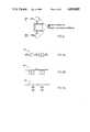
- a known photoacoustic measuring method with a high sensitivityis based on the use of a laser as light source, cf. FIG. 1, the latter partly utilizing the great light power emitted e.g. by a carbon dioxide laser and partly the collimated nature of the light emitted.
- the light source of the laseris, however, not very flexible concerning a variation of the wave length.
- a high-energy lasersuch as a carbon dioxide laser is expensive, heavy, and large and therefore not suited for mass production.
- the almost parallel lightis a condition by the known photoacoustic measuring method and may, of course, derive from another type of light source such as a thermal light source or a spectral lamp instead of the light source of the laser.
- a high flexibility concerning the choice of wave lengthis obtained for instance by using an optical filter for the selection of the desired wave length interval.
- Such a light sourceis furthermore inexpensive, small, and easy and therefore suited for mass production.
- the intensity of an almost parallel light beam deriving from said sourcesis, however, very low as it is proportional to sin 2 ⁇ , where ⁇ is the angle of divergence of the light.
- a highly divergent light focussed on the measuring chamberis used a highly increased light intensity is instead obtained.
- the latteris, however, encumbered with the draw-back that an essential part of the light hits the walls of the measuring chamber and is thereby partially absorbed.
- the measuring signalis partially reduced because only part of the light passes the measuring chamber, and furthermore a strong background signal is caused by the light power absorbed in the wall of the chamber.
- An object of the present inventionis to show how a photoacoustic transducer comprising for instance a thermal light source can provide a high sensitivity.
- the high sensitivityis obtained in two ways: Partly by maximizing the light intensity and consequently the signal level, and partly by minimizing disturbing signals.
- the present inventionprovides a photoacoustic measuring chamber, the alls of which reflect the light hitting said walls from the inside. In this manner the light entering the measuring chamber passes said chamber and thereby contributes to providing the desired gas signal. Furthermore the disturbing background signal is minimized as only a small part of the light is absorbed by the walls of the chamber.
- the background signalcan be further reduced by producing the walls of the chamber of a material of a high heat conductivity such as for instance copper with a thin layer of a reflecting coating such as gold.
- the light intensity in the measuring chamber and consequently the sensitivityare increased by a factor 2 when one window of the measuring chamber is replaced by a reflecting wall, the light then passing the measuring chamber twice.
- the measuring chambercomprises a hollow body of an arbitrary shape with walls of a highly heat-conducting material and with an inner reflecting coating.
- the light entering the measuring chamberis then reflected at the walls several times before leaving the chamber, whereby the intensity is amplified by a factor of up to 4.
- a spherical measuring chamberis an example of such a measuring chamber.
- a further amplification of the intensitycan be obtained by means of a concentrator allowing entry of light at an angle of incidence of ⁇ max .
- the lightis reflected therefrom and does not enter when ⁇ > ⁇ max .
- the divergence of the light leaving the concentratorhas then been increased, and the intensity is increased as well.
- a measuring chamber particularly suited for the ultraviolet fieldis provided with walls of a transparent dielectric material of a low heat conductivity such as quartz and with the reflecting coating such as aluminium being applied onto the outside of the measuring chamber. In this manner the wall background signal is considerably reduced.
- An infrared gas analyzer with two substantially uniform microphones connected to the measuring chamberallows a compensation for vibrations when the two uniform microphones are symmetrically situated relative to the centre of gravity of the air contained in the measuring chamber and the signals of the two microphones are added.
- the microphonesare shaped in a particular manner as the pressure-balancing channel from the back volume of each microphone usually extending to the surroundings here is connected to the volume of the closed measuring chamber. As a result, the disturbances due to acoustic noise from the outside are reduced.
- the transducerWhen the transducer is provided with an additional optical filter, i.e. a reference filter, and a mechanical device switching between the two filters it is possible to compensate for the disturbing signals such as the wall background signal, the signal from a possibly interfering gas or the water continuum signal.
- the latterderives from a slight wide-band absorption in water steam, i.e. the so-called "water continuum absorption".
- the modulator and the two filtersare combined into a rotating unit. i.e. the so-called differential filter modulator.
- a separate mechanical filter-switching deviceis avoided, and furthermore the signal-to-noise value is increased by 6 dB.
- the compensation of the water continuum signalcan be provided by a photoacoustic measurement of the water concentration by means of an electrically modulated glow lamp as light source instead of using a particular reference filter.
- the methodis based on the fact that the spectral distribution of the light from the glow lamp coincides with an absorption band positioned in the wave length interval 1.5-2.7 ⁇ , said spectral distribution being determined by the spectral characteristics of the glow lamp and the transmission characteristics of the lamp glass. Such a method is very simple and inexpensive.
- magnetic valvesare provided in the inlets of the measuring chamber. These magnetic valves close the measuring chamber during a measuring procedure, which ensures a further reduction of the acoustic noise.
- a measuring procedureis discontinuous and the time of response is rather long.
- the magnetic valvesare replaced by acoustic low-pass filters capable of strongly reducing acoustic noise from the outside at the modulator frequency. In this manner it is possible to measure continuously during the passage of gas, which ensures a short time of response. The sensitivity is, however, slightly reduced.
- the acoustic capacitycorresponds to the side volume not passed by the gas to be measured. In this manner the modulator frequency is highly reduced without sacrificing the short time of response.
- a transducer with a plurality of optical filters as well as a mechanical device for a sequential coupling thereofmakes is possible to perform a sequential measuring of the gas concentration in a mixture of several gases.
- a quick simultaneous parallel measuring of several gasescan be obtained by the transducer being formed in such a manner that the light is distributed between a number of permanent optical filters and by the modulator being formed in such a manner that the light corresponding to said filters is modulated at their respective frequency.
- the signals corresponding to the various gasesare separated through an electric filtration of the microphone signal.
- the inrared gas analyzercan be combined with a paramagnetic measuring apparatus and employ the same measuring microphones. Then the paramagnetic gas analyzer can be used for measuring the oxygen content whereas the infrared gas analyzer can be used for measuring the content of the remaining gases.
- FIG. 1illustrates a known photoacoustic measuring method employing a laser
- FIG. 2illustrates a photoacoustic measuring chamber with reflecting walls allowing the use of a divergent light from a thermal light source
- FIG. 3illustrates an example of a second embodiment of the measuring chamber
- FIG. 4illustrates the measuring chamber with a concentrator
- FIG. 5illustrates a measuring chamber of transparent dielectric material with an outer reflecting coating
- FIG. 6illustrates a compensation for vibration by means of two microphones
- FIG. 7lillustrates an example of a differential filtering modulator
- FIG. 8illustrates a measuring chamber with magnetic valves or acoustic low-pass filters in the inlets
- FIGS. 9a and 9billustrate acoustic filters
- FIG. 9cillustrates an electric filtering circuit
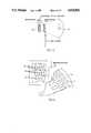
- FIG. 10illustrates a photoacoustic transducer for a simultaneous measurement of several gases of a mixture of gases
- FIG. 11is a front view of the modulator of FIG. 10,
- FIG. 12is a perspective view of an example of a measuring chamber
- FIG. 13illustrates a photoacoustic gas analyzer combined with a paramagnetic gas analyzer.
- FIG. 1illustrates a known prior art photoacoustic measuring system employing a laser 20, a modulator 22, a converging lens 24, a gas cell 26, a microphone 28, and an output amplifier 30.
- FIG. 2illustrates a photoacoustic measuring chamber 32 in the shape of a cylinder with a reflecting coating 34 on the interior walls, allowing the use of divergent light from a thermal light source 36.
- An ellipsoidal mirror 38converges the light through a modulator 40, an optical filter 42, and an entrance window 44, from which the light diverges into the cylindrical chamber 32, with a microphone 46 providing the output therefrom.
- the gas analyzer of FIG. 10comprises a measuring chamber 2 and a light source 4.
- a modulator 6 and a filter 8is placed between the measuring chamber 2 and the light source 4.
- the modulator 6is a rotating disc with apertures, cf. FIG. 11.
- the modulator 6causes emission of a pulsating light beam to the measuring chamber.
- the absorption within the measuring chamber 2 and the resulting heating of the gases contained thereinimply that an acoustic signal is generated in the measuring chamber 2.
- This signalis detected by means of a microphone 10 communicating with the measuring chamber.
- the acoustic signalis proportional to the concentration of the gas to be analyzed and possesses a frequency corresponding to the frequency of the modulator.
- FIG. 11illustrates the modulator 6 in connection with some stationary filter openings 11a, 11b, 11c transmitting infrared light at the wave lengths abosrbed by N 2 O, CO 2 , and anaesthetics, respectively.
- the lightis modulated simultaneously at three different frequencies. In this manner it is possible to measure the concentration of the three gases simultaneously.
- C Pis the amount of heat necessary for heating one mol of the gas by one degree at constant pressure (molar heatp C P )
- C vis the amount of heat necessary for heating one mol of the gas by one degree at constant volume (molar heat C v ).
- the sensitivityis thus proportional to the light intensity I. Furthermore it is inversely proportional to the modulator frequency ⁇ .
- the formulaapplies, however, only to a predetermined lower limit frequency depending on the size of the chamber.
- FIG. 12is a perspective view of an exemplary embodiment 48 of a measuring chamber of the type described herein.
- FIG. 3illustrates a spherical measuring chamber 12 having an internal reflecting coating 14 and a relatively small window 13.
- the light of the sourceis focussed by means of a mirror.
- the lightis heavily convergent which means that the entering light intensity is high.
- the inner surface of the spherical measuring chamberhas been polished and coated with a material being highly reflecting in the desired wave length interval, e.g. gold or rhodium.
- the light entering the measuring chamber 12is reflected several times before delivering from the chamber. In this manner the light intensity is amplified within the measuring chamber 12 compared to the entering light intensity.
- the maximum amplificationis 4 times.
- the divergent entering light and the amplification through the multireflectorensure a high sensitivity.
- a condition of the methodis a high reflection capacity, partly to maximize the amplification as much as possible and partly to reduce the background signal caused by part of the light being absorbed in the wall of the measuring chamber.
- the background signalcan also be reduced by a suitable choice of wall material, tellurium copper and copper. Such a material must possess a high heat conductivity and a high heat capacity.
- An additional amplification of the intensitycan be obtained by means of a concentrator 50 situated at the opening of the measuring chamber 52, cf. FIG. 4.
- the light leaving the concentratorcan be more divergent (up to ⁇ /2) than by means of a lense.
- the differential filter modulatorcomprises two rotating optical filters, e.g. the configuration of FIG. 7 including two crescent-shaped filters, said filters being a sample filter 60 and a reference filter 62, respectively.
- the reference filtercompensates for either the wall background, an interfering gas or a water continuum absorption.
- the differential filter modulatorit is possible to carry out the measuring sequentially by the first filter being switched on initially followed by a switching on of the second filter, said procedure being followed by an arithmetic compensation.
- the advantages of the filter modulatoris that no filter-switching device is necessary and furthermore a 6 dB higher signal-to-noise-ratio is obtained during the same measuring period (3 dB because the dark period of the modulator is utilized for the measuring as well as 3 dB because the difference is measured directly).
- spherical measuring chamber 54is provided with an outer reflecting coating, 56 cf. FIG. 5, whereby the wall background is reduced.
- the wallis made of a transparent material 58 and must be thermally thick, i.e. thicker than the thermal length of diffusion, said length of diffusion depending on the modulator frequency and the thermal properties of the material.
- a high heat conductivitymeans that the material possesses a long thermal length of diffusion, and then the wall must be extra thick.
- a cylindrical measuring chamber, 32 cf. FIG. 2is included, said embodiment being particularly suited for mass production.
- Such a chamberis easy to polish.
- the amplification of the intensityis reduced by a factor 2 compared to the spherical embodiment,
- FIG. 12is a perspective view of the measuring chamber, where it is possible to situate an optical filter in front of the measuring chamber.
- the measuring chamberis preferably situated in a block of tellurium copper, said material being easier to process than pure copper.
- the inner side of the measuring chamberis preferably coated with nickel and gold.
- a compensation for the water continuum signalnecessitates a measuring of the water concentration.
- the latteris carried out photoacousticly by means of the microphones and an electrically modulated glow lamp, the frequency characteristics of which correspond to 2.7 ⁇ of the water band.
- an arithmetic compensation based on the characteristics of each filteris carried out.
- the maximum cutoff frequency of the lamp glassis at 3 ⁇ and thus not particularly influenced by the CO 2 band at 4.27 ⁇ . Therefore the optical filter can be omitted.
- An electrically modulated glow lampallows omission of mechanical filter switches.
- the water continuun absorptionis a wide-band absorption in water steam.
- the absorption coefficientvaries "softly" with the wave length. Generally speaking it is proportional to the water concentration square unlike the actual absorption bands having line structure and where the absorption is proportional to the concentration.
- the above embodimentsare sensitive to vibrations.
- the vibration sensitivityis due partly to the mass of the membrane of the microphone, i.e. the membrane must consequently be thin, and partly to the mass of the air contained in the measuring.
- Two microphones 15, 16are used for reducing the above sensitivity and are turned oppositely, cf. FIG. 6. Furthermore they are symmetrically positioned about the centre of gravity of the air contained in the measuring chamber. The signals of the two microphones 15, 16 are summed whereby the vibrations are avoided. Uniform microphones are necessary for a simultaneous compensation of the vibration signal from both the air and the membrane. Such an embodiment ensues an increase of the signal power by 6 dB as well as an increase of the signal-to-noise-ratio by 3 dB.
- Each microphonemay furthermore be shaped in such a manner that the pressure-balancing channel communicates with the measuring chamber and not with the surroundings in order to reduce the acoustic noise from the outside.
- the size of the power cable of entering the measuring chamber by means of divergent light from a thermal light sourcecan for instance by indicated by the fact that 9.8 ⁇ and a band width of 0.7 ⁇ result in about 13 mW.
- FIG. 8illustrates a measuring chamber with magnetic valves 64 or acoustic low-pass filters 66 in the inlets.
- magnetic valves 64are provided in the inlets of the measuring chamber. These magnetic valves close the measuring chamber during a measuring procedure, which ensures a further reduction of the acoustic noise.
- the magnetic valvesare replaced by acoustic low-pass filters 66, FIGS. 9a and 9b, capable of strongly reducing acoustic noise from the outside at the modulator frequency. In this manner it is possible to measure continuously during the passage of the gas, which ensures a short time of response.
- the sensitivityis, however, slightly reduced.
- the acoustic capacitycorresponds to the side volume not passed by the gas to be measured. In this manner, the modulator frequency is highly reduced without sacrificing the short time of response.
- a transducer with a plurality of optical filters as well as a mechanical device for sequential coupling thereofmakes it possible to perform a sequential measurement of the gas concentration in a mixture of several gases.
- a quick simultaneous parallel measurement of several gasescan be obtained by forming the transducer in such a manner that the light is distributed between a number of permanent optical filters and by the modulator being formed in such a manner that the light corresponding to the filters is modulated at their respective frequency.
- the signals corresponding to the various gasesare separated through an electric filtration of the microphone signal, as illustrated by filtering circuit 68 of FIG. 9c.
- the infrared gas analyzercan be combined with a paramagnetic measuring apparatus and employ the same measuring microphones. Then the paramagnetic gas analyzer can be used for measuring the oxygen content, whereas the infrared gas analyzer can be used for measuring the content of the remaining gases.
- FIG. 13illustrates a photoacoustic measuring apparatus 70 in connection with a paramagnetic measuring apparatus, the fact being utilized that the same microphones 72 can be employed in both cases.
- the photoacoustic measuring methodis particularly suited for measuring for instance the N 2 O content whereas the paramagnetic measuring method is suited for measuring the oxygen content.
- Each inlet of the measuring chamberis advantageously provided with acoustic filters excluding irrelevant acoustic signals, said acoustic filters being acoustic RC members.
- FIG. 9aillustrates a conventional RC member whereas FIG. 9b represents an acoustic RC member where C is represented by a side volume.
- a particular advantage of such a side volumeis that a high acoustic lowering is obtained without the time of response being reduced. In this manner a quick measuring of several gases is allowed by a time constant of a few tenth of a second.
Landscapes
- Physics & Mathematics (AREA)
- Health & Medical Sciences (AREA)
- Life Sciences & Earth Sciences (AREA)
- Chemical & Material Sciences (AREA)
- Analytical Chemistry (AREA)
- Biochemistry (AREA)
- General Health & Medical Sciences (AREA)
- General Physics & Mathematics (AREA)
- Immunology (AREA)
- Pathology (AREA)
- Investigating Or Analysing Materials By Optical Means (AREA)
- Investigating Or Analyzing Materials By The Use Of Ultrasonic Waves (AREA)
Abstract
Description
Claims (9)
Applications Claiming Priority (2)
| Application Number | Priority Date | Filing Date | Title |
|---|---|---|---|
| DK2477/86 | 1986-05-27 | ||
| DK247786ADK247786D0 (en) | 1986-05-27 | 1986-05-27 | PHOTOACUSTIC GAS ANALYZER |
Publications (1)
| Publication Number | Publication Date |
|---|---|
| US4818882Atrue US4818882A (en) | 1989-04-04 |
Family
ID=8112660
Family Applications (1)
| Application Number | Title | Priority Date | Filing Date |
|---|---|---|---|
| US07/052,596Expired - LifetimeUS4818882A (en) | 1986-05-27 | 1987-05-20 | Photoacoustic gas analyzer |
Country Status (7)
| Country | Link |
|---|---|
| US (1) | US4818882A (en) |
| JP (1) | JPS62291544A (en) |
| CH (1) | CH674264A5 (en) |
| DE (1) | DE3716763C2 (en) |
| DK (1) | DK247786D0 (en) |
| FR (1) | FR2599505B1 (en) |
| GB (1) | GB2190998B (en) |
Cited By (43)
| Publication number | Priority date | Publication date | Assignee | Title |
|---|---|---|---|---|
| US5024526A (en)* | 1988-04-06 | 1991-06-18 | Deutsche Forschungs- Und Versuchsanstalt Fur Luft- Und Raumfahrt E.V. | Measuring instrument for determining the scattering and absorption coefficient of the atmosphere |
| DE4124545A1 (en)* | 1990-07-25 | 1992-01-30 | Gen Analysis Corp | ABSORPTION CELL AND SPECTROGRAPHIC DEVICE WORKING WITH IT |
| US5116120A (en)* | 1989-12-15 | 1992-05-26 | Volkswagen Ag | Gas analyzer having a test chamber traversed by radiation |
| US5170064A (en)* | 1989-09-29 | 1992-12-08 | Atomic Energy Of Canada Limited | Infrared-based gas detector using a cavity having elliptical reflecting surface |
| US5450193A (en)* | 1992-02-24 | 1995-09-12 | Hewlett-Packard Company | Raman spectroscopy of airway gases |
| US5506678A (en)* | 1992-02-24 | 1996-04-09 | Hewlett Packard Company | System for collecting weakly scattered electromagnetic radiation |
| US5616826A (en)* | 1994-06-04 | 1997-04-01 | Orbisphere Laboratories Neuchatel Sa | Photoacoustic analyzer and method |
| US5753797A (en)* | 1995-04-09 | 1998-05-19 | Cerberus Ag | Photo-acoustic gas sensor and its manufacture and use |
| WO1998029733A1 (en)* | 1996-12-31 | 1998-07-09 | Honeywell Inc. | Photoacoustic device and process for multi-gas sensing |
| US5841017A (en)* | 1996-03-25 | 1998-11-24 | Cerberus Ag | Photo-acoustic gas sensor |
| FR2768813A1 (en)* | 1997-09-19 | 1999-03-26 | Commissariat Energie Atomique | Miniaturized photo-acoustic spectrometer |
| WO2001051916A1 (en)* | 2000-01-14 | 2001-07-19 | Pas Technology A/S | Gas analyser |
| GB2367360A (en)* | 2000-05-01 | 2002-04-03 | Datex Ohmeda Inc | Microwave acoustic gas analyser |
| US6662627B2 (en) | 2001-06-22 | 2003-12-16 | Desert Research Institute | Photoacoustic instrument for measuring particles in a gas |
| US6729185B2 (en)* | 1999-03-26 | 2004-05-04 | Battelle Memorial Institute | Photoacoustic sample vessel and method of elevated pressure operation |
| US20040145737A1 (en)* | 2003-01-28 | 2004-07-29 | Honeywell International Inc. | Programmable diffraction grating sensor |
| US20050210956A1 (en)* | 2004-03-24 | 2005-09-29 | Robert Anthony Crane | Method of identifying and detecting the concentrations of multiple species by means of a spectrophone |
| US7034943B1 (en) | 2000-03-03 | 2006-04-25 | Aritron Intrumente AG | Gas sensors |
| US20080121018A1 (en)* | 2006-11-27 | 2008-05-29 | Nano-Proprietary, Inc. | Elliptical Photo-Acoustic Sensor |
| US20080252891A1 (en)* | 2006-11-06 | 2008-10-16 | Uber Robert E | Photoacoustic gas sensor |
| US20090038375A1 (en)* | 2005-06-28 | 2009-02-12 | Klaus Breuer | Photoacoustic free field detector |
| WO2009007875A3 (en)* | 2007-07-06 | 2009-04-09 | Koninkl Philips Electronics Nv | Photo acoustic sample detector with light guide |
| US20100107732A1 (en)* | 2007-03-27 | 2010-05-06 | Fraunhofer-Gesellschaft Zur Foerderung Der Angewandten Forschung E.V. | Cylindrical photoacoustic detector with excitation of the second azimuthal resonance |
| US20100147051A1 (en)* | 2008-12-11 | 2010-06-17 | Honeywell International Inc. | Apparatus and method for using the speed of sound in photoacoustic gas sensor measurements |
| CN101718679B (en)* | 2009-11-26 | 2011-05-25 | 西南科技大学 | Device and method for online calibration of microphone sensitivity |
| EP2402735A3 (en)* | 2010-06-30 | 2012-01-18 | Honeywell International, Inc. | Enhanced cavity for a photoacoustic gas sensor |
| US8434366B2 (en) | 2010-12-15 | 2013-05-07 | Texas Instruments Incorporated | Active detection techniques for photoacoustic sensors |
| US20130174645A1 (en)* | 2012-01-06 | 2013-07-11 | Martin Willett | Photoacoustic method for oxygen sensing |
| CN103954561A (en)* | 2014-05-14 | 2014-07-30 | 江苏舒茨测控设备有限公司 | Photoacoustic spectrum detection device for detecting concentration of sulfur dioxide |
| US20160139085A1 (en)* | 2008-04-09 | 2016-05-19 | Halliburton Energy Services, Inc. | Apparatus and method for analysis of a fluid sample |
| WO2017055219A1 (en) | 2015-09-29 | 2017-04-06 | Sintef Tto As | Noise canceling detector |
| WO2017089624A1 (en) | 2015-11-29 | 2017-06-01 | Norwegian Sensors As | Optical pressure sensor |
| US10241088B2 (en)* | 2015-04-24 | 2019-03-26 | Infineon Technologies Ag | Photo-acoustic gas sensor module having light emitter and detector units |
| CN110006835A (en)* | 2018-01-05 | 2019-07-12 | 英飞凌科技股份有限公司 | System and method for estimating gas concentration |
| CN110132847A (en)* | 2019-05-29 | 2019-08-16 | 东北大学 | A portable resonant photoacoustic cell |
| EP3550286A1 (en) | 2019-04-17 | 2019-10-09 | Sensirion AG | Photoacoustic gas sensor device |
| CN110441240A (en)* | 2018-05-04 | 2019-11-12 | 英飞凌科技股份有限公司 | Optoacoustic gas sensor and the method for operating optoacoustic gas sensor |
| CN110702626A (en)* | 2019-10-18 | 2020-01-17 | 中国科学院微电子研究所 | Device and photoacoustic spectrometer for improving focusing power of rod-shaped light source and reducing stray light |
| CN110702610A (en)* | 2019-10-18 | 2020-01-17 | 中国科学院微电子研究所 | Device and photoacoustic spectrometer that balances focusing power and spectral density of rod light source |
| US10620165B2 (en)* | 2016-12-29 | 2020-04-14 | Infineon Technologies Ag | Photoacoustic gas analyzer for determining species concentrations using intensity modulation |
| US11029284B2 (en) | 2018-02-08 | 2021-06-08 | South Dakota Board Of Regents | Acoustic resonance chamber |
| US20210181089A1 (en)* | 2019-12-06 | 2021-06-17 | Commissariat à l'Energie Atomique et aux Energies Alternatives | Device for photoacoustic characterisation of a gaseous substance and method for manufacturing such a device |
| NO20221394A1 (en)* | 2022-12-22 | 2024-06-24 | Tunable As | Improved noise canceling detector |
Families Citing this family (20)
| Publication number | Priority date | Publication date | Assignee | Title |
|---|---|---|---|---|
| DE3942325A1 (en)* | 1989-12-21 | 1991-06-27 | Rosemount Gmbh & Co | COATING FOR THE SURFACE OF AN ANALYZING CUFF AND METHOD FOR PRODUCING THE COATING |
| GB2271181A (en)* | 1992-09-30 | 1994-04-06 | Marconi Gec Ltd | Photoacoustic Gas Analyser. |
| DE4326694C2 (en)* | 1993-08-10 | 2003-12-24 | Gunther Krieg | Device for the detection of urine in containers |
| DE4411853C2 (en)* | 1994-04-06 | 1996-10-10 | Ws & S Wenger Systeme & Servic | Optoacoustic gas sensor for the simultaneous detection of several components of a gas mixture |
| DE4446390C1 (en)* | 1994-12-23 | 1996-07-04 | Siemens Ag | Method and device for measuring the concentration of an analyte contained in a sample |
| US5900533A (en)* | 1995-08-03 | 1999-05-04 | Trw Inc. | System and method for isotope ratio analysis and gas detection by photoacoustics |
| EP0798552B1 (en)* | 1996-03-25 | 2004-06-02 | Siemens Building Technologies AG | Photoacoustic gas sensor |
| DE19632867B4 (en)* | 1996-08-14 | 2006-07-27 | Columbus Schleif- Und Zerspantechnik Hard- Und Softwaresysteme Gmbh | Measuring head for photoacoustic spectroscopy |
| DE19638761C2 (en)* | 1996-09-21 | 1999-08-26 | Harde | Gas detector for measuring the concentration of a component of a gas in a gas mixture |
| US5869749A (en)* | 1997-04-30 | 1999-02-09 | Honeywell Inc. | Micromachined integrated opto-flow gas/liquid sensor |
| US6067840A (en)* | 1997-08-04 | 2000-05-30 | Texas Instruments Incorporated | Method and apparatus for infrared sensing of gas |
| DE19826790A1 (en)* | 1998-06-16 | 1999-12-23 | Michael Stetter | Testing containers, etc. for soundness or leakage |
| DE19925196C2 (en) | 1999-05-26 | 2001-12-13 | Inst Chemo Biosensorik | Gas sensor arrangement |
| EP1211501A1 (en)* | 2000-11-29 | 2002-06-05 | Siemens Building Technologies AG | Cell body for optoacoustic sensors |
| JP2002328115A (en)* | 2001-04-27 | 2002-11-15 | Yamatake Corp | Method of manufacturing gas diffusion filter for photoacoustic gas sensor |
| JP2002328116A (en)* | 2001-04-27 | 2002-11-15 | Yamatake Corp | Photoacoustic gas sensor |
| DE102010023453B3 (en)* | 2010-06-11 | 2011-12-08 | Abb Ag | Gas analyzer for measuring e.g. nitrogen oxide, concentration based on e.g. UV resonance absorption spectroscopy measurement principle, has light-proof measuring tube arranged at inner wall side of highly reflective transparent glass tubes |
| WO2012057760A1 (en) | 2010-10-28 | 2012-05-03 | Empire Technology Development Llc | Photoacoustic sensor |
| GB2511327A (en)* | 2013-02-28 | 2014-09-03 | Scytronix Ltd | Photoacoustic Chemical Detector |
| FR3067812B1 (en) | 2017-06-16 | 2021-08-27 | Commissariat A L Energie Atomique Et Aux Energies Alternatives | GAS DETECTION PHOTOACOUSTIC DEVICE AND METHOD FOR MANUFACTURING SUCH A DEVICE |
Citations (15)
| Publication number | Priority date | Publication date | Assignee | Title |
|---|---|---|---|---|
| US2674696A (en)* | 1952-11-12 | 1954-04-06 | Shell Dev | Infrared gas analyzer |
| US2767321A (en)* | 1953-01-30 | 1956-10-16 | Perkin Elmer Corp | Radiation detectors |
| DE967633C (en)* | 1950-12-11 | 1957-11-28 | Onera (Off Nat Aerospatiale) | Multiple analyzer, especially for gas mixtures |
| US2844729A (en)* | 1953-06-19 | 1958-07-22 | Hartmann & Braun Ag | Device for the quantitative determination of gaseous infrared-absorbing material |
| DE1098244B (en)* | 1958-01-27 | 1961-01-26 | Universal Winding Co | Pneumatic radiation receiver for non-dispersive infrared gas analyzers |
| US3562524A (en)* | 1968-12-11 | 1971-02-09 | Gen Electric | Apparatus for measuring the concentration of alcohol vapor in alveolar air |
| SU465560A1 (en)* | 1971-11-09 | 1975-03-30 | Предприятие П/Я Р-6681 | Opto-acoustic receiver |
| US3904880A (en)* | 1973-05-10 | 1975-09-09 | Honeywell Inc | Multi-component infrared analyzer |
| US4008394A (en)* | 1973-06-28 | 1977-02-15 | Sensors, Inc. | Gas analyzing |
| US4019056A (en)* | 1975-04-28 | 1977-04-19 | Diax Corporation | Infrared laser detector employing a pressure controlled differential optoacoustic detector |
| JPS5334581A (en)* | 1976-09-13 | 1978-03-31 | Toshiba Corp | Infrared absorption detector |
| DE2827230A1 (en)* | 1977-06-22 | 1979-01-18 | Fuji Electric Co Ltd | Non-dispersive twin channel IR gas analyser - has water vapour and temp. compensation circuit using FET output stage |
| US4355233A (en)* | 1979-02-22 | 1982-10-19 | Beckman Instruments, Inc. | Method and apparatus for negating measurement effects of interferent gases in non-dispersive infrared analyzers |
| US4657397A (en)* | 1982-06-25 | 1987-04-14 | Oskar Oehler | Light collector and its use for spectroscopic purposes |
| US4740086A (en)* | 1984-02-07 | 1988-04-26 | Oskar Oehler | Apparatus for the photoacoustic detection of gases |
Family Cites Families (6)
| Publication number | Priority date | Publication date | Assignee | Title |
|---|---|---|---|---|
| DE2112525C3 (en)* | 1971-03-16 | 1978-09-28 | H. Maihak Ag, 2000 Hamburg | Non-dispersive infrared single beam gas analyzer |
| DE2116386A1 (en)* | 1971-03-30 | 1972-10-12 | Wenzel, Martin, Prof.Dr., 1000 Berlin | Arrangement for measuring the light absorption |
| US3727050A (en)* | 1971-09-20 | 1973-04-10 | Perkin Elmer Corp | Gas analyzer |
| JPS5436778A (en)* | 1977-08-26 | 1979-03-17 | Horiba Ltd | Photosound effect type analyzer |
| WO1982002950A1 (en)* | 1981-02-25 | 1982-09-02 | Oskar Oehler | Gas analyser,particularly audiovisual gas detector |
| FR2518750A1 (en)* | 1981-12-22 | 1983-06-24 | Utilisation Ration Gaz | Leak detector for liquidised petroleum gas cylinders - uses acoustic frequency modulated IR radiation of gas absorption wavelength producing multiple reflection in sealed enclosure |
- 1986
- 1986-05-27DKDK247786Apatent/DK247786D0/ennot_activeApplication Discontinuation
- 1987
- 1987-05-19DEDE3716763Apatent/DE3716763C2/ennot_activeExpired - Fee Related
- 1987-05-20USUS07/052,596patent/US4818882A/ennot_activeExpired - Lifetime
- 1987-05-27FRFR878707495Apatent/FR2599505B1/ennot_activeExpired - Lifetime
- 1987-05-27JPJP62131064Apatent/JPS62291544A/enactivePending
- 1987-05-27GBGB8712470Apatent/GB2190998B/ennot_activeExpired - Lifetime
- 1987-09-10CHCH3524/87Apatent/CH674264A5/denot_activeIP Right Cessation
Patent Citations (15)
| Publication number | Priority date | Publication date | Assignee | Title |
|---|---|---|---|---|
| DE967633C (en)* | 1950-12-11 | 1957-11-28 | Onera (Off Nat Aerospatiale) | Multiple analyzer, especially for gas mixtures |
| US2674696A (en)* | 1952-11-12 | 1954-04-06 | Shell Dev | Infrared gas analyzer |
| US2767321A (en)* | 1953-01-30 | 1956-10-16 | Perkin Elmer Corp | Radiation detectors |
| US2844729A (en)* | 1953-06-19 | 1958-07-22 | Hartmann & Braun Ag | Device for the quantitative determination of gaseous infrared-absorbing material |
| DE1098244B (en)* | 1958-01-27 | 1961-01-26 | Universal Winding Co | Pneumatic radiation receiver for non-dispersive infrared gas analyzers |
| US3562524A (en)* | 1968-12-11 | 1971-02-09 | Gen Electric | Apparatus for measuring the concentration of alcohol vapor in alveolar air |
| SU465560A1 (en)* | 1971-11-09 | 1975-03-30 | Предприятие П/Я Р-6681 | Opto-acoustic receiver |
| US3904880A (en)* | 1973-05-10 | 1975-09-09 | Honeywell Inc | Multi-component infrared analyzer |
| US4008394A (en)* | 1973-06-28 | 1977-02-15 | Sensors, Inc. | Gas analyzing |
| US4019056A (en)* | 1975-04-28 | 1977-04-19 | Diax Corporation | Infrared laser detector employing a pressure controlled differential optoacoustic detector |
| JPS5334581A (en)* | 1976-09-13 | 1978-03-31 | Toshiba Corp | Infrared absorption detector |
| DE2827230A1 (en)* | 1977-06-22 | 1979-01-18 | Fuji Electric Co Ltd | Non-dispersive twin channel IR gas analyser - has water vapour and temp. compensation circuit using FET output stage |
| US4355233A (en)* | 1979-02-22 | 1982-10-19 | Beckman Instruments, Inc. | Method and apparatus for negating measurement effects of interferent gases in non-dispersive infrared analyzers |
| US4657397A (en)* | 1982-06-25 | 1987-04-14 | Oskar Oehler | Light collector and its use for spectroscopic purposes |
| US4740086A (en)* | 1984-02-07 | 1988-04-26 | Oskar Oehler | Apparatus for the photoacoustic detection of gases |
Non-Patent Citations (4)
| Title |
|---|
| "Air Pollution: Sensitive Detection of Ten Pollutant Gases by Carbon Monoxide and Carbon Dioxide Lasers," Science vol. 177, pp. 347-349, (Jul. 28, 1972). |
| Air Pollution: Sensitive Detection of Ten Pollutant Gases by Carbon Monoxide and Carbon Dioxide Lasers, Science vol. 177, pp. 347 349, (Jul. 28, 1972).* |
| Goldan et al., "An Acoustically Resonant System for Detection of Low-Level Infrared Absorption in Atmospheric Pollutants," Journal of Applied Physics, vol. 45, No. 10 (10/74). |
| Goldan et al., An Acoustically Resonant System for Detection of Low Level Infrared Absorption in Atmospheric Pollutants, Journal of Applied Physics, vol. 45, No. 10 (10/74).* |
Cited By (76)
| Publication number | Priority date | Publication date | Assignee | Title |
|---|---|---|---|---|
| US5024526A (en)* | 1988-04-06 | 1991-06-18 | Deutsche Forschungs- Und Versuchsanstalt Fur Luft- Und Raumfahrt E.V. | Measuring instrument for determining the scattering and absorption coefficient of the atmosphere |
| US5170064A (en)* | 1989-09-29 | 1992-12-08 | Atomic Energy Of Canada Limited | Infrared-based gas detector using a cavity having elliptical reflecting surface |
| US5116120A (en)* | 1989-12-15 | 1992-05-26 | Volkswagen Ag | Gas analyzer having a test chamber traversed by radiation |
| DE4124545C2 (en)* | 1990-07-25 | 1999-12-09 | Gen Analysis Corp | Absorption cell and its use |
| DE4124545A1 (en)* | 1990-07-25 | 1992-01-30 | Gen Analysis Corp | ABSORPTION CELL AND SPECTROGRAPHIC DEVICE WORKING WITH IT |
| US5125742A (en)* | 1990-07-25 | 1992-06-30 | General Analysis Corporation | Long path gas absorption cell |
| US5450193A (en)* | 1992-02-24 | 1995-09-12 | Hewlett-Packard Company | Raman spectroscopy of airway gases |
| US5506678A (en)* | 1992-02-24 | 1996-04-09 | Hewlett Packard Company | System for collecting weakly scattered electromagnetic radiation |
| US5616826A (en)* | 1994-06-04 | 1997-04-01 | Orbisphere Laboratories Neuchatel Sa | Photoacoustic analyzer and method |
| US5753797A (en)* | 1995-04-09 | 1998-05-19 | Cerberus Ag | Photo-acoustic gas sensor and its manufacture and use |
| US5841017A (en)* | 1996-03-25 | 1998-11-24 | Cerberus Ag | Photo-acoustic gas sensor |
| US5933245A (en)* | 1996-12-31 | 1999-08-03 | Honeywell Inc. | Photoacoustic device and process for multi-gas sensing |
| EP1111367A3 (en)* | 1996-12-31 | 2001-10-04 | Honeywell Inc. | Photoacoustic device and process for multi-gas sensing |
| WO1998029733A1 (en)* | 1996-12-31 | 1998-07-09 | Honeywell Inc. | Photoacoustic device and process for multi-gas sensing |
| FR2768813A1 (en)* | 1997-09-19 | 1999-03-26 | Commissariat Energie Atomique | Miniaturized photo-acoustic spectrometer |
| WO1999015879A1 (en)* | 1997-09-19 | 1999-04-01 | Commissariat A L'energie Atomique | Miniaturised photoacoustic spectrometer |
| US6344647B1 (en) | 1997-09-19 | 2002-02-05 | Commissariat A L' Energie Atomique | Miniaturized photoacoustic spectrometer |
| US6729185B2 (en)* | 1999-03-26 | 2004-05-04 | Battelle Memorial Institute | Photoacoustic sample vessel and method of elevated pressure operation |
| WO2001051916A1 (en)* | 2000-01-14 | 2001-07-19 | Pas Technology A/S | Gas analyser |
| US6725704B2 (en) | 2000-01-14 | 2004-04-27 | Pas Technology A/S | Gas analyzer |
| US7034943B1 (en) | 2000-03-03 | 2006-04-25 | Aritron Intrumente AG | Gas sensors |
| GB2367360A (en)* | 2000-05-01 | 2002-04-03 | Datex Ohmeda Inc | Microwave acoustic gas analyser |
| US6662627B2 (en) | 2001-06-22 | 2003-12-16 | Desert Research Institute | Photoacoustic instrument for measuring particles in a gas |
| US20040145737A1 (en)* | 2003-01-28 | 2004-07-29 | Honeywell International Inc. | Programmable diffraction grating sensor |
| US6853449B2 (en) | 2003-01-28 | 2005-02-08 | Honeywell International Inc. | Programmable diffraction grating sensor |
| US20050210956A1 (en)* | 2004-03-24 | 2005-09-29 | Robert Anthony Crane | Method of identifying and detecting the concentrations of multiple species by means of a spectrophone |
| US20090038375A1 (en)* | 2005-06-28 | 2009-02-12 | Klaus Breuer | Photoacoustic free field detector |
| WO2008118144A3 (en)* | 2006-11-06 | 2008-12-31 | Mine Safety Appliances Co | Photoacoustic gas sensor |
| US20080252891A1 (en)* | 2006-11-06 | 2008-10-16 | Uber Robert E | Photoacoustic gas sensor |
| CN102636437B (en)* | 2006-11-06 | 2014-08-13 | 矿井安全装置公司 | Photoacoustic gas sensor |
| CN102636437A (en)* | 2006-11-06 | 2012-08-15 | 矿井安全装置公司 | Photoacoustic gas sensor |
| US7886576B2 (en) | 2006-11-06 | 2011-02-15 | Mine Safety Appliances Company | Photoacoustic gas sensor |
| AU2007349840B2 (en)* | 2006-11-06 | 2012-04-05 | Msa Technology, Llc | Photoacoustic gas sensor |
| US20080121018A1 (en)* | 2006-11-27 | 2008-05-29 | Nano-Proprietary, Inc. | Elliptical Photo-Acoustic Sensor |
| US8117897B2 (en)* | 2006-11-27 | 2012-02-21 | Applied Nanotech Holdings, Inc. | Elliptical photo-acoustic sensor |
| US20100107732A1 (en)* | 2007-03-27 | 2010-05-06 | Fraunhofer-Gesellschaft Zur Foerderung Der Angewandten Forschung E.V. | Cylindrical photoacoustic detector with excitation of the second azimuthal resonance |
| US8479559B2 (en)* | 2007-03-27 | 2013-07-09 | Fraunhofer-Gesellschaft Zur Foerderung Der Angewandten Forschung E.V. | Cylindrical photoacoustic detector with excitation of the second azimuthal resonance |
| CN101688827B (en)* | 2007-07-06 | 2012-02-29 | 皇家飞利浦电子股份有限公司 | Photo acoustic sample detector with light guide |
| US20100192669A1 (en)* | 2007-07-06 | 2010-08-05 | Koninklijke Philips Electronics N.V. | Photo acoustic sample detector with light guide |
| WO2009007875A3 (en)* | 2007-07-06 | 2009-04-09 | Koninkl Philips Electronics Nv | Photo acoustic sample detector with light guide |
| US20160139085A1 (en)* | 2008-04-09 | 2016-05-19 | Halliburton Energy Services, Inc. | Apparatus and method for analysis of a fluid sample |
| US20100147051A1 (en)* | 2008-12-11 | 2010-06-17 | Honeywell International Inc. | Apparatus and method for using the speed of sound in photoacoustic gas sensor measurements |
| US8312758B2 (en) | 2008-12-11 | 2012-11-20 | Honeywell International Inc. | Apparatus and method for using the speed of sound in photoacoustic gas sensor measurements |
| CN101718679B (en)* | 2009-11-26 | 2011-05-25 | 西南科技大学 | Device and method for online calibration of microphone sensitivity |
| CN102331401A (en)* | 2010-06-30 | 2012-01-25 | 霍尼韦尔国际公司 | Enhanced cavity for a photoacoustic gas sensor |
| US8322191B2 (en) | 2010-06-30 | 2012-12-04 | Honeywell International Inc. | Enhanced cavity for a photoacoustic gas sensor |
| CN102331401B (en)* | 2010-06-30 | 2015-09-16 | 霍尼韦尔国际公司 | For the enhancing cavity of optoacoustic gas sensor |
| EP2402735A3 (en)* | 2010-06-30 | 2012-01-18 | Honeywell International, Inc. | Enhanced cavity for a photoacoustic gas sensor |
| US8434366B2 (en) | 2010-12-15 | 2013-05-07 | Texas Instruments Incorporated | Active detection techniques for photoacoustic sensors |
| US20130174645A1 (en)* | 2012-01-06 | 2013-07-11 | Martin Willett | Photoacoustic method for oxygen sensing |
| CN103954561A (en)* | 2014-05-14 | 2014-07-30 | 江苏舒茨测控设备有限公司 | Photoacoustic spectrum detection device for detecting concentration of sulfur dioxide |
| US10241088B2 (en)* | 2015-04-24 | 2019-03-26 | Infineon Technologies Ag | Photo-acoustic gas sensor module having light emitter and detector units |
| WO2017055219A1 (en) | 2015-09-29 | 2017-04-06 | Sintef Tto As | Noise canceling detector |
| US10768096B2 (en) | 2015-09-29 | 2020-09-08 | Sintef Tto As | Noise canceling detector |
| WO2017089624A1 (en) | 2015-11-29 | 2017-06-01 | Norwegian Sensors As | Optical pressure sensor |
| US10739220B2 (en) | 2015-11-29 | 2020-08-11 | Tunable InfraRed Technologies AS | Optical pressure sensor |
| US10620165B2 (en)* | 2016-12-29 | 2020-04-14 | Infineon Technologies Ag | Photoacoustic gas analyzer for determining species concentrations using intensity modulation |
| CN110006835A (en)* | 2018-01-05 | 2019-07-12 | 英飞凌科技股份有限公司 | System and method for estimating gas concentration |
| CN110006835B (en)* | 2018-01-05 | 2023-10-20 | 英飞凌科技股份有限公司 | System and method for estimating gas concentration |
| US11796510B2 (en) | 2018-02-08 | 2023-10-24 | South Dakota Board Of Regents | Acoustic resonance chamber |
| US11029284B2 (en) | 2018-02-08 | 2021-06-08 | South Dakota Board Of Regents | Acoustic resonance chamber |
| CN110441240A (en)* | 2018-05-04 | 2019-11-12 | 英飞凌科技股份有限公司 | Optoacoustic gas sensor and the method for operating optoacoustic gas sensor |
| CN110441240B (en)* | 2018-05-04 | 2022-05-13 | 英飞凌科技股份有限公司 | Photoacoustic gas sensor and method of operating a photoacoustic gas sensor |
| US11156547B2 (en) | 2018-05-04 | 2021-10-26 | Infineon Technologies Ag | Photoacoustic gas sensors and method of operating a photoacoustic gas sensor |
| EP3550286A1 (en) | 2019-04-17 | 2019-10-09 | Sensirion AG | Photoacoustic gas sensor device |
| EP3550286B1 (en)* | 2019-04-17 | 2021-01-27 | Sensirion AG | Photoacoustic gas sensor device |
| US11754492B2 (en) | 2019-04-17 | 2023-09-12 | Sensirion Ag | Photoacoustic gas sensor device |
| CN110132847A (en)* | 2019-05-29 | 2019-08-16 | 东北大学 | A portable resonant photoacoustic cell |
| CN110702610A (en)* | 2019-10-18 | 2020-01-17 | 中国科学院微电子研究所 | Device and photoacoustic spectrometer that balances focusing power and spectral density of rod light source |
| CN110702610B (en)* | 2019-10-18 | 2022-12-23 | 中国科学院微电子研究所 | A device and a photoacoustic spectrometer that take into account the focusing power and spectral density balance of a rod-shaped light source |
| CN110702626B (en)* | 2019-10-18 | 2022-12-27 | 中国科学院微电子研究所 | Device for improving focusing power of rod-shaped light source and weakening stray light and photoacoustic spectrometer |
| CN110702626A (en)* | 2019-10-18 | 2020-01-17 | 中国科学院微电子研究所 | Device and photoacoustic spectrometer for improving focusing power of rod-shaped light source and reducing stray light |
| US20210181089A1 (en)* | 2019-12-06 | 2021-06-17 | Commissariat à l'Energie Atomique et aux Energies Alternatives | Device for photoacoustic characterisation of a gaseous substance and method for manufacturing such a device |
| US11874217B2 (en)* | 2019-12-06 | 2024-01-16 | Commissariat A L'energie Atomique Et Aux Energies Alternatives | Device for photoacoustic characterisation of a gaseous substance and method for manufacturing such a device |
| NO20221394A1 (en)* | 2022-12-22 | 2024-06-24 | Tunable As | Improved noise canceling detector |
| WO2024136672A1 (en) | 2022-12-22 | 2024-06-27 | Tunable As | Improved noise canceling detector |
Also Published As
| Publication number | Publication date |
|---|---|
| FR2599505A1 (en) | 1987-12-04 |
| GB2190998A (en) | 1987-12-02 |
| CH674264A5 (en) | 1990-05-15 |
| GB8712470D0 (en) | 1987-07-01 |
| DE3716763C2 (en) | 1995-11-16 |
| DK247786D0 (en) | 1986-05-27 |
| GB2190998B (en) | 1991-01-23 |
| FR2599505B1 (en) | 1992-08-28 |
| DE3716763A1 (en) | 1987-12-03 |
| JPS62291544A (en) | 1987-12-18 |
Similar Documents
| Publication | Publication Date | Title |
|---|---|---|
| US4818882A (en) | Photoacoustic gas analyzer | |
| US3995960A (en) | Method and apparatus for background signal reduction in opto-acoustic absorption measurement | |
| US6201245B1 (en) | Infrared, multiple gas analyzer and methods for gas analysis | |
| JP4729215B2 (en) | Infrared spectrometer for measuring isotope ratios | |
| Miklós et al. | Application of acoustic resonators in photoacoustic trace gas analysis and metrology | |
| US4594004A (en) | Continuous particulate-measuring apparatus using an optoacoustic effect | |
| Petzold et al. | Photoacoustic soot sensor for in-situ black carbon monitoring | |
| CA3025935A1 (en) | Photothermal interferometry apparatus and method | |
| JP2008544291A (en) | Photoacoustic free field detector | |
| JPS61258147A (en) | Gas detection method and device | |
| EP1904829A1 (en) | Photo-acoustic spectrometer apparatus | |
| JPH0441297B2 (en) | ||
| Bernegger et al. | Longitudinal resonant spectrophone for CO-laser photoacoustic spectroscopy | |
| US6410918B1 (en) | Diffusion-type NDIR gas analyzer with improved response time due to convection flow | |
| US4200399A (en) | Resonant optoacoustic spectroscopy apparatus | |
| JPS62212551A (en) | Gas chamber for test used for spectrometer | |
| CN100401041C (en) | Optical waveguide absorption gas sensor and measurement system | |
| CN119310015B (en) | An extended-range resonant photoacoustic cell for acetylene detection and detection method thereof | |
| GB2358245A (en) | Photo-acoustic gas sensor | |
| KR20010110748A (en) | Analysis apparatus | |
| CN107560730A (en) | Bicavate photo-acoustic spectrometer | |
| US20020139934A1 (en) | Multi-component gas analyzer having cassette-type light path system | |
| US4048499A (en) | Infrared absorption spectroscopy of liquids employing a thermal detector | |
| CN113552212A (en) | Radial cavity quartz enhanced photoacoustic spectrophotometer and its gas detection device | |
| CA1122432A (en) | Resonant subcavity differential spectrophone |
Legal Events
| Date | Code | Title | Description |
|---|---|---|---|
| AS | Assignment | Owner name:AKTIENGESELLSCHAFT BRUEL & KJAER, 18, NAERUM HOVED Free format text:ASSIGNMENT OF ASSIGNORS INTEREST.;ASSIGNORS:NEXO, STEN A.;CHRISTENSEN, JORGEN;JORGENSEN, IB ERLING;REEL/FRAME:004715/0793 Effective date:19870507 Owner name:AKTIENGESELLSCHAFT BRUEL & KJAER, DENMARK Free format text:ASSIGNMENT OF ASSIGNORS INTEREST;ASSIGNORS:NEXO, STEN A.;CHRISTENSEN, JORGEN;JORGENSEN, IB ERLING;REEL/FRAME:004715/0793 Effective date:19870507 | |
| STCF | Information on status: patent grant | Free format text:PATENTED CASE | |
| CC | Certificate of correction | ||
| CC | Certificate of correction | ||
| FPAY | Fee payment | Year of fee payment:4 | |
| FEPP | Fee payment procedure | Free format text:PAYOR NUMBER ASSIGNED (ORIGINAL EVENT CODE: ASPN); ENTITY STATUS OF PATENT OWNER: LARGE ENTITY | |
| FPAY | Fee payment | Year of fee payment:8 | |
| FEPP | Fee payment procedure | Free format text:PAYOR NUMBER ASSIGNED (ORIGINAL EVENT CODE: ASPN); ENTITY STATUS OF PATENT OWNER: LARGE ENTITY Free format text:PAYER NUMBER DE-ASSIGNED (ORIGINAL EVENT CODE: RMPN); ENTITY STATUS OF PATENT OWNER: LARGE ENTITY | |
| FPAY | Fee payment | Year of fee payment:12 | |
| AS | Assignment | Owner name:INNOVA AIRTECH INSTRUMENTS A/S, DENMARK Free format text:ASSIGNMENT OF ASSIGNORS INTEREST;ASSIGNOR:AKTIESELSKABET BRUEL & KJAER;REEL/FRAME:012219/0306 Effective date:20010627 |