US4818361A - Combined pH and dissolved carbon dioxide gas sensor - Google Patents
Combined pH and dissolved carbon dioxide gas sensorDownload PDFInfo
- Publication number
- US4818361A US4818361AUS07/126,438US12643887AUS4818361AUS 4818361 AUS4818361 AUS 4818361AUS 12643887 AUS12643887 AUS 12643887AUS 4818361 AUS4818361 AUS 4818361A
- Authority
- US
- United States
- Prior art keywords
- difference signal
- signal
- difference
- electrolyte layer
- sensor
- Prior art date
- Legal status (The legal status is an assumption and is not a legal conclusion. Google has not performed a legal analysis and makes no representation as to the accuracy of the status listed.)
- Expired - Fee Related
Links
- CURLTUGMZLYLDI-UHFFFAOYSA-NCarbon dioxideChemical compoundO=C=OCURLTUGMZLYLDI-UHFFFAOYSA-N0.000titledescription73
- 229910002092carbon dioxideInorganic materials0.000titledescription53
- 239000001569carbon dioxideSubstances0.000titledescription20
- 239000003792electrolyteSubstances0.000claimsabstractdescription35
- 239000012530fluidSubstances0.000claimsabstractdescription34
- 239000012528membraneSubstances0.000claimsabstractdescription22
- BVKZGUZCCUSVTD-UHFFFAOYSA-MBicarbonateChemical compoundOC([O-])=OBVKZGUZCCUSVTD-UHFFFAOYSA-M0.000claimsabstractdescription14
- 239000007864aqueous solutionSubstances0.000claimsabstractdescription14
- WCUXLLCKKVVCTQ-UHFFFAOYSA-MPotassium chlorideChemical compound[Cl-].[K+]WCUXLLCKKVVCTQ-UHFFFAOYSA-M0.000claimsabstractdescription10
- FAPWRFPIFSIZLT-UHFFFAOYSA-MSodium chlorideChemical compound[Na+].[Cl-]FAPWRFPIFSIZLT-UHFFFAOYSA-M0.000claimsabstractdescription8
- UIIMBOGNXHQVGW-UHFFFAOYSA-MSodium bicarbonateChemical compound[Na+].OC([O-])=OUIIMBOGNXHQVGW-UHFFFAOYSA-M0.000claimsabstractdescription6
- SXGZJKUKBWWHRA-UHFFFAOYSA-N2-(N-morpholiniumyl)ethanesulfonateChemical compound[O-]S(=O)(=O)CC[NH+]1CCOCC1SXGZJKUKBWWHRA-UHFFFAOYSA-N0.000claimsabstractdescription5
- 239000004372Polyvinyl alcoholSubstances0.000claimsabstractdescription5
- 229920002451polyvinyl alcoholPolymers0.000claimsabstractdescription5
- 235000011164potassium chlorideNutrition0.000claimsabstractdescription5
- 239000001103potassium chlorideSubstances0.000claimsabstractdescription5
- 239000011780sodium chlorideSubstances0.000claimsabstractdescription4
- 235000017557sodium bicarbonateNutrition0.000claimsabstractdescription3
- 229910000030sodium bicarbonateInorganic materials0.000claimsabstractdescription3
- 229910052708sodiumInorganic materials0.000claimsabstract2
- 239000011734sodiumSubstances0.000claimsabstract2
- 238000005259measurementMethods0.000claimsdescription41
- 239000000243solutionSubstances0.000claimsdescription35
- 239000012088reference solutionSubstances0.000claimsdescription26
- 230000008878couplingEffects0.000claimsdescription6
- 238000010168coupling processMethods0.000claimsdescription6
- 238000005859coupling reactionMethods0.000claimsdescription6
- XLYOFNOQVPJJNP-UHFFFAOYSA-NwaterSubstancesOXLYOFNOQVPJJNP-UHFFFAOYSA-N0.000claimsdescription6
- 229920000915polyvinyl chloridePolymers0.000claimsdescription5
- 239000004800polyvinyl chlorideSubstances0.000claimsdescription5
- CFPFMAGBHTVLCZ-UHFFFAOYSA-N(4-chlorophenoxy)boronic acidChemical compoundOB(O)OC1=CC=C(Cl)C=C1CFPFMAGBHTVLCZ-UHFFFAOYSA-N0.000claimsdescription4
- ZLMJMSJWJFRBEC-UHFFFAOYSA-NPotassiumChemical compound[K]ZLMJMSJWJFRBEC-UHFFFAOYSA-N0.000claimsdescription4
- 229910021607Silver chlorideInorganic materials0.000claimsdescription4
- VJHINFRRDQUWOJ-UHFFFAOYSA-Ndioctyl sebacateChemical compoundCCCCC(CC)COC(=O)CCCCCCCCC(=O)OCC(CC)CCCCVJHINFRRDQUWOJ-UHFFFAOYSA-N0.000claimsdescription4
- 239000003960organic solventSubstances0.000claimsdescription4
- NFHFRUOZVGFOOS-UHFFFAOYSA-Npalladium;triphenylphosphaneChemical compound[Pd].C1=CC=CC=C1P(C=1C=CC=CC=1)C1=CC=CC=C1.C1=CC=CC=C1P(C=1C=CC=CC=1)C1=CC=CC=C1.C1=CC=CC=C1P(C=1C=CC=CC=1)C1=CC=CC=C1.C1=CC=CC=C1P(C=1C=CC=CC=1)C1=CC=CC=C1NFHFRUOZVGFOOS-UHFFFAOYSA-N0.000claimsdescription4
- 229910052700potassiumInorganic materials0.000claimsdescription4
- 239000011591potassiumSubstances0.000claimsdescription4
- 238000012545processingMethods0.000claimsdescription4
- 229910052709silverInorganic materials0.000claimsdescription4
- 239000004332silverSubstances0.000claimsdescription4
- HKZLPVFGJNLROG-UHFFFAOYSA-Msilver monochlorideChemical compound[Cl-].[Ag+]HKZLPVFGJNLROG-UHFFFAOYSA-M0.000claimsdescription4
- SWZDQOUHBYYPJD-UHFFFAOYSA-NtridodecylamineChemical compoundCCCCCCCCCCCCN(CCCCCCCCCCCC)CCCCCCCCCCCCSWZDQOUHBYYPJD-UHFFFAOYSA-N0.000claimsdescription4
- 230000000694effectsEffects0.000claimsdescription3
- 150000003839saltsChemical class0.000claimsdescription3
- 230000036571hydrationEffects0.000claimsdescription2
- 238000006703hydration reactionMethods0.000claimsdescription2
- 239000000463materialSubstances0.000claimsdescription2
- 238000006243chemical reactionMethods0.000claims3
- 238000005070samplingMethods0.000claims3
- 150000002500ionsChemical class0.000claims1
- 230000000007visual effectEffects0.000claims1
- 238000003860storageMethods0.000abstractdescription6
- 239000008280bloodSubstances0.000description42
- 210000004369bloodAnatomy0.000description42
- 239000000523sampleSubstances0.000description24
- 239000007789gasSubstances0.000description20
- 239000000758substrateSubstances0.000description13
- 239000002699waste materialSubstances0.000description9
- 239000012482calibration solutionSubstances0.000description7
- BQCADISMDOOEFD-UHFFFAOYSA-NSilverChemical compound[Ag]BQCADISMDOOEFD-UHFFFAOYSA-N0.000description5
- 239000004020conductorSubstances0.000description5
- 238000001356surgical procedureMethods0.000description5
- WYURNTSHIVDZCO-UHFFFAOYSA-NTetrahydrofuranChemical groupC1CCOC1WYURNTSHIVDZCO-UHFFFAOYSA-N0.000description4
- 239000000126substanceSubstances0.000description4
- 238000004458analytical methodMethods0.000description3
- 210000001124body fluidAnatomy0.000description3
- 239000010839body fluidSubstances0.000description3
- 239000008151electrolyte solutionSubstances0.000description3
- 238000004519manufacturing processMethods0.000description3
- 230000006641stabilisationEffects0.000description3
- 238000011105stabilizationMethods0.000description3
- 238000012546transferMethods0.000description3
- 238000010586diagramMethods0.000description2
- 238000004868gas analysisMethods0.000description2
- 238000000034methodMethods0.000description2
- 230000002572peristaltic effectEffects0.000description2
- IRHWMYKYLWNHTL-UHFFFAOYSA-Msodium 2-(N-morpholino)ethanesulfonateChemical compound[Na+].[O-]S(=O)(=O)CCN1CCOCC1IRHWMYKYLWNHTL-UHFFFAOYSA-M0.000description2
- 239000007787solidSubstances0.000description2
- YLQBMQCUIZJEEH-UHFFFAOYSA-NtetrahydrofuranNatural productsC=1C=COC=1YLQBMQCUIZJEEH-UHFFFAOYSA-N0.000description2
- 239000010409thin filmSubstances0.000description2
- OYPRJOBELJOOCE-UHFFFAOYSA-NCalciumChemical compound[Ca]OYPRJOBELJOOCE-UHFFFAOYSA-N0.000description1
- UIIMBOGNXHQVGW-DEQYMQKBSA-MSodium bicarbonate-14CChemical compound[Na+].O[14C]([O-])=OUIIMBOGNXHQVGW-DEQYMQKBSA-M0.000description1
- 229920002472StarchPolymers0.000description1
- 229910052782aluminiumInorganic materials0.000description1
- XAGFODPZIPBFFR-UHFFFAOYSA-NaluminiumChemical compound[Al]XAGFODPZIPBFFR-UHFFFAOYSA-N0.000description1
- 239000012080ambient airSubstances0.000description1
- 230000017531blood circulationEffects0.000description1
- 239000011575calciumSubstances0.000description1
- 229910052791calciumInorganic materials0.000description1
- 238000004364calculation methodMethods0.000description1
- 238000011088calibration curveMethods0.000description1
- 238000004140cleaningMethods0.000description1
- 238000010276constructionMethods0.000description1
- 238000001816coolingMethods0.000description1
- 230000001419dependent effectEffects0.000description1
- 238000002848electrochemical methodMethods0.000description1
- 230000005518electrochemistryEffects0.000description1
- 238000005516engineering processMethods0.000description1
- 238000011067equilibrationMethods0.000description1
- 230000005484gravityEffects0.000description1
- 238000010438heat treatmentMethods0.000description1
- 238000005534hematocritMethods0.000description1
- 239000000819hypertonic solutionSubstances0.000description1
- 229940021223hypertonic solutionDrugs0.000description1
- 230000001939inductive effectEffects0.000description1
- 239000004615ingredientSubstances0.000description1
- 230000003993interactionEffects0.000description1
- 239000007788liquidSubstances0.000description1
- 229910052751metalInorganic materials0.000description1
- 239000002184metalSubstances0.000description1
- 238000002156mixingMethods0.000description1
- 239000000203mixtureSubstances0.000description1
- 238000012544monitoring processMethods0.000description1
- 230000007935neutral effectEffects0.000description1
- 239000006174pH bufferSubstances0.000description1
- 238000001139pH measurementMethods0.000description1
- 230000000737periodic effectEffects0.000description1
- 229920003023plasticPolymers0.000description1
- 239000004033plasticSubstances0.000description1
- 229910001414potassium ionInorganic materials0.000description1
- 230000008569processEffects0.000description1
- 238000005086pumpingMethods0.000description1
- 230000009467reductionEffects0.000description1
- 238000012552reviewMethods0.000description1
- 239000012488sample solutionSubstances0.000description1
- 235000019698starchNutrition0.000description1
- 230000000472traumatic effectEffects0.000description1
- 229920003169water-soluble polymerPolymers0.000description1
Images


Classifications
- G—PHYSICS
- G01—MEASURING; TESTING
- G01N—INVESTIGATING OR ANALYSING MATERIALS BY DETERMINING THEIR CHEMICAL OR PHYSICAL PROPERTIES
- G01N33/00—Investigating or analysing materials by specific methods not covered by groups G01N1/00 - G01N31/00
- G01N33/48—Biological material, e.g. blood, urine; Haemocytometers
- G01N33/483—Physical analysis of biological material
- G01N33/487—Physical analysis of biological material of liquid biological material
- G01N33/49—Blood
- G01N33/492—Determining multiple analytes
- G—PHYSICS
- G01—MEASURING; TESTING
- G01N—INVESTIGATING OR ANALYSING MATERIALS BY DETERMINING THEIR CHEMICAL OR PHYSICAL PROPERTIES
- G01N27/00—Investigating or analysing materials by the use of electric, electrochemical, or magnetic means
- G01N27/26—Investigating or analysing materials by the use of electric, electrochemical, or magnetic means by investigating electrochemical variables; by using electrolysis or electrophoresis
- G01N27/416—Systems
- G01N27/4166—Systems measuring a particular property of an electrolyte
- G01N27/4167—Systems measuring a particular property of an electrolyte pH
- G—PHYSICS
- G01—MEASURING; TESTING
- G01N—INVESTIGATING OR ANALYSING MATERIALS BY DETERMINING THEIR CHEMICAL OR PHYSICAL PROPERTIES
- G01N33/00—Investigating or analysing materials by specific methods not covered by groups G01N1/00 - G01N31/00
- G01N33/48—Biological material, e.g. blood, urine; Haemocytometers
- G01N33/483—Physical analysis of biological material
- G01N33/487—Physical analysis of biological material of liquid biological material
- G01N33/49—Blood
- G01N33/4915—Blood using flow cells
- G—PHYSICS
- G01—MEASURING; TESTING
- G01N—INVESTIGATING OR ANALYSING MATERIALS BY DETERMINING THEIR CHEMICAL OR PHYSICAL PROPERTIES
- G01N27/00—Investigating or analysing materials by the use of electric, electrochemical, or magnetic means
- G01N27/26—Investigating or analysing materials by the use of electric, electrochemical, or magnetic means by investigating electrochemical variables; by using electrolysis or electrophoresis
- G01N27/28—Electrolytic cell components
- G01N27/30—Electrodes, e.g. test electrodes; Half-cells
- G01N27/333—Ion-selective electrodes or membranes
- G01N27/3335—Ion-selective electrodes or membranes the membrane containing at least one organic component
- G—PHYSICS
- G01—MEASURING; TESTING
- G01N—INVESTIGATING OR ANALYSING MATERIALS BY DETERMINING THEIR CHEMICAL OR PHYSICAL PROPERTIES
- G01N33/00—Investigating or analysing materials by specific methods not covered by groups G01N1/00 - G01N31/00
- G01N33/48—Biological material, e.g. blood, urine; Haemocytometers
- G01N33/483—Physical analysis of biological material
- G01N33/487—Physical analysis of biological material of liquid biological material
- G01N33/49—Blood
- G01N33/4925—Blood measuring blood gas content, e.g. O2, CO2, HCO3
Definitions
- This inventionrelates to solid state electrode or sensor apparatus and technology for measuring the dissolved carbon dioxide concentration of an aqueous sample such as a body fluid or a blood sample and more particularly to such apparatus of the kind which employs storage-stable hydratable sensors for measuring this characteristic.
- the concentration of CO 2 dissolved in the thin film of solutionwill rapidly equilibrate with the CO 2 concentration outside of the membrane.
- the pH of the bicarbonate solutionwhich is now proportional to the CO 2 concentration at the outer surface of the membrane, is measured using the pH sensor internal to the membrane, and thus the device has an electrical output which is proportional to CO 2 concentration.
- the structure of the Stow-Severinghous CO 2 electrodecan therefore be summarized as a gas permeable membrane under which is contained a layer of aqueous electrolyte solution containing bicarbonate ions, combined with internal pH and reference electrodes which together measure the pH of the bicarbonate solution, and thus the CO 2 concentration. While this device is functionally effective, it is a relatively complex structure. In particular the Stow-Severinghous CO 2 electrode is not well adapted to automated manufacture. With the trend in medical appliances and supplies toward disposables, automated manufacture with the accompanying reduction in production costs is believed to be highly advantageous.
- the inventionconcerns a cartridge or sensor device that includes a novel combination of two solid state sensors: a carbon dioxide sensor and a pH sensor.
- the solid-state carbon dioxide gas sensor deviceincludes a structural body member housing a chamber and has means for introducing an aqueous fluid sample into the chamber for measuring the content of carbon dioxide gas dissolved in a fluid sample thus contained in the chamber.
- the housing structurecomprises a pH sensor and a carbon dioxide gas sensor. Each is positioned so as to be in contact with aqueous fluid sample contained in the chamber without being in direct physical contact with one another.
- the sensorsare electrochemically coupled via an interface layer having, for example, a silver/silver chloride coupling surface.
- each sensorextends outside of the housing structure for use with any suitable signal receiving means or analysis means for analyzing the sensor signal.
- the pH sensorincludes an outer gas and water permeable pH sensitive membrane exposed to the chamber and an inner electrolyte layer containing a pH buffer which contacts the pH sensor electrode coupling surface.
- the carbon dioxide gas sensorincludes an outer gas and water permeable pH sensitive membrane exposed to the chamber and an inner electrolyte layer containing bicarbonate ions which contacts the carbon dioxide gas sensor electrode coupling surface.
- Each of these inner electrolyte layersis constructed as a dry residue and is stored in an anhydrous state. These layers are rehydrated prior to the first use of the sensors. This combination of sensors is capable of electrochemical interaction with the carbon dioxide content of a contained sample for producing a signal which is a function of the carbon dioxide content.
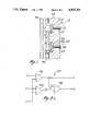
- FIG. 1is a cross-sectional view of the pH sensing electrode and the CO 2 sensing electrode of the present invention
- FIG. 2is a reverse frontal partly fragmentary view of the electrode card
- FIGS. 3a to 3care schematic diagrams showing alternative electrical circuits for generating the signal proportional to the dissolved carbon dioxide gas.
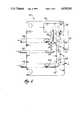
- FIG. 4is a schematic diagram showing the major components of a preferred embodiment of the carbon dioxide gas analysis system of the present invention.
- a preferred embodiment of the inventionis adapted to measure the unbound concentration, or activity, of the single gas, carbon dioxide, and the pH of any of a variety of aqueous fluids.
- FIG. 1illustrates the structure of a pair of sensors employed to measure both the pH of the fluid and the dissolved carbon dioxide gas of the fluid. These electrodes are formed in a substrate 30 and communicate with a measurement flow channel 34 which is formed by the combination of substrate 30 and cover plate 32.
- FIG. 1illustrates pH sensor 10 and CO 2 sensor 20.
- the pH sensor 10includes a wire 17 disposed in and substantially filling a hole 12 in the substrate 30. This wire 17 is preferably made of silver. At one end of the wire, the end opposite the measurement flow chamber 34, wire 17 is coupled to electrical conductor 19 which serves as the electrical connection to pH sensor 10. Conductor 19 may be in the form of a printed circuit conductor which lies upon the opposite surface of substrate 30.
- Electrochemically active layer 15serves to electrochemically couple wire 17 to the electrolyte layer 13. In accordance with the preferred embodiment, electrochemically active layer 15 is formed of silver chloride.
- the remaining portions of pH sensor 10are formed in a shallow well 14 which is preferably concentric about the electrode hole 12.
- the inner layer 13is an electrolyte layer which when hydrated forms an aqueous solution which is buffered against changes in pH due to the changes in the dissolved CO 2 concentration of the fluid.
- this electrolyte layeris formed from the dried residue of an aqueous solution of 2-(n-morpholino) ethanesulfonic acid, 2-(n-morpholino) ethanesulfonic acid-sodium salt (MES) and potassium chloride.
- MES2-(n-morpholino) ethanesulfonic acid-sodium salt
- this electrolyte layeris formed of an aqueous solution containing 0.024 molar 2-(n-morpholino ethanesulfonic acid, 0.024 molar MES, and 5.0 ⁇ 10 -6 molar potassium chloride.
- the outer layer 11is preferably a membrane which has an outer surface exposed to the fluid in measurement channel 34 and an inner surface which covers the electrolyte layer 13. This membrane must be sensitive to the difference in pH between the inner and outer surfaces thereof to form an electrical potential thereacross and water permeable.
- this membrane 11is formed of the dried residue of a solution of polyvinyl chloride, potassium tetrakis (4-chlorophenyl) borate, bis (2-ethyl hexyl) sebacate and tridodecylamine in an organic solvent.
- a solution of polyvinyl chloride, potassium tetrakis (4-chlorophenyl) borate, bis (2-ethyl hexyl) sebacate and tridodecylaminein an organic solvent.
- the ingredientsare provided in following percentages by weight: 1.0% tridodecylamine; 0.6% potassium tetrakis (4-chlorophenyl) borate; 65.6% bis (2-ethyl hexyl) sebacate; and 32.8% polyvinyl chloride.
- the organic solventis preferably tetrahydrofuran (THF).
- THFtetrahydrofuran
- the CO 2 sensor 20is constructed similar to the construction of pH electrode 10.
- a wire 27is disposed in and substantially fills a hole 22 made in the substrate 30.
- a conductor 29 formed on the outer surface of substrate 30serves as the electrical connection to this wire.
- An electrochemically active layer 25serves to electrochemically couple wire 27 to the electrolyte layer 23.
- the wire 27is composed of silver and the electrochemically active layer 25 is composed of silver chloride.
- the CO 2 sensor 20also includes a pair of layers 21 and 23 disposed in shallow well 24. Shallow well 24 is preferably concentric about hole 22.
- the interior layer 23is an electrolyte layer which when hydrated forms an aqueous solution including bicarbonate ions. This layer could be formed of the dried residue of various salts one of which includes bicarbonate. In accordance with the preferred embodiment, this electrolyte layer is formed of the dry residue of an aqueous solution of polyvinyl alcohol, sodium chloride and sodium bicarbonate.
- this electrolyte layeris formed of an aqueous solution of 4% (weight/volume) polyvinyl alcohol (115,000 molecular weight, 100% hydrolyzed), 0.005 molar sodium bicarbonate, and 0.0005 molar sodium chloride.
- the polyvinyl alcoholis employed to control the degree of hydration and stabilize the thickness of this layer upon rehydration. This serves to foster more reproducable sensor performance.
- Other hydrophylic materialsincluding but not limited to water soluble polymers and starches, could be employed to achieve the same results.
- the outer layer 21is preferably a membrane with the outer surface exposed to the fluid in the measurement flow channel 34 and the inner surface completely covering the electrolyte layer 23.
- membrane 21is formed in the same manner as membrane 11. That is, membrane 21 comprises the dry residue of a solution of polyvinyl chloride, potassium tetrakis (4-chlorophenyl) borate, bis (2-ethyl hexyl) sebacate and tridodecylamine in an organic solvent.
- FIG. 2illustrates an embodiment of a sensor assembly 60 including the sensors illustrated in FIG. 1.
- the sensor assembly 60receives a flow of the reference solution via line 46 and sequential flows of either the blood sample or one of two calibrating solutions via line 44.
- the sensor assembly 60also provides a corresponding output of its waste products to a waste collection bag via line 48.
- the sensor assembly 60in a preferred embodiment consists of a structurally rigid rectangular plate or substrate 30 of polyvinylchloride having a rectangular aluminum cover plate 32 adhered to one of its surfaces. Cover plate 32 closes off the flow channels formed in one surface of the substrate 30 and also acts as a heat transfer medium to maintain the fluids flowing through the sensor assembly, and the sensors themselves, at a constant temperature. This may be achieved by measuring the temperature of the plate 32 and employing a suitable heating or cooling element to maintain the temperature of the plate at a constant desired level.
- the rectangular sensor assembly 60is intended to be used with its major surfaces and its major axis in the vertical plane and is so supported.
- the flow line 44passes through the thickness of plate 30 from the side opposite to the plate 32, near the bottom of the plate 30, at an angle (FIG. 2) with respect to the plates, to communicate with measurement flow channel 34 formed in suitable manner (e.g., machined, molded, or etched) in the surface of the plate 30 that abuts the cover plate 32, so that the abutting surface of the plate 32 forms one wall of the measurement flow channel 34.
- measurement flow channel 34turns upward and extends parallel to the one long edge of the plates 30 and 32.
- measurement flow channel 34makes a hair pin (180°) bend inward, away from the edge of the plate, at 36 to form a downwardly extending channel 38 parallel to and spaced from measurement flow channel 34.
- the channel 30makes a 90° turn to join with a short horizontally extending channel 56.
- the waste flow line 48passes through the thickness of the substrate 30 from the side opposite to the cover plate 32 to communicate with the end of the flow channel 56.
- blood samples or calibrating solutionpumped into the electrode assembly via line 44, move along flow channel 34, then around the curve of the channel 36 at the top of the assembly, down the channel 38, and finally horizontally along the channel 56 to the output flow line 48 which carries the used fluids to a waste bag.
- measurement flow channel 34in which the blood and calibrating solutions must flow vertically upward ensures that any microbubbles in the blood or calibrating solution will rise to the space at the top of channel 36 and not interfere with accurate measurements made by the electrodes.
- a reference solutionis introduced to a reference solution chamber 52 formed in the surface of the substrate 30 in the same manner as the other flow channels and similarly covered by the metal plate 32.
- a reference solution flow line 46passes through an inclined hole in reference solution chamber 52.
- the reference solution chamberis connected to the output section 56 of the flow channel through a very thin capillary channel 54 formed in the surface of the plastic substrate 30 in the same manner as the main flow channels.
- the capillary channel 54is straight and substantially shallower and narrower than the main flow channel; its cross section is approximately 0.5 sq. mm.
- Reference fluid pumped into reference solution chamber 52, via a line 46,fills the reference solution chamber 52, and is forced through the capillary channel 54 where it joins the output stream of fluid passing through the main flow channel section and then flows with it to the waste bag.
- the combined influence of its higher density and the capillarity of the capillary channel 54serves to minimize any possibility of calibrating solution or blood passing downward through the capillary section 54 to the reference solution chamber 52 and upsetting the electrochemical measurements
- a blood sample or calibration solutionis introduced into measurement flow channel 34 and passes to the output section 56, it passes over a number of electrodes.
- electrodesinclude ground electrode 40, which is a silver wire staked in a hole in substrate 30, pH sensor electrode 10 and CO 2 sensor electrode 20, constructed as described above. These may also include a number of other electrodes (noted generally by 42) for measuring other electrochemical characteristics of the fluid in the measurement flow channel 34.
- an electrode 50is staked through the thickness of the substrate 30 into the reference solution chamber 56 to act as a reference electrode.
- the reference solutionfills the reference chamber 52 where it contacts a silver wire 50 and is pumped through the capillary channel 54 to join the outlet section 56.
- the reference solutionis essentially a hypertonic solution of potassium chloride, with respect to the blood or the calibrating solutions and accordingly the domain of the reference electrode 50 constitutes a stable potential liquid junction formed between the reference electrode and the blood or calibrating solution, thereby establishing an environment that is independent of the ionic activity of the blood or calibrating solution.
- the reference solutionjoins the main flow channel downstream from the electrodes, after the gas/electrolyte measurements have been made, it does not affect those measurements in any way.
- the reference solutionis of high density and under pumping force must flow upward against gravity to the outlet.
- the pump stops, as for electrode equilibrationthe reference solution remains stationary in the reference solution chamber 52 and the capillary channel 54 and tends not to diffuse into the calibrating solution or blood in the main flow channel.
- the capillary channel 54due to the density gradient, acts as a one way valve allowing pumped reference solution to pass upwardly through the capillary channel but preventing unwanted reverse passage or mixing of the blood or calibrating solution into the reference well.
- FIGS. 3a, 3b and 3cillustrate alternative connections for the measurements made with pH sensor 10 and CO 2 sensor 20.
- FIG. 3aillustrates a simple system without the use of a reference electrode.
- FIG. 3billustrates the use of a reference electrode.
- FIG. 3cillustrates the use of a reference electrode, a multiplexer and an analog-to-digital converter.
- FIG. 3aillustrates the simplest circuit for generating the respective pH signal and the CO 2 signal.
- Differential amplifier 102has its positive input connected to pH sensor 10 and its negative input connected to ground electrode 40.
- differential amplifier 104has its positive input connected to CO 2 sensor 20 and its negative input connected to ground electrode 40.
- the output of differential amplifier 102is the pH signal.
- the output of differential amplifier 102is applied to the negative input of differential amplifier 106.
- the output of differential amplifier 104is a signal proportional to both the dissolved carbon dioxide and the pH of the solution. This signal is applied to the positive input by differential amplifier 106.
- Differential amplifier 106forms a difference between these signals and thus removes the pH dependence of the signal from differential amplifier 104.
- Differential amplifier 106also removes from the CO 2 signal any dependence upon the electrical potential at ground electrode 40. Any of several common types of electrochemical reference electrodes known in the art can be substituted for the ground electrode 40 described herein.
- the output of differential amplifier 106is the difference in electrical potential between the CO 2 sensor 20 and pH sensor 10. Therefore the output of differential amplifier 106 is the desired CO 2 signal.
- FIG. 3billustrates electrical circuit 100' showing the use of reference electrode 50.
- Reference electrode 50is employed to provide a highly stable reference potential relative to ground electrode 40 which may drift or shift potential when the properties of the fluid in chamber 36 changes in order to correct for any electrochemical drift in the signals at the pH sensor 10 and the CO 2 sensor 20.
- Differential amplifiers 102 and 104are connected as illustrated before in FIG. 3a.
- Differential amplifier 108has the signal at reference electrode 50 connected to its positive input and the signal from ground electrode 40 connected to its negative input.
- Differential amplifier 110has the output of differential amplifier 102 connected to its positive input and the output of differential amplifier 108 connected to its negative input. Differential amplifier 110 thus removes any ground potential voltage drift from the pH signal. This ground potential voltage drift is measured by the reference electrode 50.
- differential amplifier 112has the output of differential amplifier 104 connected to its positive input and the output of differential amplifier 108 connected to its negative input.
- the output of differential amplifier 112is the combined carbon dioxide and pH signal with the ground potential drift removed.
- Differential amplifier 106is connected as illustrated in FIG. 3a in order to derive at its output the CO 2 signal dependent only upon the concentration of dissolved carbon dioxide in the fluid.
- FIG. 3cillustrates electrical circuit 100" suitable for use with a digital processing system.
- Differential amplifiers 102, 104 and 108are connected to the electrodes in the manner previously illustrated in FIG. 3b.
- the output of differential amplifier 102is connected to sample and hold circuit 120.
- the output of differential amplifier 104is connected to sample and hold circuit 122 and the output of differential amplifier 108 is connected to sample and hold circuit 124.
- Each sample and hold circuitserves to detect the output of its respective differential amplifier at a particular sample time and to hold that output until the next sample time.
- the output of the sample and hold circuits 120, 122 and 124are separately applied to multiplexer 126.
- Multiplexer 126serves to connect the output of one of the sample and hold circuits 120, 122 or 124 to analog-to-digital converter 128.
- Analog-to-digital converter 128generates a digital signal corresponding to the magnitude of the analog signal connected thereto. Therefore the output 130 of analog-to-digital converter 128 is a series of digital numbers corresponding to respective measurements of the electrical potential at pH sensor 10, CO 2 sensor 20 and reference electrode 50.
- the embodiment illustrated in FIG. 3c of electrical circuit 100"is employed with a digital processing circuit, such as a microprocessor, which performs the subtraction operation in a digital domain similar to the subtraction operations performed by differential amplifiers 106, 110 and 112.
- the overall system generally indicated at 200incorporates a microprocessor to control measurement and display of the dissolved carbon dioxide.
- Blood samples to be analyzed by the systemare introduced through a conduit 234. These blood samples are preferably derived on a periodic basis from an extracorporeal blood flow circuit connected to a patient during open heart surgery. The nature of this extracorporeal circuit and the manner in which blood samples may be introduced into the analysis system of the present invention is disclosed in co-pending patent application Ser. No. 713,435, now abandoned, entitled “Apparatus For Chemical Measurement of Blood Characteristics," assigned to the assignee of the present invention and the disclosure of that co-pending application is incorporated herein by reference.
- blood samplesmay be introduced into the flow line 234 through other automatic means, or manually, as by syringe.
- the blood samplesmay be introduced as discrete samples, as described above.
- the systemincorporates two prepackaged containers 231 and 232 each containing calibrating aqueous solutions having known values of the parameters to be measured by the system.
- the two calibrating solutionshave different known values of each of the measured parameters to allow the system to be calibrated on a 2-point basis.
- the solution contained within the bag 231will be termed Calibrating Solution A and the solution contained within the bag 232 will be referred to as Calibrating Solution B.
- Each of the bags 231 and 232contains a sufficient quantity of its calibrating solution to allow the system to be calibrated a substantial number of times before the cartridge 250 containing the containers must be replaced.
- the container 231is connected to a first input of a 3-position valve 233 and the container 232 for calibration solution B is connected to a second input of the 3-position valve.
- the blood sample flow inlet 234is connected to a third input of the three-position valve.
- the valve 233is adapted to connect the input flow from either container 231, container 232 or inlet 234 to an output flow line 44, depending upon the position of the valve.
- the flow line 44extends to the input of the sensor assembly 60.
- the position of valve 233is controlled by microprocessor 210 via valve driver 221.
- the systemincludes a third container 241 for a reference solution.
- the container 241is connected to the sensor assembly 60 by a flow line 46.
- Pump 243causes the reference solution in container 241 to flow to sensor assembly 60.
- the systemfurther includes a fourth container 242 for waste, which receives the blood samples, the calibrating solutions and the reference solution after they have passed through the sensor assembly 60, via a flexible conduit 48 that has input from the plate 30.
- Pump 244causes flow from the source selected by valve 233, through the sensor assembly 60 into waste container 242.
- Both pumps 243 and 244are preferably sections of flexible walled tubing that pass through a peristaltic pump. Such a pump compresses and strokes the flexible sections of the flow lines 46 and 48 to induce a pressured flow. Pump 244 creates a negative pressure on the waste products in flow line 48 so as to draw fluids in the flow line 44 through passages in the sensor assembly 60. This arrangement, as opposed to the alternative of inducing positive pressure on the blood and calibrating solutions to force them through the sensor assembly 60, avoids the imposition of unnecessary and possibly traumatic mechanical forces on the blood sample and minimizes possibilities of leaks in the electrode assembly.
- the system as heretofore described in a preferred embodiment of the present inventionis contained in a disposable cartridge 250.
- a cartridge of a similar typeis set forth in detail in the co-pending patent application referred to above.
- the cartridge 250contains sufficient quantities of the calibrating solutions and the reference solution to perform analysis of a number of samples of blood.
- This cartridge 250also includes the valve 233, the electrode assembly 30 and waste container 242. After use, the cartridge 250 is intended to be discarded and replaced with another cartridge 250.
- the sensor assembly 60has a number of edge connectors in a bank which allow it to be plugged into a female matching connector so that the electrodes formed on the sensor assembly 60 may be connected to microprocessor 210.
- the microprocessor 210is connected to the valve 233 via valve driver 221 and to the peristaltic pumps 243 and 244 via pump driver 223.
- Microprocessor 210controls the position of the valve 233 and the energization of the pumps 243 and 244 to cause sequences of blood samples and calibrating solutions to be passed through the electrode assembly.
- the sensors forming part of the assemblymake measurements of the parameters of the sample and microprocessor 210 stores these electrical values.
- microprocessor 210Based upon measurements made during the passage of the calibration solutions through the electrode assembly, and the known values of the measured parameters contained within the calibrating solution, microprocessor 210 effectively creates a calibration curve for each of the measured parameters so that when a blood sample is passed through the sensor assembly 60 the measurements made by the sensors can be used to derive accurate measurements of the parameters of interest. These parameters are stored, the corresponding quantities calculated and displayed by microprocessor 210 and displayed via display 214 and/or printer 213.
- the microprocessor 210is preferably suitably programmed to perform measurement, calculation, storage and control functions, all as described in co-pending application referred to previously.
- the valve 233is controlled to direct one of the calibration solutions into the sensor assembly so it entirely fills the flow channel and is void-free.
- the pumpis then stopped for a period (e.g., 30 minutes) during which the electrodes are allowed to stabilize in the electrode solution.
- This stabilizationincludes the rehydration of the dried electrolyte layer 13 of pH sensor 10 and the dried electrolyte layer 23 of CO 2 sensor 20. This rehydration is required for proper operation of these sensors and thus the stabilization period prior to first use is necessary.
- a predetermined quantity of new calibration solution Ais pumped into and through the sensor assembly 60 and during a dwell period (e.g., 90-second dwell) measurements of the various potentials and currents are made and processed by the microprocessor 210.
- a predetermined quantity of calibration solution Bis pumped into and through the sensor assembly 60 while, during a like dwell, similar measurements are made.
- the blood sample from inlet 234is then pumped into the sensor assembly 60 while analogous measurements are made and, based on the measurements of the blood sample and the stored measurements, microprocessor 210, with suitable allowance permitted by 2-point calibration, generates the gas/electrolyte values characteristic for the particular blood sample.
- This processmay be repeated a number of times, either automatically or manually using discrete blood samples under operator control, all within the operating theater or at bedside, to derive quantitative parameters for any of a series of blood samples over a period of time, until the solutions have been depleted, at which time the spent cartridge can be discarded and replaced with a fresh one. It is particularly advantageous for these disposable cartridges to employ pH and CO 2 sensors which include dry stored electrolyte layers that are rehydrated prior to first use. This enhances the ease of storage of these cartridges because the electrolyte layers need not be continuously hydrated during storage.
Landscapes
- Health & Medical Sciences (AREA)
- Life Sciences & Earth Sciences (AREA)
- Chemical & Material Sciences (AREA)
- Engineering & Computer Science (AREA)
- Physics & Mathematics (AREA)
- Biomedical Technology (AREA)
- General Physics & Mathematics (AREA)
- Hematology (AREA)
- Biochemistry (AREA)
- General Health & Medical Sciences (AREA)
- Analytical Chemistry (AREA)
- Immunology (AREA)
- Pathology (AREA)
- Molecular Biology (AREA)
- Electrochemistry (AREA)
- Chemical Kinetics & Catalysis (AREA)
- Ecology (AREA)
- Biophysics (AREA)
- Urology & Nephrology (AREA)
- Food Science & Technology (AREA)
- Medicinal Chemistry (AREA)
- Investigating Or Analysing Biological Materials (AREA)
Abstract
Description
Claims (16)
Priority Applications (1)
| Application Number | Priority Date | Filing Date | Title |
|---|---|---|---|
| US07/126,438US4818361A (en) | 1986-12-10 | 1987-11-30 | Combined pH and dissolved carbon dioxide gas sensor |
Applications Claiming Priority (2)
| Application Number | Priority Date | Filing Date | Title |
|---|---|---|---|
| US94052786A | 1986-12-10 | 1986-12-10 | |
| US07/126,438US4818361A (en) | 1986-12-10 | 1987-11-30 | Combined pH and dissolved carbon dioxide gas sensor |
Related Parent Applications (1)
| Application Number | Title | Priority Date | Filing Date |
|---|---|---|---|
| US94052786AContinuation-In-Part | 1986-12-10 | 1986-12-10 |
Publications (1)
| Publication Number | Publication Date |
|---|---|
| US4818361Atrue US4818361A (en) | 1989-04-04 |
Family
ID=26824649
Family Applications (1)
| Application Number | Title | Priority Date | Filing Date |
|---|---|---|---|
| US07/126,438Expired - Fee RelatedUS4818361A (en) | 1986-12-10 | 1987-11-30 | Combined pH and dissolved carbon dioxide gas sensor |
Country Status (1)
| Country | Link |
|---|---|
| US (1) | US4818361A (en) |
Cited By (44)
| Publication number | Priority date | Publication date | Assignee | Title |
|---|---|---|---|---|
| US4925544A (en)* | 1987-05-15 | 1990-05-15 | National Research Development Corporation | Electrochemical sensor with solid phase electrolyte |
| USH949H (en) | 1988-03-16 | 1991-08-06 | Fuji Photo Film Co., Ltd. | Device for measuring ionic activity |
| US5078854A (en)* | 1990-01-22 | 1992-01-07 | Mallinckrodt Sensor Systems, Inc. | Polarographic chemical sensor with external reference electrode |
| US5110441A (en)* | 1989-12-14 | 1992-05-05 | Monsanto Company | Solid state ph sensor |
| US5165292A (en)* | 1985-12-09 | 1992-11-24 | Ottosensors Corporation | Channel Device and tube connection and their fabrication procedures |
| WO1993000582A1 (en)* | 1991-06-26 | 1993-01-07 | Ppg Industries, Inc. | Integrated circuit hydrated sensor apparatus |
| WO1993009433A1 (en)* | 1991-11-08 | 1993-05-13 | Via Medical Corporation | Electrochemical measurement system having interference reduction circuit |
| US5271820A (en)* | 1992-06-19 | 1993-12-21 | Monsanto Company | Solid state pH sensor |
| US5336388A (en)* | 1991-12-26 | 1994-08-09 | Ppg Industries, Inc. | Analyte and pH measuring sensor assembly and method |
| US5342498A (en)* | 1991-06-26 | 1994-08-30 | Graves Jeffrey A | Electronic wiring substrate |
| US5405510A (en)* | 1992-05-18 | 1995-04-11 | Ppg Industries, Inc. | Portable analyte measuring system for multiple fluid samples |
| EP0505530A4 (en)* | 1990-09-13 | 1995-05-03 | David K Wong | |
| US5421981A (en)* | 1991-06-26 | 1995-06-06 | Ppg Industries, Inc. | Electrochemical sensor storage device |
| EP0609198A3 (en)* | 1993-01-27 | 1996-07-03 | Avl Medical Instr Ag | Electrode arrangement. |
| US5554272A (en)* | 1995-08-10 | 1996-09-10 | Ciba Corning Diagnostics Corp. | Planar bicarbonate sensor |
| WO1997043634A1 (en)* | 1996-05-16 | 1997-11-20 | Sendx Medical, Inc. | Sensors with subminiature through holes, and method for fabricating such sensors |
| WO1998040731A1 (en)* | 1997-03-12 | 1998-09-17 | Sendx Medical, Inc. | Method for fabricating wiring substrate with subminiature thru-holes |
| US5916425A (en)* | 1996-05-16 | 1999-06-29 | Sendx Medical, Inc. | Electronic wiring substrate with subminiature thru-holes |
| US6022463A (en)* | 1996-05-16 | 2000-02-08 | Sendx Medical, Inc. | Sensors with subminiature through holes |
| US6123820A (en)* | 1998-06-05 | 2000-09-26 | Grupo Ch-Werfen, S.A. | Sensor cartridges |
| US6146510A (en)* | 1996-05-16 | 2000-11-14 | Sendx Medical, Inc. | Sensor cartridge for a fluid analyte analyzer |
| US6355158B1 (en) | 1999-01-07 | 2002-03-12 | Bayer Corporation | Method of measuring pH |
| WO2001042473A3 (en)* | 1999-12-10 | 2002-05-30 | Instrumentation Lab Co | Device and method for accelerated hydration of dry chemical sensors |
| US20030029722A1 (en)* | 2001-03-07 | 2003-02-13 | Instrumentation Laboratory Company | Reference electrode |
| US20030201192A1 (en)* | 2002-03-13 | 2003-10-30 | The Charles Stark Draper Laboratory, Inc. | Disposable, self-administered electrolyte test |
| US20030209451A1 (en)* | 2002-03-13 | 2003-11-13 | The Charles Stark Draper Laboratory, Inc. | Microfluidic ion-selective electrode sensor system |
| EP1164372A3 (en)* | 2000-06-12 | 2004-05-19 | i-SENS, INC. | Microchip-based carbon dioxide gas sensor |
| US20040154933A1 (en)* | 2003-02-11 | 2004-08-12 | Instrumentation Laboratory Company | Polymeric membranes for use in electrochemical sensors |
| US6794877B2 (en) | 2002-07-31 | 2004-09-21 | International Technidyne Corporation | Apparatus and method for analytical determinations |
| US20040209371A1 (en)* | 2002-12-11 | 2004-10-21 | Conlon Dennis Robert | Multi-analyte reference solutions |
| US20040256227A1 (en)* | 2003-02-11 | 2004-12-23 | Jungwon Shin | Electrochemical urea sensors and methods of making the same |
| WO2007022473A1 (en)* | 2005-08-19 | 2007-02-22 | Honeywell International Inc. | Electrochemical chlorine dioxide sensor and method for detecting said chlorine dioxide |
| US20100030137A1 (en)* | 2005-02-14 | 2010-02-04 | Optiscan Biomedical Corporation | Apparatus and methods for analyzing body fluid samples |
| US20100155239A1 (en)* | 2008-12-22 | 2010-06-24 | Radiometer Medical Aps | Planar sensor |
| US20100200400A1 (en)* | 2009-02-06 | 2010-08-12 | Commissariat A L'energie Atomique | Embedded bodily fluid analysis device |
| US8607612B2 (en) | 2011-05-27 | 2013-12-17 | Lightship Medical Limited | Sensor calibration |
| US9423393B2 (en) | 2002-06-28 | 2016-08-23 | International Technidyne Corporation | Analytical test cartridge; and, methods |
| US20170089882A1 (en)* | 2014-01-22 | 2017-03-30 | Molecular Devices, Llc | Replaceable ground electrode for electrophysiology, electrode rejuvenating apparatus, and related methods and systems |
| US10475529B2 (en) | 2011-07-19 | 2019-11-12 | Optiscan Biomedical Corporation | Method and apparatus for analyte measurements using calibration sets |
| WO2019232007A1 (en)* | 2018-05-31 | 2019-12-05 | Hach Company | Ph measurement of an aqueous sample |
| US20210123875A1 (en)* | 2015-01-20 | 2021-04-29 | The Regents Of The University Of Michigan | Multi-functional water quality sensor |
| US20230213469A1 (en)* | 2022-01-05 | 2023-07-06 | Hach Company | Differential probe with low-slope component |
| WO2024059402A3 (en)* | 2022-09-12 | 2024-05-02 | Siemens Healthcare Diagnostics Inc. | Methods of detecting blood clots/deposits on blood gas analyzer sensors |
| US12436160B2 (en) | 2022-08-19 | 2025-10-07 | Siemens Healthcare Diagnostics Inc. | Method of detecting an obstruction in a fluid analyzer |
Citations (3)
| Publication number | Priority date | Publication date | Assignee | Title |
|---|---|---|---|---|
| US3896020A (en)* | 1974-08-02 | 1975-07-22 | Gen Electric | Carbon dioxide and pH sensor |
| US4225410A (en)* | 1978-12-04 | 1980-09-30 | Technicon Instruments Corporation | Integrated array of electrochemical sensors |
| US4734184A (en)* | 1985-08-29 | 1988-03-29 | Diamond Sensor Systems, Inc. | Self-activating hydratable solid-state electrode apparatus |
- 1987
- 1987-11-30USUS07/126,438patent/US4818361A/ennot_activeExpired - Fee Related
Patent Citations (3)
| Publication number | Priority date | Publication date | Assignee | Title |
|---|---|---|---|---|
| US3896020A (en)* | 1974-08-02 | 1975-07-22 | Gen Electric | Carbon dioxide and pH sensor |
| US4225410A (en)* | 1978-12-04 | 1980-09-30 | Technicon Instruments Corporation | Integrated array of electrochemical sensors |
| US4734184A (en)* | 1985-08-29 | 1988-03-29 | Diamond Sensor Systems, Inc. | Self-activating hydratable solid-state electrode apparatus |
Non-Patent Citations (2)
| Title |
|---|
| D. Ammann et al, Ion Selective Electrode Reviews, vol. 5, p. 38, (1983).* |
| D. Ammann et al, Ion-Selective Electrode Reviews, vol. 5, p. 38, (1983). |
Cited By (68)
| Publication number | Priority date | Publication date | Assignee | Title |
|---|---|---|---|---|
| US5165292A (en)* | 1985-12-09 | 1992-11-24 | Ottosensors Corporation | Channel Device and tube connection and their fabrication procedures |
| US4925544A (en)* | 1987-05-15 | 1990-05-15 | National Research Development Corporation | Electrochemical sensor with solid phase electrolyte |
| USH949H (en) | 1988-03-16 | 1991-08-06 | Fuji Photo Film Co., Ltd. | Device for measuring ionic activity |
| AU639276B2 (en)* | 1989-12-14 | 1993-07-22 | Monsanto Company | Solid state ph sensor |
| US5110441A (en)* | 1989-12-14 | 1992-05-05 | Monsanto Company | Solid state ph sensor |
| US5078854A (en)* | 1990-01-22 | 1992-01-07 | Mallinckrodt Sensor Systems, Inc. | Polarographic chemical sensor with external reference electrode |
| EP0505530A4 (en)* | 1990-09-13 | 1995-05-03 | David K Wong | |
| US5338435A (en)* | 1991-06-26 | 1994-08-16 | Ppg Industries, Inc. | Integrated circuit hydrated sensor apparatus |
| US5342498A (en)* | 1991-06-26 | 1994-08-30 | Graves Jeffrey A | Electronic wiring substrate |
| US5421981A (en)* | 1991-06-26 | 1995-06-06 | Ppg Industries, Inc. | Electrochemical sensor storage device |
| WO1993000582A1 (en)* | 1991-06-26 | 1993-01-07 | Ppg Industries, Inc. | Integrated circuit hydrated sensor apparatus |
| WO1993009433A1 (en)* | 1991-11-08 | 1993-05-13 | Via Medical Corporation | Electrochemical measurement system having interference reduction circuit |
| US5336388A (en)* | 1991-12-26 | 1994-08-09 | Ppg Industries, Inc. | Analyte and pH measuring sensor assembly and method |
| EP0619019A4 (en)* | 1991-12-26 | 1996-09-11 | Ppg Industries Inc | Analyte and ph measuring sensor assembly and method. |
| US5405510A (en)* | 1992-05-18 | 1995-04-11 | Ppg Industries, Inc. | Portable analyte measuring system for multiple fluid samples |
| US5271820A (en)* | 1992-06-19 | 1993-12-21 | Monsanto Company | Solid state pH sensor |
| EP0609198A3 (en)* | 1993-01-27 | 1996-07-03 | Avl Medical Instr Ag | Electrode arrangement. |
| AU699262B2 (en)* | 1995-08-10 | 1998-11-26 | Chiron Diagnostics Corporation | Planar bicarbonate sensor |
| US5554272A (en)* | 1995-08-10 | 1996-09-10 | Ciba Corning Diagnostics Corp. | Planar bicarbonate sensor |
| EP0759551A3 (en)* | 1995-08-10 | 1998-03-04 | Ciba Corning Diagnostics Corp. | Planar bicarbonate sensor |
| WO1997043634A1 (en)* | 1996-05-16 | 1997-11-20 | Sendx Medical, Inc. | Sensors with subminiature through holes, and method for fabricating such sensors |
| US5916425A (en)* | 1996-05-16 | 1999-06-29 | Sendx Medical, Inc. | Electronic wiring substrate with subminiature thru-holes |
| US6022463A (en)* | 1996-05-16 | 2000-02-08 | Sendx Medical, Inc. | Sensors with subminiature through holes |
| US6146510A (en)* | 1996-05-16 | 2000-11-14 | Sendx Medical, Inc. | Sensor cartridge for a fluid analyte analyzer |
| WO1998040731A1 (en)* | 1997-03-12 | 1998-09-17 | Sendx Medical, Inc. | Method for fabricating wiring substrate with subminiature thru-holes |
| US6123820A (en)* | 1998-06-05 | 2000-09-26 | Grupo Ch-Werfen, S.A. | Sensor cartridges |
| US6355158B1 (en) | 1999-01-07 | 2002-03-12 | Bayer Corporation | Method of measuring pH |
| WO2001042473A3 (en)* | 1999-12-10 | 2002-05-30 | Instrumentation Lab Co | Device and method for accelerated hydration of dry chemical sensors |
| EP1164372A3 (en)* | 2000-06-12 | 2004-05-19 | i-SENS, INC. | Microchip-based carbon dioxide gas sensor |
| US20030029722A1 (en)* | 2001-03-07 | 2003-02-13 | Instrumentation Laboratory Company | Reference electrode |
| US6896793B2 (en) | 2001-03-07 | 2005-05-24 | Instrumentation Laboratory Company | Liquid junction reference electrode and methods of use thereof |
| US20030201192A1 (en)* | 2002-03-13 | 2003-10-30 | The Charles Stark Draper Laboratory, Inc. | Disposable, self-administered electrolyte test |
| US7101472B2 (en) | 2002-03-13 | 2006-09-05 | The Charles Stark Draper Laboratory, Inc. | Microfluidic ion-selective electrode sensor system |
| US7407570B2 (en) | 2002-03-13 | 2008-08-05 | The Charles Stark Draper Laboratory, Inc. | Disposable, self-administered electrolyte test |
| US20030209451A1 (en)* | 2002-03-13 | 2003-11-13 | The Charles Stark Draper Laboratory, Inc. | Microfluidic ion-selective electrode sensor system |
| US9423393B2 (en) | 2002-06-28 | 2016-08-23 | International Technidyne Corporation | Analytical test cartridge; and, methods |
| US6794877B2 (en) | 2002-07-31 | 2004-09-21 | International Technidyne Corporation | Apparatus and method for analytical determinations |
| US20040209371A1 (en)* | 2002-12-11 | 2004-10-21 | Conlon Dennis Robert | Multi-analyte reference solutions |
| US7422903B2 (en) | 2002-12-11 | 2008-09-09 | Instrumentation Laboratory Company | Multi-analyte reference solutions |
| US20090215181A1 (en)* | 2002-12-11 | 2009-08-27 | Dennis Robert Conlon | Multi-Analyte Reference Solutions |
| US7732210B2 (en) | 2002-12-11 | 2010-06-08 | Instrumentation Laboratory Company | Multi-analyte reference solutions |
| US20040256227A1 (en)* | 2003-02-11 | 2004-12-23 | Jungwon Shin | Electrochemical urea sensors and methods of making the same |
| US20040154933A1 (en)* | 2003-02-11 | 2004-08-12 | Instrumentation Laboratory Company | Polymeric membranes for use in electrochemical sensors |
| US20100030137A1 (en)* | 2005-02-14 | 2010-02-04 | Optiscan Biomedical Corporation | Apparatus and methods for analyzing body fluid samples |
| EP2138097A3 (en)* | 2005-02-14 | 2010-06-23 | Optiscan Biomedical Corporation | Apparatus and methods for analyzing body fluid samples |
| WO2007022473A1 (en)* | 2005-08-19 | 2007-02-22 | Honeywell International Inc. | Electrochemical chlorine dioxide sensor and method for detecting said chlorine dioxide |
| US20070045128A1 (en)* | 2005-08-19 | 2007-03-01 | Honeywell International Inc. | Chlorine dioxide sensor |
| GB2443134A (en)* | 2005-08-19 | 2008-04-23 | Honeywell Int Inc | Electrochemical chlorine dioxide sensor and method for detecting said chlorine dioxide |
| CN102326072B (en)* | 2008-12-22 | 2014-09-10 | 雷迪奥米特医学公司 | flat panel sensor |
| US10060906B2 (en) | 2008-12-22 | 2018-08-28 | Radiometer Medical Aps | Planar sensor |
| CN102326072A (en)* | 2008-12-22 | 2012-01-18 | 雷迪奥米特医学公司 | flat panel sensor |
| WO2010072223A1 (en) | 2008-12-22 | 2010-07-01 | Radiometer Medical Aps | Planar sensor |
| US20100155239A1 (en)* | 2008-12-22 | 2010-06-24 | Radiometer Medical Aps | Planar sensor |
| CN104215671B (en)* | 2008-12-22 | 2017-04-12 | 雷迪奥米特医学公司 | Planar sensor |
| US20100200400A1 (en)* | 2009-02-06 | 2010-08-12 | Commissariat A L'energie Atomique | Embedded bodily fluid analysis device |
| US8607612B2 (en) | 2011-05-27 | 2013-12-17 | Lightship Medical Limited | Sensor calibration |
| US10475529B2 (en) | 2011-07-19 | 2019-11-12 | Optiscan Biomedical Corporation | Method and apparatus for analyte measurements using calibration sets |
| US20170089882A1 (en)* | 2014-01-22 | 2017-03-30 | Molecular Devices, Llc | Replaceable ground electrode for electrophysiology, electrode rejuvenating apparatus, and related methods and systems |
| US11067563B2 (en)* | 2014-01-22 | 2021-07-20 | Molecular Devices, Llc | Replaceable ground electrode for electrophysiology, electrode rejuvenating apparatus, and related methods and systems |
| US12085559B2 (en) | 2014-01-22 | 2024-09-10 | Molecular Devices, Llc | Replaceable ground electrode for electrophysiology, electrode rejuvenating apparatus, and related methods and systems |
| US20210123875A1 (en)* | 2015-01-20 | 2021-04-29 | The Regents Of The University Of Michigan | Multi-functional water quality sensor |
| WO2019232007A1 (en)* | 2018-05-31 | 2019-12-05 | Hach Company | Ph measurement of an aqueous sample |
| CN112119300A (en)* | 2018-05-31 | 2020-12-22 | 哈希公司 | pH measurement of water samples |
| US11169112B2 (en) | 2018-05-31 | 2021-11-09 | Hach Company | pH measurement of an aqueous sample |
| US20230213469A1 (en)* | 2022-01-05 | 2023-07-06 | Hach Company | Differential probe with low-slope component |
| US11959870B2 (en)* | 2022-01-05 | 2024-04-16 | Hach Company | Differential probe with low-slope component |
| US12436160B2 (en) | 2022-08-19 | 2025-10-07 | Siemens Healthcare Diagnostics Inc. | Method of detecting an obstruction in a fluid analyzer |
| WO2024059402A3 (en)* | 2022-09-12 | 2024-05-02 | Siemens Healthcare Diagnostics Inc. | Methods of detecting blood clots/deposits on blood gas analyzer sensors |
Similar Documents
| Publication | Publication Date | Title |
|---|---|---|
| US4818361A (en) | Combined pH and dissolved carbon dioxide gas sensor | |
| US4734184A (en) | Self-activating hydratable solid-state electrode apparatus | |
| US4786394A (en) | Apparatus for chemical measurement of blood characteristics | |
| US4871439A (en) | Disposable self-calibratable electrode package | |
| US4841974A (en) | Apparatus and method for the examination of a liquid medium | |
| US4005002A (en) | Apparatus for measuring substrate concentrations | |
| US5747666A (en) | Point-of-care analyzer module | |
| EP0958499B1 (en) | Method for calibrating sensors used in diagnostic testing | |
| US4654127A (en) | Self-calibrating single-use sensing device for clinical chemistry and method of use | |
| US5330634A (en) | Calibration solutions useful for analyses of biological fluids and methods employing same | |
| US5004583A (en) | Universal sensor cartridge for use with a universal analyzer for sensing components in a multicomponent fluid | |
| CA1046795A (en) | Fluid sample analysis system | |
| EP0179129B1 (en) | Self-calibrating single-use sensing device for clinical chemistry analyzer | |
| JPS62119451A (en) | Analyzer | |
| JP2004525369A (en) | Reference electrode | |
| EP0226593B1 (en) | Apparatus for chemical measurement of blood characteristics | |
| JP2003516549A (en) | Device and method for enhanced hydration of dry chemical sensors | |
| Adams et al. | Determination of the blood-gas factor of the oxygen electrode using a new tonometer | |
| WO1994019683A1 (en) | Disposable electrochemical measurement cartridge | |
| US3658679A (en) | System for determining the hydrogen ion concentration of flowing liquids | |
| US4129478A (en) | Method for measuring substrate concentrations | |
| US5207087A (en) | Sensor calibrator and test apparatus | |
| Sibbald et al. | Online patient-monitoring system for the simultaneous analysis of blood K+, Ca2+, Na+ and pH using a quadruple-function ChemFET integrated-circuit sensor | |
| US3661010A (en) | Fluid sample analyzing apparatus | |
| US5710371A (en) | Container for calibrating fluids, and device and method for measuring parameters of a sample of fluid, and oxygen electrode therefor |
Legal Events
| Date | Code | Title | Description |
|---|---|---|---|
| AS | Assignment | Owner name:DIAMOND SENSOR SYSTEMS, 1230 EISENHOWER PLACE, ANN Free format text:ASSIGNMENT OF ASSIGNORS INTEREST.;ASSIGNOR:BURGESS, BRUCE;REEL/FRAME:004841/0556 Effective date:19871130 Owner name:DIAMOND SENSOR SYSTEMS, A CORP. OF DE.,MICHIGAN Free format text:ASSIGNMENT OF ASSIGNORS INTEREST;ASSIGNOR:BURGESS, BRUCE;REEL/FRAME:004841/0556 Effective date:19871130 | |
| AS | Assignment | Owner name:DIAMOND SENSOR SYSTEMS, 1880 EISENHOWER PLACE, ANN Free format text:ASSIGNMENT OF ASSIGNORS INTEREST.;ASSIGNOR:MARTIN, GLENN B.;REEL/FRAME:004824/0179 Effective date:19871203 Owner name:DIAMOND SENSOR SYSTEMS, A CORP OF DE,MICHIGAN Free format text:ASSIGNMENT OF ASSIGNORS INTEREST;ASSIGNOR:MARTIN, GLENN B.;REEL/FRAME:004824/0179 Effective date:19871203 | |
| AS | Assignment | Owner name:MALLINCKRODT SENSOR SYSTEMS, INC., Free format text:ASSIGNMENT OF ASSIGNORS INTEREST. FILE NOVEMBER 9, 1988;ASSIGNOR:DIAMOND ELECTRO-TECH INC.,;REEL/FRAME:004989/0273 Effective date:19881109 | |
| AS | Assignment | Owner name:MALLINCKRODT MEDICAL, INC., 675 MCDONNELL BOULEVAR Free format text:ASSIGNMENT OF ASSIGNORS INTEREST.;ASSIGNOR:MALLINCKRODT, INC., A CORP. OF DE;REEL/FRAME:005635/0379 Effective date:19910227 | |
| FEPP | Fee payment procedure | Free format text:PAYOR NUMBER ASSIGNED (ORIGINAL EVENT CODE: ASPN); ENTITY STATUS OF PATENT OWNER: LARGE ENTITY | |
| FPAY | Fee payment | Year of fee payment:4 | |
| FEPP | Fee payment procedure | Free format text:PAYOR NUMBER ASSIGNED (ORIGINAL EVENT CODE: ASPN); ENTITY STATUS OF PATENT OWNER: LARGE ENTITY Free format text:PAYER NUMBER DE-ASSIGNED (ORIGINAL EVENT CODE: RMPN); ENTITY STATUS OF PATENT OWNER: LARGE ENTITY | |
| FPAY | Fee payment | Year of fee payment:8 | |
| AS | Assignment | Owner name:MALLINCKRODT SENSOR SYSTEMS, INC., MICHIGAN Free format text:ASSIGNMENT OF ASSIGNORS INTEREST;ASSIGNOR:MALLINCKRODT MEDICAL, INC.;REEL/FRAME:008048/0732 Effective date:19960930 | |
| REMI | Maintenance fee reminder mailed | ||
| LAPS | Lapse for failure to pay maintenance fees | ||
| FP | Lapsed due to failure to pay maintenance fee | Effective date:20010404 | |
| STCH | Information on status: patent discontinuation | Free format text:PATENT EXPIRED DUE TO NONPAYMENT OF MAINTENANCE FEES UNDER 37 CFR 1.362 |