US4818186A - Drive mechanism for disposable fluid infusion pumping cassette - Google Patents
Drive mechanism for disposable fluid infusion pumping cassetteDownload PDFInfo
- Publication number
- US4818186A US4818186AUS07/045,959US4595987AUS4818186AUS 4818186 AUS4818186 AUS 4818186AUS 4595987 AUS4595987 AUS 4595987AUS 4818186 AUS4818186 AUS 4818186A
- Authority
- US
- United States
- Prior art keywords
- driver
- cassette
- cam
- recited
- fluid
- Prior art date
- Legal status (The legal status is an assumption and is not a legal conclusion. Google has not performed a legal analysis and makes no representation as to the accuracy of the status listed.)
- Expired - Lifetime
Links
- 239000012530fluidSubstances0.000titleclaimsabstractdescription135
- 238000005086pumpingMethods0.000titleclaimsabstractdescription115
- 238000001802infusionMethods0.000titleabstractdescription8
- 230000007246mechanismEffects0.000titledescription9
- 238000001514detection methodMethods0.000claimsdescription38
- 230000003287optical effectEffects0.000claimsdescription17
- 238000012544monitoring processMethods0.000claimsdescription5
- 230000000712assemblyEffects0.000claimsdescription3
- 238000000429assemblyMethods0.000claimsdescription3
- 239000007788liquidSubstances0.000description30
- 230000036772blood pressureEffects0.000description10
- 230000005484gravityEffects0.000description7
- 230000006870functionEffects0.000description5
- 230000002093peripheral effectEffects0.000description5
- 238000010998test methodMethods0.000description5
- 230000005540biological transmissionEffects0.000description4
- 238000006073displacement reactionMethods0.000description4
- 238000012360testing methodMethods0.000description4
- 238000000034methodMethods0.000description3
- 230000002596correlated effectEffects0.000description2
- 230000007423decreaseEffects0.000description2
- 239000003814drugSubstances0.000description2
- 229940079593drugDrugs0.000description2
- 239000004033plasticSubstances0.000description2
- 239000004417polycarbonateSubstances0.000description2
- 229920000515polycarbonatePolymers0.000description2
- 230000001360synchronised effectEffects0.000description2
- FAPWRFPIFSIZLT-UHFFFAOYSA-MSodium chlorideChemical compound[Na+].[Cl-]FAPWRFPIFSIZLT-UHFFFAOYSA-M0.000description1
- 238000004026adhesive bondingMethods0.000description1
- 230000002238attenuated effectEffects0.000description1
- 238000010276constructionMethods0.000description1
- 230000001276controlling effectEffects0.000description1
- 230000000875corresponding effectEffects0.000description1
- 230000008878couplingEffects0.000description1
- 238000010168coupling processMethods0.000description1
- 238000005859coupling reactionMethods0.000description1
- 239000003085diluting agentSubstances0.000description1
- 238000001361intraarterial administrationMethods0.000description1
- 238000001990intravenous administrationMethods0.000description1
- 230000007257malfunctionEffects0.000description1
- 239000000463materialSubstances0.000description1
- 238000005259measurementMethods0.000description1
- 239000012528membraneSubstances0.000description1
- 239000002184metalSubstances0.000description1
- 239000000203mixtureSubstances0.000description1
- 238000012806monitoring deviceMethods0.000description1
- 238000010926purgeMethods0.000description1
- 230000001105regulatory effectEffects0.000description1
- 238000011144upstream manufacturingMethods0.000description1
- 238000003466weldingMethods0.000description1
Images


Classifications
- A—HUMAN NECESSITIES
- A61—MEDICAL OR VETERINARY SCIENCE; HYGIENE
- A61M—DEVICES FOR INTRODUCING MEDIA INTO, OR ONTO, THE BODY; DEVICES FOR TRANSDUCING BODY MEDIA OR FOR TAKING MEDIA FROM THE BODY; DEVICES FOR PRODUCING OR ENDING SLEEP OR STUPOR
- A61M5/00—Devices for bringing media into the body in a subcutaneous, intra-vascular or intramuscular way; Accessories therefor, e.g. filling or cleaning devices, arm-rests
- A61M5/36—Devices for bringing media into the body in a subcutaneous, intra-vascular or intramuscular way; Accessories therefor, e.g. filling or cleaning devices, arm-rests with means for eliminating or preventing injection or infusion of air into body
- A61M5/365—Air detectors
- A—HUMAN NECESSITIES
- A61—MEDICAL OR VETERINARY SCIENCE; HYGIENE
- A61M—DEVICES FOR INTRODUCING MEDIA INTO, OR ONTO, THE BODY; DEVICES FOR TRANSDUCING BODY MEDIA OR FOR TAKING MEDIA FROM THE BODY; DEVICES FOR PRODUCING OR ENDING SLEEP OR STUPOR
- A61M5/00—Devices for bringing media into the body in a subcutaneous, intra-vascular or intramuscular way; Accessories therefor, e.g. filling or cleaning devices, arm-rests
- A61M5/14—Infusion devices, e.g. infusing by gravity; Blood infusion; Accessories therefor
- A61M5/142—Pressure infusion, e.g. using pumps
- A61M5/14212—Pumping with an aspiration and an expulsion action
- A61M5/14224—Diaphragm type
- A—HUMAN NECESSITIES
- A61—MEDICAL OR VETERINARY SCIENCE; HYGIENE
- A61M—DEVICES FOR INTRODUCING MEDIA INTO, OR ONTO, THE BODY; DEVICES FOR TRANSDUCING BODY MEDIA OR FOR TAKING MEDIA FROM THE BODY; DEVICES FOR PRODUCING OR ENDING SLEEP OR STUPOR
- A61M2205/00—General characteristics of the apparatus
- A61M2205/12—General characteristics of the apparatus with interchangeable cassettes forming partially or totally the fluid circuit
- A61M2205/128—General characteristics of the apparatus with interchangeable cassettes forming partially or totally the fluid circuit with incorporated valves
Definitions
- This inventionrelates to a disposable cassette having a pumping chamber therein and with a controlled positive displacing pump driving apparatus for use with the cassette, for performing intravenous or intra-arterial infusions. More particularly, it pertains to disposable cassettes which include an exposed flexible diaphragm forming one wall of the pump chamber and adapted to be engaged by a plunger or piston member driven and controlled by the driver apparatus to pump fluid through the cassette.
- a typical positive displacement infusion pump systemincludes a pump driver device and a disposable cassette.
- the disposable cassettewhich is adapted to be used only for a single patient and for one fluid delivery cycle, is typically a small plastic unit having an inlet and an outlet respectively connected through flexible tubing to the fluid supply container and to the patient receiving the infusion.
- the cassetteincludes a pumping chamber with the flow of fluid through the chamber being controlled by a plunger or piston activated in a controlled manner by the driver device.
- the cassette chambermay have one wall thereof formed by a flexible diaphragm which is reciprocated by the plunger in the driver to cause fluid to flow.
- the pump driver deviceincludes the plunger or piston for controlling the flow of fluid into and out of the pumping chamber in the cassette, and it also includes control mechanisms to assure that the fluid is delivered to the patient at a pre set rate, in a pre determined manner, and only for a particular pre-selected time or total dosage.
- the pump driver devicemay also include pressure sensing and other liquid flow monitoring devices as well as valving members for opening and closing various passages in the cassette including the inlet and outlet passages of the pumping chamber.
- the disposable fluid infusion pumping chamber cassette of the present inventionmay be readily and relatively inexpensively manufactured in three pieces.
- the sandwich type construction of the cassettealso lends itself to a multiplicity of control and monitoring functions including, for example, pressure monitoring, air bubble detection monitoring, adaption to multiple inputs, and leak detection monitoring, all of which functions can be performed without modifying the basic cassette structure.
- the cassette of the present inventionincludes a rigid face member and a rigid back member having an elastomeric diaphragm positioned therebetween.
- the back memberis configured to provide for the transmission of fluid from one end of the cassette to the other and includes an enlarged recess portion forming the pumping chamber.
- the face memberincludes exposed openings opposite the pumping chamber to permit the passage of a plunger and opposed openings adjacent the fluid passage to permit the selective actuation of valving members therein.
- a flow control memberis mounted upon the face member adjacent the passage between the pumping chamber and fluid outlet thereof, which flow control member can be utilized to either open the passage to free flow of fluid or to block it off completely.
- FIG. 1is a perspective view of a pumping cassette of the present invention along with selected portions of a driver to drive the pump cassette;
- FIG. 2is a plan view of the cassette of the present invention with one face broken away;
- FIG. 3is a cross section taken along the plane of line 3--3, of FIG. 2;
- FIG. 4is a cross section taken along the plane of line 4--4 of FIG. 2;
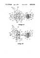
- FIG. 5is a perspective view of the cassette of the present invention along with the flow regulator shutoff assembly of a driver mechanism used to operate the cassette of the present invention
- FIG. 6is a detailed view partially in section of the cassette mounted in a door of a driver having a regulator shutoff assembly
- FIGS. 7-9are detailed views of the regulator shutoff assembly of a driver employed to operate the cassette of the present invention.
- FIG. 10illustrates the air in-line detection system of the cassette of the present invention
- FIG. 11is a cross section taken along the plane of line 11 of FIG. 1;
- FIG. 12is a sectional view of an acoustic coupling employed in the air-in-line detection system of the present invention.
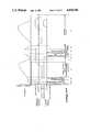
- FIG. 13is a front elevation of a portion of the front panel on the driver employed to drive the cassette of the present invention shown with the cassette door removed;
- FIG. 14is a cross section taken along the plane of line 14--14 of FIG. 13 showing a cassette of the present invention in phantom;
- FIG. 15is a detailed perspective view of the cassette primary and secondary inlet actuator drive assembly of the present invention.
- FIG. 16is a detailed front elevational view of the cassette primary and secondary inlet actuator drive assembly of the present invention.
- FIGS. 17-19are detailed side elevational views of the cassette inlet and outlet actuator drive assembly of the present invention.
- FIG. 20is a detailed side elevational view of the pumping chamber inlet and outlet actuator drive assembly of the present invention.
- FIG. 21is a detailed plan view of the pumping chamber inlet and outlet actuator drive assembly of the present invention.
- FIGS. 22 A-Care schematic views of various positions of the positioning flag for the cassette inlet and outlet actuator drive assembly
- FIGS. 23 A-Care schematic views of various positions of the positioning flag for the pumping chamber inlet and outlet actuator drive assembly.
- FIG. 24is a graphical representation of the pumping sequence of the cassette driver of the present invention.
- FIG. 25is a schematic of the operating system of the cassette driver of the present invention.
- a pumping cassette 10 of the present inventionis illustrated in FIGS. 1-4. It includes a rigid face member 12 and a rigid back member 14 with an elastomeric member 16 positioned between. Face member 12 has plunger opening 18 with elastomeric member 16 extending across the opening. Behind plunger opening 18 in back member 14 is an enlarged recess 20, which forms a pumping chamber 22.
- a plunger 24(FIG. 1) reciprocates into and out of opening 18 urging the diaphragm across opening 18 into and out of chamber 22.
- a pumping chamber outlet valve actuator 26is opened while the pumping chamber inlet valve actuator 28 is closed so that fluid is forced from chamber 22 out of the cassette outlet 30.
- cassette 10further includes air-in-line detection means 34 in the fluid path between primary cassette inlet 64 and pumping chamber 22, and air-in-line detection means 36 the fluid path between pumping chamber 22 and cassette outlet 30. Detection means 34 and 36 can be used to detect whether air is being drawn into the system and whether the valves in the cassette are working properly to prevent fluid from flowing at an uncontrolled rate through the cassette.
- Face member 12is preferably molded from rigid plastic such as polycarbonate. Face member 12 has a generally flat exterior face 38-flat with the exception of a semi circular guard member 40 for air in-line detection means 34, a semi-circular guard member 42 for air-in-line detection means 36, and a cylindrical housing 44 for a flow control regulator 46.
- the interior face 46 of face member 12is flanged, having a peripheral pair of flanges 48 and 50, which extend completely around the peripheral face member 12 toward back member 14. Flanges 48 and 50 are spaced from each other and receive between them a peripheral flange 52 of the elastomeric member 16.
- Interior face 46 of face member 12also includes flanges 56 on either side of the fluid path through cassette 12 in the outline of the fluid path (see FIG. 2) which pinch or retain elastomeric member 16 against the interior face 54 of back member 14 to prevent fluid from leaking out of the fluid path into other areas within cassette, not part of the fluid path.
- flanges 56on either side of the fluid path through cassette 12 in the outline of the fluid path (see FIG. 2) which pinch or retain elastomeric member 16 against the interior face 54 of back member 14 to prevent fluid from leaking out of the fluid path into other areas within cassette, not part of the fluid path.
- Face member 12also includes valve actuator openings.
- a primary cassette inlet valve actuator opening 62is located adjacent primary cassette inlet 64 to allow a finger-like primary inlet actuator 66 to regulate the flow of fluid into the cassette.
- Inlet actuator 66extends through opening 62 and is selectively moved inwardly of opening 62 to urge a portion of the elastomeric member 16 across the fluid path and against the inside surface of back member 14 to block the flow of fluid into cassette 10 from inlet 64.
- the inlet actuator opening 62 and the portion of elastomeric member 16 adjacent opening 62form a primary cassette inlet valve.
- a secondary cassette inlet actuator opening 58is located adjacent a secondary cassette inlet 32. Opening 58 permits a secondary inlet actuator 60 to urge a portion of elastomeric member 16 across the fluid path and against the inside surface of back member 14 so as to block the flow of fluid from secondary inlet opening 32 into the cassette. Inlet actuator opening 58 and the portion of elastomeric member 16 adjacent opening 58 form a secondary cassette inlet valve.
- Primary inlet 64 and secondary inlet 32can be connected to primary and secondary sources of fluid.
- Actuators 66 and 60are used to select which fluid is pumped by cassette 10 at any given moment, if two liquids are being pumped to the patient at a given time. Alternatively, if one liquid is being administered, the liquid container is connected to primary inlet 64, and the primary cassette inlet valve is opened while the secondary cassette inlet valve is closed during fluid administration. The mechanism used to drive inlet actuators 66 and 60 is described below.
- a pump chamber inlet actuator opening 68(FIGS. 1 and 3) is located upstream of the fluid path leading to pump chamber inlet 70 (FIG. 2) which is positioned at the bottom of pump chamber 22.
- Actuator opening 68allows actuator 28 to urge a portion of elastomeric member 16 adjacent opening 68 across the fluid path leading into pump chamber 22 to block the flow of fluid into pump chamber 22 from cassette inlets 32 and 62 and to block the flow of fluid from pump chamber 22 back through cassette inlets 32 or 62.
- Pump chamber inlet actuator opening 68 and the portion of elastomeric member 16 adjacent opening 68form a pump chamber inlet valve.
- a pump chamber outlet actuator opening 72(FIGS. 1 and 4) is provided through face member 12 to allow a pump chamber outlet actuator 26 to urge a portion of elastomeric member 16 across the fluid path leading from pump chamber outlet 74 (FIGS. 2 and 4) to selectively block the flow of fluid from chamber 22 out of outlet 74. Opening 72 and the portion of elastomeric member 16 adjacent opening 72 form a pump chamber outlet valve.
- back member 14has a concave, circular valve seat 75 opposite each actuator opening 58, 62, 68, and 72.
- Each valve actuator 26, 28, 60, and 66has a rounded end so that when a valve actuator is urged inwardly through an actuator opening, a portion of the elastomeric member 16 will be urged into a valve seat 75, insuring that flow is blocked when an actuator is actuated.
- Face member 12further includes a pressure sensor opening 76 which allows a rod-like extension 78 of a pressure sensor 77 (FIG. 14) associated with the pump cassette driver (not shown) to contact a pressure detection section 80 (FIG. 4) of elastomeric member 16 positioned over a pressure chamber 82 in back member 14.
- a pressure sensor opening 76which allows a rod-like extension 78 of a pressure sensor 77 (FIG. 14) associated with the pump cassette driver (not shown) to contact a pressure detection section 80 (FIG. 4) of elastomeric member 16 positioned over a pressure chamber 82 in back member 14.
- Back member 14is also made of a rigid, polymeric material preferably polycarbonate.
- Back member 14includes a peripheral flange 86 (FIGS. 3 and 4) in which peripheral flange 48 of face member 12 nests. Flanges 48 and 86 are secured together in a sealed fashion by welding, gluing and the like.
- back member 14includes cassette inlets 64 and 32.
- Secondary inlet 32is provided with a luer taper 33 and thread like flanges 35 to accept a luer cap for capping inlet 32 when only one liquid is to be pumped, or connecting to a luer lock tubing connector when two liquids are to be pumped.
- Back member 14also includes a recess 20 which forms pumping chamber 22 and a recess 82 which forms a pressure detection chamber.
- a reservoir recess 88is also provided in back member 14 to form a reservoir 90 (FIGS. 2 and 3) when the unit is assembled.
- Reservoir 90has an inlet 92 at the top of reservoir 90, and an outlet 94 above the bottom 96 of reservoir 93.
- the cassetteWhen the cassette is initially primed with liquid prior to pumping, the cassette is inverted from the position shown in FIG. 2 so that the air in the fluid path between cassette inlets 32 and 62 and pumping chamber inlet 70 is displaced with liquid with the exception of the air trapped between the bottom 96 and outlet 94 of drip chamber 90.
- This trapped volume of air 93rises to the top of drip chamber 90 when the cassette is returned to its upright pumping position shown in FIGS. 2 through 4. The function of trapped air 93 will be explained below.
- Reservoir 90, pressure detection chamber 82, and pumping chamber 22form portions of the fluid path between cassette inlets 32 and 62 and cassette outlet 30. The remaining portions of the fluid path are also formed on the inside surface 54 of back member 14.
- An inlet passage 104(FIGS. 3 and 17) connects primary inlet 64 to an opening 105 (FIG. 3) inside of the cassette.
- Secondary inlet 32is connected with an opening 103 in cassette 10 by an inlet passage 102 (FIGS. 2 and 10). Fluid from openings 103 and 105 combine in a channel 106 (FIGS. 2 and 3), formed between membrane 16 and back member 14 and flows into air-in-line detection means 34, which will be described in detail below.
- the fluidflows through reservoir inlet 92 into reservoir 90. From reservoir 90, the fluid enters a passage 108, valved at its lower end by pump chamber inlet valve actuator 28 into pumping chamber 22 through pumping chamber inlet 70. A short channel 110 valved by pump chamber outlet valve actuator 28 connects pump chamber outlet 74 to pressure detection chamber 82. The fluid flows through pressure detection chamber 82 into air-in-line detection means 36. From air-in-line detection means 36, fluid flows through a channel 112 which leads to flow control regulator 45.
- flow regulator 45includes a plunger 47 and a cylindrical housing 44.
- Plunger 47 and housing 44are configured to allow plunger 47 to be threaded inwardly of housing 44 to reduce or prevent the flow of fluid through regulator 45, or to be threaded outwardly of cylindrical housing 44 to increase or allow fluid to flow through regulator 45.
- plunger 47can be used to regulate manually the flow of fluid through the cassette when the cassette is not mounted in a driver, permitting regulated gravity flow of fluid from the I.V. solution container to the patient.
- the cassette of the present inventioncan be employed without the cassette driver to regulate flow of I.V. solution to the patient. But, when the patient arrives at the hospital, the cassette can be mounted on a cassette driver described in more detail below to regulate the flow of fluid more precisely than with the manual gravity method described above.
- flow regulator plunger 47is adapted to be pushed inwardly into or pulled outwardly of cylindrical housing 44 to allow rapid movement between on and off positions.
- the cassette driver mechanismincludes a flow regulator shutoff assembly 114 (FIGS. 5-9) to pull plunger 47 rapidly outward into the open position when the cassette is mounted in the driver, and to push plunger 47 inward into the "off" position when the cassette is removed from the driver.
- Flow regulator shutoff assembly 114includes a gripper bracket 116 having two downwardly depending arms 118, 118' joined in a bight portion 120 at their upper ends. Pivotally mounted between arms 118, 118' is a chevron-shaped depressor member 122. Depressor member 122 is pivotally mounted to and between arms 122 by a pin 124. Depressor member 122 is also pivotally mounted about a pin 126 which is fixedly mounted on the chassis 128 of the cassette driver assembly.
- cam 130Also mounted between arms 118 and 118' is a cam 130 which is fixedly mounted on a rotatable shaft 132.
- Cam 130has cam surfaces 134 and 134' which engage corresponding cam surfaces 136 and 136' on the inside of depressor member 122.
- Cam 130further includes a driving pin 138 which extends through 130 to engage the lower ends of arms 118 and 118' in a manner to be described below.
- Flow regulator shutoff assembly 114further includes a slotted pivot arm 140 which is fixedly secured to rotatable shaft 132 which in turn is mounted on chassis 128 so as to allow shaft 132 to rotate freely about its longitudinal axis but to restrain it from translational movement in horizontal or vertical directions. Pivot arm 140, therefore, will pivot in tandem with cam 130.
- Pivot arm 140has a slot 142 in which a roller 144 is free to slide. Roller 144 is mounted on the driver door 146 in which cassette 10 is mounted when in the driver.
- the driver door 146is pivotally mounted on a pin 148 which is also fixedly secured to chassis 128 of the driver.
- pivot arm 140when driver door 146 is open, pivot arm 140 is in a substantially horizontal position with roller 144 at the distal end 150 of slot 142.
- roller 144travels in slot 142 and forces pivot arm 140 to rotate in a counterclockwise position from the position shown in FIG. 6 to the position shown in FIG. 5 where roller 144 is in the proximal end 152 of slot of 142.
- pivot arm 140As pivot arm 140 pivots from the substantially horizontal position shown in FIG. 6 to the substantially vertical position shown in FIG. 5, it rotates shaft 132 since pivot arm 140 is fixedly attached to shaft 132. As shaft 132 rotates in a counterclockwise position, it forces cam 130 to do likewise.
- cam 130rotates counterclockwise (FIG. 7)
- the ends of driving pin 138engage the lower ends of arms 118, forcing gripper bracket 116 to pivot about pin 124.
- the counterclockwise rotation of cam 130forces depressor member 122 to pivot about pin 126.
- the counterclockwise rotation of cam 130forces cam surface 134 against cam surface 136 to urge depressor member to rotate in a clockwise direction about pin 126 until cam surface 134' engages cams surface 136' as shown in FIG. 7.
- pivot arm 140pivots from the substantially vertical position shown in FIG. 5 toward the substantially horizontal position shown in FIG. 6, forcing cam 130 to rotate clockwise(FIG. 8).
- driving pin 138releases the lower ends of arms 118, and a spring 150 between gripper bracket 116 and depressor member 122 urges gripper bracket 116 to pivot clockwise about pin 124 to return to the position of FIG. 6.
- cam surface 134'engages cam surface 136' to force depressor member 122 to pivot in a clockwise direction about pin 126 to return to the position of FIG. 6 from the position of FIG. 7, the position of FIG. 8 being an intermediate position between the positions of FIGS. 6 and 7.
- the lower ends of arm 118include gripper fingers 152.
- the knob 49 (FIGS. 6-9) of plunger 47passes beneath the ends of fingers 152 to a position adjacent to the lower end of depressor member 122.
- cam 130drives gripper bracket 116 and depressor member 122 toward the "closed" position of FIG. 7, fingers 152 trap knob 49 between fingers 152 and the lower end of depressor member 122 and pull plunger 47 outwardly of cylindrical housing 44 to open the flow regulator 45 completely.
- roller 144forces pivot arm 140 to rotate cam 130 in a counterclockwise direction which allows fingers 152 to move away from the lower end of depressor member 122 to release knob 49 from flow regulator shutoff assembly 114.
- cam 130pivots depressor member 122 such that the lower end of depressor member 122 depresses or urges plunger 47 inwardly of housing 44 (see FIGS. 8 and 9) so that flow regulator 45 is closed and prevents fluid from flowing through the cassette.
- the flow regulatoris off, and the cassette can be removed. It is important that the flow regulator be turned off before the cassette is removed otherwise, fluid would flow through the cassette in an uncontrolled fashion under the force of gravity.
- shutoff assembly 114When cassette 10 is mounted in the cassette driver and driver door 146 is closed, flow regulator 45 is opened completely by shutoff assembly 114. However, when door 146 is opened to remove cassette 10 from the driver, shutoff assembly closes flow regulator 45 to prevent fluid from flowing through the cassette in an uncontrolled rate. After the cassette is removed, plunger 47 can be manually threaded outwardly of regulator 45 to allow fluid to be administered to the patient at a controlled rate, if desired.
- flow regulator shutoff assembly 114opens flow regulator 45 completely when cassette 10 is mounted on door 146 and door 146 is closed.
- pumping chamber inlet valve actuator 28 and/or pumping chamber outlet valve actuator 26are positioned before pumping begins so as to block flow of fluid through the cassette, as shown in FIG. 14. Accordingly, before the cassette is placed in the cassette driver mechanism, the flow of liquid is controlled manually by flow regulator 45 at a rate set by medical personnel. This manual rate can range from zero to the maximum gravity flow rate through the cassette.
- valve actuators 26 and/or 28stop fluids from flowing through the cassette until the cassette driver pumping sequence and rates are selected by medical personnel.
- flow regulator shutoff assembly 114shuts off flow regulator 45 until flow regulator 45 can be reset manually by medical personnel at the desired rate if such reset is desired.
- the air-in-line detection systemincludes an air-in-line detector 34 located in the fluid path between cassette inlets 32, 64, and drip chamber 90.
- the air-in-line detection systemalso includes an air-in-line detector 36 positioned in the fluid path between pressure detection chamber 82 and flow regulator 45. Air-in-line detectors 34 and 36 are substantially identical to each other.
- the air-in-line detection systemalso includes a pair of ultrasonic detectors mounted on the cassette driver--an ultrasonic detector 154 (FIG. 1) for air-in-line detector 34, and an ultrasonic detector 156 for air in-line detector 36.
- Ultrasonic detector 154is identical to ultrasonic detector 156. Therefore, only air-in-line detector 34 and ultrasonic detector 154 will be described in any detail. Furthermore, they are described in U.S. patent application Ser. No. 045,951 filed on an even date herewith entitled Ultrasonic Detector, the disclosure of which is incorporated herein by reference.
- Air-in-line detector means 34includes a pocket 158 formed integrally as part of elastomeric member 16 (see FIGS. 3, 10 and 11). Pocket 158 extends through an opening 160 (FIG. 11) in face member 12 and projects outwardly beyond the surface of face member 12. Pocket 158 has a hollow recess 162 in it which is formed between two sidewalls 164 and 164' and an arcuate endwall 166. A finger 168 projects from the inner surface of back member 14 into recess 162 and fits interferingly between sidewalls 164 and 164', but does not contact endwall 166. Thus, an arcuate fluid passage 170 (see FIGS.
- Ultrasonic detector 154includes two mirror imaged housing portions 172 and 174.
- Housing member 172is generally L-shaped and is joined to the mirror imaged L-shaped housing 174 at the bottom of the L's so as to form a U-shaped housing assembly with a recess 176 between the arms of the U adapted to receive air-in-line detector 34.
- housing portion 172On one side of recess 176, housing portion 172 has an opening 178, while on the other side of recess 176, housing portion 174 has an opening 180.
- Housing members 172 and 174are hollow, each containing a passage 182 for the necessary electrical contacts.
- Positioned in opening 178is an ultrasonic generator 184, facing an ultrasonic receiver 186 positioned in opening 180.
- Ultrasonic generator 184is positioned directly across recess 176 from ultrasonic receiver 186.
- Elastomeric pocket 158has two resilient lobes 187, 187' (FIGS. 1 and 11) which extend outwardly from sidewalls 164, 164' in opposite directions.
- the width of pocket 158 between lobes 187, 187'is somewhat less than the width of recess 176 between ultrasonic generator 184 and ultrasonic receiver 186 so that lobes 187 and 187' are compressed inwardly toward each other when air-in-line detection means 34 is inserted into ultrasonic detector 154 as shown in FIG. 10. This insures that there will be good acoustic contact between ultrasonic generator 184 and pocket 158 and between ultrasonic receiver 186 and pocket 158.
- an ultrasonic signalcan be transmitted across fluid passage 170 when air-in-line detection means 34 is inserted into recess 176.
- the transmission of ultrasonic sound between ultrasonic generator 184 and ultrasonic receiver 186is greatly enhanced when a liquid is present in passage 170. But when air is present in passage 170, the transmission of ultrasonic sound through fluid passage 170 is attenuated. This difference in ultrasonic sound transmission is detected by ultrasonic receiver 186. When air is present, the electrical signal generated by ultrasonic receiver 186 decreases.
- Ultrasonic detector 154 (and 156)is coupled to a microprocessor 233 (FIG. 25) which receives an amplified signal generated by ultrasonic receiver 186 and subsequently amplified.
- Microprocessor 233is preferably a 63B03R Hitachi microprocessor.
- an alarm 241(FIG. 25) is sounded by processor 233 to stop the pumping of fluid through the cassette if the cassette is in the fluid delivery cycle.
- any air drawn into the cassette from the empty containerswill be drawn through air-in-line detector 34, and the presence of that air will be detected by ultrasonic detector 154.
- Alarm 241 and/or nurse call 242is then sounded, and the cassette driver is stopped to prevent further pumping.
- ultrasonic detector 154If ultrasonic detector 154 malfunctions and does not detect the presence of air, the air pumped will be detected by ultrasonic detector 156. Likewise, if there is an air leak in the system between the fluid container and the outlet of the cassette before the fluid container is emptied, any air drawn into the system will be detected by one or the other ultrasonic detectors 154 or 156 through air-in-line detectors 34 and 36. Other functions of the air-in-line detection system will be explained in the "Operation" section below.
- valve actuators 60 and 66operate the secondary and primary cassette inlet valve, and valve actuators 26 and 28 operate the pumping chamber inlet and outlet valves. Similar mechanisms are employed to operate each of these pairs of valve actuators.
- the valve actuator assembly 188drives valve actuators 60 and 66 (FIGS. 15-19).
- Valve actuator assembly 188includes a first bracket 190 which drives valve actuator 66.
- First bracket 190includes two arms 194 and 196 which are spaced from and perpendicular to each other, and joined to each other by a bight portion 198.
- First bracket 190is pivotally mounted on the chassis 128 of the driver by a pivot pin 200 which is located at the proximal ends of arms 194 and 196 joined by portion 198 so that arms 194 and 196 pivot about a common pivot point when operated as described below.
- Valve actuator 66is pivotally secured to the distal, free end of arm 194.
- the distal, free end of arm 196is driven by a cam 201 as described below.
- Valve actuator assembly 188also includes a second bracket 192 with two spaced, perpendicular arms 202 and 203, which are joined to each other by a bight portion 204.
- Second bracket 192is pivotally mounted to chassis 128 by a pivot pin 205 which is located at the ends of arms 202 and 203 joined by bight portion 204.
- the free end of arm 202is pivotally connected to valve actuator 60.
- the free end of arm 203engages cam 201 described below.
- a primary spring 206biases brackets 190 and 192 around pins 200 and 205 such that arms 196 and 203 are urged toward cam 201.
- One end of spring 206is connected to a tab 207 which extends from bight portion 198.
- the other end of primary spring 206is connected to a tab 208 which extends from the proximal end of arm 202.
- Tabs 207 and 208generally extend toward cam 201 so that spring 206 will bias arms 196 and 203 toward cam 201.
- a secondary spring 209is attached to and between bight portions 198 and 204 to urge arms 196 and 203 away from cam 201 in the event that primary spring 206 breaks.
- secondary spring 209is weaker than primary spring 206 such that when the two springs are operable, arms 196 and 203 will be urged toward cam 201. If primary spring 206 breaks, secondary spring 209 will urge brackets 190 and 192 to pivot around pins 200 and 205 such that arms 196 and 203 pivot away from cam 201.
- the distal end of arm 196includes a flag portion 191 (FIGS. 17 and 18) which passes through an optical switch 193 in the event of primary spring breakage.
- brackets 190 and 192When optical switch 193 is tripped, a signal is relayed to processor 233 which stops the driver immediately and sounds alarm 241 and/or nurse call 242.
- a stop 195is positioned adjacent cam 201, and brackets 190 and 192 have stop tabs 197 and 199 which project from the proximal ends of arms 196 and 203. If primary spring 206 breaks, brackets 190 and 192 will pivot around pins 200 and 205 until stop tabs 197 and 199 contact stop 195 at which point flag portion 191 would have passed through switch 193 and 191 flag portion will continue to block light passing through the switch.
- actuators 60 and 66are elongated rods. As indicated previously, the proximal ends of actuators 60 and 66 are pivotally connected to arms 194 and 202 of brackets 190 and 192, respectively. The distal ends of actuators 60 and 66 are supported in openings 250 and 251 (FIGS. 13 and 17-19) in the front panel 252 of the driver.
- Cam 201is circular in shape and is eccentrically mounted on a motor shaft 210. Shaft 210 is operated by a stepper motor 211 (FIG. 16).
- cam 201is moved to the position where both valve actuators 60 and 66 are fully extended (FIG. 17) toward cassette 10 so as to close the primary and secondary cassette inlet valves.
- valve actuators 60 and 66urge elastomeric member 16 across the fluid passages leading from inlets 103 and 105 into the cassette.
- primary inlet actuator 66is retracted by the clockwise rotation of cam 201 by motor 211 from the position shown in FIG.
- Cam 201engages arm 196 of bracket 190 and urges bracket 190 to pivot clockwise about pivot pin 200 against the bias of spring 206.
- arm 194retracts actuator 66, thereby allowing liquid to flow through primary cassette inlet 64 through opening 105.
- cassette inlet valve actuator assembly 188allows the following possible cassette inlet valve positions: (1) both the primary and secondary cassette inlet valves closed; (2) the primary inlet valve open and the secondary inlet valve closed; and (3) the secondary cassette inlet valve open and the primary cassette inlet valve closed. In normal operation, valve actuator assembly 188 does not permit both the primary and secondary cassette inlet valves to be open simultaneously.
- a second valve actuator assembly 212is used to operate pumping chamber outlet and inlet valve actuators 26 and 28 (FIGS. 20-21).
- Pumping chamber outlet valve actuator 26is operated by a first bracket 213 which is pivotally mounted on a pivot pin 214 on chassis 128.
- First bracket 213has two spaced, perpendicular arms 215 and 216 fixedly secured and integrally formed with a bight portion 217.
- the proximal end of arm 215is pivotally secured to pivot pin 214, and the distal end of arm 215 is pivotally secured to actuator 26.
- the proximal end of arm 216is pivotally mounted to pivot pin 214, and the distal end of arm 216 is urged toward a cam 218 described below by a spring 219.
- spring 219biases first bracket 213 such that arm 216 will be urged toward a cam 218.
- Valve actuator assembly 212also includes a second bracket 222 pivotally mounted about pivot pin 214.
- Second bracket 222includes a first arm 223, the proximal end of which is pivotally secured to pin 214, and the distal end of which is pivotally secured to the proximal end of valve actuator 28.
- Second bracket 222also includes a second arm 224, the proximal end of which is pivotally secured about pin 214, the distal end of which is free to be engaged by cam 218.
- Arms 223 and 224are perpendicular to each other and fixedly joined to each other by a bight portion 225.
- Second bracket 222further includes a tab 225 which extends from the proximal end of second arm 224.
- the free end of tab 225is attached to one end of a spring 226 which biases arm 224 toward cam 218.
- the other end of spring 226is attached to a tab 227 which is raised from chassis 128.
- Cam 218is eccentrically mounted on a motor shaft 228 operated by a stepper motor 229. As cam 218 is driven by motor 229 in counterclockwise from the position shown in FIG. 20, cam 218 engages arm 216, forces first bracket 213 to pivot counterclockwise about pin 214, and causes valve actuator 26 to retract against the bias of spring 219. When valve actuator 26 is retracted, the pumping chamber outlet valve is opened. When cam 218 is driven counterclockwise against arm 216, arm 224 of bracket 222 remains stationary, and spring 226 will force valve actuator 28 to remain extended against the pumping chamber inlet valve, keeping the pumping chamber inlet valve closed. As cam 218 is driven by motor 229 in a clockwise from the position shown in FIG.
- valve actuator assembly 212permits both the pumping chamber inlet and outlet valves to be closed, or allows only one of them to be opened at a time. More importantly, valve actuator assembly 212 prevents both the pumping chamber inlet and outlet valves from being opened simultaneously so that fluid cannot flow through the cassette at an uncontrolled rate under the force of gravity during the pumping cycle.
- actuators 26 and 28are pivotally connected to brackets 215 and 223, as indicated above.
- the distal ends of actuators 26 and 28are supported in openings 254 and 256 (FIGS. 13 and 14) in front panel 252. Since valve actuator assemblies 188 and 212 are driven by separate motors 211 and 229, and since plunger 24 is driven by a motor separate from stepper motors 211 and 229, the three motors must be operated in a synchronized fashion, and the positions of each during the operations of the cassette driver must be monitored.
- Flag 230is fixedly mounted on cam 201.
- Flag 230is thin, pie shaped strip of metal with a small notch 231 on its radially outer edge.
- motor 211takes a set number of steps, preferably 24 steps.
- Notch 231is not centered on the radially outer edge of flat 230, but offset to one side.
- Valve actuator assembly 188further, includes, an optical switch 232 through which the radially outer edge of flag 230 passes as cam 201 moves from position shown in FIG. 18 to the position shown in FIG.
- Optical switch 232passes a beam of light across the space through which flag 230 passes.
- Flag 230breaks the beam of light, except for notch 231 which allows light to pass when notch 231 passes through switch 232.
- Optical switch 232is coupled to microprocessor 233 (FIG. 25) to relay to microprocessor 233 whether light is being transmitted or whether it is being blocked by flag 230.
- Microprocessor 233also controls stepper motor 211 such that as the stepper motor 211 moves stepwise clockwise or counterclockwise, the microprocessor can determine whether cam 201 is out of position. For instance, as flag 230 passes through switch 232 as it moves from the position shown in FIG. 18 to the position shown in FIG.
- cam 218has a flag 236 attached to it.
- Flag 236is generally pie shaped, having a radially outer edge with a notch 237 in it.
- An optical switchis positioned so that flag 236 passes through it as flag 236 moves from the position shown in FIG. 22(B) where valve actuator 26 is retracted to the position shown in FIG. 22(C) where valve actuator 28 is retracted.
- Notch 237is likewise offset to provide a small radially outer edge portion 239 and a large radially outer edge portion on either side of notch 237.
- switch 238will detect a short period of darkness as radially outer edge portion 239 passes, a short period of light when notch 237 passes, and a long period of darkness as portion 240 passes through switch 238.
- Microprocessor 233is coupled to optical switch 238 such that the periods of light and darkness can be correlated stepwise to the number of steps taken by stepper motor 229 between the positions of FIGS. 22(C) and 22(B). Therefore, as flag 236 moves back and forth between these two positions opening and closing the pumping chamber inlet and outlet valves, microprocessor 233 can compare the actual position of cam 218 (and hence the positions of valve actuators 26 and 28) with the desired, preprogrammed position to either advance or retard stepper motor 229 appropriately.
- cams 201 and 218are checked before pumping begins.
- motor 211will drive cam 201 back and forth between the positions shown in FIGS. 18 and 19 while optical switch 232 checks the actual position of flag 230, and microprocessor 233 will stop stepper motor 211 once it is determined that cam 201 is in the proper position to begin the pumping sequence.
- that positionwill be when valve actuator 56 is retracted and valve actuator 60 is extended (FIG. 18).
- motor 229will move flag 236 and cam 218 back and forth between the positions of FIGS. 22(B) and (C) to position the pumping chamber inlet and outlet valve actuators 26 and 28 in their appropriate positions to begin the pumping cycle, namely, with both valve actuators 26 and 28 fully extended, (i.e., the positions shown in FIGS. 20, and 22(A)).
- the pumping chamber inlet and outlet valvescan be checked according to the procedure described below. Once microprocessor 233 verifies that flag 236 is in the proper position, the valve checking sequences and pumping sequences described below can commence.
- Plunger 24is also operated with a stepper motor (not shown).
- An optical flagis also attached to the plunger stepper motor shaft so that an optical switch (not shown) and microprocessor 233 monitor and position plunger 24 before and during the pumping cycle to synchronize plunger 24 with the operation of actuators 26, 28, 60, and 66.
- the liquid container with the liquid to be pumpedis connected to primary cassette inlet 64, and the secondary cassette inlet 32 is closed with a luer-type locking cap (not shown).
- the cassetteis primed with fluid by opening regulator 45 and initially inverting the cassette from the position shown in FIG. 2 to purge the fluid path between the cassette inlets and the pumping chamber of air (except, of course, for the trapped volume 100).
- the pumping chamber and the fluid path beyond itare purged of air by returning the cassette to the upright position of FIG. 2.
- Regulator 45is then either closed or set manually to a desired flow rate until the cassette is mounted in the cassette driver. Once the cassette is mounted in the driver, the flow regulator shutoff assembly 114 automatically opens regulator 47 and the cassette valves are tested as described below.
- Step BWith valve actuators 26 and 28 in the extended positions, plunger 24 is urged against elastomeric member 16 across plunger opening 18 to pressurize pumping chamber 22 (Step B). Plunger 24 is held in this position for the "WAIT" period (Step C), pressurizing chamber 22 for a short period of time, whereupon outlet valve actuator 26 is retracted to allow pressurized liquid to escape pumping chamber 22, while inlet valve actuator 28 is held in its "extended” position (Step D). When outlet valve actuator 26 is released (Step D), the pressurized liquid within chamber 22 surges into pressure detection chamber 82, producing a pressure pulse or spike in chamber 82.
- microprocessor 233compares the value of the signal generated by sensor 77 to a stored value. If the stored value is significantly greater, microprocessor 233 will sound an alarm 241 and a nurse call 242 and the pump driver will not function unless a new cassette is used.
- the pump chamber inlet and outlet valve test procedure described aboveis first done automatically by the cassette driver immediately after the driver is started. Thereafter, the same test procedure can be done periodically during fluid delivery to insure the continuing integrity of the pumping chamber inlet and outlet valves during fluid delivery.
- the test procedureis performed periodically in the fashion illustrated in FIG. 24, steps A-E.
- the pumping chamber inlet valveis closed (step A) while the pumping chamber outlet valve is closed.
- Chamber 22is pressurized by extending plunger 24 a short distance into chamber 22 (step B).
- the plungeris held for the "WAIT" period (step C).
- the pumping chamber outlet valveis opened and the pressure spike detected in chamber 22 (step D). If the pressure spike is of sufficient magnitude, plunger 24 extends further into chamber 22, (step E) to displace the rest of the fluid in chamber 22 and pump it into the patient.
- the pumping chamber outlet valveis closed (last part of step E), and the inlet valve is opened (step F) while the plunger is retracted to fill the pumping chamber with liquid.
- air-in-line detector 34can be used to establish whether the cassette inlet valves associated with primary cassette inlet 64 and secondary cassette inlet 32 are working properly.
- the pumping chamber outlet valveis closed and the pumping chamber inlet valve is open (end of step E).
- the two inlet valves 64 and 32are closed (step G), and plunger 24 pressurizes pump chamber 22 (step H).
- the systemis then held pressurized for a short period of time (step I). If either of the two cassette inlet valves leak, liquid will flow out of the primary cassette inlet 64 or secondary cassette inlet 32.
- the pumping chamber inlet valveis closed and the pumping chamber outlet is opened whereupon plunger 24 is urged through opening 18 against elastomeric member 16 to displace the fluid from pumping chamber 22 out cassette outlet 30 to the patient.
- the amount of fluid during the fluid delivery strokeis controlled precisely by operating plunger 24 with a conventional stepping motor.
- the displacement of plunger 24 against elastomeric member 16can be controlled precisely for each delivery stroke by advancing the stepper motor the same number of steps for each delivery stroke such that a constant volume of fluid is displaced from pumping chamber 22 for each stroke.
- the pumping chamber outlet valveis closed, the pumping chamber inlet and the primary cassette inlet valves are opened, and then plunger 24 is retracted the same number of steps it was advanced during the previous fluid delivery stroke. Since both the pumping chamber inlet valve and the primary cassette inlet valve are opened, fluid will be drawn from the fluid container connected to the primary cassette inlet as plunger 24 is retracted stepwise. Once plunger 24 is retracted to its starting or "home" position, the pumping chamber inlet and the primary cassette inlet valves are closed and the pumping chamber outlet valve is opened for the next stepwise fluid delivery stroke of plunger 24.
- the fluid delivery strokeis then repeated, followed by the pumping chamber refill retraction stroke by plunger 24, with the pumping chamber inlet and outlet valves appropriately valving the flow of fluid on delivery and refill.
- the pumping of fluid when a single fluid is being pumpedis fairly simple and straightforward.
- the container containing the primary liquidis connected to the primary cassette inlet 64.
- the secondary liquid containeris connected to the secondary cassette inlet 32 by removing the luer lock cap on inlet 32 and connecting the secondary fluid container to inlet 32 with a luer connector.
- the valving of the pumping chamber inlet and outlet valves during fluid delivery and pumping chamber refill strokesare the same during a two fluid delivery as with the single fluid delivery procedure described above.
- the cassette inlet valvingis different.
- the secondary cassette inlet valveis always closed and only the primary inlet valve is open during the refill of the pumping chamber.
- the primary and secondary cassette inlet valvesare each opened and closed for selected periods of time during the pumping chamber refill stroke. For instance, if the two fluids are to be mixed in a fifty-fifty proportion, the primary cassette inlet valve is opened during the first half of the total number of strokes comprising the pumping chamber refill stroke of plunger 24. During the first half of the retraction stroke of plunger 24, the secondary cassette inlet valve is closed. However, during the second half of the retraction/refill stroke of plunger 24, the secondary cassette inlet valve is opened while the primary cassette inlet valve is closed. Since plunger 24 is controlled stepwise, it is possible to ascertain exactly when to switch the two cassette inlet valves from open to closed and vice versa to achieve the desired proportioning of the two fluids.
- the primary fluidis a diluent such as saline solution whereas the secondary fluid is a concentrated drug.
- the secondary cassette inlet valvemay be opened only 10 to 20 percent of the steps during the pumping chamber refill stroke of plunger 25 while the primary cassette inlet valve is opened 80 to 90 percent of the steps comprising the refill stroke of plunger 24.
- cassette and driver of the present inventionsimply by operating inlet actuator 60 and 66 in sequence and in tandem with plunger 24 during the pumping chamber refill stroke as described above. Because cassette inlet actuators 60 and 66 cannot be simultaneously retracted as described above (i.e., one is always extended closing its cassette inlet valve), one cannot get gravity flow between the primary and secondary fluid containers through the cassette.
- pressure sensor 77 and pressure detection chamber 82are employed to detect whether the pumping chamber inlet and outlet valves are functioning properly. However, once the pumping chamber inlet and outlet valves are checked for proper functioning, pressure sensor 77 and pressure detection chamber 82 can also be used to monitor the patient's blood pressure.
- the pumping chamber outlet valveis closed such that the pressure of the fluid in the fluid path from the pumping chamber outlet valve to the patient is at the patient's blood pressure.
- the patient's blood pressureis stored memory 243.
- microprocessor 243will sound alarm 241 and/or nurse call 242 to alert medical personnel.
- Pressure sensor 77is also used to detect occlusions in the line leading from the cassette outlet to the patient.
- the pressure in pressure chamber 82is monitored by sensor 77 and microprocessor 233. If the pressure is excessive, it indicates the patient line has been wholly or partially occluded. Microprocessor 233 sounds alarm 241 and nurse call 242.
- Air-in-line detectors 154 and 156are also interfaced with microprocessor 233 (FIG. 25) so that microprocessor 233 will stop the driver and sound alarm 241 and nurse call 242 if air is detected in the cassette or if detector 154 detects a bad inlet valve.
- a LCD/LED display 244(FIG. 25) is also interfaced with microprocessor 244 so that input or output values of delivery rates, delivery volumes, patient blood pressure and the like can be displayed to an operator. Likewise, message codes can be displayed to tell the operator why an alarm has been sounded.
- a keyboard 245is provided to input values of delivery rates, delivery volumes, patient blood pressure, concentration and the like.
- Microprocessor 233can be programmed to deliver a given volume of primary or secondary fluid over a desired period of time, for instance. It is also programmed to set the concentration of secondary liquid in primary solution when two liquids are simultaneously delivered.
- An AC/DC power supply 246is provided and includes a battery charger to continuously monitor and charge batteries provided in the driver for operation without AC current. In the event of power failure, alarm 241 is sounded.
- a dataway 247is provided to allow a printer or other display to be connected to the driver to get data printouts of patient blood pressure over time, and fluid delivery times, volumes and rates.
Landscapes
- Health & Medical Sciences (AREA)
- Heart & Thoracic Surgery (AREA)
- Vascular Medicine (AREA)
- Engineering & Computer Science (AREA)
- Anesthesiology (AREA)
- Biomedical Technology (AREA)
- Hematology (AREA)
- Life Sciences & Earth Sciences (AREA)
- Animal Behavior & Ethology (AREA)
- General Health & Medical Sciences (AREA)
- Public Health (AREA)
- Veterinary Medicine (AREA)
- Emergency Medicine (AREA)
- Infusion, Injection, And Reservoir Apparatuses (AREA)
Abstract
Description
Claims (22)
Priority Applications (12)
| Application Number | Priority Date | Filing Date | Title |
|---|---|---|---|
| US07/045,959US4818186A (en) | 1987-05-01 | 1987-05-01 | Drive mechanism for disposable fluid infusion pumping cassette |
| DE19883876143DE3876143T2 (en) | 1987-05-01 | 1988-04-25 | DISPOSABLE INFUSION CASSETTE WITH PUMP CHAMBER AND ENGINE DAFUER. |
| ES88106575TES2036616T3 (en) | 1987-05-01 | 1988-04-25 | DISPOSABLE CASSETTE OF PUMPING CHAMBER FOR INFUSION OF FLUIDS AND ITS DRIVING MECHANISM. |
| EP19880106575EP0293592B1 (en) | 1987-05-01 | 1988-04-25 | Disposable fluid infusion pumping chamber cassette and drive mechanism thereof |
| DK235888ADK235888A (en) | 1987-05-01 | 1988-04-28 | CASE FOR INFUSION PUMP ROOMS AND DRIVING MECHANISM THEREOF |
| AU15318/88AAU618258B2 (en) | 1987-05-01 | 1988-04-29 | Disposable fluid infusion pumping chamber cassette and drive mechanism thereof |
| CA000565509ACA1310873C (en) | 1987-05-01 | 1988-04-29 | Disposable fluid infusion pumping chamber cassette and drive mechanism thereof |
| JP63109844AJP2763005B2 (en) | 1987-05-01 | 1988-05-02 | Pump cassette for liquid injection and fluid pump cassette device using the same |
| CA000616194ACA1323811C (en) | 1987-05-01 | 1991-10-09 | Mechanism for actuating a plunge-type slideable valve |
| CA000616195ACA1324047C (en) | 1987-05-01 | 1991-10-09 | Driver for driving a disposable fluid-pumping cassette |
| GR930400156TGR3006909T3 (en) | 1987-05-01 | 1993-01-28 | |
| JP9227959AJP2769460B2 (en) | 1987-05-01 | 1997-08-25 | Plunger type slide valve shut-off device |
Applications Claiming Priority (1)
| Application Number | Priority Date | Filing Date | Title |
|---|---|---|---|
| US07/045,959US4818186A (en) | 1987-05-01 | 1987-05-01 | Drive mechanism for disposable fluid infusion pumping cassette |
Publications (1)
| Publication Number | Publication Date |
|---|---|
| US4818186Atrue US4818186A (en) | 1989-04-04 |
Family
ID=21940763
Family Applications (1)
| Application Number | Title | Priority Date | Filing Date |
|---|---|---|---|
| US07/045,959Expired - LifetimeUS4818186A (en) | 1987-05-01 | 1987-05-01 | Drive mechanism for disposable fluid infusion pumping cassette |
Country Status (1)
| Country | Link |
|---|---|
| US (1) | US4818186A (en) |
Cited By (148)
| Publication number | Priority date | Publication date | Assignee | Title |
|---|---|---|---|---|
| US5000664A (en)* | 1989-06-07 | 1991-03-19 | Abbott Laboratories | Apparatus and method to test for valve leakage in a pump assembly |
| US5000663A (en)* | 1989-09-05 | 1991-03-19 | Pacesetter Infusion, Ltd. | Automatic tubing lock for ultrasonic sensor interface |
| US5006050A (en)* | 1988-12-09 | 1991-04-09 | James E. Cooke | High accuracy disposable cassette infusion pump |
| US5039279A (en)* | 1990-03-15 | 1991-08-13 | Abbott Laboratories | Sensor for detecting fluid flow from a positive displacement pump |
| US5055001A (en)* | 1990-03-15 | 1991-10-08 | Abbott Laboratories | Volumetric pump with spring-biased cracking valves |
| US5062774A (en)* | 1989-12-01 | 1991-11-05 | Abbott Laboratories | Solution pumping system including disposable pump cassette |
| US5082014A (en)* | 1989-12-01 | 1992-01-21 | Abbott Laboratories | Solution pumping system including disposable pump cassette |
| US5098262A (en)* | 1990-12-28 | 1992-03-24 | Abbott Laboratories | Solution pumping system with compressible pump cassette |
| US5213483A (en)* | 1991-06-19 | 1993-05-25 | Strato Medical Corporation | Peristaltic infusion pump with removable cassette and mechanically keyed tube set |
| WO1993012825A1 (en)* | 1991-12-20 | 1993-07-08 | Abbott Laboratories | Automated drug infusion system with autopriming |
| WO1994013355A1 (en)* | 1992-12-15 | 1994-06-23 | Abbott Laboratories | Recirculation plural pump cassettes for solution compounding |
| US5324422A (en)* | 1993-03-03 | 1994-06-28 | Baxter International Inc. | User interface for automated peritoneal dialysis systems |
| WO1994016226A1 (en)* | 1992-12-30 | 1994-07-21 | Abbott Laboratories | Diaphragm for solution pumping system |
| US5344292A (en)* | 1992-08-20 | 1994-09-06 | Ryder International Corporation | Fluid pumping system and apparatus |
| US5349852A (en)* | 1986-03-04 | 1994-09-27 | Deka Products Limited Partnership | Pump controller using acoustic spectral analysis |
| US5350357A (en)* | 1993-03-03 | 1994-09-27 | Deka Products Limited Partnership | Peritoneal dialysis systems employing a liquid distribution and pumping cassette that emulates gravity flow |
| US5404748A (en)* | 1993-10-29 | 1995-04-11 | Abbott Laboratories | Method and apparatus for minimizing hydrodynamic pressure noise interference with a valve leakage test |
| US5431626A (en)* | 1993-03-03 | 1995-07-11 | Deka Products Limited Partnership | Liquid pumping mechanisms for peritoneal dialysis systems employing fluid pressure |
| US5438510A (en)* | 1993-03-03 | 1995-08-01 | Deka Products Limited Partnership | User interface and monitoring functions for automated peritoneal dialysis systems |
| US5439355A (en)* | 1993-11-03 | 1995-08-08 | Abbott Laboratories | Method and apparatus to test for valve leakage in a pump assembly |
| WO1995023627A1 (en)* | 1994-03-03 | 1995-09-08 | Northgate Technologies Inc. | Irrigation system for a surgical site |
| US5462256A (en)* | 1994-05-13 | 1995-10-31 | Abbott Laboratories | Push button flow stop useable with a disposable infusion pumping chamber cassette |
| US5474683A (en)* | 1993-03-03 | 1995-12-12 | Deka Products Limited Partnership | Peritoneal dialysis systems and methods employing pneumatic pressure and temperature-corrected liquid volume measurements |
| US5476368A (en)* | 1992-08-20 | 1995-12-19 | Ryder International Corporation | Sterile fluid pump diaphragm construction |
| US5531697A (en)* | 1994-04-15 | 1996-07-02 | Sims Deltec, Inc. | Systems and methods for cassette identification for drug pumps |
| US5554013A (en)* | 1992-05-01 | 1996-09-10 | Mcgaw, Inc. | Disposable cassette with negative head height fluid supply |
| US5560247A (en)* | 1992-09-16 | 1996-10-01 | Honda Giken Kogyo Kabushiki Kaisha | Exhaust gas sampling device for outboard motor |
| US5575310A (en)* | 1986-03-04 | 1996-11-19 | Deka Products Limited Partnership | Flow control system with volume-measuring system using a resonatable mass |
| US5584320A (en)* | 1994-10-31 | 1996-12-17 | Cobe Laboratories, Inc. | Multi-tube clamp actuator and mating cartridge |
| US5586868A (en)* | 1994-05-13 | 1996-12-24 | Abbott Laboratories | Method of delivering liquid to a patient via a disposable pumping cassette having a flow control & pressure monitoring member |
| US5628908A (en)* | 1993-03-03 | 1997-05-13 | Deka Products Limited Partnership | Peritoneal dialysis systems and methods employing a liquid distribution and pump cassette with self-contained air isolation and removal |
| US5658133A (en)* | 1994-03-09 | 1997-08-19 | Baxter International Inc. | Pump chamber back pressure dissipation apparatus and method |
| US5853386A (en)* | 1996-07-25 | 1998-12-29 | Alaris Medical Systems, Inc. | Infusion device with disposable elements |
| US5935099A (en) | 1992-09-09 | 1999-08-10 | Sims Deltec, Inc. | Drug pump systems and methods |
| US6165154A (en)* | 1995-06-07 | 2000-12-26 | Deka Products Limited Partnership | Cassette for intravenous-line flow-control system |
| WO2001031216A1 (en)* | 1999-10-27 | 2001-05-03 | Abbott Laboratories | Universal style coupling |
| US6285155B1 (en) | 1999-10-29 | 2001-09-04 | Abbott Laboratories | Pseudo half-step motor drive method and apparatus |
| US6464667B1 (en) | 1997-08-22 | 2002-10-15 | Deka Products Limited Partnership | Method and cassette for delivering intravenous drugs |
| US20020183693A1 (en)* | 1992-09-09 | 2002-12-05 | Sims Deltec, Inc. | Drug pump systems and methods |
| US20030017056A1 (en)* | 2001-07-19 | 2003-01-23 | Baxter International Inc. | Pump having flexible liner and merchandiser having such a pump |
| US20030017066A1 (en)* | 2001-07-19 | 2003-01-23 | Baxter International Inc. | Apparatus, flexible bag and method for dispensing |
| US20030220609A1 (en)* | 2002-05-24 | 2003-11-27 | Robert Childers | Medical fluid pump |
| US20030220607A1 (en)* | 2002-05-24 | 2003-11-27 | Don Busby | Peritoneal dialysis apparatus |
| WO2004035116A1 (en) | 2002-10-16 | 2004-04-29 | Abbott Laboratories | Medical cassette pump with single force sensor to determine the operating status |
| US20040144800A1 (en)* | 2003-01-24 | 2004-07-29 | Baxter International, Inc. | Liquid dispenser and flexible bag therefor |
| US6769231B2 (en) | 2001-07-19 | 2004-08-03 | Baxter International, Inc. | Apparatus, method and flexible bag for use in manufacturing |
| US20050095576A1 (en)* | 2003-10-30 | 2005-05-05 | Deka Products Limited Partnership | System, device, and method for mixing a substance with a liquid |
| US20050095152A1 (en)* | 2003-10-30 | 2005-05-05 | Deka Products Limited Partnership | Door locking mechanism |
| US20050096583A1 (en)* | 2003-10-30 | 2005-05-05 | Deka Products Limited Partnership | Pump cassette with spiking assembly |
| US6905314B2 (en) | 2001-10-16 | 2005-06-14 | Baxter International Inc. | Pump having flexible liner and compounding apparatus having such a pump |
| US20060132247A1 (en)* | 2004-12-20 | 2006-06-22 | Renesas Technology Corp. | Oscillator and charge pump circuit using the same |
| US7153286B2 (en) | 2002-05-24 | 2006-12-26 | Baxter International Inc. | Automated dialysis system |
| US20080015493A1 (en)* | 2003-11-05 | 2008-01-17 | Baxter International Inc. | Medical fluid pumping system having real time volume determination |
| US20080033346A1 (en)* | 2002-12-31 | 2008-02-07 | Baxter International Inc. | Pumping systems for cassette-based dialysis |
| US20080077092A1 (en)* | 2003-07-23 | 2008-03-27 | Universal Infusion Technology, Llc | Medical fluid delivery system and method relating to the same |
| US20080125698A1 (en)* | 2006-09-08 | 2008-05-29 | Advanced Medical Optics, Inc. | Systems and methods for power and flow rate control |
| US20080269676A1 (en)* | 2007-04-24 | 2008-10-30 | Arizant Healthcare Inc. | High flow rate infusion with extraction assist |
| US20090012461A1 (en)* | 2007-07-05 | 2009-01-08 | Baxter International Inc. | Dialysis system having disposable cassette and heated cassette interface |
| US20090012457A1 (en)* | 2007-07-05 | 2009-01-08 | Baxter International Inc. | Dialysis system having disposable cassette and interface therefore |
| US20090112151A1 (en)* | 2007-10-30 | 2009-04-30 | Baxter International Inc. | Dialysis system having integrated pneumatic manifold |
| US7530968B2 (en) | 2003-04-23 | 2009-05-12 | Valeritas, Inc. | Hydraulically actuated pump for long duration medicament administration |
| US20090198174A1 (en)* | 2000-02-10 | 2009-08-06 | Baxter International Inc. | System for monitoring and controlling peritoneal dialysis |
| US20090240232A1 (en)* | 2006-03-30 | 2009-09-24 | Vakerutas,Llc | Multi-cartridge fluid delivery device |
| US20090246035A1 (en)* | 2008-03-28 | 2009-10-01 | Smiths Medical Asd, Inc. | Pump Module Fluidically Isolated Displacement Device |
| US20090281484A1 (en)* | 2003-10-28 | 2009-11-12 | Baxter International Inc. | Peritoneal dialysis machine |
| US20100249693A1 (en)* | 2009-03-31 | 2010-09-30 | Abbott Medical Optics Inc. | Cassette capture mechanism |
| US8133197B2 (en) | 2008-05-02 | 2012-03-13 | Smiths Medical Asd, Inc. | Display for pump |
| US8149131B2 (en) | 2006-08-03 | 2012-04-03 | Smiths Medical Asd, Inc. | Interface for medical infusion pump |
| US8250483B2 (en) | 2002-02-28 | 2012-08-21 | Smiths Medical Asd, Inc. | Programmable medical infusion pump displaying a banner |
| US8435206B2 (en) | 2006-08-03 | 2013-05-07 | Smiths Medical Asd, Inc. | Interface for medical infusion pump |
| US8504179B2 (en) | 2002-02-28 | 2013-08-06 | Smiths Medical Asd, Inc. | Programmable medical infusion pump |
| US20140178215A1 (en)* | 2012-12-21 | 2014-06-26 | Alcon Research, Ltd. | Cassette clamp mechanism |
| EP2767299A1 (en)* | 2007-09-28 | 2014-08-20 | Calibra Medical, Inc. | Disposable infusion device with dual valve system |
| US20140276421A1 (en)* | 2013-03-14 | 2014-09-18 | Fresenius Medical Care Holdings, Inc. | Medical fluid cassette leak detection methods and devices |
| US8858526B2 (en) | 2006-08-03 | 2014-10-14 | Smiths Medical Asd, Inc. | Interface for medical infusion pump |
| US8954336B2 (en) | 2004-02-23 | 2015-02-10 | Smiths Medical Asd, Inc. | Server for medical device |
| US8965707B2 (en) | 2006-08-03 | 2015-02-24 | Smiths Medical Asd, Inc. | Interface for medical infusion pump |
| US8992462B2 (en) | 2002-07-19 | 2015-03-31 | Baxter International Inc. | Systems and methods for performing peritoneal dialysis |
| US9005157B2 (en) | 2008-11-07 | 2015-04-14 | Abbott Medical Optics Inc. | Surgical cassette apparatus |
| US9089636B2 (en) | 2004-07-02 | 2015-07-28 | Valeritas, Inc. | Methods and devices for delivering GLP-1 and uses thereof |
| US9133835B2 (en) | 2008-11-07 | 2015-09-15 | Abbott Medical Optics Inc. | Controlling of multiple pumps |
| US9271806B2 (en) | 2008-11-07 | 2016-03-01 | Abbott Medical Optics Inc. | Adjustable foot pedal control for ophthalmic surgery |
| US9295765B2 (en) | 2006-11-09 | 2016-03-29 | Abbott Medical Optics Inc. | Surgical fluidics cassette supporting multiple pumps |
| US9386922B2 (en) | 2012-03-17 | 2016-07-12 | Abbott Medical Optics Inc. | Device, system and method for assessing attitude and alignment of a surgical cassette |
| US9514283B2 (en) | 2008-07-09 | 2016-12-06 | Baxter International Inc. | Dialysis system having inventory management including online dextrose mixing |
| US9522221B2 (en) | 2006-11-09 | 2016-12-20 | Abbott Medical Optics Inc. | Fluidics cassette for ocular surgical system |
| US9566188B2 (en) | 2008-11-07 | 2017-02-14 | Abbott Medical Optics Inc. | Automatically switching different aspiration levels and/or pumps to an ocular probe |
| US9582645B2 (en) | 2008-07-09 | 2017-02-28 | Baxter International Inc. | Networked dialysis system |
| US9675744B2 (en) | 2002-05-24 | 2017-06-13 | Baxter International Inc. | Method of operating a disposable pumping unit |
| US9675745B2 (en) | 2003-11-05 | 2017-06-13 | Baxter International Inc. | Dialysis systems including therapy prescription entries |
| WO2017118540A1 (en)* | 2016-01-06 | 2017-07-13 | Vicentra B.V. | Fluid delivery system |
| WO2017118536A1 (en)* | 2016-01-06 | 2017-07-13 | Vicentra B.V. | Fluid delivery system |
| US9714650B2 (en) | 2013-06-11 | 2017-07-25 | Matthew G. Morris, Jr. | Pumping system |
| US9757275B2 (en) | 2006-11-09 | 2017-09-12 | Abbott Medical Optics Inc. | Critical alignment of fluidics cassettes |
| US9795507B2 (en) | 2008-11-07 | 2017-10-24 | Abbott Medical Optics Inc. | Multifunction foot pedal |
| US9943634B2 (en) | 2009-03-10 | 2018-04-17 | Fresenius Medical Care Deutschland Gmbh | Device for connecting multi-functional disposable cassette to extracorporeal blood treatment apparatus |
| US9995611B2 (en) | 2012-03-30 | 2018-06-12 | Icu Medical, Inc. | Air detection system and method for detecting air in a pump of an infusion system |
| US10022498B2 (en) | 2011-12-16 | 2018-07-17 | Icu Medical, Inc. | System for monitoring and delivering medication to a patient and method of using the same to minimize the risks associated with automated therapy |
| US10046112B2 (en) | 2013-05-24 | 2018-08-14 | Icu Medical, Inc. | Multi-sensor infusion system for detecting air or an occlusion in the infusion system |
| US20180353382A1 (en)* | 2015-12-04 | 2018-12-13 | Carefusion 303, Inc. | Disposable cartridge for automatic drug compounder |
| US10166328B2 (en) | 2013-05-29 | 2019-01-01 | Icu Medical, Inc. | Infusion system which utilizes one or more sensors and additional information to make an air determination regarding the infusion system |
| US10219940B2 (en) | 2008-11-07 | 2019-03-05 | Johnson & Johnson Surgical Vision, Inc. | Automatically pulsing different aspiration levels to an ocular probe |
| US10294450B2 (en) | 2015-10-09 | 2019-05-21 | Deka Products Limited Partnership | Fluid pumping and bioreactor system |
| US10342701B2 (en) | 2007-08-13 | 2019-07-09 | Johnson & Johnson Surgical Vision, Inc. | Systems and methods for phacoemulsification with vacuum based pumps |
| US10342917B2 (en) | 2014-02-28 | 2019-07-09 | Icu Medical, Inc. | Infusion system and method which utilizes dual wavelength optical air-in-line detection |
| US10349925B2 (en) | 2008-11-07 | 2019-07-16 | Johnson & Johnson Surgical Vision, Inc. | Method for programming foot pedal settings and controlling performance through foot pedal variation |
| US10363166B2 (en) | 2007-05-24 | 2019-07-30 | Johnson & Johnson Surgical Vision, Inc. | System and method for controlling a transverse phacoemulsification system using sensed data |
| US10430761B2 (en) | 2011-08-19 | 2019-10-01 | Icu Medical, Inc. | Systems and methods for a graphical interface including a graphical representation of medical data |
| US10463788B2 (en) | 2012-07-31 | 2019-11-05 | Icu Medical, Inc. | Patient care system for critical medications |
| US10478336B2 (en) | 2007-05-24 | 2019-11-19 | Johnson & Johnson Surgical Vision, Inc. | Systems and methods for transverse phacoemulsification |
| US10578098B2 (en) | 2005-07-13 | 2020-03-03 | Baxter International Inc. | Medical fluid delivery device actuated via motive fluid |
| US10596032B2 (en) | 2007-05-24 | 2020-03-24 | Johnson & Johnson Surgical Vision, Inc. | System and method for controlling a transverse phacoemulsification system with a footpedal |
| US10596316B2 (en) | 2013-05-29 | 2020-03-24 | Icu Medical, Inc. | Infusion system and method of use which prevents over-saturation of an analog-to-digital converter |
| US10635784B2 (en) | 2007-12-18 | 2020-04-28 | Icu Medical, Inc. | User interface improvements for medical devices |
| US10656894B2 (en) | 2017-12-27 | 2020-05-19 | Icu Medical, Inc. | Synchronized display of screen content on networked devices |
| US10682460B2 (en) | 2013-01-28 | 2020-06-16 | Smiths Medical Asd, Inc. | Medication safety devices and methods |
| US10850024B2 (en) | 2015-03-02 | 2020-12-01 | Icu Medical, Inc. | Infusion system, device, and method having advanced infusion features |
| US10959881B2 (en) | 2006-11-09 | 2021-03-30 | Johnson & Johnson Surgical Vision, Inc. | Fluidics cassette for ocular surgical system |
| WO2021062265A1 (en)* | 2019-09-25 | 2021-04-01 | Shifamed Holdings, Llc | Intravascular blood pump systems and methods of use and control thereof |
| US11071816B2 (en) | 2017-10-04 | 2021-07-27 | Johnson & Johnson Surgical Vision, Inc. | System, apparatus and method for monitoring anterior chamber intraoperative intraocular pressure |
| CN113396211A (en)* | 2019-01-04 | 2021-09-14 | 奥瑞生物技术有限公司 | Cell processing unit, cell processing system and method of using the same |
| US11135360B1 (en) | 2020-12-07 | 2021-10-05 | Icu Medical, Inc. | Concurrent infusion with common line auto flush |
| US11179516B2 (en) | 2017-06-22 | 2021-11-23 | Baxter International Inc. | Systems and methods for incorporating patient pressure into medical fluid delivery |
| US11185677B2 (en) | 2017-06-07 | 2021-11-30 | Shifamed Holdings, Llc | Intravascular fluid movement devices, systems, and methods of use |
| US11229784B2 (en) | 2018-02-01 | 2022-01-25 | Shifamed Holdings, Llc | Intravascular blood pumps and methods of use and manufacture |
| US11246985B2 (en) | 2016-05-13 | 2022-02-15 | Icu Medical, Inc. | Infusion pump system and method with common line auto flush |
| US11278671B2 (en) | 2019-12-04 | 2022-03-22 | Icu Medical, Inc. | Infusion pump with safety sequence keypad |
| US11299705B2 (en) | 2016-11-07 | 2022-04-12 | Deka Products Limited Partnership | System and method for creating tissue |
| US11324888B2 (en) | 2016-06-10 | 2022-05-10 | Icu Medical, Inc. | Acoustic flow sensor for continuous medication flow measurements and feedback control of infusion |
| US11337855B2 (en) | 2006-11-09 | 2022-05-24 | Johnson & Johnson Surgical Vision, Inc. | Holding tank devices, systems, and methods for surgical fluidics cassette |
| US11344668B2 (en) | 2014-12-19 | 2022-05-31 | Icu Medical, Inc. | Infusion system with concurrent TPN/insulin infusion |
| US11344673B2 (en) | 2014-05-29 | 2022-05-31 | Icu Medical, Inc. | Infusion system and pump with configurable closed loop delivery rate catch-up |
| US11383020B2 (en) | 2017-10-04 | 2022-07-12 | Johnson & Johnson Surgical Vision, Inc. | System and method to augment irrigation pressure and to maintain IOP during post occlusion surge |
| US11446424B2 (en) | 2017-10-04 | 2022-09-20 | Johnson & Johnson Surgical Vision, Inc. | Systems and methods for measuring fluid flow in a venturi based system |
| US11478578B2 (en) | 2012-06-08 | 2022-10-25 | Fresenius Medical Care Holdings, Inc. | Medical fluid cassettes and related systems and methods |
| US11511103B2 (en) | 2017-11-13 | 2022-11-29 | Shifamed Holdings, Llc | Intravascular fluid movement devices, systems, and methods of use |
| US11654275B2 (en) | 2019-07-22 | 2023-05-23 | Shifamed Holdings, Llc | Intravascular blood pumps with struts and methods of use and manufacture |
| US11883361B2 (en) | 2020-07-21 | 2024-01-30 | Icu Medical, Inc. | Fluid transfer devices and methods of use |
| US11964145B2 (en) | 2019-07-12 | 2024-04-23 | Shifamed Holdings, Llc | Intravascular blood pumps and methods of manufacture and use |
| US11969380B2 (en) | 2017-10-04 | 2024-04-30 | Johnson & Johnson Surgical Vision, Inc. | Advanced occlusion management methods for a phacoemulsification system |
| US12102815B2 (en) | 2019-09-25 | 2024-10-01 | Shifamed Holdings, Llc | Catheter blood pumps and collapsible pump housings |
| US12121713B2 (en) | 2019-09-25 | 2024-10-22 | Shifamed Holdings, Llc | Catheter blood pumps and collapsible blood conduits |
| US12161857B2 (en) | 2018-07-31 | 2024-12-10 | Shifamed Holdings, Llc | Intravascular blood pumps and methods of use |
| US12220570B2 (en) | 2018-10-05 | 2025-02-11 | Shifamed Holdings, Llc | Intravascular blood pumps and methods of use |
| US12285360B2 (en) | 2020-12-22 | 2025-04-29 | Johnson & Johnson Surgical Vision, Inc. | Reducing irrigation/aspiration valve response time in a phacoemulsification system |
| US12350233B2 (en) | 2021-12-10 | 2025-07-08 | Icu Medical, Inc. | Medical fluid compounding systems with coordinated flow control |
| USD1091564S1 (en) | 2021-10-13 | 2025-09-02 | Icu Medical, Inc. | Display screen or portion thereof with graphical user interface for a medical device |
| US12409310B2 (en) | 2019-12-11 | 2025-09-09 | Shifamed Holdings, Llc | Descending aorta and vena cava blood pumps |
Citations (26)
| Publication number | Priority date | Publication date | Assignee | Title |
|---|---|---|---|---|
| US2017974A (en)* | 1930-03-08 | 1935-10-22 | Jacobus C Kooyman | Method of and apparatus for pumping concrete |
| US2308974A (en)* | 1939-11-01 | 1943-01-19 | Lyndus E Harper | Positive displacement pump |
| US2562552A (en)* | 1941-03-07 | 1951-07-31 | Henry Louis Joseph | Measuring pump with flexible tubing |
| US2952219A (en)* | 1954-04-22 | 1960-09-13 | Woydt Eduard | Fluid pump or motor |
| US3620650A (en)* | 1969-12-05 | 1971-11-16 | Robert F Shaw | Gas-disabled liquid-pumping apparatus |
| US3994294A (en)* | 1975-02-28 | 1976-11-30 | Ivac Corporation | Syringe pump valving and motor direction control system |
| US4142524A (en)* | 1977-06-02 | 1979-03-06 | Andros Incorporated | Cassette for intravenous delivery system |
| US4165208A (en)* | 1973-02-05 | 1979-08-21 | Valleylab | Intravenous delivery pump |
| US4181245A (en)* | 1978-02-17 | 1980-01-01 | Baxter Travenol Laboratories, Inc. | Casette for use with an I.V. infusion controller |
| US4199307A (en)* | 1977-07-05 | 1980-04-22 | Andros Incorporated | Medical infusion system |
| US4236881A (en)* | 1978-05-03 | 1980-12-02 | Ecodyne Corporation | Liquid metering pump |
| US4273121A (en)* | 1978-02-17 | 1981-06-16 | Andros Incorporated | Medical infusion system |
| US4303376A (en)* | 1979-07-09 | 1981-12-01 | Baxter Travenol Laboratories, Inc. | Flow metering cassette and controller |
| US4321014A (en)* | 1979-12-31 | 1982-03-23 | Polaroid Corporation | Constant flow pumping apparatus |
| US4336800A (en)* | 1980-08-01 | 1982-06-29 | Oximetrix, Inc. | Intravenous metering device |
| US4381005A (en)* | 1981-06-29 | 1983-04-26 | Abbott Laboratories | Intravenous pump chamber |
| US4398908A (en)* | 1980-11-28 | 1983-08-16 | Siposs George G | Insulin delivery system |
| US4437812A (en)* | 1977-05-13 | 1984-03-20 | Varian Associates, Inc. | Single-pump multiple stroke proportioning for gradient elution liquid chromatography |
| US4453932A (en)* | 1980-08-01 | 1984-06-12 | Oximetrix, Inc. | Intravenous metering device |
| US4453931A (en)* | 1980-08-01 | 1984-06-12 | Oximetrix, Inc. | Intravenous metering device |
| US4457753A (en)* | 1981-06-30 | 1984-07-03 | Oximetrix, Inc. | Intravenous metering device |
| US4468222A (en)* | 1976-05-24 | 1984-08-28 | Valleylab | Intravenous liquid pumping system and method |
| US4470758A (en)* | 1981-11-12 | 1984-09-11 | Oximetrix, Inc. | Intravenous fluid pump monitor |
| US4474309A (en)* | 1981-10-22 | 1984-10-02 | Oximetrix, Inc. | Stepping motor control procedure for achieving variable rate, quasi-continuous fluid infusion |
| US4657490A (en)* | 1985-03-27 | 1987-04-14 | Quest Medical, Inc. | Infusion pump with disposable cassette |
| US4714463A (en)* | 1984-11-29 | 1987-12-22 | Minnesota Mining And Manufacturing Company | Sequence valve for piggyback IV administration with tube reversal prevention |
- 1987
- 1987-05-01USUS07/045,959patent/US4818186A/ennot_activeExpired - Lifetime
Patent Citations (26)
| Publication number | Priority date | Publication date | Assignee | Title |
|---|---|---|---|---|
| US2017974A (en)* | 1930-03-08 | 1935-10-22 | Jacobus C Kooyman | Method of and apparatus for pumping concrete |
| US2308974A (en)* | 1939-11-01 | 1943-01-19 | Lyndus E Harper | Positive displacement pump |
| US2562552A (en)* | 1941-03-07 | 1951-07-31 | Henry Louis Joseph | Measuring pump with flexible tubing |
| US2952219A (en)* | 1954-04-22 | 1960-09-13 | Woydt Eduard | Fluid pump or motor |
| US3620650A (en)* | 1969-12-05 | 1971-11-16 | Robert F Shaw | Gas-disabled liquid-pumping apparatus |
| US4165208A (en)* | 1973-02-05 | 1979-08-21 | Valleylab | Intravenous delivery pump |
| US3994294A (en)* | 1975-02-28 | 1976-11-30 | Ivac Corporation | Syringe pump valving and motor direction control system |
| US4468222A (en)* | 1976-05-24 | 1984-08-28 | Valleylab | Intravenous liquid pumping system and method |
| US4437812A (en)* | 1977-05-13 | 1984-03-20 | Varian Associates, Inc. | Single-pump multiple stroke proportioning for gradient elution liquid chromatography |
| US4142524A (en)* | 1977-06-02 | 1979-03-06 | Andros Incorporated | Cassette for intravenous delivery system |
| US4199307A (en)* | 1977-07-05 | 1980-04-22 | Andros Incorporated | Medical infusion system |
| US4273121A (en)* | 1978-02-17 | 1981-06-16 | Andros Incorporated | Medical infusion system |
| US4181245A (en)* | 1978-02-17 | 1980-01-01 | Baxter Travenol Laboratories, Inc. | Casette for use with an I.V. infusion controller |
| US4236881A (en)* | 1978-05-03 | 1980-12-02 | Ecodyne Corporation | Liquid metering pump |
| US4303376A (en)* | 1979-07-09 | 1981-12-01 | Baxter Travenol Laboratories, Inc. | Flow metering cassette and controller |
| US4321014A (en)* | 1979-12-31 | 1982-03-23 | Polaroid Corporation | Constant flow pumping apparatus |
| US4336800A (en)* | 1980-08-01 | 1982-06-29 | Oximetrix, Inc. | Intravenous metering device |
| US4453932A (en)* | 1980-08-01 | 1984-06-12 | Oximetrix, Inc. | Intravenous metering device |
| US4453931A (en)* | 1980-08-01 | 1984-06-12 | Oximetrix, Inc. | Intravenous metering device |
| US4398908A (en)* | 1980-11-28 | 1983-08-16 | Siposs George G | Insulin delivery system |
| US4381005A (en)* | 1981-06-29 | 1983-04-26 | Abbott Laboratories | Intravenous pump chamber |
| US4457753A (en)* | 1981-06-30 | 1984-07-03 | Oximetrix, Inc. | Intravenous metering device |
| US4474309A (en)* | 1981-10-22 | 1984-10-02 | Oximetrix, Inc. | Stepping motor control procedure for achieving variable rate, quasi-continuous fluid infusion |
| US4470758A (en)* | 1981-11-12 | 1984-09-11 | Oximetrix, Inc. | Intravenous fluid pump monitor |
| US4714463A (en)* | 1984-11-29 | 1987-12-22 | Minnesota Mining And Manufacturing Company | Sequence valve for piggyback IV administration with tube reversal prevention |
| US4657490A (en)* | 1985-03-27 | 1987-04-14 | Quest Medical, Inc. | Infusion pump with disposable cassette |
Cited By (370)
| Publication number | Priority date | Publication date | Assignee | Title |
|---|---|---|---|---|
| US5575310A (en)* | 1986-03-04 | 1996-11-19 | Deka Products Limited Partnership | Flow control system with volume-measuring system using a resonatable mass |
| US5526844A (en)* | 1986-03-04 | 1996-06-18 | Deka Products Limited Partnership | Flow conrol system |
| US5349852A (en)* | 1986-03-04 | 1994-09-27 | Deka Products Limited Partnership | Pump controller using acoustic spectral analysis |
| US5533389A (en)* | 1986-03-04 | 1996-07-09 | Deka Products Limited Partnership | Method and system for measuring volume and controlling flow |
| US5006050A (en)* | 1988-12-09 | 1991-04-09 | James E. Cooke | High accuracy disposable cassette infusion pump |
| US5000664A (en)* | 1989-06-07 | 1991-03-19 | Abbott Laboratories | Apparatus and method to test for valve leakage in a pump assembly |
| AU623782B2 (en)* | 1989-06-07 | 1992-05-21 | Abbott Laboratories | Apparatus and method to test for valve leakage in a pump assembly |
| US5000663A (en)* | 1989-09-05 | 1991-03-19 | Pacesetter Infusion, Ltd. | Automatic tubing lock for ultrasonic sensor interface |
| US5062774A (en)* | 1989-12-01 | 1991-11-05 | Abbott Laboratories | Solution pumping system including disposable pump cassette |
| US5082014A (en)* | 1989-12-01 | 1992-01-21 | Abbott Laboratories | Solution pumping system including disposable pump cassette |
| US5039279A (en)* | 1990-03-15 | 1991-08-13 | Abbott Laboratories | Sensor for detecting fluid flow from a positive displacement pump |
| EP0446897A3 (en)* | 1990-03-15 | 1992-07-08 | Abbott Laboratories | Volumetric pump with spring-biased cracking valves |
| US5055001A (en)* | 1990-03-15 | 1991-10-08 | Abbott Laboratories | Volumetric pump with spring-biased cracking valves |
| US5098262A (en)* | 1990-12-28 | 1992-03-24 | Abbott Laboratories | Solution pumping system with compressible pump cassette |
| US5213483A (en)* | 1991-06-19 | 1993-05-25 | Strato Medical Corporation | Peristaltic infusion pump with removable cassette and mechanically keyed tube set |
| US5496273A (en)* | 1991-12-20 | 1996-03-05 | Abbott Laboratories | Automated drug infusion system with autopriming |
| WO1993012825A1 (en)* | 1991-12-20 | 1993-07-08 | Abbott Laboratories | Automated drug infusion system with autopriming |
| US5554013A (en)* | 1992-05-01 | 1996-09-10 | Mcgaw, Inc. | Disposable cassette with negative head height fluid supply |
| US5344292A (en)* | 1992-08-20 | 1994-09-06 | Ryder International Corporation | Fluid pumping system and apparatus |
| US5476368A (en)* | 1992-08-20 | 1995-12-19 | Ryder International Corporation | Sterile fluid pump diaphragm construction |
| US20020183693A1 (en)* | 1992-09-09 | 2002-12-05 | Sims Deltec, Inc. | Drug pump systems and methods |
| US5935099A (en) | 1992-09-09 | 1999-08-10 | Sims Deltec, Inc. | Drug pump systems and methods |
| US7654976B2 (en) | 1992-09-09 | 2010-02-02 | Smiths Medical Asd, Inc. | Drug pump systems and methods |
| US7347836B2 (en) | 1992-09-09 | 2008-03-25 | Smiths Medical, Inc. | Drug pump systems and methods |
| US5560247A (en)* | 1992-09-16 | 1996-10-01 | Honda Giken Kogyo Kabushiki Kaisha | Exhaust gas sampling device for outboard motor |
| WO1994013355A1 (en)* | 1992-12-15 | 1994-06-23 | Abbott Laboratories | Recirculation plural pump cassettes for solution compounding |
| WO1994016226A1 (en)* | 1992-12-30 | 1994-07-21 | Abbott Laboratories | Diaphragm for solution pumping system |
| US5378126A (en)* | 1992-12-30 | 1995-01-03 | Abbott Laboratories | Diaphragm cassette for solution pumping system |
| US5628908A (en)* | 1993-03-03 | 1997-05-13 | Deka Products Limited Partnership | Peritoneal dialysis systems and methods employing a liquid distribution and pump cassette with self-contained air isolation and removal |
| US5324422A (en)* | 1993-03-03 | 1994-06-28 | Baxter International Inc. | User interface for automated peritoneal dialysis systems |
| US5350357A (en)* | 1993-03-03 | 1994-09-27 | Deka Products Limited Partnership | Peritoneal dialysis systems employing a liquid distribution and pumping cassette that emulates gravity flow |
| US5438510A (en)* | 1993-03-03 | 1995-08-01 | Deka Products Limited Partnership | User interface and monitoring functions for automated peritoneal dialysis systems |
| US5431626A (en)* | 1993-03-03 | 1995-07-11 | Deka Products Limited Partnership | Liquid pumping mechanisms for peritoneal dialysis systems employing fluid pressure |
| US5421823A (en)* | 1993-03-03 | 1995-06-06 | Deka Products Limited Partnership | Peritoneal dialysis methods that emulate gravity flow |
| US5474683A (en)* | 1993-03-03 | 1995-12-12 | Deka Products Limited Partnership | Peritoneal dialysis systems and methods employing pneumatic pressure and temperature-corrected liquid volume measurements |
| US5404748A (en)* | 1993-10-29 | 1995-04-11 | Abbott Laboratories | Method and apparatus for minimizing hydrodynamic pressure noise interference with a valve leakage test |
| US5439355A (en)* | 1993-11-03 | 1995-08-08 | Abbott Laboratories | Method and apparatus to test for valve leakage in a pump assembly |
| US5464391A (en)* | 1994-03-03 | 1995-11-07 | Northgate Technologies Inc. | Irrigation system for a surgical site |
| WO1995023627A1 (en)* | 1994-03-03 | 1995-09-08 | Northgate Technologies Inc. | Irrigation system for a surgical site |
| US5658133A (en)* | 1994-03-09 | 1997-08-19 | Baxter International Inc. | Pump chamber back pressure dissipation apparatus and method |
| US5531698A (en)* | 1994-04-15 | 1996-07-02 | Sims Deltec, Inc. | Optical reflection systems and methods for cassette identification fordrug pumps |
| US5647854A (en)* | 1994-04-15 | 1997-07-15 | Sims Deltec, Inc. | Base plate for a drug pump |
| US5531697A (en)* | 1994-04-15 | 1996-07-02 | Sims Deltec, Inc. | Systems and methods for cassette identification for drug pumps |
| US6123686A (en)* | 1994-04-15 | 2000-09-26 | Sims Deltec, Inc. | Systems and methods for cassette identification for drug pumps |
| US5586868A (en)* | 1994-05-13 | 1996-12-24 | Abbott Laboratories | Method of delivering liquid to a patient via a disposable pumping cassette having a flow control & pressure monitoring member |
| US5816779A (en)* | 1994-05-13 | 1998-10-06 | Abbott Laboratories | Disposable fluid infusion pumping cassette having an interrelated flow control and pressure monitoring arrangement |
| US5462256A (en)* | 1994-05-13 | 1995-10-31 | Abbott Laboratories | Push button flow stop useable with a disposable infusion pumping chamber cassette |
| US5584320A (en)* | 1994-10-31 | 1996-12-17 | Cobe Laboratories, Inc. | Multi-tube clamp actuator and mating cartridge |
| US6165154A (en)* | 1995-06-07 | 2000-12-26 | Deka Products Limited Partnership | Cassette for intravenous-line flow-control system |
| US6110153A (en)* | 1996-07-25 | 2000-08-29 | Alaris Medical Systems, Inc. | Infusion device with optical sensor |
| US5853386A (en)* | 1996-07-25 | 1998-12-29 | Alaris Medical Systems, Inc. | Infusion device with disposable elements |
| US6464667B1 (en) | 1997-08-22 | 2002-10-15 | Deka Products Limited Partnership | Method and cassette for delivering intravenous drugs |
| US9408966B2 (en) | 1997-08-22 | 2016-08-09 | Deka Products Limited Partnership | System and method for drug preparation and delivery |
| US20040176724A1 (en)* | 1997-08-22 | 2004-09-09 | Kamen Dean L, | Cassette and method for drug preparation and delivery |
| US7214210B2 (en) | 1997-08-22 | 2007-05-08 | Deka Products Limited Partnership | Cassette and method for drug preparation and delivery |
| WO2001031216A1 (en)* | 1999-10-27 | 2001-05-03 | Abbott Laboratories | Universal style coupling |
| US6375577B1 (en) | 1999-10-27 | 2002-04-23 | Abbott Laboratories | Universal style coupling |
| US6285155B1 (en) | 1999-10-29 | 2001-09-04 | Abbott Laboratories | Pseudo half-step motor drive method and apparatus |
| US9474842B2 (en) | 2000-02-10 | 2016-10-25 | Baxter International Inc. | Method and apparatus for monitoring and controlling peritoneal dialysis therapy |
| US20110028892A1 (en)* | 2000-02-10 | 2011-02-03 | Baxter International Inc. | Peritoneal dialysis system having cassette-based-pressure-controlled pumping |
| US8172789B2 (en) | 2000-02-10 | 2012-05-08 | Baxter International Inc. | Peritoneal dialysis system having cassette-based-pressure-controlled pumping |
| US8206339B2 (en) | 2000-02-10 | 2012-06-26 | Baxter International Inc. | System for monitoring and controlling peritoneal dialysis |
| US10322224B2 (en) | 2000-02-10 | 2019-06-18 | Baxter International Inc. | Apparatus and method for monitoring and controlling a peritoneal dialysis therapy |
| US20090198174A1 (en)* | 2000-02-10 | 2009-08-06 | Baxter International Inc. | System for monitoring and controlling peritoneal dialysis |
| US8323231B2 (en) | 2000-02-10 | 2012-12-04 | Baxter International, Inc. | Method and apparatus for monitoring and controlling peritoneal dialysis therapy |
| US20040094573A1 (en)* | 2001-07-19 | 2004-05-20 | Baxter International Inc. | Flow control apparatus for use in dispensing fluent material |
| US6769231B2 (en) | 2001-07-19 | 2004-08-03 | Baxter International, Inc. | Apparatus, method and flexible bag for use in manufacturing |
| US20030017056A1 (en)* | 2001-07-19 | 2003-01-23 | Baxter International Inc. | Pump having flexible liner and merchandiser having such a pump |
| US20030017066A1 (en)* | 2001-07-19 | 2003-01-23 | Baxter International Inc. | Apparatus, flexible bag and method for dispensing |
| US6905314B2 (en) | 2001-10-16 | 2005-06-14 | Baxter International Inc. | Pump having flexible liner and compounding apparatus having such a pump |
| US8504179B2 (en) | 2002-02-28 | 2013-08-06 | Smiths Medical Asd, Inc. | Programmable medical infusion pump |
| US8250483B2 (en) | 2002-02-28 | 2012-08-21 | Smiths Medical Asd, Inc. | Programmable medical infusion pump displaying a banner |
| US8066671B2 (en) | 2002-05-24 | 2011-11-29 | Baxter International Inc. | Automated dialysis system including a piston and stepper motor |
| US8403880B2 (en) | 2002-05-24 | 2013-03-26 | Baxter International Inc. | Peritoneal dialysis machine with variable voltage input control scheme |
| US20110144569A1 (en)* | 2002-05-24 | 2011-06-16 | Baxter International Inc. | Peritoneal dialysis machine touch screen user interface |
| US8075526B2 (en) | 2002-05-24 | 2011-12-13 | Baxter International Inc. | Automated dialysis system including a piston and vacuum source |
| US6939111B2 (en) | 2002-05-24 | 2005-09-06 | Baxter International Inc. | Method and apparatus for controlling medical fluid pressure |
| US6953323B2 (en) | 2002-05-24 | 2005-10-11 | Baxter International Inc. | Medical fluid pump |
| US20110040244A1 (en)* | 2002-05-24 | 2011-02-17 | Baxter International Inc. | Automated dialysis system including a piston and stepper motor |
| US20060113249A1 (en)* | 2002-05-24 | 2006-06-01 | Robert Childers | Medical fluid machine with air purging pump |
| US20030220607A1 (en)* | 2002-05-24 | 2003-11-27 | Don Busby | Peritoneal dialysis apparatus |
| US7087036B2 (en) | 2002-05-24 | 2006-08-08 | Baxter International Inc. | Fail safe system for operating medical fluid valves |
| US7153286B2 (en) | 2002-05-24 | 2006-12-26 | Baxter International Inc. | Automated dialysis system |
| US20030217962A1 (en)* | 2002-05-24 | 2003-11-27 | Robert Childers | Medical fluid pump |
| US20070149913A1 (en)* | 2002-05-24 | 2007-06-28 | Don Busby | Automated dialysis pumping system |
| US6814547B2 (en) | 2002-05-24 | 2004-11-09 | Baxter International Inc. | Medical fluid pump |
| US20070213651A1 (en)* | 2002-05-24 | 2007-09-13 | Don Busby | Automated dialysis pumping system using stepper motor |
| US9775939B2 (en) | 2002-05-24 | 2017-10-03 | Baxter International Inc. | Peritoneal dialysis systems and methods having graphical user interface |
| US7815595B2 (en) | 2002-05-24 | 2010-10-19 | Baxter International Inc. | Automated dialysis pumping system |
| US20030220608A1 (en)* | 2002-05-24 | 2003-11-27 | Bruce Huitt | Method and apparatus for controlling medical fluid pressure |
| US8376999B2 (en) | 2002-05-24 | 2013-02-19 | Baxter International Inc. | Automated dialysis system including touch screen controlled mechanically and pneumatically actuated pumping |
| US20030220609A1 (en)* | 2002-05-24 | 2003-11-27 | Robert Childers | Medical fluid pump |
| US10137235B2 (en) | 2002-05-24 | 2018-11-27 | Baxter International Inc. | Automated peritoneal dialysis system using stepper motor |
| US9744283B2 (en) | 2002-05-24 | 2017-08-29 | Baxter International Inc. | Automated dialysis system using piston and negative pressure |
| US9675744B2 (en) | 2002-05-24 | 2017-06-13 | Baxter International Inc. | Method of operating a disposable pumping unit |
| US9511180B2 (en) | 2002-05-24 | 2016-12-06 | Baxter International Inc. | Stepper motor driven peritoneal dialysis machine |
| US7789849B2 (en) | 2002-05-24 | 2010-09-07 | Baxter International Inc. | Automated dialysis pumping system using stepper motor |
| US9504778B2 (en) | 2002-05-24 | 2016-11-29 | Baxter International Inc. | Dialysis machine with electrical insulation for variable voltage input |
| US20040010223A1 (en)* | 2002-05-24 | 2004-01-15 | Don Busby | Fail safe system for operating medical fluid valves |
| US8506522B2 (en) | 2002-05-24 | 2013-08-13 | Baxter International Inc. | Peritoneal dialysis machine touch screen user interface |
| US8529496B2 (en) | 2002-05-24 | 2013-09-10 | Baxter International Inc. | Peritoneal dialysis machine touch screen user interface |
| US8684971B2 (en) | 2002-05-24 | 2014-04-01 | Baxter International Inc. | Automated dialysis system using piston and negative pressure |
| US7500962B2 (en) | 2002-05-24 | 2009-03-10 | Baxter International Inc. | Medical fluid machine with air purging pump |
| US10751457B2 (en) | 2002-05-24 | 2020-08-25 | Baxter International Inc. | Systems with disposable pumping unit |
| US10525184B2 (en) | 2002-07-19 | 2020-01-07 | Baxter International Inc. | Dialysis system and method for pumping and valving according to flow schedule |
| US8992462B2 (en) | 2002-07-19 | 2015-03-31 | Baxter International Inc. | Systems and methods for performing peritoneal dialysis |
| US20110106003A1 (en)* | 2002-07-19 | 2011-05-05 | Baxter International Inc. | Dialysis system and method for cassette-based pumping and valving |
| US8740837B2 (en) | 2002-07-19 | 2014-06-03 | Baxter International Inc. | Pumping systems for cassette-based dialysis |
| US8740836B2 (en) | 2002-07-19 | 2014-06-03 | Baxter International Inc. | Pumping systems for cassette-based dialysis |
| US11020519B2 (en) | 2002-07-19 | 2021-06-01 | Baxter International Inc. | Systems and methods for performing peritoneal dialysis |
| US9795729B2 (en) | 2002-07-19 | 2017-10-24 | Baxter International Inc. | Pumping systems for cassette-based dialysis |
| US8679054B2 (en) | 2002-07-19 | 2014-03-25 | Baxter International Inc. | Pumping systems for cassette-based dialysis |
| US9283312B2 (en) | 2002-07-19 | 2016-03-15 | Baxter International Inc. | Dialysis system and method for cassette-based pumping and valving |
| WO2004035115A1 (en) | 2002-10-16 | 2004-04-29 | Abbott Laboratories | Method for discriminating between operating conditions in medical pump |
| WO2004035116A1 (en) | 2002-10-16 | 2004-04-29 | Abbott Laboratories | Medical cassette pump with single force sensor to determine the operating status |
| US8206338B2 (en) | 2002-12-31 | 2012-06-26 | Baxter International Inc. | Pumping systems for cassette-based dialysis |
| US20080033346A1 (en)* | 2002-12-31 | 2008-02-07 | Baxter International Inc. | Pumping systems for cassette-based dialysis |
| US20040144800A1 (en)* | 2003-01-24 | 2004-07-29 | Baxter International, Inc. | Liquid dispenser and flexible bag therefor |
| US7007824B2 (en) | 2003-01-24 | 2006-03-07 | Baxter International Inc. | Liquid dispenser and flexible bag therefor |
| US7237691B2 (en) | 2003-01-24 | 2007-07-03 | Baxter International Inc. | Flexible bag for fluent material dispenser |
| US9511187B2 (en) | 2003-04-23 | 2016-12-06 | Valeritas, Inc. | Hydraulically actuated pump for fluid administration |
| US10525194B2 (en) | 2003-04-23 | 2020-01-07 | Valeritas, Inc. | Hydraulically actuated pump for fluid administration |
| US8070726B2 (en) | 2003-04-23 | 2011-12-06 | Valeritas, Inc. | Hydraulically actuated pump for long duration medicament administration |
| US7530968B2 (en) | 2003-04-23 | 2009-05-12 | Valeritas, Inc. | Hydraulically actuated pump for long duration medicament administration |
| US11642456B2 (en) | 2003-04-23 | 2023-05-09 | Mannkind Corporation | Hydraulically actuated pump for fluid administration |
| US9072828B2 (en) | 2003-04-23 | 2015-07-07 | Valeritas, Inc. | Hydraulically actuated pump for long duration medicament administration |
| US20100217191A1 (en)* | 2003-04-23 | 2010-08-26 | Valeritas, Inc. | Hydraulically actuated pump for fluid administration |
| US9125983B2 (en) | 2003-04-23 | 2015-09-08 | Valeritas, Inc. | Hydraulically actuated pump for fluid administration |
| US20080077092A1 (en)* | 2003-07-23 | 2008-03-27 | Universal Infusion Technology, Llc | Medical fluid delivery system and method relating to the same |
| US7896017B2 (en) | 2003-07-23 | 2011-03-01 | StnDrd Infusion Corp. | Medical fluid delivery system and method relating to the same |
| US20080086088A1 (en)* | 2003-07-23 | 2008-04-10 | Universal Infusion Technology, Llc | Medical fluid delivery system and method relating to the same |
| US20090281484A1 (en)* | 2003-10-28 | 2009-11-12 | Baxter International Inc. | Peritoneal dialysis machine |
| US8900174B2 (en) | 2003-10-28 | 2014-12-02 | Baxter International Inc. | Peritoneal dialysis machine |
| US10117986B2 (en) | 2003-10-28 | 2018-11-06 | Baxter International Inc. | Peritoneal dialysis machine |
| US8070709B2 (en) | 2003-10-28 | 2011-12-06 | Baxter International Inc. | Peritoneal dialysis machine |
| US7354190B2 (en) | 2003-10-30 | 2008-04-08 | Deka Products Limited Partnership | Two-stage mixing system, apparatus, and method |
| US20050095141A1 (en)* | 2003-10-30 | 2005-05-05 | Deka Products Limited Partnership | System and method for pumping fluid using a pump cassette |
| US7632078B2 (en) | 2003-10-30 | 2009-12-15 | Deka Products Limited Partnership | Pump cassette bank |
| US20050095152A1 (en)* | 2003-10-30 | 2005-05-05 | Deka Products Limited Partnership | Door locking mechanism |
| US20050095154A1 (en)* | 2003-10-30 | 2005-05-05 | Deka Products Limited Partnership | Bezel assembly for pneumatic control |
| US20050095153A1 (en)* | 2003-10-30 | 2005-05-05 | Deka Products Limited Partnership | Pump cassette bank |
| US20050094483A1 (en)* | 2003-10-30 | 2005-05-05 | Deka Products Limited Partnership | Two-stage mixing system, apparatus, and method |
| US7632080B2 (en) | 2003-10-30 | 2009-12-15 | Deka Products Limited Partnership | Bezel assembly for pneumatic control |
| US8158102B2 (en) | 2003-10-30 | 2012-04-17 | Deka Products Limited Partnership | System, device, and method for mixing a substance with a liquid |
| US20050096583A1 (en)* | 2003-10-30 | 2005-05-05 | Deka Products Limited Partnership | Pump cassette with spiking assembly |
| US7461968B2 (en) | 2003-10-30 | 2008-12-09 | Deka Products Limited Partnership | System, device, and method for mixing liquids |
| US7662139B2 (en) | 2003-10-30 | 2010-02-16 | Deka Products Limited Partnership | Pump cassette with spiking assembly |
| US20050095576A1 (en)* | 2003-10-30 | 2005-05-05 | Deka Products Limited Partnership | System, device, and method for mixing a substance with a liquid |
| US20050094485A1 (en)* | 2003-10-30 | 2005-05-05 | Deka Products Limited Partnership | System, device, and method for mixing liquids |
| US20080015493A1 (en)* | 2003-11-05 | 2008-01-17 | Baxter International Inc. | Medical fluid pumping system having real time volume determination |
| US7776006B2 (en) | 2003-11-05 | 2010-08-17 | Baxter International Inc. | Medical fluid pumping system having real time volume determination |
| US9675745B2 (en) | 2003-11-05 | 2017-06-13 | Baxter International Inc. | Dialysis systems including therapy prescription entries |
| US8954336B2 (en) | 2004-02-23 | 2015-02-10 | Smiths Medical Asd, Inc. | Server for medical device |
| US9089636B2 (en) | 2004-07-02 | 2015-07-28 | Valeritas, Inc. | Methods and devices for delivering GLP-1 and uses thereof |
| US20060132247A1 (en)* | 2004-12-20 | 2006-06-22 | Renesas Technology Corp. | Oscillator and charge pump circuit using the same |
| US10578098B2 (en) | 2005-07-13 | 2020-03-03 | Baxter International Inc. | Medical fluid delivery device actuated via motive fluid |
| US11384748B2 (en) | 2005-07-13 | 2022-07-12 | Baxter International Inc. | Blood treatment system having pulsatile blood intake |
| US10590924B2 (en) | 2005-07-13 | 2020-03-17 | Baxter International Inc. | Medical fluid pumping system including pump and machine chassis mounting regime |
| US10670005B2 (en) | 2005-07-13 | 2020-06-02 | Baxter International Inc. | Diaphragm pumps and pumping systems |
| US12392335B2 (en) | 2005-07-13 | 2025-08-19 | Baxter International Inc. | Medical fluid pumping system having backflow prevention |
| US20090240232A1 (en)* | 2006-03-30 | 2009-09-24 | Vakerutas,Llc | Multi-cartridge fluid delivery device |
| US10493199B2 (en) | 2006-03-30 | 2019-12-03 | Valeritas, Inc. | Multi-cartridge fluid delivery device |
| US8361053B2 (en) | 2006-03-30 | 2013-01-29 | Valeritas, Inc. | Multi-cartridge fluid delivery device |
| US9687599B2 (en) | 2006-03-30 | 2017-06-27 | Valeritas, Inc. | Multi-cartridge fluid delivery device |
| US8821443B2 (en) | 2006-03-30 | 2014-09-02 | Valeritas, Inc. | Multi-cartridge fluid delivery device |
| US7914499B2 (en) | 2006-03-30 | 2011-03-29 | Valeritas, Inc. | Multi-cartridge fluid delivery device |
| US20110137287A1 (en)* | 2006-03-30 | 2011-06-09 | Valeritas, Inc. | Multi-cartridge fluid delivery device |
| US12246159B2 (en) | 2006-03-30 | 2025-03-11 | Mannkind Corporation | Multi-cartridge fluid delivery device |
| US10437963B2 (en) | 2006-08-03 | 2019-10-08 | Smiths Medical Asd, Inc. | Interface for medical infusion pump |
| US8149131B2 (en) | 2006-08-03 | 2012-04-03 | Smiths Medical Asd, Inc. | Interface for medical infusion pump |
| US9740829B2 (en) | 2006-08-03 | 2017-08-22 | Smiths Medical Asd, Inc. | Interface for medical infusion pump |
| US10255408B2 (en) | 2006-08-03 | 2019-04-09 | Smiths Medical Asd, Inc. | Interface for medical infusion pump |
| US8435206B2 (en) | 2006-08-03 | 2013-05-07 | Smiths Medical Asd, Inc. | Interface for medical infusion pump |
| US8965707B2 (en) | 2006-08-03 | 2015-02-24 | Smiths Medical Asd, Inc. | Interface for medical infusion pump |
| US8858526B2 (en) | 2006-08-03 | 2014-10-14 | Smiths Medical Asd, Inc. | Interface for medical infusion pump |
| US8952794B2 (en) | 2006-08-03 | 2015-02-10 | Smiths Medical Asd, Inc. | Interface for medical infusion pump |
| US20080125698A1 (en)* | 2006-09-08 | 2008-05-29 | Advanced Medical Optics, Inc. | Systems and methods for power and flow rate control |
| US20120041360A1 (en)* | 2006-09-08 | 2012-02-16 | Abbott Medical Optics Inc. | Systems and methods for power and flow rate control |
| US8652086B2 (en)* | 2006-09-08 | 2014-02-18 | Abbott Medical Optics Inc. | Systems and methods for power and flow rate control |
| US9149568B2 (en) | 2006-09-08 | 2015-10-06 | Abbott Medical Optics Inc. | Systems and methods for power and flow rate control |
| US8668665B2 (en)* | 2006-09-08 | 2014-03-11 | Abbott Medical Optics Inc. | Systems and methods for power and flow rate control |
| US8715220B2 (en) | 2006-09-08 | 2014-05-06 | Abbott Medical Optics Inc. | Systems and methods for power and flow rate control |
| US11058577B2 (en) | 2006-11-09 | 2021-07-13 | Johnson & Johnson Surgical Vision, Inc. | Fluidics cassette for ocular surgical system |
| US9757275B2 (en) | 2006-11-09 | 2017-09-12 | Abbott Medical Optics Inc. | Critical alignment of fluidics cassettes |
| US11065153B2 (en) | 2006-11-09 | 2021-07-20 | Johnson & Johnson Surgical Vision, Inc. | Fluidics cassette for ocular surgical system |
| US10441461B2 (en) | 2006-11-09 | 2019-10-15 | Johnson & Johnson Surgical Vision, Inc. | Critical alignment of fluidics cassettes |
| US11337855B2 (en) | 2006-11-09 | 2022-05-24 | Johnson & Johnson Surgical Vision, Inc. | Holding tank devices, systems, and methods for surgical fluidics cassette |
| US10959881B2 (en) | 2006-11-09 | 2021-03-30 | Johnson & Johnson Surgical Vision, Inc. | Fluidics cassette for ocular surgical system |
| US11918729B2 (en) | 2006-11-09 | 2024-03-05 | Johnson & Johnson Surgical Vision, Inc. | Fluidics cassette for ocular surgical system |
| US9522221B2 (en) | 2006-11-09 | 2016-12-20 | Abbott Medical Optics Inc. | Fluidics cassette for ocular surgical system |
| US9295765B2 (en) | 2006-11-09 | 2016-03-29 | Abbott Medical Optics Inc. | Surgical fluidics cassette supporting multiple pumps |
| US7983540B2 (en) | 2007-04-24 | 2011-07-19 | Arizant Healthcare Inc. | Heat exchanger for high flow rate infusion |
| WO2008130715A3 (en)* | 2007-04-24 | 2008-12-31 | Arizant Healthcare Inc | High flow rate infusion unit and heat exchanger |
| US8180206B2 (en) | 2007-04-24 | 2012-05-15 | Arizant Healthcare Inc. | High flow rate infusion with extraction assist |
| US7927302B2 (en) | 2007-04-24 | 2011-04-19 | Arizant Healthcare Inc. | High flow rate infusion unit and heat exchanger |
| US20080269663A1 (en)* | 2007-04-24 | 2008-10-30 | Arizant Healthcare Inc. | High flow rate infusion unit and heat exchanger |
| US8241409B2 (en) | 2007-04-24 | 2012-08-14 | Arizant Healthcare Inc. | Bubble trap for high flow rate infusion |
| US20080269679A1 (en)* | 2007-04-24 | 2008-10-30 | Arizant Healthcare Inc. | Bubble trap for high flow rate infusion |
| US20080267599A1 (en)* | 2007-04-24 | 2008-10-30 | Arizant Healthcare Inc. | Heat exchanger for high flow rate infusion |
| US7720362B2 (en) | 2007-04-24 | 2010-05-18 | Arizant Healthcare Inc. | Heat exchanger for high flow rate infusion |
| US20100300293A1 (en)* | 2007-04-24 | 2010-12-02 | Arizant Healthcare Inc. | Bubble trap for high flow rate infusion |
| US20100185149A1 (en)* | 2007-04-24 | 2010-07-22 | Arizant Healthcare Inc. | Heat exchanger for high flow rate infusion |
| US8385731B2 (en) | 2007-04-24 | 2013-02-26 | Arizant Healthcare Inc. | Heat exchanger for high flow rate infusion |
| US7803217B2 (en) | 2007-04-24 | 2010-09-28 | Arizant Healthcare, Inc. | Bubble trap for high flow rate infusion |
| US20080269676A1 (en)* | 2007-04-24 | 2008-10-30 | Arizant Healthcare Inc. | High flow rate infusion with extraction assist |
| US20100222737A1 (en)* | 2007-04-24 | 2010-09-02 | Arizant Healthcare Inc. | High flow rate infusion unit and heat exchanger |
| US10478336B2 (en) | 2007-05-24 | 2019-11-19 | Johnson & Johnson Surgical Vision, Inc. | Systems and methods for transverse phacoemulsification |
| US11690758B2 (en) | 2007-05-24 | 2023-07-04 | Johnson & Johnson Surgical Vision, Inc. | System and method for controlling a transverse phacoemulsification system with a footpedal |
| US10363166B2 (en) | 2007-05-24 | 2019-07-30 | Johnson & Johnson Surgical Vision, Inc. | System and method for controlling a transverse phacoemulsification system using sensed data |
| US10596032B2 (en) | 2007-05-24 | 2020-03-24 | Johnson & Johnson Surgical Vision, Inc. | System and method for controlling a transverse phacoemulsification system with a footpedal |
| US10857030B2 (en) | 2007-05-24 | 2020-12-08 | Johnson & Johnson Surgical Vision, Inc. | System and method for controlling a transverse phacoemulsification system using sensed data |
| US10485699B2 (en) | 2007-05-24 | 2019-11-26 | Johnson & Johnson Surgical Vision, Inc. | Systems and methods for transverse phacoemulsification |
| US11911315B2 (en) | 2007-05-24 | 2024-02-27 | Johnson & Johnson Surgical Vision, Inc. | System and method for controlling a transverse phacoemulsification system using sensed data |
| US20090012461A1 (en)* | 2007-07-05 | 2009-01-08 | Baxter International Inc. | Dialysis system having disposable cassette and heated cassette interface |
| US8328758B2 (en) | 2007-07-05 | 2012-12-11 | Baxter International Inc. | Dialysis systems and methods having disposable cassette and interface therefore |
| US20110166507A1 (en)* | 2007-07-05 | 2011-07-07 | Baxter International Inc. | Dialysis systems and methods having disposable cassette and interface therefore |
| US7909795B2 (en) | 2007-07-05 | 2011-03-22 | Baxter International Inc. | Dialysis system having disposable cassette and interface therefore |
| US8715235B2 (en) | 2007-07-05 | 2014-05-06 | Baxter International Inc. | Dialysis system having disposable cassette and heated cassette interface |
| US20090012457A1 (en)* | 2007-07-05 | 2009-01-08 | Baxter International Inc. | Dialysis system having disposable cassette and interface therefore |
| US10342701B2 (en) | 2007-08-13 | 2019-07-09 | Johnson & Johnson Surgical Vision, Inc. | Systems and methods for phacoemulsification with vacuum based pumps |
| EP2767299A1 (en)* | 2007-09-28 | 2014-08-20 | Calibra Medical, Inc. | Disposable infusion device with dual valve system |
| US11491321B2 (en) | 2007-10-30 | 2022-11-08 | Baxter International Inc. | Pneumatic system having noise reduction features for a medical fluid machine |
| US7905853B2 (en) | 2007-10-30 | 2011-03-15 | Baxter International Inc. | Dialysis system having integrated pneumatic manifold |
| US8465446B2 (en) | 2007-10-30 | 2013-06-18 | Baxter International Inc. | Noise-reducing dialysis systems and methods of reducing noise in dialysis systems |
| US9623168B2 (en) | 2007-10-30 | 2017-04-18 | Baxter International Inc. | Pressure manifold system for dialysis |
| US8998836B2 (en) | 2007-10-30 | 2015-04-07 | Baxter International Inc. | Noise-reducing dialysis systems and methods of reducing noise in dialysis systems |
| US20110163033A1 (en)* | 2007-10-30 | 2011-07-07 | Baxter International Inc. | Noise-reducing dialysis systems and methods of reducing noise in dialysis systems |
| US8961444B2 (en) | 2007-10-30 | 2015-02-24 | Baxter International Inc. | Pressure manifold system for dialysis |
| US20090112151A1 (en)* | 2007-10-30 | 2009-04-30 | Baxter International Inc. | Dialysis system having integrated pneumatic manifold |
| US10471192B2 (en) | 2007-10-30 | 2019-11-12 | Baxter International Inc. | Pressure manifold system for dialysis |
| US10635784B2 (en) | 2007-12-18 | 2020-04-28 | Icu Medical, Inc. | User interface improvements for medical devices |
| US20090246035A1 (en)* | 2008-03-28 | 2009-10-01 | Smiths Medical Asd, Inc. | Pump Module Fluidically Isolated Displacement Device |
| US10726100B2 (en) | 2008-05-02 | 2020-07-28 | Tandem Diabetes Care, Inc. | Display for pump |
| US11488549B2 (en) | 2008-05-02 | 2022-11-01 | Tandem Diabetes Care, Inc. | Display for pump |
| US11580918B2 (en) | 2008-05-02 | 2023-02-14 | Tandem Diabetes Care, Inc. | Display for pump |
| US8133197B2 (en) | 2008-05-02 | 2012-03-13 | Smiths Medical Asd, Inc. | Display for pump |
| US10561780B2 (en) | 2008-07-09 | 2020-02-18 | Baxter International Inc. | Dialysis system having inventory management including online dextrose mixing |
| US9690905B2 (en) | 2008-07-09 | 2017-06-27 | Baxter International Inc. | Dialysis treatment prescription system and method |
| US9514283B2 (en) | 2008-07-09 | 2016-12-06 | Baxter International Inc. | Dialysis system having inventory management including online dextrose mixing |
| US9582645B2 (en) | 2008-07-09 | 2017-02-28 | Baxter International Inc. | Networked dialysis system |
| US9697334B2 (en) | 2008-07-09 | 2017-07-04 | Baxter International Inc. | Dialysis system having approved therapy prescriptions presented for selection |
| US10993839B2 (en) | 2008-11-07 | 2021-05-04 | Johnson & Johnson Surgical Vision, Inc. | Automatically pulsing different aspiration levels to an ocular probe |
| US10478534B2 (en) | 2008-11-07 | 2019-11-19 | Johnson & Johnson Surgical Vision, Inc. | Automatically switching different aspiration levels and/or pumps to an ocular probe |
| US10349925B2 (en) | 2008-11-07 | 2019-07-16 | Johnson & Johnson Surgical Vision, Inc. | Method for programming foot pedal settings and controlling performance through foot pedal variation |
| US9271806B2 (en) | 2008-11-07 | 2016-03-01 | Abbott Medical Optics Inc. | Adjustable foot pedal control for ophthalmic surgery |
| US9566188B2 (en) | 2008-11-07 | 2017-02-14 | Abbott Medical Optics Inc. | Automatically switching different aspiration levels and/or pumps to an ocular probe |
| US9133835B2 (en) | 2008-11-07 | 2015-09-15 | Abbott Medical Optics Inc. | Controlling of multiple pumps |
| US10905588B2 (en) | 2008-11-07 | 2021-02-02 | Johnson & Johnson Surgical Vision, Inc. | Automatically pulsing different aspiration levels to an ocular probe |
| US9795507B2 (en) | 2008-11-07 | 2017-10-24 | Abbott Medical Optics Inc. | Multifunction foot pedal |
| US10813790B2 (en) | 2008-11-07 | 2020-10-27 | Johnson & Johnson Surgical Vision, Inc. | Automatically pulsing different aspiration levels to an ocular probe |
| US11364145B2 (en) | 2008-11-07 | 2022-06-21 | Johnson & Johnson Surgical Vision, Inc. | Automatically pulsing different aspiration levels to an ocular probe |
| US10265443B2 (en) | 2008-11-07 | 2019-04-23 | Johnson & Johnson Surgical Vision, Inc. | Surgical cassette apparatus |
| US10251983B2 (en) | 2008-11-07 | 2019-04-09 | Johnson & Johnson Surgical Vision, Inc. | Automatically switching different aspiration levels and/or pumps to an ocular probe |
| US9005157B2 (en) | 2008-11-07 | 2015-04-14 | Abbott Medical Optics Inc. | Surgical cassette apparatus |
| US10238778B2 (en) | 2008-11-07 | 2019-03-26 | Johnson & Johnson Surgical Vision, Inc. | Automatically switching different aspiration levels and/or pumps to an ocular probe |
| US11266526B2 (en) | 2008-11-07 | 2022-03-08 | Johnson & Johnson Surgical Vision, Inc. | Automatically pulsing different aspiration levels to an ocular probe |
| US11369728B2 (en) | 2008-11-07 | 2022-06-28 | Johnson & Johnson Surgical Vision, Inc. | Automatically switching different aspiration levels and/or pumps to an ocular probe |
| US10219940B2 (en) | 2008-11-07 | 2019-03-05 | Johnson & Johnson Surgical Vision, Inc. | Automatically pulsing different aspiration levels to an ocular probe |
| US10668192B2 (en) | 2008-11-07 | 2020-06-02 | Johnson & Johnson Surgical Vision, Inc. | Automatically switching different aspiration levels and/or pumps to an ocular probe |
| US11369729B2 (en) | 2008-11-07 | 2022-06-28 | Johnson & Johnson Surgical Vision, Inc. | Automatically switching different aspiration levels and/or pumps to an ocular probe |
| US9943634B2 (en) | 2009-03-10 | 2018-04-17 | Fresenius Medical Care Deutschland Gmbh | Device for connecting multi-functional disposable cassette to extracorporeal blood treatment apparatus |
| US9492317B2 (en) | 2009-03-31 | 2016-11-15 | Abbott Medical Optics Inc. | Cassette capture mechanism |
| US9877865B2 (en) | 2009-03-31 | 2018-01-30 | Abbott Medical Optics Inc. | Cassette capture mechanism |
| US20100249693A1 (en)* | 2009-03-31 | 2010-09-30 | Abbott Medical Optics Inc. | Cassette capture mechanism |
| US10430761B2 (en) | 2011-08-19 | 2019-10-01 | Icu Medical, Inc. | Systems and methods for a graphical interface including a graphical representation of medical data |
| US11599854B2 (en) | 2011-08-19 | 2023-03-07 | Icu Medical, Inc. | Systems and methods for a graphical interface including a graphical representation of medical data |
| US11004035B2 (en) | 2011-08-19 | 2021-05-11 | Icu Medical, Inc. | Systems and methods for a graphical interface including a graphical representation of medical data |
| US11972395B2 (en) | 2011-08-19 | 2024-04-30 | Icu Medical, Inc. | Systems and methods for a graphical interface including a graphical representation of medical data |
| US12346879B2 (en) | 2011-08-19 | 2025-07-01 | Icu Medical, Inc. | Systems and methods for a graphical interface including a graphical representation of medical data |
| US11376361B2 (en) | 2011-12-16 | 2022-07-05 | Icu Medical, Inc. | System for monitoring and delivering medication to a patient and method of using the same to minimize the risks associated with automated therapy |
| US10022498B2 (en) | 2011-12-16 | 2018-07-17 | Icu Medical, Inc. | System for monitoring and delivering medication to a patient and method of using the same to minimize the risks associated with automated therapy |
| US10219938B2 (en) | 2012-03-17 | 2019-03-05 | Johnson & Johnson Surgical Vision, Inc. | Surgical cassette manifold, system, and methods thereof |
| US11872159B2 (en) | 2012-03-17 | 2024-01-16 | Johnson & Johnson Surgical Vision, Inc. | Pre-alignment surgical cassette interface |
| US10980668B2 (en) | 2012-03-17 | 2021-04-20 | Johnson & Johnson Surgical Vision, Inc. | Surgical cassette |
| US10265217B2 (en) | 2012-03-17 | 2019-04-23 | Johnson & Johnson Surgical Vision, Inc. | Pre-alignment surgical cassette interface |
| US9386922B2 (en) | 2012-03-17 | 2016-07-12 | Abbott Medical Optics Inc. | Device, system and method for assessing attitude and alignment of a surgical cassette |
| US10857029B2 (en) | 2012-03-17 | 2020-12-08 | Johnson & Johnson Surgical Vision, Inc. | Valve system of surgical cassette manifold, system, and methods thereof |
| US10888456B2 (en) | 2012-03-17 | 2021-01-12 | Johnson & Johnson Surgical Vision, Inc. | Surgical cassette |
| US10583040B2 (en) | 2012-03-17 | 2020-03-10 | Johnson & Johnson Surgical Vision, Inc. | Device, system and method for assessing attitude and alignment of a surgical cassette |
| US9895262B2 (en) | 2012-03-17 | 2018-02-20 | Abbott Medical Optics Inc. | Device, system and method for assessing attitude and alignment of a surgical cassette |
| US11154422B2 (en) | 2012-03-17 | 2021-10-26 | Johnson & Johnson Surgical Vision, Inc. | Surgical cassette manifold, system, and methods thereof |
| US9700457B2 (en)* | 2012-03-17 | 2017-07-11 | Abbott Medical Optics Inc. | Surgical cassette |
| US10578474B2 (en) | 2012-03-30 | 2020-03-03 | Icu Medical, Inc. | Air detection system and method for detecting air in a pump of an infusion system |
| US11933650B2 (en) | 2012-03-30 | 2024-03-19 | Icu Medical, Inc. | Air detection system and method for detecting air in a pump of an infusion system |
| US9995611B2 (en) | 2012-03-30 | 2018-06-12 | Icu Medical, Inc. | Air detection system and method for detecting air in a pump of an infusion system |
| US11478578B2 (en) | 2012-06-08 | 2022-10-25 | Fresenius Medical Care Holdings, Inc. | Medical fluid cassettes and related systems and methods |
| US11623042B2 (en) | 2012-07-31 | 2023-04-11 | Icu Medical, Inc. | Patient care system for critical medications |
| US12280239B2 (en) | 2012-07-31 | 2025-04-22 | Icu Medical, Inc. | Patient care system for critical medications |
| US10463788B2 (en) | 2012-07-31 | 2019-11-05 | Icu Medical, Inc. | Patient care system for critical medications |
| US20140178215A1 (en)* | 2012-12-21 | 2014-06-26 | Alcon Research, Ltd. | Cassette clamp mechanism |
| WO2014099178A1 (en)* | 2012-12-21 | 2014-06-26 | Alcon Research, Ltd. | Cassette clamp mechanism |
| US9713660B2 (en)* | 2012-12-21 | 2017-07-25 | Alcon Research, Ltd. | Cassette clamp mechanism |
| US10881784B2 (en) | 2013-01-28 | 2021-01-05 | Smiths Medical Asd, Inc. | Medication safety devices and methods |
| US10682460B2 (en) | 2013-01-28 | 2020-06-16 | Smiths Medical Asd, Inc. | Medication safety devices and methods |
| US20140276421A1 (en)* | 2013-03-14 | 2014-09-18 | Fresenius Medical Care Holdings, Inc. | Medical fluid cassette leak detection methods and devices |
| US11262270B2 (en) | 2013-03-14 | 2022-03-01 | Fresenius Medical Care Holdings, Inc. | Medical fluid cassette leak detection methods and devices |
| US10539481B2 (en) | 2013-03-14 | 2020-01-21 | Fresenius Medical Care Holdings, Inc. | Medical fluid cassette leak detection methods and devices |
| US12061135B2 (en) | 2013-03-14 | 2024-08-13 | Fresenius Medical Care Holdings, Inc. | Medical fluid cassette leak detection methods and devices |
| US9561323B2 (en)* | 2013-03-14 | 2017-02-07 | Fresenius Medical Care Holdings, Inc. | Medical fluid cassette leak detection methods and devices |
| US10046112B2 (en) | 2013-05-24 | 2018-08-14 | Icu Medical, Inc. | Multi-sensor infusion system for detecting air or an occlusion in the infusion system |
| US10874793B2 (en) | 2013-05-24 | 2020-12-29 | Icu Medical, Inc. | Multi-sensor infusion system for detecting air or an occlusion in the infusion system |
| US12048831B2 (en) | 2013-05-24 | 2024-07-30 | Icu Medical, Inc. | Multi-sensor infusion system for detecting air or an occlusion in the infusion system |
| US11596737B2 (en) | 2013-05-29 | 2023-03-07 | Icu Medical, Inc. | Infusion system and method of use which prevents over-saturation of an analog-to-digital converter |
| US11433177B2 (en) | 2013-05-29 | 2022-09-06 | Icu Medical, Inc. | Infusion system which utilizes one or more sensors and additional information to make an air determination regarding the infusion system |
| US12059551B2 (en) | 2013-05-29 | 2024-08-13 | Icu Medical, Inc. | Infusion system and method of use which prevents over-saturation of an analog-to-digital converter |
| US10596316B2 (en) | 2013-05-29 | 2020-03-24 | Icu Medical, Inc. | Infusion system and method of use which prevents over-saturation of an analog-to-digital converter |
| US10166328B2 (en) | 2013-05-29 | 2019-01-01 | Icu Medical, Inc. | Infusion system which utilizes one or more sensors and additional information to make an air determination regarding the infusion system |
| US9714650B2 (en) | 2013-06-11 | 2017-07-25 | Matthew G. Morris, Jr. | Pumping system |
| US10794376B2 (en) | 2013-06-11 | 2020-10-06 | Altra, Inc. | Pumping system |
| US11939968B2 (en) | 2013-06-11 | 2024-03-26 | Altra, Inc. | Pumping system |
| US10342917B2 (en) | 2014-02-28 | 2019-07-09 | Icu Medical, Inc. | Infusion system and method which utilizes dual wavelength optical air-in-line detection |
| US12083310B2 (en) | 2014-02-28 | 2024-09-10 | Icu Medical, Inc. | Infusion system and method which utilizes dual wavelength optical air-in-line detection |
| US11344673B2 (en) | 2014-05-29 | 2022-05-31 | Icu Medical, Inc. | Infusion system and pump with configurable closed loop delivery rate catch-up |
| US11344668B2 (en) | 2014-12-19 | 2022-05-31 | Icu Medical, Inc. | Infusion system with concurrent TPN/insulin infusion |
| US10850024B2 (en) | 2015-03-02 | 2020-12-01 | Icu Medical, Inc. | Infusion system, device, and method having advanced infusion features |
| US12115337B2 (en) | 2015-03-02 | 2024-10-15 | Icu Medical, Inc. | Infusion system, device, and method having advanced infusion features |
| US10808218B2 (en) | 2015-10-09 | 2020-10-20 | Deka Products Limited Partnership | Fluid pumping and bioreactor system |
| US10294450B2 (en) | 2015-10-09 | 2019-05-21 | Deka Products Limited Partnership | Fluid pumping and bioreactor system |
| US20180353382A1 (en)* | 2015-12-04 | 2018-12-13 | Carefusion 303, Inc. | Disposable cartridge for automatic drug compounder |
| US10772800B2 (en)* | 2015-12-04 | 2020-09-15 | Carefusion 303, Inc. | Disposable cartridge for automatic drug compounder |
| CN108472441B (en)* | 2016-01-06 | 2022-02-11 | 维森楚私人有限公司 | a fluid delivery system |
| US11246977B2 (en) | 2016-01-06 | 2022-02-15 | Vicentra B.V. | Fluid delivery system |
| WO2017118540A1 (en)* | 2016-01-06 | 2017-07-13 | Vicentra B.V. | Fluid delivery system |
| CN108472436A (en)* | 2016-01-06 | 2018-08-31 | 维森楚私人有限公司 | Fluid delivery system |
| US10894123B2 (en) | 2016-01-06 | 2021-01-19 | Vicentra B.V. | Fluid delivery system |
| AU2016384692B2 (en)* | 2016-01-06 | 2021-11-11 | Vicentra B.V. | Fluid delivery system |
| CN108472441A (en)* | 2016-01-06 | 2018-08-31 | 维森楚私人有限公司 | A kind of fluid delivery system |
| WO2017118536A1 (en)* | 2016-01-06 | 2017-07-13 | Vicentra B.V. | Fluid delivery system |
| US11246985B2 (en) | 2016-05-13 | 2022-02-15 | Icu Medical, Inc. | Infusion pump system and method with common line auto flush |
| US12201811B2 (en) | 2016-05-13 | 2025-01-21 | Icu Medical, Inc. | Infusion pump system and method with common line auto flush |
| US11324888B2 (en) | 2016-06-10 | 2022-05-10 | Icu Medical, Inc. | Acoustic flow sensor for continuous medication flow measurements and feedback control of infusion |
| US12076531B2 (en) | 2016-06-10 | 2024-09-03 | Icu Medical, Inc. | Acoustic flow sensor for continuous medication flow measurements and feedback control of infusion |
| US11939566B2 (en) | 2016-11-07 | 2024-03-26 | Deka Products Limited Partnership | System and method for creating tissue |
| US12024701B2 (en) | 2016-11-07 | 2024-07-02 | Deka Products Limited Partnership | System and method for creating tissue |
| US11299705B2 (en) | 2016-11-07 | 2022-04-12 | Deka Products Limited Partnership | System and method for creating tissue |
| US12365863B2 (en) | 2016-11-07 | 2025-07-22 | Deka Products Limited Partneship | System and method for creating tissue |
| US11717670B2 (en) | 2017-06-07 | 2023-08-08 | Shifamed Holdings, LLP | Intravascular fluid movement devices, systems, and methods of use |
| US11185677B2 (en) | 2017-06-07 | 2021-11-30 | Shifamed Holdings, Llc | Intravascular fluid movement devices, systems, and methods of use |
| US11179516B2 (en) | 2017-06-22 | 2021-11-23 | Baxter International Inc. | Systems and methods for incorporating patient pressure into medical fluid delivery |
| US11383020B2 (en) | 2017-10-04 | 2022-07-12 | Johnson & Johnson Surgical Vision, Inc. | System and method to augment irrigation pressure and to maintain IOP during post occlusion surge |
| US11071816B2 (en) | 2017-10-04 | 2021-07-27 | Johnson & Johnson Surgical Vision, Inc. | System, apparatus and method for monitoring anterior chamber intraoperative intraocular pressure |
| US11446424B2 (en) | 2017-10-04 | 2022-09-20 | Johnson & Johnson Surgical Vision, Inc. | Systems and methods for measuring fluid flow in a venturi based system |
| US11969380B2 (en) | 2017-10-04 | 2024-04-30 | Johnson & Johnson Surgical Vision, Inc. | Advanced occlusion management methods for a phacoemulsification system |
| US11511103B2 (en) | 2017-11-13 | 2022-11-29 | Shifamed Holdings, Llc | Intravascular fluid movement devices, systems, and methods of use |
| US10656894B2 (en) | 2017-12-27 | 2020-05-19 | Icu Medical, Inc. | Synchronized display of screen content on networked devices |
| US11029911B2 (en) | 2017-12-27 | 2021-06-08 | Icu Medical, Inc. | Synchronized display of screen content on networked devices |
| US12333201B2 (en) | 2017-12-27 | 2025-06-17 | Icu Medical, Inc. | Synchronized display of screen content on networked devices |
| US11868161B2 (en) | 2017-12-27 | 2024-01-09 | Icu Medical, Inc. | Synchronized display of screen content on networked devices |
| US11229784B2 (en) | 2018-02-01 | 2022-01-25 | Shifamed Holdings, Llc | Intravascular blood pumps and methods of use and manufacture |
| US12076545B2 (en) | 2018-02-01 | 2024-09-03 | Shifamed Holdings, Llc | Intravascular blood pumps and methods of use and manufacture |
| US12161857B2 (en) | 2018-07-31 | 2024-12-10 | Shifamed Holdings, Llc | Intravascular blood pumps and methods of use |
| US12220570B2 (en) | 2018-10-05 | 2025-02-11 | Shifamed Holdings, Llc | Intravascular blood pumps and methods of use |
| CN113396211A (en)* | 2019-01-04 | 2021-09-14 | 奥瑞生物技术有限公司 | Cell processing unit, cell processing system and method of using the same |
| US12365858B2 (en) | 2019-01-04 | 2025-07-22 | Oribiotech Ltd. | Cell processing unit, cell processing system and methods of use thereof |
| US11964145B2 (en) | 2019-07-12 | 2024-04-23 | Shifamed Holdings, Llc | Intravascular blood pumps and methods of manufacture and use |
| US11654275B2 (en) | 2019-07-22 | 2023-05-23 | Shifamed Holdings, Llc | Intravascular blood pumps with struts and methods of use and manufacture |
| US12102815B2 (en) | 2019-09-25 | 2024-10-01 | Shifamed Holdings, Llc | Catheter blood pumps and collapsible pump housings |
| US11724089B2 (en) | 2019-09-25 | 2023-08-15 | Shifamed Holdings, Llc | Intravascular blood pump systems and methods of use and control thereof |
| WO2021062265A1 (en)* | 2019-09-25 | 2021-04-01 | Shifamed Holdings, Llc | Intravascular blood pump systems and methods of use and control thereof |
| US12121713B2 (en) | 2019-09-25 | 2024-10-22 | Shifamed Holdings, Llc | Catheter blood pumps and collapsible blood conduits |
| US12268843B2 (en) | 2019-12-04 | 2025-04-08 | Icu Medical, Inc. | Infusion pump with safety sequence keypad |
| US11278671B2 (en) | 2019-12-04 | 2022-03-22 | Icu Medical, Inc. | Infusion pump with safety sequence keypad |
| US12409310B2 (en) | 2019-12-11 | 2025-09-09 | Shifamed Holdings, Llc | Descending aorta and vena cava blood pumps |
| US11883361B2 (en) | 2020-07-21 | 2024-01-30 | Icu Medical, Inc. | Fluid transfer devices and methods of use |
| US12310921B2 (en) | 2020-07-21 | 2025-05-27 | Icu Medical, Inc. | Fluid transfer devices and methods of use |
| US12390586B2 (en) | 2020-12-07 | 2025-08-19 | Icu Medical, Inc. | Concurrent infusion with common line auto flush |
| US11135360B1 (en) | 2020-12-07 | 2021-10-05 | Icu Medical, Inc. | Concurrent infusion with common line auto flush |
| US12285360B2 (en) | 2020-12-22 | 2025-04-29 | Johnson & Johnson Surgical Vision, Inc. | Reducing irrigation/aspiration valve response time in a phacoemulsification system |
| USD1091564S1 (en) | 2021-10-13 | 2025-09-02 | Icu Medical, Inc. | Display screen or portion thereof with graphical user interface for a medical device |
| US12350233B2 (en) | 2021-12-10 | 2025-07-08 | Icu Medical, Inc. | Medical fluid compounding systems with coordinated flow control |
Similar Documents
| Publication | Publication Date | Title |
|---|---|---|
| US4818186A (en) | Drive mechanism for disposable fluid infusion pumping cassette | |
| US4927411A (en) | Drive mechanism for disposable fluid infusion pumping cassette | |
| US4842584A (en) | Disposable fluid infusion pumping chamber cassette and drive mechanism thereof | |
| EP0293592B1 (en) | Disposable fluid infusion pumping chamber cassette and drive mechanism thereof | |
| US5868712A (en) | Pump with door-mounted mechanism for positioning tubing in the pump housing | |
| US5000664A (en) | Apparatus and method to test for valve leakage in a pump assembly | |
| US4382753A (en) | Nonpulsating IV pump and disposable pump chamber | |
| US4410322A (en) | Nonpulsating TV pump and disposable pump chamber | |
| US6261262B1 (en) | Pump with anti-free flow feature | |
| US4236880A (en) | Nonpulsating IV pump and disposable pump chamber | |
| US5374251A (en) | Medical fluid pump apparatus | |
| US4391600A (en) | Nonpulsating IV pump and disposable pump chamber | |
| US8353864B2 (en) | Low cost disposable infusion pump | |
| US3993061A (en) | Syringe pump drive system and disposable syringe cartridge | |
| US8197235B2 (en) | Infusion pump with integrated permanent magnet | |
| US20100211002A1 (en) | Electromagnetic infusion pump with integral flow monitor | |
| JP2000084075A (en) | Monitoring method for monitoring pressure of medical fluid | |
| JPH10502432A (en) | Interlocking latch holding mechanism for infusion pump | |
| AU6726798A (en) | Pump system with error detection for clinical nutrition | |
| JP2002534227A (en) | Syringe for liquid dosing | |
| CA1323811C (en) | Mechanism for actuating a plunge-type slideable valve | |
| Huey | Setting up and troubleshooting |
Legal Events
| Date | Code | Title | Description |
|---|---|---|---|
| AS | Assignment | Owner name:ABBOTT LABORATORIES, NORTH CHICAGO, LAKE, ILLINOIS Free format text:ASSIGNMENT OF ASSIGNORS INTEREST.;ASSIGNORS:PASTRONE, JOHN;CHAMNESS, LELAND D.;FELLINGHAM, GEORGE H.;AND OTHERS;REEL/FRAME:004974/0048 Effective date:19880421 Owner name:ABBOTT LABORATORIES, A CORP. OF ILLINOIS, ILLINOIS Free format text:ASSIGNMENT OF ASSIGNORS INTEREST;ASSIGNORS:PASTRONE, JOHN;CHAMNESS, LELAND D.;FELLINGHAM, GEORGE H.;AND OTHERS;REEL/FRAME:004974/0048 Effective date:19880421 | |
| STCF | Information on status: patent grant | Free format text:PATENTED CASE | |
| FEPP | Fee payment procedure | Free format text:PAYOR NUMBER ASSIGNED (ORIGINAL EVENT CODE: ASPN); ENTITY STATUS OF PATENT OWNER: LARGE ENTITY | |
| FPAY | Fee payment | Year of fee payment:4 | |
| FPAY | Fee payment | Year of fee payment:8 | |
| FPAY | Fee payment | Year of fee payment:12 | |
| AS | Assignment | Owner name:HOSPIRA, INC., ILLINOIS Free format text:ASSIGNMENT OF ASSIGNORS INTEREST;ASSIGNOR:ABBOTT LABORATORIES;REEL/FRAME:016536/0910 Effective date:20040430 |