US4818110A - Method and apparatus of using a two beam interference microscope for inspection of integrated circuits and the like - Google Patents
Method and apparatus of using a two beam interference microscope for inspection of integrated circuits and the likeDownload PDFInfo
- Publication number
- US4818110A US4818110AUS06/860,308US86030886AUS4818110AUS 4818110 AUS4818110 AUS 4818110AUS 86030886 AUS86030886 AUS 86030886AUS 4818110 AUS4818110 AUS 4818110A
- Authority
- US
- United States
- Prior art keywords
- coherence
- data
- image
- optical axis
- along
- Prior art date
- Legal status (The legal status is an assumption and is not a legal conclusion. Google has not performed a legal analysis and makes no representation as to the accuracy of the status listed.)
- Expired - Lifetime
Links
- 238000000034methodMethods0.000titleclaimsdescription35
- 238000007689inspectionMethods0.000titleabstractdescription11
- 230000003287optical effectEffects0.000claimsabstractdescription32
- 238000012545processingMethods0.000claimsabstractdescription8
- 230000008569processEffects0.000claimsdescription10
- 238000005286illuminationMethods0.000claimsdescription8
- 239000004065semiconductorSubstances0.000claimsdescription6
- 230000001788irregularEffects0.000claims2
- 238000000926separation methodMethods0.000claims1
- 230000010355oscillationEffects0.000abstractdescription4
- 238000011835investigationMethods0.000abstractdescription2
- 235000012431wafersNutrition0.000description15
- XUIMIQQOPSSXEZ-UHFFFAOYSA-NSiliconChemical compound[Si]XUIMIQQOPSSXEZ-UHFFFAOYSA-N0.000description7
- 229910052710siliconInorganic materials0.000description7
- 239000010703siliconSubstances0.000description7
- 239000000758substrateSubstances0.000description6
- 230000008901benefitEffects0.000description4
- 238000004364calculation methodMethods0.000description4
- 230000001427coherent effectEffects0.000description4
- 238000003384imaging methodMethods0.000description4
- 238000005259measurementMethods0.000description4
- 238000010586diagramMethods0.000description3
- 238000010561standard procedureMethods0.000description3
- 238000010420art techniqueMethods0.000description2
- 239000000470constituentSubstances0.000description2
- 230000001066destructive effectEffects0.000description2
- 238000000386microscopyMethods0.000description2
- 230000010363phase shiftEffects0.000description2
- 238000012876topographyMethods0.000description2
- 241000276498Pollachius virensSpecies0.000description1
- 230000004075alterationEffects0.000description1
- 238000004458analytical methodMethods0.000description1
- 230000003466anti-cipated effectEffects0.000description1
- 238000003491arrayMethods0.000description1
- 230000000694effectsEffects0.000description1
- 230000006870functionEffects0.000description1
- 238000004519manufacturing processMethods0.000description1
- 238000012986modificationMethods0.000description1
- 230000004048modificationEffects0.000description1
- 238000010606normalizationMethods0.000description1
- 238000000399optical microscopyMethods0.000description1
- 239000000523sampleSubstances0.000description1
- 238000010008shearingMethods0.000description1
- 230000003595spectral effectEffects0.000description1
- 238000012546transferMethods0.000description1
- 229910052724xenonInorganic materials0.000description1
- FHNFHKCVQCLJFQ-UHFFFAOYSA-Nxenon atomChemical compound[Xe]FHNFHKCVQCLJFQ-UHFFFAOYSA-N0.000description1
Images


Classifications
- G—PHYSICS
- G01—MEASURING; TESTING
- G01B—MEASURING LENGTH, THICKNESS OR SIMILAR LINEAR DIMENSIONS; MEASURING ANGLES; MEASURING AREAS; MEASURING IRREGULARITIES OF SURFACES OR CONTOURS
- G01B11/00—Measuring arrangements characterised by the use of optical techniques
- G01B11/02—Measuring arrangements characterised by the use of optical techniques for measuring length, width or thickness
- G01B11/024—Measuring arrangements characterised by the use of optical techniques for measuring length, width or thickness by means of diode-array scanning
- G—PHYSICS
- G01—MEASURING; TESTING
- G01B—MEASURING LENGTH, THICKNESS OR SIMILAR LINEAR DIMENSIONS; MEASURING ANGLES; MEASURING AREAS; MEASURING IRREGULARITIES OF SURFACES OR CONTOURS
- G01B9/00—Measuring instruments characterised by the use of optical techniques
- G01B9/02—Interferometers
- G01B9/02015—Interferometers characterised by the beam path configuration
- G01B9/02029—Combination with non-interferometric systems, i.e. for measuring the object
- G01B9/0203—With imaging systems
- G—PHYSICS
- G01—MEASURING; TESTING
- G01B—MEASURING LENGTH, THICKNESS OR SIMILAR LINEAR DIMENSIONS; MEASURING ANGLES; MEASURING AREAS; MEASURING IRREGULARITIES OF SURFACES OR CONTOURS
- G01B9/00—Measuring instruments characterised by the use of optical techniques
- G01B9/02—Interferometers
- G01B9/02055—Reduction or prevention of errors; Testing; Calibration
- G01B9/0207—Error reduction by correction of the measurement signal based on independently determined error sources, e.g. using a reference interferometer
- G01B9/02072—Error reduction by correction of the measurement signal based on independently determined error sources, e.g. using a reference interferometer by calibration or testing of interferometer
- G—PHYSICS
- G01—MEASURING; TESTING
- G01B—MEASURING LENGTH, THICKNESS OR SIMILAR LINEAR DIMENSIONS; MEASURING ANGLES; MEASURING AREAS; MEASURING IRREGULARITIES OF SURFACES OR CONTOURS
- G01B9/00—Measuring instruments characterised by the use of optical techniques
- G01B9/02—Interferometers
- G01B9/02083—Interferometers characterised by particular signal processing and presentation
- G—PHYSICS
- G01—MEASURING; TESTING
- G01B—MEASURING LENGTH, THICKNESS OR SIMILAR LINEAR DIMENSIONS; MEASURING ANGLES; MEASURING AREAS; MEASURING IRREGULARITIES OF SURFACES OR CONTOURS
- G01B9/00—Measuring instruments characterised by the use of optical techniques
- G01B9/02—Interferometers
- G01B9/0209—Low-coherence interferometers
- G—PHYSICS
- G01—MEASURING; TESTING
- G01N—INVESTIGATING OR ANALYSING MATERIALS BY DETERMINING THEIR CHEMICAL OR PHYSICAL PROPERTIES
- G01N21/00—Investigating or analysing materials by the use of optical means, i.e. using sub-millimetre waves, infrared, visible or ultraviolet light
- G01N21/84—Systems specially adapted for particular applications
- G01N21/88—Investigating the presence of flaws or contamination
- G01N21/95—Investigating the presence of flaws or contamination characterised by the material or shape of the object to be examined
- G01N21/956—Inspecting patterns on the surface of objects
- G01N21/95607—Inspecting patterns on the surface of objects using a comparative method
- G—PHYSICS
- G03—PHOTOGRAPHY; CINEMATOGRAPHY; ANALOGOUS TECHNIQUES USING WAVES OTHER THAN OPTICAL WAVES; ELECTROGRAPHY; HOLOGRAPHY
- G03F—PHOTOMECHANICAL PRODUCTION OF TEXTURED OR PATTERNED SURFACES, e.g. FOR PRINTING, FOR PROCESSING OF SEMICONDUCTOR DEVICES; MATERIALS THEREFOR; ORIGINALS THEREFOR; APPARATUS SPECIALLY ADAPTED THEREFOR
- G03F7/00—Photomechanical, e.g. photolithographic, production of textured or patterned surfaces, e.g. printing surfaces; Materials therefor, e.g. comprising photoresists; Apparatus specially adapted therefor
- G03F7/70—Microphotolithographic exposure; Apparatus therefor
- G03F7/70483—Information management; Active and passive control; Testing; Wafer monitoring, e.g. pattern monitoring
- G03F7/70605—Workpiece metrology
- G03F7/70616—Monitoring the printed patterns
- G03F7/70625—Dimensions, e.g. line width, critical dimension [CD], profile, sidewall angle or edge roughness
Definitions
- the present inventionrelates generally to precision optical inspection methods and apparatus, and more particularly to a method and apparatus for performing microscopic inspection and measurement of integrated circuit wafer geometry using interference microscopy in combination with electronic image processing.
- One prior art technique for integrated circuit metrologyincludes the use of an ordinary microscope with some form of electronic detector positioned at the image plane.
- an ordinary microscopewith some form of electronic detector positioned at the image plane.
- video cameras, scanning slits (see U.S. Pat. No. 4,373,817), shearing systems and linear arrays,have all been used as detectors with ordinary microscopes.
- the capability of the ordinary microscopeis limited in that it can only measure the intensity of the optical wave amplitude and cannot measure the complex phase of the amplitude.
- the three-dimensional nature of integrated circuit surfacesmakes use of the classical microscope impractical for precision surface inspections and measurements of this type.
- Another object of the present inventionis to provide an improved synthetic imaging technique utilizing a two beam interference microscope.
- Still another object of the present inventionis to provide a method and apparatus by which the top width, bottom width and height of an integrated circuit line may be accurately measured.
- a preferred embodiment of the present inventionincludes a specially adapted Linnik microscope in combination with a video camera, a wafer transport stage and data processing electronics to form a novel inspection apparatus based on the use of the two beam interference microscope.
- the apparatuscan utilize either broad band or narrow band light to develop a plurality of interference images taken at different axial positions relative to the surface under investigation.
- the point-by-point brightness along scan lines across such imagesis then used to develop data which is proportional to the degree of coherence (or to the fringe amplitude, the variance of the fringes, or the amplitude of oscillation of the fringes) as the optical path difference is varied in a two beam optical or acoustic microscope.
- Another advantageis that it can use white light rather than monochromatic light and as a result, can have a signal-to-noise ratio which is not degraded by coherent speckle effects which affect any coherent optical system. Moreover, by using white light the possibility of destructive interference for certain thicknesses of transparent films is eliminated.
- the theoretical resolution along the optical axisappears to be better than that for a confocal microscope because the short coherence length of white light effectively reduces the depth of focus of the instrument.
- the present inventionsubstantially improves the lateral resolution of the microscope, at least for the purpose of measuring linewidths of integrated circuits.
- FIG. 1is a schematic diagram depicting the basic functional components of the present invention
- FIG. 2is an isometric diagram illustrating an integrated circuit line and five inspection levels
- FIGS. 3 through 7are actual photographic depictions of interference images taken at the levels 5 through 1 respectively, of FIG. 2;
- FIG. 8is a flow diagram functionally depicting operation of the electronic processing electronics of the present invention.
- FIG. 9is an RMS profile of a central column developed in accordance with the present invention.
- FIG. 10is a depiction of a CRT display in accordance with the present invention.
- Interference microscopescan measure the topography of reflective surfaces using standard techniques so long as the undulations in relief are within the depth of field of the imaging system, and so long as the topography is not so jagged as to confuse the fringe counting algorithm.
- the basic formulais ##EQU1## where ⁇ h is the difference in height between two points in the image, ⁇ is the phase difference, and ⁇ is the wave length of light.
- the objectconsists of transparent structures formed on an opaque substrate; or
- the object surfacehas steep cliffs or walls the vertical extent of which exceeds a half wavelength of light.
- the basic concept of the present inventionis that broad band illumination (white light) has a very short coherence length, and by measuring the degree of coherence between an object and a reference beam at each point in an image, a powerful light sectioning technique may be developed.
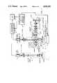
- apparatus in accordance with the present inventionis schematically shown to include a spotting microscope 10, a LINNIK microscope 12, an X,Y stage 14 for carrying a wafer 16 and a piezo-electric vertical motion system 18 between a set up position beneath microscope 10 and an inspection position beneath microscope 12, a pair of video cameras 20 and 22, data processing electronics 24, a CRT display 26 and an electronic controller and operator interface console 28.
- a light wave from a source 31 reaching the image plane 36is the sum of two constituent waves; one reflecting off the surface of the object 16, and the other reflecting off the surface of a reference mirror 34. Fringes are seen in the image at 36, even when white light is used to illuminate the object. If broad band illumination (white light) is used, strongest fringing occurs when the path difference between the reference channel 32 and the object channel 30 is very small, on the order of a fraction of the average wavelength, because the coherence length of white light is very short. When the degree of coherence is high between the reference channel and the object channel, the fringes are strong. Conversely, when the degree of coherence is low, the fringes are weak.
- white light Kohler illuminationis provided by a Xenon arc lamp 31, and a shutter 33 is included to flip the reference beam in and out.
- the fringe rate and directioncan be controlled on commercially available Linnik microscopes by moving the microscope objective in the reference channel off-axis. Accordingly, in the preferred embodiment the lens 35 is positioned to make the fringes which appear at image plane 36 be parallel to camera 22's raster direction and the fringe spacing equal to 32 horizontal raster rows of camera 22.
- the overall path length difference between the reference channel and the object channelcan be varied so as to introduce a phase difference between the object channel and the reference channel.
- the phase shiftwill be the same for all frequencies of the light.
- intensities at the image planeare of the form
- the illuminationis actually broad band and the phase shift is different for the different frequencies of the light.
- the following functional form for ⁇ U 1 *U 2 >is a good approximation for images taken in a two beam interference microscope:
- Equation (12)is still deriveable provided that is made to vary through 2 ⁇ by letting l vary from - ⁇ /K(l) to ⁇ /K(l) in the calculation of the variance.
- the parameter "m” in equation (13)is a complex constant.
- the technique of the present inventionis to synthetically construct images the brightness of which at each image point is proportional to C. This amounts to imaging by means of a coherence probe.
- the interference microscope 12is set up in the following way prior to calculation of C: With a first surface mirror (not shown) as the object (at 16), the focus in the object channel 30 and the reference channel 32 are adjusted so that both the reference mirror 34 and the object mirror are simultaneously in focus. Then the path difference is adjusted until the maximum degree of coherence is obtained between the object wave and the reference wave. This reference position is then the center point in the variation of path difference used to measure the degree of coherence.
- a window in the center of the image plane 36is selected as the area of interest, and after focusing the reference and object mirrors, the path is adjusted so that the fringe amplitude is the greatest at center of the window.
- the object mirroris then replaced by an object such as a silicon wafer 16 having an integrated circuit formed in its upper surface.
- the degree of coherence Ccan be measured in a Linnik microscope in several ways.
- One wayis to vary the path length of the reference channel 32; for example, through one or more wavelengths centered on the reference position, and while doing this, calculating electronically the oscillation in intensity at each point in the image plane of the microscope.
- the amplitude of oscillation (variance)is proportional to C.
- the interference fringesmay be adjusted so that they lie perpendicular to a line to be inspected.
- the fringe spacingmay also be adjusted to any convenient value. In this case C is simply the amplitude of the fringes within the window, i.e.,
- FIGS. 3-7show photographs of actual fringe data taken at the different object elevations generally depicted in FIG. 2.
- the object in this casewas a silicon wafer having a one micron high resist line 40 formed on its upper surface.
- the vertical and horizontal white lines depicted in the photographsare an electronic overlay produced on the display CRT 26 and can be ignored for this discussion.
- the resist portion 40is in the center of each photo, and as depicted in FIG. 2, the five photos of FIGS. 3-7 are taken at different positions of the object along the vertical (or Z) axis.
- the plane of focus of the image shown in FIG. 3is slightly above the top surface of the resist line 40, i.e., at level 5 in FIG. 2.
- the fringe intensityis shown to be weak.
- FIG. 4shows the wafer raised a few thousand Angstroms to bring the top of the resist into focus (at level 4 of FIG. 2).
- Fringes 43 in the window 42are now strong in the central portion of the image (corresponding to the top surface of the resist) but are weak on either side (where no resist is present).
- FIG. 5shows the wafer again raised an additional few thousand Angstroms so that the focal plane is between the top level of the resist and the silicon substrate (level 3 in FIG. 2).
- the fringesare weak in both the resist region and the silicon region since neither is in focus.
- the waferhas again been raised another few thousand Angstroms to level 2 to bring the silicon surface 44 (FIG. 2) into focus.
- the fringes 45are strong on the silicon and are fairly weak in the resist portion of the image.
- the process by which fringe amplitudes are used to measure line widths on integrated circuitsis shown in the flow chart of FIG. 8.
- the boxesdescribe the algorithms used.
- the "column in window” reference in FIG. 8refers to the columns of pixels, one of which is shown at 46 in FIG. 2, scanned by the processor 24 to determine the variance values over the length of the window 42, to thereby calculate the fringe coherence.
- the image 36is scanned by video camera 22, which develops an analog raster scan thereof for input to the processing electronics 24.
- the first processing stepis to convert the analog data into 8 bit digital form and to store the data in a computer memory.
- a "window"such as is illustrated at 42 in FIG. 2, is then scanned a pixel column at a time, as illustrated at 46 and the data corresponding to each column is moved by DMA transfer to a high speed arithmetic processor which calculates the variance of each columnar array and stores its RMS value in memory.
- the stageis incremented in the Z direction to another level, another scanning operation is completed and the data stored. This operation is repeated at levels separated by approximately 500 Angstroms until sufficient data is obtained to evaluate all desired surfaces.
- the several sets of scan data stored in memoryis then itself scanned at the centermost point X R in "X" of the resist line 40 (along the Z axis in FIG. 2) to determine the level having the highest RMS value, and such level is determined to coincide with and thus identify the top of the scanned line.
- FIG. 9One such electronic scan is depicted in FIG. 9 wherein the ordinate represents the RMS value of the central column data and the abscissa represents the inspection level (or stage position along the Z axis).
- the peak at level 4corresponds to the top of the resist line 40 of FIG. 2 while the peak at level 2 corresponds to reflection off the wafer substrate 44.
- the horizontal distance between the two peaksis thus an indication of the vertical thickness of the resist line 40.
- the memoryis thereafter scanned at an X position X s over only the substrate to find the scan line having the brightest level and this is taken to be the bottom of the line. By subtracting the top level from this bottom level information the height of the line can be determined.
- the constants A, B, and Care determined by calibration procedure. Once these widths are determined they can be reported to the CRT and displayed to the user.
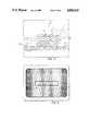
- FIG. 10shows an artist's rendition of the synthetic images produced on a CRT screen by imaging C.
- the upper and lower righthand quadrants 50 and 52show cross sections of the line, each row corresponding to a different level (scan line).
- the elevated resist 54appears as a cloud above the silicon substrate.
- An electronic line 56has been drawn in the right upper quadrant through the algorithm's choice as the best row to call the top of the line.
- the upper left hand quadrant 58shows this row expanded vertically to fill the entire quadrant and to thereby look like a top down view.
- the lower right hand quadrant 52showns a line 60 drawn through the algorithm's choice as the best candidate for the bottom substrate level.
- the lower left quadrant 62depicts an expanded top down view of the line 60.
- the edge finding algorithmthen uses a threshold technique to find the edges in both the upper and lower left hand quadrants.
- the heightis known (by the difference in stage position between the top and bottom rows)
- the top widthis known by the distance between the edges in the upper left quadrant
- the bottom widthis known by the distance between the edges in the bottom left quadrant
- the wall anglesmay be calculated.
- the techniqueconsists of first aligning a semiconductor IC line (such as 40 in FIG. 2) in the field of view of the spotting microscope 10.
- the waferis then moved a fixed offset to the right, as illustrated in FIG. 1, so that the same line is now viewed by the Linnik microscope 12.
- the interference fringesare then pre-adjusted to lie perpendicular to the line direction, and the fringe spacing is adjusted to have two complete fringes within the window (of variance calculation) 42 (FIGS. 3-7) when a reflective plane in the object is in focus (see FIG. 4 for example.
- the waferis then dropped in the z direction so that the highest point in the line is several thousand Angstroms below the focal plane, and the resulting image at 36 is digitized by the electronics 24.
- the fringe amplitudeis then calculated for each scan column 46 (FIG. 2) in the window 42, and the result is stored in memory.
- One method of calculating the fringe coherenceis to calculate the variance of each column array 46 (FIG. 2) across the window 42. To accomplish this for each array 46, the arithmetic processor in the electronics 24 calculates: ##EQU9##
- the stageis then moved up a small distance (about 500 Angstroms) and another image is digitized, fringe amplitudes calculated, and results stored.
- the process of moving the stage up, digitizing the image, and storing the fringe amplitudesis repeated until the stage has scanned a sufficient distance to place the lowest point of the line above the optics focal plane so that the entire depth of the line has been sectioned.
- top and bottom levels of the lineare then determined by finding the brightest scan rows at the appropriate positions in the image. Then the edges of the line at the top and bottom levels are determined by an edge finding algorithm. Finally, the output data is calculated by means of a calibration formula which calculates the top and bottom width by the formulas:
- a 1 , A 2 , B 1 , B 2 , C 1 and C 2are determined by a calibration procedure, and the results maybe reported to the CRT 26.
- the resultsconsist of the top width and bottom width, as well as the positions of the four edges used in the calculation of the vertical wall angles.
Landscapes
- Physics & Mathematics (AREA)
- General Physics & Mathematics (AREA)
- Biochemistry (AREA)
- General Health & Medical Sciences (AREA)
- Health & Medical Sciences (AREA)
- Life Sciences & Earth Sciences (AREA)
- Chemical & Material Sciences (AREA)
- Analytical Chemistry (AREA)
- Engineering & Computer Science (AREA)
- Signal Processing (AREA)
- Immunology (AREA)
- Pathology (AREA)
- Microscoopes, Condenser (AREA)
- Length Measuring Devices By Optical Means (AREA)
- Investigating Materials By The Use Of Optical Means Adapted For Particular Applications (AREA)
- Testing Or Measuring Of Semiconductors Or The Like (AREA)
Abstract
Description
1. Field of the Invention
The present invention relates generally to precision optical inspection methods and apparatus, and more particularly to a method and apparatus for performing microscopic inspection and measurement of integrated circuit wafer geometry using interference microscopy in combination with electronic image processing.
2. Discussion of the Prior Art
It has long been desired that means be provided to inspect and measure the characteristics of microminiature surfaces such as those formed in integrated circuit wafers. One such characteristic of interest is the line widths of the various traces produced on a wafer surface during IC device manufacture.
One prior art technique for integrated circuit metrology includes the use of an ordinary microscope with some form of electronic detector positioned at the image plane. For example, video cameras, scanning slits (see U.S. Pat. No. 4,373,817), shearing systems and linear arrays, have all been used as detectors with ordinary microscopes. However, the capability of the ordinary microscope is limited in that it can only measure the intensity of the optical wave amplitude and cannot measure the complex phase of the amplitude. As a consequence, the three-dimensional nature of integrated circuit surfaces makes use of the classical microscope impractical for precision surface inspections and measurements of this type.
Other prior art techniques have used confocal laser scanning microscopes to obtain three dimensional data relating to integrated circuit surfaces. A rather thorough treatment of the subject may be found in T. Wilson and C. Shepard (1984), Theory and Practice of Scanning Optical Microscopy, Academic Press.
Aside from the complexity and relatively high cost associated with the use of confocal laser devices and techniques, the fact that such techniques use monochromatic light makes them subject to inaccuracies caused by destructive interference for certain thicknesses of transparent films often found in semiconductor devices.
It is therefore a principal object of the present invention to provide an improved method and apparatus for accomplishing three dimensional inspection of integrated circuits and the like.
Another object of the present invention is to provide an improved synthetic imaging technique utilizing a two beam interference microscope.
Still another object of the present invention is to provide a method and apparatus by which the top width, bottom width and height of an integrated circuit line may be accurately measured.
Briefly, a preferred embodiment of the present invention includes a specially adapted Linnik microscope in combination with a video camera, a wafer transport stage and data processing electronics to form a novel inspection apparatus based on the use of the two beam interference microscope. The apparatus can utilize either broad band or narrow band light to develop a plurality of interference images taken at different axial positions relative to the surface under investigation. The point-by-point brightness along scan lines across such images is then used to develop data which is proportional to the degree of coherence (or to the fringe amplitude, the variance of the fringes, or the amplitude of oscillation of the fringes) as the optical path difference is varied in a two beam optical or acoustic microscope.
Among the advantages of the present invention are that it provides a much simpler and more economical technique than those using the confocal microscope.
Another advantage is that it can use white light rather than monochromatic light and as a result, can have a signal-to-noise ratio which is not degraded by coherent speckle effects which affect any coherent optical system. Moreover, by using white light the possibility of destructive interference for certain thicknesses of transparent films is eliminated.
Furthermore, the theoretical resolution along the optical axis appears to be better than that for a confocal microscope because the short coherence length of white light effectively reduces the depth of focus of the instrument. Empirically, it also appears that the present invention substantially improves the lateral resolution of the microscope, at least for the purpose of measuring linewidths of integrated circuits.
These and other objects and advantages of the present invention will no doubt become apparent to those skilled in the art after having read the following detailed description of the preferred embodiments which are illustrated in the several figures of the drawing.
FIG. 1 is a schematic diagram depicting the basic functional components of the present invention;
FIG. 2 is an isometric diagram illustrating an integrated circuit line and five inspection levels;
FIGS. 3 through 7 are actual photographic depictions of interference images taken at thelevels 5 through 1 respectively, of FIG. 2;
FIG. 8 is a flow diagram functionally depicting operation of the electronic processing electronics of the present invention;
FIG. 9 is an RMS profile of a central column developed in accordance with the present invention; and
FIG. 10 is a depiction of a CRT display in accordance with the present invention.
Interference microscopes can measure the topography of reflective surfaces using standard techniques so long as the undulations in relief are within the depth of field of the imaging system, and so long as the topography is not so jagged as to confuse the fringe counting algorithm. The basic formula is ##EQU1## where Δh is the difference in height between two points in the image, Δφ is the phase difference, and λ is the wave length of light. The standard applications of the Linnik microscope in this context are given in "Incident-Light Microscope Inteferometer for the Orthoplan and Metalloplan", Instruction Manual for Use of the Linnik Microscope Attachment by Ernst Leitz Gmbh, Wetzlar (1980); and in LEITZ, "Incident-Light Interference Illuminator for the Orthoplan/Metalloplan, a module which uses the wave length of light for measurement (19--)".
However, these standard techniques break down when any of the following three conditions are present:
1. The topographic fluctuations on the object surface within the field of view exceed the depth of focus of the microscope;
2. The object consists of transparent structures formed on an opaque substrate; or
3. The object surface has steep cliffs or walls the vertical extent of which exceeds a half wavelength of light.
When any of these cases occur, as they often do in integrated circuit devices, the standard use of the Linnik or other two beam interference microscopes simply does not give useful data because the fringe counting algorithm provides hopelessly confused and incorrect results when combined withequation 1.
The analysis process of the present invention described hereinafter overcomes the difficulties encountered by the standard techniques of Linnik interference microscopy, and when implemented in electronic hardware offers new capabilities for automated inspection of semiconductor devices.
The basic concept of the present invention is that broad band illumination (white light) has a very short coherence length, and by measuring the degree of coherence between an object and a reference beam at each point in an image, a powerful light sectioning technique may be developed.
The principle can be illustrated with scalar diffraction theory. However, the basic ideas apply in general even when scalar diffraction theory does not provide a good approximation.
Consider the wave equation of light in a homogeneous medium: ##EQU2## where c is the speed of light in the medium and u may be written as a Fourier integral in the form ##EQU3## The spectral density is ##EQU4## where α is a normalization constant and δ is a delta function. The degree of first order coherence is ##EQU5## where the brackets <> denote ensemble average. If the wave u is a sum of two constituent waves:
U=U.sub.1 +U.sub.2 (7)
then the degree of coherence between U1 and U2 may be defined analogously as ##EQU6##
Referring now to FIG. 1 of the drawing, apparatus in accordance with the present invention is schematically shown to include a spotting microscope 10, a LINNIK microscope 12, an X,Y stage 14 for carrying awafer 16 and a piezo-electricvertical motion system 18 between a set up position beneath microscope 10 and an inspection position beneath microscope 12, a pair ofvideo cameras 20 and 22,data processing electronics 24, aCRT display 26 and an electronic controller andoperator interface console 28.
In a two-beam interference microscope (such as the Linnik microscope), a light wave from asource 31 reaching theimage plane 36 is the sum of two constituent waves; one reflecting off the surface of theobject 16, and the other reflecting off the surface of a reference mirror 34. Fringes are seen in the image at 36, even when white light is used to illuminate the object. If broad band illumination (white light) is used, strongest fringing occurs when the path difference between thereference channel 32 and theobject channel 30 is very small, on the order of a fraction of the average wavelength, because the coherence length of white light is very short. When the degree of coherence is high between the reference channel and the object channel, the fringes are strong. Conversely, when the degree of coherence is low, the fringes are weak. In the preferred embodiment, white light Kohler illumination is provided by a Xenonarc lamp 31, and ashutter 33 is included to flip the reference beam in and out. The fringe rate and direction can be controlled on commercially available Linnik microscopes by moving the microscope objective in the reference channel off-axis. Accordingly, in the preferred embodiment the lens 35 is positioned to make the fringes which appear atimage plane 36 be parallel tocamera 22's raster direction and the fringe spacing equal to 32 horizontal raster rows ofcamera 22.
The connection between degree of coherence and fringe intensity may be described as follows where U1 is the object wave and U2 is the reference wave. At the image plane, the superposition of the object and the reference wave results in the light intensity
<|U.sub.1 +U.sub.2 |.sup.2 >=<|U.sub.1 |.sup.2 >+<|U.sub.2 |.sup.2 >+2R.sub.e <U.sub.1 *U.sub.2 > (9)
The overall path length difference between the reference channel and the object channel can be varied so as to introduce a phase difference between the object channel and the reference channel. In the narrow bandwidth approximation, the phase shift will be the same for all frequencies of the light. In this case, intensities at the image plane are of the form
<|U.sub.1 +e.sup.iφ U.sub.2 |.sup.2 >=<|U.sub.1 |.sup.2 >+<|U.sub.2 |.sup.2 >+2R.sub.e [e.sup.iφ <U.sub.1 *U.sub.2 >](10)
The variance in equation 10, calculated by letting φ vary from -π to π is easily found to be
Variance of <|U.sub.1 +U.sub.2 e.sup.iφ |.sup.2 >=2|<U.sub.i *U.sub.2 >|.sup.2 (11)
and therefore the degree of coherence may be expressed as ##EQU7##
In the present case, the illumination is actually broad band and the phase shift is different for the different frequencies of the light. However, in this case it is found that the following functional form for <U1 *U2 > is a good approximation for images taken in a two beam interference microscope:
<U.sub.1 *U.sub.2 >=me.sup.R(l) e.sup.ilK(l), l=path difference, (13)
where R(l) and K(l) are slowly varying over the distance 2π/K(l) and therefore equation (12) is still deriveable provided that is made to vary through 2π by letting l vary from -π/K(l) to π/K(l) in the calculation of the variance. The parameter "m" in equation (13) is a complex constant.
Therefore, one can define an easily measurable quantity C(x,t) which may be taken as a practical measure of the degree of coherence as ##EQU8##
If U1 and U2 are not coherent, then C=0. In general, assuming that R(l) and K(l) are slowly varying in equation (13), it can be shown that
C=(<|U1 |2 ><|U2 |2 >)1/2 G (15)
The technique of the present invention is to synthetically construct images the brightness of which at each image point is proportional to C. This amounts to imaging by means of a coherence probe.
The interference microscope 12 is set up in the following way prior to calculation of C: With a first surface mirror (not shown) as the object (at 16), the focus in theobject channel 30 and thereference channel 32 are adjusted so that both the reference mirror 34 and the object mirror are simultaneously in focus. Then the path difference is adjusted until the maximum degree of coherence is obtained between the object wave and the reference wave. This reference position is then the center point in the variation of path difference used to measure the degree of coherence.
If fringe data is being used, as described below the setup is a little different. In such case, a window in the center of theimage plane 36 is selected as the area of interest, and after focusing the reference and object mirrors, the path is adjusted so that the fringe amplitude is the greatest at center of the window. The object mirror is then replaced by an object such as asilicon wafer 16 having an integrated circuit formed in its upper surface.
All parts of the object surface which are at the same "level" as the surface of the reference mirror will now produce a scattered wave which is relatively coherent with respect to the reference wave, and those image points end up being bright in the final image at 36 (FIG. 1). The very brightest points are those where the object locally is a horizontally reflective surface because at those points the object wave and reference wave match is best. Parts of the object which are at a different level than the reference mirror appear dark. Sectioning can then be accomplished by moving thewafer 16 up or down to obtain successive images corresponding to respective object planes passing through thewafer 16, as illustrated in FIG. 2.
The degree of coherence C can be measured in a Linnik microscope in several ways. One way is to vary the path length of thereference channel 32; for example, through one or more wavelengths centered on the reference position, and while doing this, calculating electronically the oscillation in intensity at each point in the image plane of the microscope. The amplitude of oscillation (variance) is proportional to C.
Alternatively, for object surface features which do not vary too quickly in one direction (such as in the case of a semiconductor integrated circuit line) the interference fringes may be adjusted so that they lie perpendicular to a line to be inspected. The fringe spacing may also be adjusted to any convenient value. In this case C is simply the amplitude of the fringes within the window, i.e.,
C=Fringe Amplitude (16)
The advantage of this technique is that, as will be further explained below, only one image is required to make a measurement of C at all points across the line.
FIGS. 3-7 show photographs of actual fringe data taken at the different object elevations generally depicted in FIG. 2. The object in this case was a silicon wafer having a one micron high resistline 40 formed on its upper surface. The vertical and horizontal white lines depicted in the photographs are an electronic overlay produced on thedisplay CRT 26 and can be ignored for this discussion. The resistportion 40 is in the center of each photo, and as depicted in FIG. 2, the five photos of FIGS. 3-7 are taken at different positions of the object along the vertical (or Z) axis.
More specifically, the plane of focus of the image shown in FIG. 3 is slightly above the top surface of the resistline 40, i.e., atlevel 5 in FIG. 2. Within thecentral window 42, framed in black in the photos, the fringe intensity is shown to be weak.
FIG. 4 shows the wafer raised a few thousand Angstroms to bring the top of the resist into focus (at level 4 of FIG. 2).Fringes 43 in thewindow 42 are now strong in the central portion of the image (corresponding to the top surface of the resist) but are weak on either side (where no resist is present).
FIG. 5 shows the wafer again raised an additional few thousand Angstroms so that the focal plane is between the top level of the resist and the silicon substrate (level 3 in FIG. 2). Here again, the fringes are weak in both the resist region and the silicon region since neither is in focus.
In FIG. 6 the wafer has again been raised another few thousand Angstroms tolevel 2 to bring the silicon surface 44 (FIG. 2) into focus. Here thefringes 45 are strong on the silicon and are fairly weak in the resist portion of the image.
In FIG. 7, only the resist shows strong fringing due to the reflection of the light off the bottom of the resist layer.
The process by which fringe amplitudes are used to measure line widths on integrated circuits is shown in the flow chart of FIG. 8. The boxes describe the algorithms used. The "column in window" reference in FIG. 8 refers to the columns of pixels, one of which is shown at 46 in FIG. 2, scanned by theprocessor 24 to determine the variance values over the length of thewindow 42, to thereby calculate the fringe coherence.
More particularly, theimage 36 is scanned byvideo camera 22, which develops an analog raster scan thereof for input to theprocessing electronics 24. The first processing step is to convert the analog data into 8 bit digital form and to store the data in a computer memory. A "window" such as is illustrated at 42 in FIG. 2, is then scanned a pixel column at a time, as illustrated at 46 and the data corresponding to each column is moved by DMA transfer to a high speed arithmetic processor which calculates the variance of each columnar array and stores its RMS value in memory. After data is collected across thewindow 42 the stage is incremented in the Z direction to another level, another scanning operation is completed and the data stored. This operation is repeated at levels separated by approximately 500 Angstroms until sufficient data is obtained to evaluate all desired surfaces. The several sets of scan data stored in memory is then itself scanned at the centermost point XR in "X" of the resist line 40 (along the Z axis in FIG. 2) to determine the level having the highest RMS value, and such level is determined to coincide with and thus identify the top of the scanned line.
One such electronic scan is depicted in FIG. 9 wherein the ordinate represents the RMS value of the central column data and the abscissa represents the inspection level (or stage position along the Z axis). As illustrated, the peak at level 4 corresponds to the top of the resistline 40 of FIG. 2 while the peak atlevel 2 corresponds to reflection off thewafer substrate 44. The horizontal distance between the two peaks is thus an indication of the vertical thickness of the resistline 40.
The memory is thereafter scanned at an X position Xs over only the substrate to find the scan line having the brightest level and this is taken to be the bottom of the line. By subtracting the top level from this bottom level information the height of the line can be determined.
The next step is to apply an edge finding algorithm to the memory location corresponding to the top of the line in order to determine the raw top width. An edge finding algorithm is then applied to the memory location corresponding to the bottom of the line to determine the raw bottom width. The final results for top and bottom width are calculated from the formulas top width=A1 * raw top width+B1 * raw bottom width+C1 bottom width=A2 * raw top width+B2 * raw bottom width+C2.
The constants A, B, and C are determined by calibration procedure. Once these widths are determined they can be reported to the CRT and displayed to the user.
FIG. 10 shows an artist's rendition of the synthetic images produced on a CRT screen by imaging C. The upper and lowerrighthand quadrants electronic line 56 has been drawn in the right upper quadrant through the algorithm's choice as the best row to call the top of the line.
The upperleft hand quadrant 58 shows this row expanded vertically to fill the entire quadrant and to thereby look like a top down view. The lowerright hand quadrant 52 showns aline 60 drawn through the algorithm's choice as the best candidate for the bottom substrate level.
The lowerleft quadrant 62 depicts an expanded top down view of theline 60. The edge finding algorithm then uses a threshold technique to find the edges in both the upper and lower left hand quadrants.
In this way the height is known (by the difference in stage position between the top and bottom rows), the top width is known by the distance between the edges in the upper left quadrant, the bottom width is known by the distance between the edges in the bottom left quadrant, and the wall angles may be calculated. For best results, calibration to scanning electron microscope results are required.
In operation the technique consists of first aligning a semiconductor IC line (such as 40 in FIG. 2) in the field of view of the spotting microscope 10. The wafer is then moved a fixed offset to the right, as illustrated in FIG. 1, so that the same line is now viewed by the Linnik microscope 12. The interference fringes are then pre-adjusted to lie perpendicular to the line direction, and the fringe spacing is adjusted to have two complete fringes within the window (of variance calculation) 42 (FIGS. 3-7) when a reflective plane in the object is in focus (see FIG. 4 for example.
The wafer is then dropped in the z direction so that the highest point in the line is several thousand Angstroms below the focal plane, and the resulting image at 36 is digitized by theelectronics 24. The fringe amplitude is then calculated for each scan column 46 (FIG. 2) in thewindow 42, and the result is stored in memory.
One method of calculating the fringe coherence is to calculate the variance of each column array 46 (FIG. 2) across thewindow 42. To accomplish this for each array 46, the arithmetic processor in theelectronics 24 calculates: ##EQU9##
The stage is then moved up a small distance (about 500 Angstroms) and another image is digitized, fringe amplitudes calculated, and results stored. The process of moving the stage up, digitizing the image, and storing the fringe amplitudes is repeated until the stage has scanned a sufficient distance to place the lowest point of the line above the optics focal plane so that the entire depth of the line has been sectioned.
The top and bottom levels of the line are then determined by finding the brightest scan rows at the appropriate positions in the image. Then the edges of the line at the top and bottom levels are determined by an edge finding algorithm. Finally, the output data is calculated by means of a calibration formula which calculates the top and bottom width by the formulas:
Top width=A.sub.1 *(Raw top width)+B.sub.1 *(Raw bottom width )+C.sub.1
Bottom width=A.sub.2 *(Raw top width)+B.sub.2 *(Raw bottom width)+C.sub.2
where A1, A2, B1, B2, C1 and C2 are determined by a calibration procedure, and the results maybe reported to theCRT 26. The results consist of the top width and bottom width, as well as the positions of the four edges used in the calculation of the vertical wall angles.
Although the present invention has been illustrated in a preferred embodiment, it is anticipated that following a reading of this disclosure numerous alterations and modifications thereof will become apparent to those skilled in the art. It is therefore intended that the appended claims be interpretted as covering all such embodiments as fall within the true spirit and scope of the invention.
Claims (16)
1. A method of inspecting an object and generating synthetic image data comprising the steps of:
(a) using an interference optical system including an object channel and a reference channel for simultaneously inspecting an object and a reflective reference surface and developing a plurality of images formed by the interference between object wave energy passing from said object and through said object channel to an image plane and reference wave energy passing from said reference surface and through said reference channel to said image plane, each said image being formed in response to a change in position of either said object or said reference surface;
(b) determining for each image the absolute value of the degree of coherence between said object wave energy and said reference wave energy by calculating the variance along each column of an array of mxn pixels in said image plane, where m and n are integers, and generating absolute value coherence data corresponding to each said column; and
(c) using said absolute value coherence data to generate synthetic image data representative of a particular characteristic of said object, wherein the brightness of each pixel element of a synthetic image developed using said synthetic image data is proportional to said absolute value coherence data.
2. A process for generating synthetic image data representative of a cross-section of an at least partially reflective irregular surface of an object formed by a portion of a semiconductor wafer having an elongated strip of raised surface extending therethrough, comprising the steps of:
(a) illuminating the irregular object surface with light from a source of illumination;
(b) illuminating a reflective reference surface with light from said source of illumination, said reference surface being formed by an optically flat mirror;
(c) collecting object light reflected from said object surface and directing said object light along a first optical axis;
(d) collecting reference light reflected from said reference surface and directing said reference light along a second optical axis at least a portion of which is parallel to said first optical axis;
(e) focussing the light directed along said first and second optical axes to form a fringed image pattern resulting from interference of said object light and said reference light;
(f) orientating said wafer so that a selected scan line may be directed substantially orthogonal relative to the length of said elongated strip;
(g) inspecting said image pattern to develop a series of coherence data corresponding to the fringe amplitude at points along said scan line;
(h) incrementally changing the position of said object along said first optical axis, each time repeating steps (a) through (e) and (g);
(i) processing the plurality of series of coherence data to develop synthetic image data corresponding to a cross-sectional profile of said object surface taken in a plane including said selected scan lines;
(j) displaying said synthetic image data to visually depict a cross-sectional profile of said object surface taken in the plane including said scan lines; and
(k) determining the position of said object along said first optical axis at which the value of said coherence data corresponding to the crossing of a first particular scan line over said raised surface is at a maximum relative to the corresponding coherence data of the other scan lines and identifying this position as corresponding to the top surface of said strip.
3. A process as recited in claim 2, and further comprising the step of;
(l) detecting the width of the top of said raised surface by measuring the length of the portion of said first particular scan line over which said coherence data is at a maximum.
4. A process as recited in claim 3, and further comprising the steps of;
(m) determining the position of said object along said first optical axis when the value of said coherence data corresponding to the crossing of another particular scan line over portions of said surface other than said raised surface are at a maximum relative to the corresponding data of the other scanned lines; and
(n) determining the width of the base of said raised surface by measuring the separation between the portions of said other particular scan lines over which said data is at a maximum.
5. A process as recited in claim 4, and further comprising the step of:
(o) determining the height of said raised surface above the adjacent wafer surface by measuring the distance between the position at which the object is positioned along said first optical axis when the width of the top of said raised surface is detected and the position along said first optical axis when the width of the base of said raised surface is detected.
6. A process as recited in claim 5 and further comprising the step of;
(p) calculating the slopes of the side walls of said raised surface, in the plane including said scan lines, as a function of the height of the top of the raised surface above the base thereof and the difference in width of the top and the base along the corresponding scan lines.
7. A process as recited in claim 2, wherein said synthetic image data is developed by calculating the intensity of the interference fringes in said fringed image pattern and by calculating the local variance of the image intensity caused by the fringes.
8. A process as recited in claim 2, wherein said synthetic image data is generated by calculating the variance of the intensity of each pixel in the image plane as the path difference between the first and second optical paths is made to change.
9. A method of measuring certain dimensions of an elongated strip of raised surface formed on an object, such as a semiconductor wafer or photomask, using an interference optical system to develop images formed by interference between object wave energy passing from the object and through an object channel to an image plane and reference wave energy passing through a reference channel to the image plane, comprising the steps of:
(a) illuminating the object surface with light from a source of illumination;
(b) illuminating a reflective reference surface with light from said source of illumination;
(c) collecting object light reflected from said object surface and directed along a first optical axis through said object channel;
(d) collecting reference light reflected from said reference surface and directed along a second optical axis through said reference channel, said second optical axis having at least a portion thereof which is parallel to said first optical axis;
(e) focusing the light directed along said parallel portions of said first and second optical axes onto an image plane to form an interference image pattern resulting from interference of said object light and said reference light;
(f) inspecting the image pattern by detecting the light intensity at each pixel in an array of mxn pixels extending across the image of said strip to produce pixel data;
(g) scanning the pixel data and calculating therefrom coherence data representing the absolute value or magnitude of the complex degree of coherence of light incident upon said image plane and storing the calculated coherence data for subsequent reference;
(h) incrementally changing the position of said object along said first optical axis, each time repeating steps (a) through (g); and
(i) using the stored coherence data to generate data from which a synthetic image corresponding to a transverse cross-section of the measured strip may be developed.
10. A method as recited in claim 9 and further including the step of:
inspecting the stored coherence data to determine the height of the top surface of said strip relative to the adjacent surface of said object, such height being measured by determining a first position along said first optical axis at which maximum coherence occurs at a point in an array corresponding with said top surface, and by determining a second position along said first optical axis at which maximum coherence occurs at a point in an array corresponding with said adjacent surface, the measured height of said top surface being equal to the distance between said first position and said second position.
11. A method as recited in claim 10 and further comprising the step of determining the width of the top surface of said strip by applying an edge finding algorithm to coherence data taken from the image corresponding to said top surface.
12. A method as recited in claim 10 and further comprising the step of measuring the width of the bottom of the strip by applying an edge finding algorithm to coherence data taken from the image corresponding to said adjacent surface.
13. A method as recited in claim 9 wherein the step of calculating the absolute value or magnitude of the complex degree of coherence is accomplished by measuring the variance of the interference image along pixel columns of an mxn array inspected at each position of said object along said optical axis.
14. A method as recited in claim 9 wherein the step of calculating the absolute value or magnitude of the complex degree of coherence is accomplished by calculating the variance of the light intensity among corresponding pixels of the several image patterns inspected as the position of said object is changed along said first optical axis producing a change in the path difference between said object channel and said reference channel.
15. A method as recited in claim 9 wherein the step of calculating the absolute value or magnitude of the complex degree of coherence is accomplished by calculating the variance of the light intensity among corresponding pixels of the several image patterns inspected as the position of said reference mirror is changed along said second optical axis producing a change in the path difference between said object channel and said reference channel.
16. A method of inspecting an object and generating synthetic image data comprising the steps of:
(a) using an interference optical system including an object channel and a reference channel for simultaneously inspecting an object and a reflective reference surface and developing a plurality of images formed by the interference between object wave energy passing from said object and through said object channel to an image plane and reference wave energy passing from said reference surface and through said reference channel to said image plane, each said image being formed in response to a change in position of either said object or said reference surface
(b) determining for each image the absolute value of the degree of coherence between said object wave energy and said reference wave energy by calculating the variance in the intensity of each pixel over the said plurality of images and generating corresponding absolute value coherence data; and
(c) using said absolute value coherence data to generate synthetic image data representative of a particular characteristic of said object, wherein the brightness of each pixel element of a synthetic image developed using said synthetic image data is proportional to said absolute value coherence data.
Priority Applications (5)
| Application Number | Priority Date | Filing Date | Title |
|---|---|---|---|
| US06/860,308US4818110A (en) | 1986-05-06 | 1986-05-06 | Method and apparatus of using a two beam interference microscope for inspection of integrated circuits and the like |
| AT87106331TATE79669T1 (en) | 1986-05-06 | 1987-05-01 | METHOD AND APPARATUS USING A TWO-BEAM INTERFERENCE MICROSCOPE FOR INVESTIGATION OF INTEGRATED CIRCUITS AND LIKE. |
| DE8787106331TDE3781197T2 (en) | 1986-05-06 | 1987-05-01 | METHOD AND DEVICE WITH A TWO-RAY INTERFERENCE MICROSCOPE FOR EXAMINING INTEGRATED CIRCUITS AND THE LIKE. |
| EP87106331AEP0244781B1 (en) | 1986-05-06 | 1987-05-01 | Method and apparatus of using a two beam interference microscope for inspection of integrated circuits and the like |
| JP62109105AJPH0629692B2 (en) | 1986-05-06 | 1987-05-06 | Method for inspecting an object and generating composite video data and object inspection apparatus |
Applications Claiming Priority (1)
| Application Number | Priority Date | Filing Date | Title |
|---|---|---|---|
| US06/860,308US4818110A (en) | 1986-05-06 | 1986-05-06 | Method and apparatus of using a two beam interference microscope for inspection of integrated circuits and the like |
Publications (1)
| Publication Number | Publication Date |
|---|---|
| US4818110Atrue US4818110A (en) | 1989-04-04 |
Family
ID=25332924
Family Applications (1)
| Application Number | Title | Priority Date | Filing Date |
|---|---|---|---|
| US06/860,308Expired - LifetimeUS4818110A (en) | 1986-05-06 | 1986-05-06 | Method and apparatus of using a two beam interference microscope for inspection of integrated circuits and the like |
Country Status (5)
| Country | Link |
|---|---|
| US (1) | US4818110A (en) |
| EP (1) | EP0244781B1 (en) |
| JP (1) | JPH0629692B2 (en) |
| AT (1) | ATE79669T1 (en) |
| DE (1) | DE3781197T2 (en) |
Cited By (105)
| Publication number | Priority date | Publication date | Assignee | Title |
|---|---|---|---|---|
| US4931630A (en)* | 1989-04-04 | 1990-06-05 | Wyko Corporation | Apparatus and method for automatically focusing an interference microscope |
| US4939378A (en)* | 1988-02-12 | 1990-07-03 | Fabrique Nationale Herstal | Process for length measurement by means of a photosensitive network camera |
| WO1990007723A1 (en)* | 1988-12-24 | 1990-07-12 | Wild Leitz Gmbh | Spectromicroscope with photometer |
| US5042949A (en)* | 1989-03-17 | 1991-08-27 | Greenberg Jeffrey S | Optical profiler for films and substrates |
| USRE33774E (en)* | 1988-03-02 | 1991-12-24 | Wegu-Messtechnik Gmbh | Coordinate measuring and testing machine |
| US5077695A (en)* | 1989-11-13 | 1991-12-31 | Board Of Trustees Of The Leland Stanford Junior University | Near field scanning acoustic microscope and method |
| US5133601A (en)* | 1991-06-12 | 1992-07-28 | Wyko Corporation | Rough surface profiler and method |
| US5144150A (en)* | 1990-03-07 | 1992-09-01 | Matsushita Electric Industrial Co., Ltd. | Configuration measuring apparatus |
| US5204734A (en)* | 1991-06-12 | 1993-04-20 | Wyko Corporation | Rough surface profiler and method |
| US5375175A (en)* | 1992-03-06 | 1994-12-20 | The Board Of Trustees Of The Leland Stanford Junior University | Method and apparatus of measuring line structures with an optical microscope by data clustering and classification |
| US5398113A (en)* | 1993-02-08 | 1995-03-14 | Zygo Corporation | Method and apparatus for surface topography measurement by spatial-frequency analysis of interferograms |
| US5402234A (en)* | 1992-08-31 | 1995-03-28 | Zygo Corporation | Method and apparatus for the rapid acquisition of data in coherence scanning interferometry |
| US5438413A (en)* | 1993-03-03 | 1995-08-01 | Kla Instruments Corporation | Process for measuring overlay misregistration during semiconductor wafer fabrication |
| DE4404154A1 (en)* | 1994-02-10 | 1995-08-17 | Fraunhofer Ges Forschung | Method and device for optically examining a surface |
| US5455899A (en)* | 1992-12-31 | 1995-10-03 | International Business Machines Corporation | High speed image data processing circuit |
| WO1995031694A1 (en)* | 1994-05-16 | 1995-11-23 | Zygo Corporation | Improved phase shifting interferometer and method for surface topography measurement |
| DE4425178A1 (en)* | 1994-07-16 | 1996-01-18 | Fraunhofer Ges Forschung | Coating thickness gauge using white light interferometer |
| WO1996012981A1 (en)* | 1994-10-21 | 1996-05-02 | Kla Instruments Corporation | Autofocusing apparatus and method for high resolution microscope system |
| US5539517A (en)* | 1993-07-22 | 1996-07-23 | Numetrix Ltd. | Method for simultaneously measuring the spectral intensity as a function of wavelength of all the pixels of a two dimensional scene |
| US5539516A (en)* | 1994-04-29 | 1996-07-23 | International Business Machines Corporation | Scanning pulsed profilometer |
| US5631733A (en)* | 1995-01-20 | 1997-05-20 | Photon Dynamics, Inc. | Large area defect monitor tool for manufacture of clean surfaces |
| US5760901A (en)* | 1997-01-28 | 1998-06-02 | Zetetic Institute | Method and apparatus for confocal interference microscopy with background amplitude reduction and compensation |
| US5784164A (en)* | 1997-03-20 | 1998-07-21 | Zygo Corporation | Method and apparatus for automatically and simultaneously determining best focus and orientation of objects to be measured by broad-band interferometric means |
| US5801824A (en)* | 1996-11-25 | 1998-09-01 | Photon Dynamics, Inc. | Large area defect monitor tool for manufacture of clean surfaces |
| US5867604A (en)* | 1995-08-03 | 1999-02-02 | Ben-Levy; Meir | Imaging measurement system |
| US5923430A (en)* | 1993-06-17 | 1999-07-13 | Ultrapointe Corporation | Method for characterizing defects on semiconductor wafers |
| US5953124A (en)* | 1998-01-19 | 1999-09-14 | Zygo Corporation | Interferometric methods and systems using low coherence illumination |
| US5969273A (en)* | 1998-02-12 | 1999-10-19 | International Business Machines Corporation | Method and apparatus for critical dimension and tool resolution determination using edge width |
| US6148114A (en)* | 1996-11-27 | 2000-11-14 | Ultrapointe Corporation | Ring dilation and erosion techniques for digital image processing |
| US6172349B1 (en)* | 1997-03-31 | 2001-01-09 | Kla-Tencor Corporation | Autofocusing apparatus and method for high resolution microscope system |
| WO2002033350A1 (en)* | 2000-10-19 | 2002-04-25 | Q-Vis Limited | Surface profiler with vibration-damped horizontal reference surface |
| US20020103564A1 (en)* | 2000-09-20 | 2002-08-01 | John Fielden | Methods and systems for determining a composition and a thickness of a specimen |
| US20020107650A1 (en)* | 2000-09-20 | 2002-08-08 | Dan Wack | Methods and systems for determining a critical dimension and a presence of defects on a specimen |
| US20020106848A1 (en)* | 2000-09-20 | 2002-08-08 | Dan Wack | Methods and systems for determining a property of a specimen prior to, during, or subsequent to lithography |
| US6480285B1 (en) | 1997-01-28 | 2002-11-12 | Zetetic Institute | Multiple layer confocal interference microscopy using wavenumber domain reflectometry and background amplitude reduction and compensation |
| US20020186368A1 (en)* | 2001-06-08 | 2002-12-12 | Eliezer Rosengaus | Systems and methods for inspection of specimen surfaces |
| US20030002043A1 (en)* | 2001-04-10 | 2003-01-02 | Kla-Tencor Corporation | Periodic patterns and technique to control misalignment |
| US20030139838A1 (en)* | 2002-01-16 | 2003-07-24 | Marella Paul Frank | Systems and methods for closed loop defect reduction |
| US20030174876A1 (en)* | 1999-04-05 | 2003-09-18 | Applied Materials, Inc. | Local bias map using line width measurements |
| US6673637B2 (en) | 2000-09-20 | 2004-01-06 | Kla-Tencor Technologies | Methods and systems for determining a presence of macro defects and overlay of a specimen |
| US6694284B1 (en) | 2000-09-20 | 2004-02-17 | Kla-Tencor Technologies Corp. | Methods and systems for determining at least four properties of a specimen |
| US20040032581A1 (en)* | 2002-01-15 | 2004-02-19 | Mehrdad Nikoonahad | Systems and methods for inspection of specimen surfaces |
| US20040061867A1 (en)* | 2000-11-17 | 2004-04-01 | Arnaud Dubois | Method and device for high-speed interferential microscopic imaging of an object |
| US6721094B1 (en) | 2001-03-05 | 2004-04-13 | Sandia Corporation | Long working distance interference microscope |
| US20040085549A1 (en)* | 2000-12-29 | 2004-05-06 | Carl Smets | Method and an apparatus for measuring positions of contact elements of an electronic component |
| US20040085544A1 (en)* | 2002-09-09 | 2004-05-06 | De Groot Peter J. | Interferometry method for ellipsometry, reflectometry, and scatterometry measurements, including characterization of thin film structures |
| US20040090634A1 (en)* | 2001-12-05 | 2004-05-13 | Sanjeev Mathur | System and method for inspection using white light intererometry |
| US20040151369A1 (en)* | 2003-01-31 | 2004-08-05 | Sirona Dental Systems Gmbh | Method and system for imaging an object |
| US20040150832A1 (en)* | 2003-01-31 | 2004-08-05 | Michael Mermelstein | Method and apparatus for measuring motion |
| US20040169861A1 (en)* | 2002-12-05 | 2004-09-02 | Kla-Tenor Technologies Corporation | Apparatus and method for detecting overlay errors using scatterometry |
| US20040189999A1 (en)* | 2003-03-06 | 2004-09-30 | De Groot Peter J. | Profiling complex surface structures using scanning interferometry |
| US6812045B1 (en) | 2000-09-20 | 2004-11-02 | Kla-Tencor, Inc. | Methods and systems for determining a characteristic of a specimen prior to, during, or subsequent to ion implantation |
| US20050008218A1 (en)* | 1998-07-15 | 2005-01-13 | O'dell Jeffrey | Automated wafer defect inspection system and a process of performing such inspection |
| US20050036151A1 (en)* | 2002-01-25 | 2005-02-17 | Erich Gornick | Method and device for opically testing semiconductor elements |
| US20050057757A1 (en)* | 2003-09-15 | 2005-03-17 | Xavier Colonna De Lega | Low coherence grazing incidence interferometry systems and methods |
| US20050073692A1 (en)* | 2003-03-06 | 2005-04-07 | De Groot Peter J. | Profiling complex surface structures using scanning interferometry |
| US20050088663A1 (en)* | 2003-10-27 | 2005-04-28 | De Groot Peter J. | Scanning interferometry for thin film thickness and surface measurements |
| US6891627B1 (en) | 2000-09-20 | 2005-05-10 | Kla-Tencor Technologies Corp. | Methods and systems for determining a critical dimension and overlay of a specimen |
| US6919957B2 (en) | 2000-09-20 | 2005-07-19 | Kla-Tencor Technologies Corp. | Methods and systems for determining a critical dimension, a presence of defects, and a thin film characteristic of a specimen |
| US20050195398A1 (en)* | 2002-12-05 | 2005-09-08 | Kla-Tencor Technologies Corporation | Continuously varying offset mark and methods of determining overlay |
| US20050225769A1 (en)* | 2002-03-14 | 2005-10-13 | Bankhead Andrew D | Surface profiling apparatus |
| US20050237535A1 (en)* | 2004-04-22 | 2005-10-27 | Deck Leslie L | Vibration resistant interferometry |
| US6985232B2 (en) | 2003-03-13 | 2006-01-10 | Tokyo Electron Limited | Scatterometry by phase sensitive reflectometer |
| US20060012582A1 (en)* | 2004-07-15 | 2006-01-19 | De Lega Xavier C | Transparent film measurements |
| US20060018514A1 (en)* | 2002-11-27 | 2006-01-26 | Bankhead Andrew D | Surface profiling apparatus |
| US6999180B1 (en) | 2003-04-02 | 2006-02-14 | Kla-Tencor Technologies Corporation | Optical film topography and thickness measurement |
| US7061625B1 (en)* | 2002-09-27 | 2006-06-13 | Kla-Tencor Technologies Corporation | Method and apparatus using interferometric metrology for high aspect ratio inspection |
| US20060158657A1 (en)* | 2005-01-20 | 2006-07-20 | De Lega Xavier C | Interferometer for determining characteristics of an object surface, including processing and calibration |
| US20060176522A1 (en)* | 2005-02-09 | 2006-08-10 | Taylor Hobson Limited | Apparatus for and a method of determining a surface characteristic |
| US7095507B1 (en)* | 2002-09-27 | 2006-08-22 | Kla-Tencor Technologies Corporation | Method and apparatus using microscopic and interferometric based detection |
| US7106425B1 (en) | 2000-09-20 | 2006-09-12 | Kla-Tencor Technologies Corp. | Methods and systems for determining a presence of defects and a thin film characteristic of a specimen |
| US7130029B2 (en) | 2000-09-20 | 2006-10-31 | Kla-Tencor Technologies Corp. | Methods and systems for determining an adhesion characteristic and a thickness of a specimen |
| US20060262321A1 (en)* | 2005-05-19 | 2006-11-23 | De Groot Peter | Method and system for analyzing low-coherence interferometry signals for information about thin film structures |
| US20070046953A1 (en)* | 2003-03-06 | 2007-03-01 | De Groot Peter | Interferometer and method for measuring characteristics of optically unresolved surface features |
| US20070086013A1 (en)* | 2005-10-11 | 2007-04-19 | Zygo Corporation | Interferometry method and system including spectral decomposition |
| AU2002213638B2 (en)* | 2000-10-19 | 2007-08-30 | Customvis Plc | Surface profiler with vibration-damped horizontal reference surface |
| US20080018901A1 (en)* | 2006-07-21 | 2008-01-24 | Zygo Corporation | Compensation of systematic effects in low coherence interferometry |
| US20080049233A1 (en)* | 2002-09-09 | 2008-02-28 | Zygo Corporation | Multiple-Angle Multiple-Wavelength Interferometer Using High-NA Imaging and Spectral Analysis |
| US20080088849A1 (en)* | 2005-01-20 | 2008-04-17 | Zygo Corporation | Interferometry for determining characteristics of an object surface, with spatially coherent illumination |
| US20080174784A1 (en)* | 2006-12-22 | 2008-07-24 | Zygo Corporation | Apparatus and method for measuring characteristics of surface features |
| US20080180685A1 (en)* | 2007-01-31 | 2008-07-31 | Zygo Corporation | Interferometry for lateral metrology |
| DE102007010389A1 (en)* | 2007-03-03 | 2008-09-04 | Polytec Gmbh | Device for optical measurement of objects, has signal evaluation unit, and interferometer with light source and detectors, where light source is formed so that it generates light with coherence length smaller than one centimeter |
| US20080215271A1 (en)* | 2002-03-14 | 2008-09-04 | Taylor Hobson Limited | Surface profiling apparatus |
| US7430898B1 (en) | 2003-09-04 | 2008-10-07 | Kla-Tencor Technologies Corp. | Methods and systems for analyzing a specimen using atomic force microscopy profiling in combination with an optical technique |
| US20080266571A1 (en)* | 2006-10-27 | 2008-10-30 | Deck Leslie L | Vibration Resistant Interferometry |
| US20090021723A1 (en)* | 2007-07-19 | 2009-01-22 | Zygo Corporation | Generating model signals for interferometry |
| DE102007053124B3 (en)* | 2007-11-08 | 2009-01-29 | Carl Mahr Holding Gmbh | Compact Linnik interferometer |
| US7508974B2 (en) | 1998-01-16 | 2009-03-24 | Scanner Technologies Corporation | Electronic component products and method of manufacturing electronic component products |
| US20090128827A1 (en)* | 2007-11-13 | 2009-05-21 | De Groot Peter | Interferometer utilizing polarization scanning |
| US20090147268A1 (en)* | 2007-10-12 | 2009-06-11 | Zygo Corporation | Interferometric analysis of under-resolved features |
| US20090182528A1 (en)* | 2007-12-14 | 2009-07-16 | De Groot Peter | Analyzing surface structure using scanning interferometry |
| US20100128278A1 (en)* | 2008-11-26 | 2010-05-27 | Zygo Corporation | Fiber-based interferometer system for monitoring an imaging interferometer |
| US20100290061A1 (en)* | 2008-01-03 | 2010-11-18 | Industry-University Cooperation Foundation Sogang University | Scanning microscope using an i/q-interferometer |
| USRE45245E1 (en) | 2000-08-30 | 2014-11-18 | Kla-Tencor Corporation | Apparatus and methods for determining overlay of structures having rotational or mirror symmetry |
| US9164397B2 (en) | 2010-08-03 | 2015-10-20 | Kla-Tencor Corporation | Optics symmetrization for metrology |
| US9310186B2 (en) | 2012-04-23 | 2016-04-12 | Ben-Gurion University Of The Negev Research And Development Authority | True-spectroscopic dual mode high resolution full-field optical coherence tomography using liquid crystal devices |
| US20160131472A1 (en)* | 2014-11-10 | 2016-05-12 | Samsung Electronics Co., Ltd. | Optical measurement system and method for measuring critical dimension of nanostructure |
| US9395173B2 (en)* | 2014-10-22 | 2016-07-19 | National Applied Research Laboratories | Multi-functioned optical measurement device and method for optically measuring a plurality of parameters |
| US9645079B2 (en) | 2011-02-10 | 2017-05-09 | Kla-Tencor Corporation | Structured illumination for contrast enhancement in overlay metrology |
| US9927718B2 (en) | 2010-08-03 | 2018-03-27 | Kla-Tencor Corporation | Multi-layer overlay metrology target and complimentary overlay metrology measurement systems |
| US10451412B2 (en) | 2016-04-22 | 2019-10-22 | Kla-Tencor Corporation | Apparatus and methods for detecting overlay errors using scatterometry |
| US10890436B2 (en) | 2011-07-19 | 2021-01-12 | Kla Corporation | Overlay targets with orthogonal underlayer dummyfill |
| US20230324168A1 (en)* | 2022-03-22 | 2023-10-12 | Mitutoyo Corporation | Measurement method of surface shape and surface shape measurement device |
| US12023106B2 (en) | 2020-10-12 | 2024-07-02 | Johnson & Johnson Surgical Vision, Inc. | Virtual reality 3D eye-inspection by combining images from position-tracked optical visualization modalities |
| US12045957B2 (en) | 2020-10-21 | 2024-07-23 | Johnson & Johnson Surgical Vision, Inc. | Visualizing an organ using multiple imaging modalities combined and displayed in virtual reality |
Families Citing this family (16)
| Publication number | Priority date | Publication date | Assignee | Title |
|---|---|---|---|---|
| JPH061167B2 (en)* | 1988-05-17 | 1994-01-05 | 日本鋼管株式会社 | Measuring method and device for three-dimensional curved surface shape |
| US4957367A (en)* | 1988-05-31 | 1990-09-18 | Lev Dulman | Inteferometric imaging system |
| FR2640040B1 (en)* | 1988-12-05 | 1994-10-28 | Micro Controle | OPTICAL MEASUREMENT METHOD AND DEVICE |
| EP0532927B1 (en)* | 1991-08-22 | 1996-02-21 | Kla Instruments Corporation | Automated photomask inspection apparatus |
| DE19504189C2 (en)* | 1995-02-09 | 1998-03-19 | Leitz Messtechnik Gmbh | Interferometer device |
| DE19544253B4 (en)* | 1995-11-28 | 2006-06-29 | Jochen Neumann | Method for dispersion compensation in interferometers with non-symmetrical to the reference beam path ausgefehltem object beam path |
| JP4960336B2 (en)* | 2001-10-31 | 2012-06-27 | オリンパス株式会社 | Optical scanning observation device |
| EP1441215B1 (en)* | 2001-10-31 | 2012-08-01 | Olympus Corporation | Optical scanning type observation device |
| DE102004022341A1 (en)* | 2004-05-04 | 2005-12-29 | Carl Mahr Holding Gmbh | Device and method for combined interferometric and image-based geometry detection, especially in microsystem technology |
| DE102006021557B3 (en)* | 2006-05-08 | 2007-07-12 | Carl Mahr Holding Gmbh | Device under test reproducing and/or measuring arrangement for micro system technology, has illumination device illuminating device under test whose light is kept away from reference path |
| DE102007020860A1 (en)* | 2007-05-02 | 2008-11-13 | Carl Mahr Holding Gmbh | XY and angle measurement using combined white light interferometry |
| JP5547105B2 (en)* | 2011-02-01 | 2014-07-09 | 株式会社キーエンス | Dimension measuring apparatus, dimension measuring method and program for dimension measuring apparatus |
| US9816940B2 (en)* | 2015-01-21 | 2017-11-14 | Kla-Tencor Corporation | Wafer inspection with focus volumetric method |
| NL2016121A (en)* | 2015-02-06 | 2016-09-29 | Asml Netherlands Bv | A method and apparatus for improving measurement accuracy |
| KR102353287B1 (en)* | 2021-12-08 | 2022-01-19 | (주)에이피엠텍 | Risk monitoring system of steep slope topography with displacement measuring apparatus for structure |
| TWI863697B (en)* | 2023-11-10 | 2024-11-21 | 致茂電子股份有限公司 | An optimal diffuser position adjustment method for kohler illumination system |
Citations (3)
| Publication number | Priority date | Publication date | Assignee | Title |
|---|---|---|---|---|
| US4072422A (en)* | 1975-10-27 | 1978-02-07 | Canon Kabushiki Kaisha | Apparatus for interferometrically measuring the physical properties of test object |
| US4340306A (en)* | 1980-02-04 | 1982-07-20 | Balasubramanian N | Optical system for surface topography measurement |
| US4641971A (en)* | 1983-12-27 | 1987-02-10 | International Business Machines Corporation | White light interferometer |
Family Cites Families (6)
| Publication number | Priority date | Publication date | Assignee | Title |
|---|---|---|---|---|
| DE2128638A1 (en)* | 1971-06-09 | 1972-12-28 | Philips Patentverwaltung | Optical-interferometric method for the detection of errors in periodic image templates |
| GB1392448A (en)* | 1971-06-22 | 1975-04-30 | Nat Res Dev | Optical indpection |
| US3969577A (en)* | 1974-10-15 | 1976-07-13 | Westinghouse Electric Corporation | System for evaluating similar objects |
| GB1593284A (en)* | 1977-03-15 | 1981-07-15 | Nat Res Dev | Optical inspection |
| US4373817A (en)* | 1978-05-22 | 1983-02-15 | Nanometrics Incorporated | Computerized micromeasuring system and method therefor |
| US4513441A (en)* | 1983-08-02 | 1985-04-23 | Sparta, Inc. | Image comparison system |
- 1986
- 1986-05-06USUS06/860,308patent/US4818110A/ennot_activeExpired - Lifetime
- 1987
- 1987-05-01EPEP87106331Apatent/EP0244781B1/ennot_activeExpired - Lifetime
- 1987-05-01ATAT87106331Tpatent/ATE79669T1/ennot_activeIP Right Cessation
- 1987-05-01DEDE8787106331Tpatent/DE3781197T2/ennot_activeExpired - Lifetime
- 1987-05-06JPJP62109105Apatent/JPH0629692B2/ennot_activeExpired - Lifetime
Patent Citations (3)
| Publication number | Priority date | Publication date | Assignee | Title |
|---|---|---|---|---|
| US4072422A (en)* | 1975-10-27 | 1978-02-07 | Canon Kabushiki Kaisha | Apparatus for interferometrically measuring the physical properties of test object |
| US4340306A (en)* | 1980-02-04 | 1982-07-20 | Balasubramanian N | Optical system for surface topography measurement |
| US4641971A (en)* | 1983-12-27 | 1987-02-10 | International Business Machines Corporation | White light interferometer |
Non-Patent Citations (6)
| Title |
|---|
| Applied Optics, 11/1967, vol. 6, No. 11, "The Determination of the Absolute Contours of Optical Flats", by Primak, pp. 1917-1923. |
| Applied Optics, 11/1967, vol. 6, No. 11, The Determination of the Absolute Contours of Optical Flats , by Primak, pp. 1917 1923.* |
| Diamond, "Interfence Microscope for Testing Surfaces", Industrial Diamond Review, vol.-6, pp. 276-279, 9/46. |
| Diamond, Interfence Microscope for Testing Surfaces , Industrial Diamond Review, vol. 6, pp. 276 279, 9/46.* |
| Forman, "The Zygointerferometer System", Proc. SPIE, vol. 192, pp. 41-48, 1979. |
| Forman, The Zygointerferometer System , Proc. SPIE, vol. 192, pp. 41 48, 1979.* |
Cited By (274)
| Publication number | Priority date | Publication date | Assignee | Title |
|---|---|---|---|---|
| US4939378A (en)* | 1988-02-12 | 1990-07-03 | Fabrique Nationale Herstal | Process for length measurement by means of a photosensitive network camera |
| USRE33774E (en)* | 1988-03-02 | 1991-12-24 | Wegu-Messtechnik Gmbh | Coordinate measuring and testing machine |
| WO1990007723A1 (en)* | 1988-12-24 | 1990-07-12 | Wild Leitz Gmbh | Spectromicroscope with photometer |
| US5112125A (en)* | 1988-12-24 | 1992-05-12 | Wild Leitz, Gmbh | Spectral microscope with a photometer |
| US5042949A (en)* | 1989-03-17 | 1991-08-27 | Greenberg Jeffrey S | Optical profiler for films and substrates |
| US4931630A (en)* | 1989-04-04 | 1990-06-05 | Wyko Corporation | Apparatus and method for automatically focusing an interference microscope |
| US5077695A (en)* | 1989-11-13 | 1991-12-31 | Board Of Trustees Of The Leland Stanford Junior University | Near field scanning acoustic microscope and method |
| US5144150A (en)* | 1990-03-07 | 1992-09-01 | Matsushita Electric Industrial Co., Ltd. | Configuration measuring apparatus |
| US5204734A (en)* | 1991-06-12 | 1993-04-20 | Wyko Corporation | Rough surface profiler and method |
| US5355221A (en)* | 1991-06-12 | 1994-10-11 | Wyko Corporation | Rough surface profiler and method |
| US5133601A (en)* | 1991-06-12 | 1992-07-28 | Wyko Corporation | Rough surface profiler and method |
| US5375175A (en)* | 1992-03-06 | 1994-12-20 | The Board Of Trustees Of The Leland Stanford Junior University | Method and apparatus of measuring line structures with an optical microscope by data clustering and classification |
| US5402234A (en)* | 1992-08-31 | 1995-03-28 | Zygo Corporation | Method and apparatus for the rapid acquisition of data in coherence scanning interferometry |
| US5455899A (en)* | 1992-12-31 | 1995-10-03 | International Business Machines Corporation | High speed image data processing circuit |
| US5398113A (en)* | 1993-02-08 | 1995-03-14 | Zygo Corporation | Method and apparatus for surface topography measurement by spatial-frequency analysis of interferograms |
| US5438413A (en)* | 1993-03-03 | 1995-08-01 | Kla Instruments Corporation | Process for measuring overlay misregistration during semiconductor wafer fabrication |
| US7154605B2 (en) | 1993-06-17 | 2006-12-26 | Kla-Tencor Corporation | Method for characterizing defects on semiconductor wafers |
| US5923430A (en)* | 1993-06-17 | 1999-07-13 | Ultrapointe Corporation | Method for characterizing defects on semiconductor wafers |
| US7384806B2 (en) | 1993-06-17 | 2008-06-10 | Kla-Tencor Corporation | Method for characterizing defects on semiconductor wafers |
| US6661515B2 (en) | 1993-06-17 | 2003-12-09 | Kla-Tencor Corporation | Method for characterizing defects on semiconductor wafers |
| US6288782B1 (en) | 1993-06-17 | 2001-09-11 | Ultrapointe Corporation | Method for characterizing defects on semiconductor wafers |
| US20070104357A1 (en)* | 1993-06-17 | 2007-05-10 | Kla-Tencor Corporation | Method for Characterizing Defects on Semiconductor Wafers |
| US20030203520A1 (en)* | 1993-06-17 | 2003-10-30 | Worster Bruce W. | Method for characterizing defects on semiconductor wafers |
| US5539517A (en)* | 1993-07-22 | 1996-07-23 | Numetrix Ltd. | Method for simultaneously measuring the spectral intensity as a function of wavelength of all the pixels of a two dimensional scene |
| DE4404154A1 (en)* | 1994-02-10 | 1995-08-17 | Fraunhofer Ges Forschung | Method and device for optically examining a surface |
| US5539516A (en)* | 1994-04-29 | 1996-07-23 | International Business Machines Corporation | Scanning pulsed profilometer |
| WO1995031694A1 (en)* | 1994-05-16 | 1995-11-23 | Zygo Corporation | Improved phase shifting interferometer and method for surface topography measurement |
| DE4425178A1 (en)* | 1994-07-16 | 1996-01-18 | Fraunhofer Ges Forschung | Coating thickness gauge using white light interferometer |
| WO1996012981A1 (en)* | 1994-10-21 | 1996-05-02 | Kla Instruments Corporation | Autofocusing apparatus and method for high resolution microscope system |
| US5631733A (en)* | 1995-01-20 | 1997-05-20 | Photon Dynamics, Inc. | Large area defect monitor tool for manufacture of clean surfaces |
| US5867604A (en)* | 1995-08-03 | 1999-02-02 | Ben-Levy; Meir | Imaging measurement system |
| US5801824A (en)* | 1996-11-25 | 1998-09-01 | Photon Dynamics, Inc. | Large area defect monitor tool for manufacture of clean surfaces |
| US6148114A (en)* | 1996-11-27 | 2000-11-14 | Ultrapointe Corporation | Ring dilation and erosion techniques for digital image processing |
| US5760901A (en)* | 1997-01-28 | 1998-06-02 | Zetetic Institute | Method and apparatus for confocal interference microscopy with background amplitude reduction and compensation |
| US6091496A (en)* | 1997-01-28 | 2000-07-18 | Zetetic Institute | Multiple layer, multiple track optical disk access by confocal interference microscopy using wavenumber domain reflectometry and background amplitude reduction and compensation |
| US6480285B1 (en) | 1997-01-28 | 2002-11-12 | Zetetic Institute | Multiple layer confocal interference microscopy using wavenumber domain reflectometry and background amplitude reduction and compensation |
| US5784164A (en)* | 1997-03-20 | 1998-07-21 | Zygo Corporation | Method and apparatus for automatically and simultaneously determining best focus and orientation of objects to be measured by broad-band interferometric means |
| US6172349B1 (en)* | 1997-03-31 | 2001-01-09 | Kla-Tencor Corporation | Autofocusing apparatus and method for high resolution microscope system |
| US7508974B2 (en) | 1998-01-16 | 2009-03-24 | Scanner Technologies Corporation | Electronic component products and method of manufacturing electronic component products |
| US5953124A (en)* | 1998-01-19 | 1999-09-14 | Zygo Corporation | Interferometric methods and systems using low coherence illumination |
| US5969273A (en)* | 1998-02-12 | 1999-10-19 | International Business Machines Corporation | Method and apparatus for critical dimension and tool resolution determination using edge width |
| US20100239157A1 (en)* | 1998-07-15 | 2010-09-23 | Rudolph Technologies, Inc. | Automated wafer defect inspection system and a process of performing such inspection |
| US7729528B2 (en) | 1998-07-15 | 2010-06-01 | Rudolph Technologies, Inc. | Automated wafer defect inspection system and a process of performing such inspection |
| US20050008218A1 (en)* | 1998-07-15 | 2005-01-13 | O'dell Jeffrey | Automated wafer defect inspection system and a process of performing such inspection |
| US9337071B2 (en) | 1998-07-15 | 2016-05-10 | Rudolph Technologies, Inc. | Automated wafer defect inspection system and a process of performing such inspection |
| US9464992B2 (en) | 1998-07-15 | 2016-10-11 | Rudolph Technologies, Inc. | Automated wafer defect inspection system and a process of performing such inspection |
| US7133549B2 (en) | 1999-04-05 | 2006-11-07 | Applied Materials, Inc. | Local bias map using line width measurements |
| US20060251317A1 (en)* | 1999-04-05 | 2006-11-09 | Applied Materials, Inc. | Local bias map using line width measurements |
| US20030174876A1 (en)* | 1999-04-05 | 2003-09-18 | Applied Materials, Inc. | Local bias map using line width measurements |
| US7486814B2 (en) | 1999-04-05 | 2009-02-03 | Applied Materials, Inc. | Local bias map using line width measurements |
| USRE45245E1 (en) | 2000-08-30 | 2014-11-18 | Kla-Tencor Corporation | Apparatus and methods for determining overlay of structures having rotational or mirror symmetry |
| US9702693B2 (en) | 2000-08-30 | 2017-07-11 | Kla-Tencor Corporation | Apparatus for measuring overlay errors |
| US9182680B2 (en) | 2000-08-30 | 2015-11-10 | Kla-Tencor Corporation | Apparatus and methods for determining overlay of structures having rotational or mirror symmetry |
| US9347879B2 (en) | 2000-08-30 | 2016-05-24 | Kla-Tencor Corporation | Apparatus and methods for detecting overlay errors using scatterometry |
| US6829559B2 (en) | 2000-09-20 | 2004-12-07 | K.L.A.-Tencor Technologies | Methods and systems for determining a presence of macro and micro defects on a specimen |
| US7006235B2 (en) | 2000-09-20 | 2006-02-28 | Kla-Tencor Technologies Corp. | Methods and systems for determining overlay and flatness of a specimen |
| US7139083B2 (en) | 2000-09-20 | 2006-11-21 | Kla-Tencor Technologies Corp. | Methods and systems for determining a composition and a thickness of a specimen |
| US20020190207A1 (en)* | 2000-09-20 | 2002-12-19 | Ady Levy | Methods and systems for determining a characteristic of micro defects on a specimen |
| US7349090B2 (en) | 2000-09-20 | 2008-03-25 | Kla-Tencor Technologies Corp. | Methods and systems for determining a property of a specimen prior to, during, or subsequent to lithography |
| US7130029B2 (en) | 2000-09-20 | 2006-10-31 | Kla-Tencor Technologies Corp. | Methods and systems for determining an adhesion characteristic and a thickness of a specimen |
| US20040092045A1 (en)* | 2000-09-20 | 2004-05-13 | Gary Bultman | Methods and systems for determining a presence of macro and micro defects on a specimen |
| US20040115843A1 (en)* | 2000-09-20 | 2004-06-17 | Kla-Tencor, Inc. | Methods and systems for determining a presence of macro defects and overlay of a specimen |
| US7106425B1 (en) | 2000-09-20 | 2006-09-12 | Kla-Tencor Technologies Corp. | Methods and systems for determining a presence of defects and a thin film characteristic of a specimen |
| US7196782B2 (en) | 2000-09-20 | 2007-03-27 | Kla-Tencor Technologies Corp. | Methods and systems for determining a thin film characteristic and an electrical property of a specimen |
| US6782337B2 (en) | 2000-09-20 | 2004-08-24 | Kla-Tencor Technologies Corp. | Methods and systems for determining a critical dimension an a presence of defects on a specimen |
| US20030011786A1 (en)* | 2000-09-20 | 2003-01-16 | Ady Levy | Methods and systems for determining overlay and flatness of a specimen |
| US7751046B2 (en) | 2000-09-20 | 2010-07-06 | Kla-Tencor Technologies Corp. | Methods and systems for determining a critical dimension and overlay of a specimen |
| US6806951B2 (en) | 2000-09-20 | 2004-10-19 | Kla-Tencor Technologies Corp. | Methods and systems for determining at least one characteristic of defects on at least two sides of a specimen |
| US6812045B1 (en) | 2000-09-20 | 2004-11-02 | Kla-Tencor, Inc. | Methods and systems for determining a characteristic of a specimen prior to, during, or subsequent to ion implantation |
| US6818459B2 (en) | 2000-09-20 | 2004-11-16 | Kla-Tencor Technologies Corp. | Methods and systems for determining a presence of macro defects and overlay of a specimen |
| US20020179867A1 (en)* | 2000-09-20 | 2002-12-05 | John Fielden | Methods and systems for determining flatness, a presence of defects, and a thin film characteristic of a specimen |
| US20040073398A1 (en)* | 2000-09-20 | 2004-04-15 | Kla-Tencor, Inc. | Methods and systems for determining a critical dimension and a thin film characteristic of a specimen |
| US20020106848A1 (en)* | 2000-09-20 | 2002-08-08 | Dan Wack | Methods and systems for determining a property of a specimen prior to, during, or subsequent to lithography |
| US20020107650A1 (en)* | 2000-09-20 | 2002-08-08 | Dan Wack | Methods and systems for determining a critical dimension and a presence of defects on a specimen |
| US8179530B2 (en) | 2000-09-20 | 2012-05-15 | Kla-Tencor Technologies Corp. | Methods and systems for determining a critical dimension and overlay of a specimen |
| US8502979B2 (en) | 2000-09-20 | 2013-08-06 | Kla-Tencor Technologies Corp. | Methods and systems for determining a critical dimension and overlay of a specimen |
| US6950196B2 (en) | 2000-09-20 | 2005-09-27 | Kla-Tencor Technologies Corp. | Methods and systems for determining a thickness of a structure on a specimen and at least one additional property of the specimen |
| US6946394B2 (en) | 2000-09-20 | 2005-09-20 | Kla-Tencor Technologies | Methods and systems for determining a characteristic of a layer formed on a specimen by a deposition process |
| US20020103564A1 (en)* | 2000-09-20 | 2002-08-01 | John Fielden | Methods and systems for determining a composition and a thickness of a specimen |
| US6694284B1 (en) | 2000-09-20 | 2004-02-17 | Kla-Tencor Technologies Corp. | Methods and systems for determining at least four properties of a specimen |
| US6919957B2 (en) | 2000-09-20 | 2005-07-19 | Kla-Tencor Technologies Corp. | Methods and systems for determining a critical dimension, a presence of defects, and a thin film characteristic of a specimen |
| US6673637B2 (en) | 2000-09-20 | 2004-01-06 | Kla-Tencor Technologies | Methods and systems for determining a presence of macro defects and overlay of a specimen |
| US6917419B2 (en) | 2000-09-20 | 2005-07-12 | Kla-Tencor Technologies Corp. | Methods and systems for determining flatness, a presence of defects, and a thin film characteristic of a specimen |
| US6633831B2 (en) | 2000-09-20 | 2003-10-14 | Kla Tencor Technologies | Methods and systems for determining a critical dimension and a thin film characteristic of a specimen |
| US6917433B2 (en) | 2000-09-20 | 2005-07-12 | Kla-Tencor Technologies Corp. | Methods and systems for determining a property of a specimen prior to, during, or subsequent to an etch process |
| US7460981B2 (en) | 2000-09-20 | 2008-12-02 | Kla-Tencor Technologies Corp. | Methods and systems for determining a presence of macro and micro defects on a specimen |
| US6891627B1 (en) | 2000-09-20 | 2005-05-10 | Kla-Tencor Technologies Corp. | Methods and systems for determining a critical dimension and overlay of a specimen |
| US6891610B2 (en) | 2000-09-20 | 2005-05-10 | Kla-Tencor Technologies Corp. | Methods and systems for determining an implant characteristic and a presence of defects on a specimen |
| US20040080756A1 (en)* | 2000-10-19 | 2004-04-29 | Reid Phillip George | Surface profiler with vibration-damped horizontal reference surface |
| WO2002033350A1 (en)* | 2000-10-19 | 2002-04-25 | Q-Vis Limited | Surface profiler with vibration-damped horizontal reference surface |
| AU2002213638B2 (en)* | 2000-10-19 | 2007-08-30 | Customvis Plc | Surface profiler with vibration-damped horizontal reference surface |
| US6940602B2 (en)* | 2000-11-17 | 2005-09-06 | Centre National De La Recherche Scientific (C.N.R.S.) | Method and device for high-speed interferential microscopic imaging of an object |
| US20040061867A1 (en)* | 2000-11-17 | 2004-04-01 | Arnaud Dubois | Method and device for high-speed interferential microscopic imaging of an object |
| US20040085549A1 (en)* | 2000-12-29 | 2004-05-06 | Carl Smets | Method and an apparatus for measuring positions of contact elements of an electronic component |
| US7423743B2 (en) | 2000-12-29 | 2008-09-09 | Icos Vision Systems Nv | Method and an apparatus for measuring positions of contact elements of an electronic component |
| US6721094B1 (en) | 2001-03-05 | 2004-04-13 | Sandia Corporation | Long working distance interference microscope |
| US9476698B2 (en) | 2001-04-10 | 2016-10-25 | Kla-Tencor Corporation | Periodic patterns and technique to control misalignment between two layers |
| US20030002043A1 (en)* | 2001-04-10 | 2003-01-02 | Kla-Tencor Corporation | Periodic patterns and technique to control misalignment |
| US20050208685A1 (en)* | 2001-04-10 | 2005-09-22 | Ibrahim Abdulhalim | Periodic patterns and technique to control misalignment |
| US9234745B2 (en) | 2001-04-10 | 2016-01-12 | Kla-Tencor Corporation | Periodic patterns and techniques to control misalignment between two layers |
| US20040061857A1 (en)* | 2001-04-10 | 2004-04-01 | Ibrahim Abdulhalim | Periodic patterns and technique to control misalignment between two layers |
| US20090231584A1 (en)* | 2001-04-10 | 2009-09-17 | Kla-Tencor Technology Corporation | Periodic patterns and technique to control misaligment between two layers |
| US8570515B2 (en) | 2001-04-10 | 2013-10-29 | Kla-Tencor Corporation | Periodic patterns and technique to control misalignment between two layers |
| US20050157297A1 (en)* | 2001-04-10 | 2005-07-21 | Ibrahim Abdulhalim | Periodic patterns and technique to control misalignment between two layers |
| US7656528B2 (en) | 2001-04-10 | 2010-02-02 | Kla-Tencor Corporation | Periodic patterns and technique to control misalignment between two layers |
| US9835447B2 (en) | 2001-04-10 | 2017-12-05 | Kla-Tencor Corporation | Periodic patterns and technique to control misalignment between two layers |
| US20060262326A1 (en)* | 2001-04-10 | 2006-11-23 | Ibrahim Abdulhalim | Periodic patterns and technique to control misalignment between two layers |
| US20060065625A1 (en)* | 2001-04-10 | 2006-03-30 | Ibrahim Abdulhalim | Periodic patterns and technique to control misalignment between two layers |
| US9103662B2 (en) | 2001-04-10 | 2015-08-11 | Kla-Tencor Corporation | Periodic patterns and technique to control misalignment between two layers |
| US20060132807A1 (en)* | 2001-04-10 | 2006-06-22 | Ibrahim Abdulhalim | Periodic patterns and technique to control misalignment between two layers |
| US10151584B2 (en) | 2001-04-10 | 2018-12-11 | Kla-Tencor Corporation | Periodic patterns and technique to control misalignment between two layers |
| US20040229471A1 (en)* | 2001-04-10 | 2004-11-18 | Ibrahim Abdulhalim | Periodic patterns and technique to control misalignment between two layers |
| US8525994B2 (en) | 2001-04-10 | 2013-09-03 | Kla-Tencor Corporation | Periodic patterns and technique to control misaligment between two layers |
| US7072034B2 (en) | 2001-06-08 | 2006-07-04 | Kla-Tencor Corporation | Systems and methods for inspection of specimen surfaces |
| US20020186368A1 (en)* | 2001-06-08 | 2002-12-12 | Eliezer Rosengaus | Systems and methods for inspection of specimen surfaces |
| US20040090634A1 (en)* | 2001-12-05 | 2004-05-13 | Sanjeev Mathur | System and method for inspection using white light intererometry |
| US7158235B2 (en)* | 2001-12-05 | 2007-01-02 | Rudolph Technologies, Inc. | System and method for inspection using white light interferometry |
| US20040032581A1 (en)* | 2002-01-15 | 2004-02-19 | Mehrdad Nikoonahad | Systems and methods for inspection of specimen surfaces |
| US20030139838A1 (en)* | 2002-01-16 | 2003-07-24 | Marella Paul Frank | Systems and methods for closed loop defect reduction |
| US7236847B2 (en) | 2002-01-16 | 2007-06-26 | Kla-Tencor Technologies Corp. | Systems and methods for closed loop defect reduction |
| US20050036151A1 (en)* | 2002-01-25 | 2005-02-17 | Erich Gornick | Method and device for opically testing semiconductor elements |
| US7385707B2 (en) | 2002-03-14 | 2008-06-10 | Taylor Hobson Limited | Surface profiling apparatus |
| US20080215271A1 (en)* | 2002-03-14 | 2008-09-04 | Taylor Hobson Limited | Surface profiling apparatus |
| US7948634B2 (en) | 2002-03-14 | 2011-05-24 | Taylor Hobson Limited | Surface profiling apparatus |
| US20050225769A1 (en)* | 2002-03-14 | 2005-10-13 | Bankhead Andrew D | Surface profiling apparatus |
| US7869057B2 (en) | 2002-09-09 | 2011-01-11 | Zygo Corporation | Multiple-angle multiple-wavelength interferometer using high-NA imaging and spectral analysis |
| US20090015844A1 (en)* | 2002-09-09 | 2009-01-15 | De Groot Peter J | Interferometry Method for Ellipsometry, Reflectometry, and Scatterometry Measurements, Including Characterization of Thin Film Structures |
| US20080049233A1 (en)* | 2002-09-09 | 2008-02-28 | Zygo Corporation | Multiple-Angle Multiple-Wavelength Interferometer Using High-NA Imaging and Spectral Analysis |
| US20040085544A1 (en)* | 2002-09-09 | 2004-05-06 | De Groot Peter J. | Interferometry method for ellipsometry, reflectometry, and scatterometry measurements, including characterization of thin film structures |
| US7315382B2 (en) | 2002-09-09 | 2008-01-01 | Zygo Corporation | Interferometry method for ellipsometry, reflectometry, and scatterometry measurements, including characterization of thin film structures |
| US20070081167A1 (en)* | 2002-09-09 | 2007-04-12 | De Groot Peter J | Interferometry method for ellipsometry, reflectometry, and scatterometry measurements, including characterization of thin film structures |
| US7403289B2 (en)* | 2002-09-09 | 2008-07-22 | Zygo Corporation | Interferometry method for ellipsometry, reflectometry, and scatterometry measurements, including characterization of thin film structures |
| US20070247637A1 (en)* | 2002-09-09 | 2007-10-25 | De Groot Peter J | Interferometry Method for Ellipsometry, Reflectometry, and Scatterometry Measurements, Including Characterization of Thin Film Structures |
| US7812963B2 (en) | 2002-09-09 | 2010-10-12 | Zygo Corporation | Interferometry method for ellipsometry, reflectometry, and scatterometry measurements, including characterization of thin film structures |
| US7139081B2 (en)* | 2002-09-09 | 2006-11-21 | Zygo Corporation | Interferometry method for ellipsometry, reflectometry, and scatterometry measurements, including characterization of thin film structures |
| US7061625B1 (en)* | 2002-09-27 | 2006-06-13 | Kla-Tencor Technologies Corporation | Method and apparatus using interferometric metrology for high aspect ratio inspection |
| US7095507B1 (en)* | 2002-09-27 | 2006-08-22 | Kla-Tencor Technologies Corporation | Method and apparatus using microscopic and interferometric based detection |
| US20060018514A1 (en)* | 2002-11-27 | 2006-01-26 | Bankhead Andrew D | Surface profiling apparatus |
| US7518733B2 (en) | 2002-11-27 | 2009-04-14 | Taylor Hobson Limited | Surface profiling apparatus |
| US20080024766A1 (en)* | 2002-12-05 | 2008-01-31 | Kla-Tencor Technologies Corporation | Apparatus and methods for detecting overlay errors using scatterometry |
| US20080094630A1 (en)* | 2002-12-05 | 2008-04-24 | Kla-Tencor Technologies Corporation | Apparatus and methods for detecting overlay errors using scatterometry |
| US20080049226A1 (en)* | 2002-12-05 | 2008-02-28 | Kla-Tencor Technologies Corporation | Apparatus and methods for detecting overlay errors using scatterometry |
| US7663753B2 (en) | 2002-12-05 | 2010-02-16 | Kla-Tencor Technologies Corporation | Apparatus and methods for detecting overlay errors using scatterometry |
| US7440105B2 (en) | 2002-12-05 | 2008-10-21 | Kla-Tencor Technologies Corporation | Continuously varying offset mark and methods of determining overlay |
| US7433040B2 (en) | 2002-12-05 | 2008-10-07 | Kla-Tencor Technologies Corp. | Apparatus and methods for detecting overlay errors using scatterometry |
| US7933016B2 (en) | 2002-12-05 | 2011-04-26 | Kla-Tencor Technologies Corporation | Apparatus and methods for detecting overlay errors using scatterometry |
| US20040169861A1 (en)* | 2002-12-05 | 2004-09-02 | Kla-Tenor Technologies Corporation | Apparatus and method for detecting overlay errors using scatterometry |
| US7564557B2 (en) | 2002-12-05 | 2009-07-21 | Kla-Tencor Technologies Corp. | Apparatus and methods for detecting overlay errors using scatterometry |
| US7876440B2 (en) | 2002-12-05 | 2011-01-25 | Kla-Tencor Technologies Corporation | Apparatus and methods for detecting overlay errors using scatterometry |
| US20100091284A1 (en)* | 2002-12-05 | 2010-04-15 | Kla-Tencor Technologies Corporation | Apparatus and methods for detecting overlay errors using scatterometry |
| US7317531B2 (en) | 2002-12-05 | 2008-01-08 | Kla-Tencor Technologies Corporation | Apparatus and methods for detecting overlay errors using scatterometry |
| US20050195398A1 (en)* | 2002-12-05 | 2005-09-08 | Kla-Tencor Technologies Corporation | Continuously varying offset mark and methods of determining overlay |
| US20040151369A1 (en)* | 2003-01-31 | 2004-08-05 | Sirona Dental Systems Gmbh | Method and system for imaging an object |
| US20040150832A1 (en)* | 2003-01-31 | 2004-08-05 | Michael Mermelstein | Method and apparatus for measuring motion |
| US6906806B2 (en) | 2003-01-31 | 2005-06-14 | Michael Mermelstein | Method and apparatus for measuring motion |
| US7522764B2 (en)* | 2003-01-31 | 2009-04-21 | Sirona Dental Systems Gmbh | Method and system for imaging an object |
| US7242477B2 (en) | 2003-02-22 | 2007-07-10 | Kla-Tencor Technologies Corporation | Apparatus and methods for detecting overlay errors using scatterometry |
| US7280212B2 (en) | 2003-02-22 | 2007-10-09 | Kla-Tencor Technologies Corporation | Apparatus and methods for detecting overlay errors using scatterometry |
| US7289213B2 (en) | 2003-02-22 | 2007-10-30 | Kla-Tencor Technologies Corporation | Apparatus and methods for detecting overlay errors using scatterometry |
| US20040257571A1 (en)* | 2003-02-22 | 2004-12-23 | Kla-Tencor Technologies Corporation | Apparatus and methods for detecting overlay errors using scatterometry |
| US7298481B2 (en) | 2003-02-22 | 2007-11-20 | Kla-Tencor Technologies Corporation | Apparatus and methods for detecting overlay errors using scatterometry |
| US20040233440A1 (en)* | 2003-02-22 | 2004-11-25 | Kla-Tencor Technologies Corporation | Apparatus and methods for detecting overlay errors using scatterometry |
| US20040233439A1 (en)* | 2003-02-22 | 2004-11-25 | Kla-Tencor Technologies Corporation | Apparatus and methods for detecting overlay errors using scatterometry |
| US20040233444A1 (en)* | 2003-02-22 | 2004-11-25 | Kla-Tencor Technologies Corporation | Apparatus and methods for detecting overlay errors using scatterometry |
| US7379183B2 (en) | 2003-02-22 | 2008-05-27 | Kla-Tencor Technologies Corp. | Apparatus and methods for detecting overlay errors using scatterometry |
| US7385699B2 (en) | 2003-02-22 | 2008-06-10 | Kla-Tencor Technologies Corporation | Apparatus and methods for detecting overlay errors using scatterometry |
| US20040233443A1 (en)* | 2003-02-22 | 2004-11-25 | Kla-Tencor Technologies Corporation | Apparatus and methods for detecting overlay errors using scatterometry |
| US7301634B2 (en) | 2003-02-22 | 2007-11-27 | Kla-Tencor Technologies Corporation | Apparatus and methods for detecting overlay errors using scatterometry |
| US20040233441A1 (en)* | 2003-02-22 | 2004-11-25 | Kla-Tencor Technologies Corporation | Apparatus and methods for detecting overlay errors using scatterometry |
| US20040233442A1 (en)* | 2003-02-22 | 2004-11-25 | Kla-Tencor Technologies Corporation | Apparatus and methods for detecting overlay errors using scatterometry |
| US7271918B2 (en) | 2003-03-06 | 2007-09-18 | Zygo Corporation | Profiling complex surface structures using scanning interferometry |
| US20100265516A1 (en)* | 2003-03-06 | 2010-10-21 | De Groot Peter | Interferometer and method for measuring characteristics of optically unresolved surface features |
| US20070046953A1 (en)* | 2003-03-06 | 2007-03-01 | De Groot Peter | Interferometer and method for measuring characteristics of optically unresolved surface features |
| US7106454B2 (en) | 2003-03-06 | 2006-09-12 | Zygo Corporation | Profiling complex surface structures using scanning interferometry |
| US20080065350A1 (en)* | 2003-03-06 | 2008-03-13 | De Groot Peter J | Profiling complex surface structures using scanning interferometry |
| US7684049B2 (en) | 2003-03-06 | 2010-03-23 | Zygo Corporation | Interferometer and method for measuring characteristics of optically unresolved surface features |
| US7948636B2 (en) | 2003-03-06 | 2011-05-24 | Zygo Corporation | Interferometer and method for measuring characteristics of optically unresolved surface features |
| US7466429B2 (en) | 2003-03-06 | 2008-12-16 | Zygo Corporation | Profiling complex surface structures using scanning interferometry |
| US7324214B2 (en) | 2003-03-06 | 2008-01-29 | Zygo Corporation | Interferometer and method for measuring characteristics of optically unresolved surface features |
| US7239398B2 (en) | 2003-03-06 | 2007-07-03 | Zygo Corporation | Profiling complex surface structures using height scanning interferometry |
| US20080266574A1 (en)* | 2003-03-06 | 2008-10-30 | Groot Peter De | Interferometer and method for measuring characteristics of optically unresolved surface features |
| US20050073692A1 (en)* | 2003-03-06 | 2005-04-07 | De Groot Peter J. | Profiling complex surface structures using scanning interferometry |
| US20070097380A1 (en)* | 2003-03-06 | 2007-05-03 | De Groot Peter J | Profiling complex surface structures using height scanning interferometry |
| US20040189999A1 (en)* | 2003-03-06 | 2004-09-30 | De Groot Peter J. | Profiling complex surface structures using scanning interferometry |
| US20060033932A1 (en)* | 2003-03-13 | 2006-02-16 | Abdurrahman Sezginer | Scatterometry by phase sensitive reflectometer |
| US6985232B2 (en) | 2003-03-13 | 2006-01-10 | Tokyo Electron Limited | Scatterometry by phase sensitive reflectometer |
| US7088451B2 (en) | 2003-03-13 | 2006-08-08 | Tokyo Electron Limited | Scatterometry by phase sensitive reflectometer |
| US6999180B1 (en) | 2003-04-02 | 2006-02-14 | Kla-Tencor Technologies Corporation | Optical film topography and thickness measurement |
| US7430898B1 (en) | 2003-09-04 | 2008-10-07 | Kla-Tencor Technologies Corp. | Methods and systems for analyzing a specimen using atomic force microscopy profiling in combination with an optical technique |
| US7289224B2 (en) | 2003-09-15 | 2007-10-30 | Zygo Corporation | Low coherence grazing incidence interferometry for profiling and tilt sensing |
| US7586620B2 (en) | 2003-09-15 | 2009-09-08 | Zygo Corporation | Methods and systems for interferometric analysis of surfaces and related applications |
| US7298494B2 (en) | 2003-09-15 | 2007-11-20 | Zygo Corporation | Methods and systems for interferometric analysis of surfaces and related applications |
| US8107085B2 (en) | 2003-09-15 | 2012-01-31 | Zygo Corporation | Methods and systems for interferometric analysis of surfaces and related applications |
| US7456975B2 (en) | 2003-09-15 | 2008-11-25 | Zygo Corporation | Methods and systems for interferometric analysis of surfaces and related applications |
| US20050078319A1 (en)* | 2003-09-15 | 2005-04-14 | De Groot Peter J. | Surface profiling using an interference pattern matching template |
| US20050068540A1 (en)* | 2003-09-15 | 2005-03-31 | De Groot Peter J. | Triangulation methods and systems for profiling surfaces through a thin film coating |
| US7289225B2 (en) | 2003-09-15 | 2007-10-30 | Zygo Corporation | Surface profiling using an interference pattern matching template |
| US20050057757A1 (en)* | 2003-09-15 | 2005-03-17 | Xavier Colonna De Lega | Low coherence grazing incidence interferometry systems and methods |
| US7292346B2 (en) | 2003-09-15 | 2007-11-06 | Zygo Corporation | Triangulation methods and systems for profiling surfaces through a thin film coating |
| US20080068614A1 (en)* | 2003-09-15 | 2008-03-20 | De Groot Peter J | Methods and systems for interferometric analysis of surfaces and related applications |
| US20050088663A1 (en)* | 2003-10-27 | 2005-04-28 | De Groot Peter J. | Scanning interferometry for thin film thickness and surface measurements |
| US7324210B2 (en) | 2003-10-27 | 2008-01-29 | Zygo Corporation | Scanning interferometry for thin film thickness and surface measurements |
| US7468799B2 (en) | 2003-10-27 | 2008-12-23 | Zygo Corporation | Scanning interferometry for thin film thickness and surface measurements |
| US7321430B2 (en) | 2004-04-22 | 2008-01-22 | Zygo Corporation | Vibration resistant interferometry |
| US20050237534A1 (en)* | 2004-04-22 | 2005-10-27 | Deck Leslie L | Vibration resistant interferometry |
| US20050237535A1 (en)* | 2004-04-22 | 2005-10-27 | Deck Leslie L | Vibration resistant interferometry |
| US7277183B2 (en) | 2004-04-22 | 2007-10-02 | Zygo Corporation | Vibration resistant interferometry |
| US20060012582A1 (en)* | 2004-07-15 | 2006-01-19 | De Lega Xavier C | Transparent film measurements |
| US7884947B2 (en) | 2005-01-20 | 2011-02-08 | Zygo Corporation | Interferometry for determining characteristics of an object surface, with spatially coherent illumination |
| US20060158659A1 (en)* | 2005-01-20 | 2006-07-20 | Xavier Colonna De Lega | Interferometer for determining characteristics of an object surface |
| US7616323B2 (en)* | 2005-01-20 | 2009-11-10 | Zygo Corporation | Interferometer with multiple modes of operation for determining characteristics of an object surface |
| US7428057B2 (en) | 2005-01-20 | 2008-09-23 | Zygo Corporation | Interferometer for determining characteristics of an object surface, including processing and calibration |
| US20060158657A1 (en)* | 2005-01-20 | 2006-07-20 | De Lega Xavier C | Interferometer for determining characteristics of an object surface, including processing and calibration |
| US7952724B2 (en) | 2005-01-20 | 2011-05-31 | Zygo Corporation | Interferometer with multiple modes of operation for determining characteristics of an object surface |
| US7446882B2 (en) | 2005-01-20 | 2008-11-04 | Zygo Corporation | Interferometer for determining characteristics of an object surface |
| US20080088849A1 (en)* | 2005-01-20 | 2008-04-17 | Zygo Corporation | Interferometry for determining characteristics of an object surface, with spatially coherent illumination |
| US20100134786A1 (en)* | 2005-01-20 | 2010-06-03 | De Lega Xavier Colonna | Interferometer with multiple modes of operation for determining characteristics of an object surface |
| US20060158658A1 (en)* | 2005-01-20 | 2006-07-20 | Xavier Colonna De Lega | Interferometer with multiple modes of operation for determining characteristics of an object surface |
| US20060176522A1 (en)* | 2005-02-09 | 2006-08-10 | Taylor Hobson Limited | Apparatus for and a method of determining a surface characteristic |
| US7697726B2 (en) | 2005-02-09 | 2010-04-13 | Taylor Hobson Limited | Interferometer system for and a method of determining a surface characteristic by modifying surface height data using corresponding amplitude data |
| US7321431B2 (en) | 2005-05-19 | 2008-01-22 | Zygo Corporation | Method and system for analyzing low-coherence interferometry signals for information about thin film structures |
| US20080221837A1 (en)* | 2005-05-19 | 2008-09-11 | Zygo Corporation | Method and system for analyzing low-coherence interferometry signals for information about thin film structures |
| US20060262321A1 (en)* | 2005-05-19 | 2006-11-23 | De Groot Peter | Method and system for analyzing low-coherence interferometry signals for information about thin film structures |
| US7564566B2 (en) | 2005-05-19 | 2009-07-21 | Zygo Corporation | Method and system for analyzing low-coherence interferometry signals for information about thin film structures |
| US20070086013A1 (en)* | 2005-10-11 | 2007-04-19 | Zygo Corporation | Interferometry method and system including spectral decomposition |
| US7636168B2 (en) | 2005-10-11 | 2009-12-22 | Zygo Corporation | Interferometry method and system including spectral decomposition |
| US7522288B2 (en) | 2006-07-21 | 2009-04-21 | Zygo Corporation | Compensation of systematic effects in low coherence interferometry |
| US20080018901A1 (en)* | 2006-07-21 | 2008-01-24 | Zygo Corporation | Compensation of systematic effects in low coherence interferometry |
| US20080266571A1 (en)* | 2006-10-27 | 2008-10-30 | Deck Leslie L | Vibration Resistant Interferometry |
| US7710580B2 (en) | 2006-10-27 | 2010-05-04 | Zygo Corporation | Vibration resistant interferometry |
| US7924435B2 (en) | 2006-12-22 | 2011-04-12 | Zygo Corporation | Apparatus and method for measuring characteristics of surface features |
| US20080174784A1 (en)* | 2006-12-22 | 2008-07-24 | Zygo Corporation | Apparatus and method for measuring characteristics of surface features |
| US7889355B2 (en) | 2007-01-31 | 2011-02-15 | Zygo Corporation | Interferometry for lateral metrology |
| US9025162B2 (en) | 2007-01-31 | 2015-05-05 | Zygo Corporation | Interferometry for lateral metrology |
| US20080180685A1 (en)* | 2007-01-31 | 2008-07-31 | Zygo Corporation | Interferometry for lateral metrology |
| DE102007010389A1 (en)* | 2007-03-03 | 2008-09-04 | Polytec Gmbh | Device for optical measurement of objects, has signal evaluation unit, and interferometer with light source and detectors, where light source is formed so that it generates light with coherence length smaller than one centimeter |
| US7852487B2 (en) | 2007-03-03 | 2010-12-14 | Polytec Gmbh | Heterodyne interferometer device for optically measuring an object |
| DE102007010389B4 (en)* | 2007-03-03 | 2011-03-10 | Polytec Gmbh | Device for the optical measurement of an object |
| US20080285049A1 (en)* | 2007-03-03 | 2008-11-20 | Polytec Gmbh | Device for optically measuring an object |
| US20090021723A1 (en)* | 2007-07-19 | 2009-01-22 | Zygo Corporation | Generating model signals for interferometry |
| US7619746B2 (en) | 2007-07-19 | 2009-11-17 | Zygo Corporation | Generating model signals for interferometry |
| US20090147268A1 (en)* | 2007-10-12 | 2009-06-11 | Zygo Corporation | Interferometric analysis of under-resolved features |
| US8072611B2 (en) | 2007-10-12 | 2011-12-06 | Zygo Corporation | Interferometric analysis of under-resolved features |
| DE102007053124B3 (en)* | 2007-11-08 | 2009-01-29 | Carl Mahr Holding Gmbh | Compact Linnik interferometer |
| US20090128827A1 (en)* | 2007-11-13 | 2009-05-21 | De Groot Peter | Interferometer utilizing polarization scanning |
| US7978337B2 (en) | 2007-11-13 | 2011-07-12 | Zygo Corporation | Interferometer utilizing polarization scanning |
| US20090182528A1 (en)* | 2007-12-14 | 2009-07-16 | De Groot Peter | Analyzing surface structure using scanning interferometry |
| US8126677B2 (en) | 2007-12-14 | 2012-02-28 | Zygo Corporation | Analyzing surface structure using scanning interferometry |
| US8422028B2 (en)* | 2008-01-03 | 2013-04-16 | Industry-University Cooperation Foundation Sogang University | Scanning microscope using an I/Q-interferometer |
| US20100290061A1 (en)* | 2008-01-03 | 2010-11-18 | Industry-University Cooperation Foundation Sogang University | Scanning microscope using an i/q-interferometer |
| US8902431B2 (en) | 2008-11-26 | 2014-12-02 | Zygo Corporation | Low coherence interferometry with scan error correction |
| US8379218B2 (en) | 2008-11-26 | 2013-02-19 | Zygo Corporation | Fiber-based interferometer system for monitoring an imaging interferometer |
| US8120781B2 (en) | 2008-11-26 | 2012-02-21 | Zygo Corporation | Interferometric systems and methods featuring spectral analysis of unevenly sampled data |
| US8004688B2 (en) | 2008-11-26 | 2011-08-23 | Zygo Corporation | Scan error correction in low coherence scanning interferometry |
| US7978338B2 (en) | 2008-11-26 | 2011-07-12 | Zygo Corporation | Compound reference interferometer |
| US20100128280A1 (en)* | 2008-11-26 | 2010-05-27 | Zygo Corporation | Scan error correction in low coherence scanning interferometry |
| US20100128283A1 (en)* | 2008-11-26 | 2010-05-27 | Zygo Corporation | Interferometric systems and methods featuring spectral analysis of unevenly sampled data |
| US20100128278A1 (en)* | 2008-11-26 | 2010-05-27 | Zygo Corporation | Fiber-based interferometer system for monitoring an imaging interferometer |
| US20100128276A1 (en)* | 2008-11-26 | 2010-05-27 | Zygo Corporation | Compound reference interferometer |
| US9164397B2 (en) | 2010-08-03 | 2015-10-20 | Kla-Tencor Corporation | Optics symmetrization for metrology |
| US9927718B2 (en) | 2010-08-03 | 2018-03-27 | Kla-Tencor Corporation | Multi-layer overlay metrology target and complimentary overlay metrology measurement systems |
| EP3916758A1 (en) | 2010-08-03 | 2021-12-01 | Kla-Tencor Corporation | Multi-layer overlay metrology target and complimentary overlay metrology measurement systems |
| US10527954B2 (en) | 2010-08-03 | 2020-01-07 | Kla-Tencor Corporation | Multi-layer overlay metrology target and complimentary overlay metrology measurement systems |
| US10274425B2 (en) | 2011-02-10 | 2019-04-30 | Kla-Tencor Corporation | Structured illumination for contrast enhancement in overlay metrology |
| US9645079B2 (en) | 2011-02-10 | 2017-05-09 | Kla-Tencor Corporation | Structured illumination for contrast enhancement in overlay metrology |
| US10890436B2 (en) | 2011-07-19 | 2021-01-12 | Kla Corporation | Overlay targets with orthogonal underlayer dummyfill |
| US9310186B2 (en) | 2012-04-23 | 2016-04-12 | Ben-Gurion University Of The Negev Research And Development Authority | True-spectroscopic dual mode high resolution full-field optical coherence tomography using liquid crystal devices |
| US9395173B2 (en)* | 2014-10-22 | 2016-07-19 | National Applied Research Laboratories | Multi-functioned optical measurement device and method for optically measuring a plurality of parameters |
| US9995648B2 (en)* | 2014-11-10 | 2018-06-12 | Samsung Electronics Co., Ltd. | Optical measurement system and method for measuring critical dimension of nanostructure |
| US20160131472A1 (en)* | 2014-11-10 | 2016-05-12 | Samsung Electronics Co., Ltd. | Optical measurement system and method for measuring critical dimension of nanostructure |
| US10451412B2 (en) | 2016-04-22 | 2019-10-22 | Kla-Tencor Corporation | Apparatus and methods for detecting overlay errors using scatterometry |
| US12023106B2 (en) | 2020-10-12 | 2024-07-02 | Johnson & Johnson Surgical Vision, Inc. | Virtual reality 3D eye-inspection by combining images from position-tracked optical visualization modalities |
| US12045957B2 (en) | 2020-10-21 | 2024-07-23 | Johnson & Johnson Surgical Vision, Inc. | Visualizing an organ using multiple imaging modalities combined and displayed in virtual reality |
| US20230324168A1 (en)* | 2022-03-22 | 2023-10-12 | Mitutoyo Corporation | Measurement method of surface shape and surface shape measurement device |
Also Published As
| Publication number | Publication date |
|---|---|
| DE3781197T2 (en) | 1993-03-25 |
| DE3781197D1 (en) | 1992-09-24 |
| JPH0629692B2 (en) | 1994-04-20 |
| ATE79669T1 (en) | 1992-09-15 |
| EP0244781B1 (en) | 1992-08-19 |
| EP0244781A2 (en) | 1987-11-11 |
| JPS63100302A (en) | 1988-05-02 |
| EP0244781A3 (en) | 1989-02-08 |
Similar Documents
| Publication | Publication Date | Title |
|---|---|---|
| US4818110A (en) | Method and apparatus of using a two beam interference microscope for inspection of integrated circuits and the like | |
| US5112129A (en) | Method of image enhancement for the coherence probe microscope with applications to integrated circuit metrology | |
| US5438413A (en) | Process for measuring overlay misregistration during semiconductor wafer fabrication | |
| US8319975B2 (en) | Methods and apparatus for wavefront manipulations and improved 3-D measurements | |
| JP2679876B2 (en) | Method and apparatus for measuring surface topography by spatial frequency analysis of interferograms | |
| US20250291167A1 (en) | Quantitative phase image generating method, quantitative phase image generating device, and program | |
| JP3481631B2 (en) | Apparatus and method for determining a three-dimensional shape of an object using relative blur in an image due to active illumination and defocus | |
| Costa | Surface inspection by an optical triangulation method | |
| US5572598A (en) | Automated photomask inspection apparatus | |
| JP5222954B2 (en) | Interferometer using polarization scan | |
| US20100321773A1 (en) | Method and system for three-dimensional polarization-based confocal microscopy | |
| US6885460B2 (en) | Apparatus for and method of measuring surface shape of an object | |
| Bowe et al. | White light interferometric surface profiler | |
| JPS5999304A (en) | Method and apparatus for comparing and measuring length by using laser light of microscope system | |
| EP0736167B1 (en) | Contour measurement system | |
| EP0647310B1 (en) | Method of an apparatus for interferometrically inspecting a surface of an object | |
| US20050036149A1 (en) | Apparatus and method for high speed scan for detection and measurement of properties of sub-wavelength defects and artifacts in semiconductor and mask metrology | |
| US20050111006A1 (en) | Apparatus and method for ellipsometric measurements with high spatial resolution | |
| US5255069A (en) | Electro-optical interferometric microdensitometer system | |
| US6950194B2 (en) | Alignment sensor | |
| WO1992008104A1 (en) | Apparatus for generating surface topographical images | |
| JP2913855B2 (en) | Semiconductor device alignment error analyzer | |
| Tiziani | Image Analysis for Micro-and Macrostructure Measurement | |
| JPS5813842B2 (en) | thickness measuring device | |
| Xu | Theoretical study and computer simulations of submicron linewidth measurement using optical phase-shifting interferometry |
Legal Events
| Date | Code | Title | Description |
|---|---|---|---|
| AS | Assignment | Owner name:KLA INSTRUMENTS CORPORATION, 2051 MISSION COLLEGE Free format text:ASSIGNMENT OF ASSIGNORS INTEREST.;ASSIGNOR:DAVIDSON, MARK;REEL/FRAME:004551/0451 Effective date:19860506 Owner name:KLA INSTRUMENTS CORPORATION, CALIFORNIA Free format text:ASSIGNMENT OF ASSIGNORS INTEREST;ASSIGNOR:DAVIDSON, MARK;REEL/FRAME:004551/0451 Effective date:19860506 | |
| STCF | Information on status: patent grant | Free format text:PATENTED CASE | |
| FPAY | Fee payment | Year of fee payment:4 | |
| SULP | Surcharge for late payment | ||
| REMI | Maintenance fee reminder mailed | ||
| FPAY | Fee payment | Year of fee payment:8 | |
| FPAY | Fee payment | Year of fee payment:12 |