US4817824A - Collapsible bulk container - Google Patents
Collapsible bulk containerDownload PDFInfo
- Publication number
- US4817824A US4817824AUS06/939,421US93942186AUS4817824AUS 4817824 AUS4817824 AUS 4817824AUS 93942186 AUS93942186 AUS 93942186AUS 4817824 AUS4817824 AUS 4817824A
- Authority
- US
- United States
- Prior art keywords
- bag
- cage
- walls
- generally
- container
- Prior art date
- Legal status (The legal status is an assumption and is not a legal conclusion. Google has not performed a legal analysis and makes no representation as to the accuracy of the status listed.)
- Expired - Lifetime
Links
- 239000000463materialSubstances0.000claimsabstractdescription39
- 239000002985plastic filmSubstances0.000claimsdescription41
- 229920006255plastic filmPolymers0.000claimsdescription39
- 239000007788liquidSubstances0.000claimsdescription37
- 239000000945fillerSubstances0.000claimsdescription16
- 239000004744fabricSubstances0.000claimsdescription14
- 239000004033plasticSubstances0.000claimsdescription14
- 229920003023plasticPolymers0.000claimsdescription14
- 238000007789sealingMethods0.000claimsdescription7
- XLYOFNOQVPJJNP-UHFFFAOYSA-NwaterSubstancesOXLYOFNOQVPJJNP-UHFFFAOYSA-N0.000claimsdescription6
- 239000002184metalSubstances0.000claimsdescription2
- 229920002457flexible plasticPolymers0.000claims3
- 230000003247decreasing effectEffects0.000claims2
- 230000008878couplingEffects0.000claims1
- 238000010168coupling processMethods0.000claims1
- 238000005859coupling reactionMethods0.000claims1
- 238000011144upstream manufacturingMethods0.000claims1
- 239000008187granular materialSubstances0.000abstractdescription14
- 239000011344liquid materialSubstances0.000abstractdescription9
- 239000002759woven fabricSubstances0.000description9
- -1polyethylenePolymers0.000description6
- 230000000717retained effectEffects0.000description4
- 239000004698PolyethyleneSubstances0.000description3
- 239000004743PolypropyleneSubstances0.000description3
- 230000009969flowable effectEffects0.000description3
- 229920000573polyethylenePolymers0.000description3
- 229920001155polypropylenePolymers0.000description3
- 229910000831SteelInorganic materials0.000description2
- 238000010276constructionMethods0.000description2
- 229920001903high density polyethylenePolymers0.000description2
- 239000004700high-density polyethyleneSubstances0.000description2
- 238000003780insertionMethods0.000description2
- 230000037431insertionEffects0.000description2
- 239000010959steelSubstances0.000description2
- 239000000126substanceSubstances0.000description2
- 241000287828Gallus gallusSpecies0.000description1
- 235000011430Malus pumilaNutrition0.000description1
- 235000015103Malus silvestrisNutrition0.000description1
- 241001465754MetazoaSpecies0.000description1
- 240000007594Oryza sativaSpecies0.000description1
- 235000007164Oryza sativaNutrition0.000description1
- 235000010627Phaseolus vulgarisNutrition0.000description1
- 244000046052Phaseolus vulgarisSpecies0.000description1
- 235000010582Pisum sativumNutrition0.000description1
- 240000004713Pisum sativumSpecies0.000description1
- 239000002253acidSubstances0.000description1
- 150000007513acidsChemical class0.000description1
- 239000004568cementSubstances0.000description1
- 235000013339cerealsNutrition0.000description1
- 239000003337fertilizerSubstances0.000description1
- 235000013312flourNutrition0.000description1
- 235000015203fruit juiceNutrition0.000description1
- 239000003292glueSubstances0.000description1
- 231100001261hazardousToxicity0.000description1
- 239000000976inkSubstances0.000description1
- 229910052500inorganic mineralInorganic materials0.000description1
- 238000004519manufacturing processMethods0.000description1
- 235000013336milkNutrition0.000description1
- 239000008267milkSubstances0.000description1
- 210000004080milkAnatomy0.000description1
- 239000011707mineralSubstances0.000description1
- 239000000203mixtureSubstances0.000description1
- 239000003973paintSubstances0.000description1
- 239000011347resinSubstances0.000description1
- 229920005989resinPolymers0.000description1
- 235000009566riceNutrition0.000description1
- 150000003839saltsChemical class0.000description1
- 235000015067saucesNutrition0.000description1
- 238000009958sewingMethods0.000description1
- 235000002639sodium chlorideNutrition0.000description1
- 239000004616structural foamSubstances0.000description1
- 235000000346sugarNutrition0.000description1
- 235000020357syrupNutrition0.000description1
- 239000006188syrupSubstances0.000description1
Images


Classifications
- B—PERFORMING OPERATIONS; TRANSPORTING
- B65—CONVEYING; PACKING; STORING; HANDLING THIN OR FILAMENTARY MATERIAL
- B65D—CONTAINERS FOR STORAGE OR TRANSPORT OF ARTICLES OR MATERIALS, e.g. BAGS, BARRELS, BOTTLES, BOXES, CANS, CARTONS, CRATES, DRUMS, JARS, TANKS, HOPPERS, FORWARDING CONTAINERS; ACCESSORIES, CLOSURES, OR FITTINGS THEREFOR; PACKAGING ELEMENTS; PACKAGES
- B65D90/00—Component parts, details or accessories for large containers
- B65D90/12—Supports
- B65D90/20—Frames or nets, e.g. for flexible containers
- B65D90/205—Frames or nets, e.g. for flexible containers for flexible containers, i.e. the flexible container being permanently connected to the frame
- Y—GENERAL TAGGING OF NEW TECHNOLOGICAL DEVELOPMENTS; GENERAL TAGGING OF CROSS-SECTIONAL TECHNOLOGIES SPANNING OVER SEVERAL SECTIONS OF THE IPC; TECHNICAL SUBJECTS COVERED BY FORMER USPC CROSS-REFERENCE ART COLLECTIONS [XRACs] AND DIGESTS
- Y02—TECHNOLOGIES OR APPLICATIONS FOR MITIGATION OR ADAPTATION AGAINST CLIMATE CHANGE
- Y02W—CLIMATE CHANGE MITIGATION TECHNOLOGIES RELATED TO WASTEWATER TREATMENT OR WASTE MANAGEMENT
- Y02W30/00—Technologies for solid waste management
- Y02W30/50—Reuse, recycling or recovery technologies
- Y02W30/80—Packaging reuse or recycling, e.g. of multilayer packaging
Definitions
- This inventionrelates to shipping and storage containers and more particularly to a bulk container for liquid and granular materials which is collapsible and reusable.
- liquids and granular materialswhich readily flow.
- liquid materialsare syrups, milk, fruit juices, apple sauce, purees, glues, inks, resins, paints, acids, chemicals and other compositions in liquid form, and granular materials such as beans, peas, grains, rice, salt, flour, sugar, dry chemicals, dry cement, minerals, chicken and animal feeds, fertilizers, etc.
- Containers of this inventionhave a generally cubical and collapsible bag of a flexible material received in a cage with a rigid bottom and rigid side walls which can be collapsed from an upstanding position to a knocked-down position generally overlying the bottom.
- the walls and the bottom of the cageare an open grid of metal rods welded together at their points of intersection.
- a shieldis disposed between the bag and the walls and bottom of the cage to protect the bag. After the bag is collapsed, the walls of the cage can be knocked down preferably over the bag.
- the baghas a closable inlet through which flowable material is admitted to the interior of the bag and preferably a closable discharge spout near or in the bottom of the bag through which the contents of the bag may be removed.
- the bottom of the cagehas a central access opening through which a bottom discharge spout can be extended.
- a valvecan be connected to the discharge spout to control the flow of the contents from the bag.
- shifting of the contents in the bag when the container is being movedis substantially retarded sufficiently to avoid damage to the bag, by straps carried by the cage, overlying the top of the bag and firmly urging at least a portion of the top of the bag into engagement with its contents.
- syphoning out of the bag its liquid contents, through an inlet spout in the top of the bag,is prevented by a boot encircling the spout and tied to it so that the free end of the spout is retained above the top of the bag.
- the bagsare made of woven fabrics or plastic films.
- woven fabric bagsare usually preferred, although in some applications a plastic film bag disposed within a woven fabric bag is desirable.
- a plastic film bagis needed to prevent leakage and as a safety precaution, it is usually desirable to use two or more plastic film bags disposed one within the other. In some applications for liquids, it is desirable to dispose two or more plastic film bags within a woven fabric bag to protect the plastic film bags from being punctured.
- Objects, features and advantages of this inventionare to provide a collapsible and reusable container which is eminently suited for shipping, stacking and storing readily flowable liquid and granular materials, which enables several containers to be stacked one on top of another, when so stacked does not burst, leak, shift or roll over, cannot be readily punctured, is not damaged or destroyed while being shipped or moved by the contents shifting, moving or sloshing around within the container, is rugged, durable, when empty readily and easily knocked down into a compact configuration for shipment and storage, readily and easily set up for filling and reuse, has inlets and outlets which can be readily closed, avoids syphoning liquid from a closed inlet, and is of relatively simple design and economical manufacture and assembly.
- FIG. 1is a perspective view of the bag and cage of the container of this invention
- FIG. 2is another perspective view of the container of FIG. 1 with the bag received in the cage and a discharge valve assembly mounted on the outlet of the bag;
- FIG. 3is a fragmentary side view with portions broken away of the container of FIG. 1;
- FIG. 4is a fragmentary top view of the container
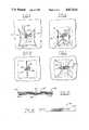
- FIGS. 5 through 8are fragmentary top views of the bag and the inlet spout of a liner illustrating how they are positioned and tied together and closed to prevent liquid from being syphoned out of the container;
- FIG. 9is a fragmentary sectional view of a modified container illustrating the connection of a discharge spout to a liquid outlet tube and valve assembly
- FIG. 10is a fragmentary sectional view taken generally on line 10--10 of FIG. 9 illustrating in greater detail the discharge spout and outlet tube and valve assembly;
- FIG. 11is a fragmentary view taken generally on the line 11--11 of FIG. 9 and illustrating trap doors covering access holes in the bottom of the cage;
- FIG. 12is a plan view of the bag in a flattened condition
- FIG. 13is a sectional view taken generally along the line 13--13 of FIG. 12;
- FIG. 14is a end view of the flattened bag taken generally in the direction of the arrows 14--14 of FIG. 12;
- FIG. 15is a sectional view of another container embodying this invention with a foldable shield and a bag filled with liquid received in a cage;
- FIG. 16is a fragmentary side view of the bag illustrating its discharge spout
- FIG. 17is a fragmentary sectional view of the discharge spout taken generally on line 17--17 of FIG. 16;
- FIG. 18is a perspective view of the foldable shield of the container of FIG. 15;
- FIG. 19is an enlarged and fragmentary sectional view taken generally on line 19--19 of FIG. 18 illustrating some of the details of the shield.
- FIG. 20is a perspective view of the container of FIG. 15 with the bag empty, the shield and bag folded and the walls of the cage released for folding;
- FIG. 21is a side view of the container of FIG. 15 with the cage walls partially collapsed.
- FIGS. 1-3illustrate a collapsible container 20 embodying this invention which has a collapsible bag 22 received in a cage 24.
- the bagis generally cubical and has a generally flat top 26, side walls 28, and bottom 30 with an outlet boot or spout 32 centrally located in the bottom.
- the baghas a closable inlet boot or spout 34 centrally located in the top, although for some applications the bag can be constructed so that essentially its entire top can be opened and closed.
- the cage 24is generally cubical, preferably open with no top, and has opposed pairs of side walls 36, 38 carried by a bottom 40 fixed to an underlying frame 42. To permit the insertion of tines of a lift truck under the frame for lifting and carrying the container, it is supported by legs 44 fixed to the frame. To permit the cages to be stacked one on top of the other, the legs have notches 46, which when stacked, engage and bear on the top edge of the side walls of an immediately underlying cage.
- the walls and the bottomare a mesh or an open grid of heavy wire or rods 48, 50 of steel extending transversely to each other and welded together at their points of intersection.
- shields in the form of separate sheets 52, 54are disposed between the bag and the walls and bottom of the cage.
- the sheetscan be attached to the walls and the bottom.
- the sheetsare of a lightweight plastic material, such as high density polyethylene plastic.
- each wall 36is hinged along one side edge to one of the walls 38 by a spiral rod 56.
- Each of the walls 54is similarly hinged adjacent a bottom edge to the bottom 40 of the cage by a spiral rod 58.
- These hingespermit each wall 36 to be folded back over the wall 38 to which it is hinged and then such wall 38 to be folded over the bottom so that when knocked down, all the walls are generally parallel to and stacked over the bottom.
- suitable collapsible containers with steel wire rods welded togetherare commercially available from Cargotainer Division of Adrian Frabricators, P.O. Box 518, Adrian, Mich. 49221. These cages are available with various exterior dimensions and load carrying capacities. For most applications, cages are satisfactory which have exterior dimensions of 44 inches in length by 44 inches in width by 40 inches in height and a load carrying capacity of 4,000 pounds. For some applications non-metallic cages may be desirable. Suitable non-metallic cages of structural foam molded polyethylene are commercially available from Xytec Plastics, Inc. of Lakewood-Tacoma, Industrial Park, P.O. Box 99057, Tacoma, Wash. 98499. These plastic cages have exterior dimensions of 44 inches in length by 44 inches in width by 40 inches in height and usually a load-carrying capacity of 2,000 to 2,500 pounds, and in some instances, up to 4,000 pounds.
- an access opening 70is provided in the bottom of the cage through which the spout 32 of the bag can be extended. As shown in FIG. 3 this spout can be retained in th cage by a trap door 72 receivable in the opening 70 and pivotally connected by loops 74 so that it can be swung downwardly out of the opening as shown in phantom at 76 in FIG. 3.
- the bags 78,80have generally the same configuration as and conform to the interior of the bag 22 in which they are inserted.
- each bag 78, 80also has a discharge spout and an inlet spout 84.
- these spoutsare longer than and can be extended beyond the corresponding spouts of the bag 22.
- woven polyethylene fabric and woven polypropylene fabrichave been highly satisfactory for making bags of great strength and polyethylene plastic film and polypropylene plastic film with a thickness in the range about 4 to 10 mil are highly satisfactory for making water impervious or leak-proof bags.
- a control valve assembly 86can be connected to the discharge spouts of the bags, as shown in FIG. 2.
- This assemblyhas an outer casing 88 with a hopper section 90 in which the discharge spouts 82 of the plastic film bags are received above a valve member 92 arranged for opening and closing an outlet passageway 94 defined by the casing.
- the valve assemblyis carried by and suspended under the outlet boot or spout 32 of the fabric bag 22 by four circumferentially spaced hooks 96, removably received in four equally circumferentially spaced grommets 98 in the boot. Where it is desired to use the valve assembly 86 with a container having only plastic film bags, the hooks 96 can be hung directly on the wire rods of the bottom of the cage.
- valve assembly 86The preferred construction and arrangement of the valve assembly 86 is illustrated and claimed in U.S. Pat. No. 4,518,106 issued on May 21, 1985, the disclosure of which is incorporated herein by reference, and hence the construction, arrangement and operation of this valve assembly will not be described in further detail herein.
- the cageWhen these spouts are being used to remove the contents of the bag, usually the cage is located at a convenient height above the floor to provide easy access to the spouts. If the contents are removed intermittently or over a substantial period of time, usually it is desirable to place the cage on a rack or other support which raises it above the floor so it is at a convenient level to manually grasp and manipulate the spouts or any valve connected thereto.
- Containers used to transport or move either liquid materials or many granular materials which flow easilyare normally subjected to frequent changes in the speed and/or direction of movement which cause the liquid or granular material to shift, move or slosh around in the bag, and thereby produce forces which frequently would be of sufficient magnitude to damage or destroy the bag and damage the cage of the container.
- movement of the liquid or granular materialcan be sufficiently retarded to prevent any damage to the bag and the cage by positively forcing the top of the bag into firm engagement with the material contained in the bag. As shown in FIG. 4, this can be accomplished by straps 100 overlying the top of the bag with their ends connected to the side walls of the cage at a height below the top of the bag when filled.
- the strapshave buckles 102 permitting the effective length of the straps to be adjusted.
- the strapsare drawn up or shortened sufficiently to bear on and urge the top of the bag into firm engagement with its contents.
- the strapsare drawn up sufficiently to force the underlying portions of the top of the bag into the liquid so that adjacent portions of the top bulge or billow up above the straps. While the theory by which this arrangement of the straps retards movement of the liquid sufficiently to avoid damage is unknown, in practice this arrangement has been found to be highly satisfactory.
- the inlet spout 84 of a liner plastic film bagbe adequately closed so that liquid will not initially leak out of it by wrapping a cord around the inlet spout, drawing it tight and tying it off.
- a capillary or syphoning actionis soon initiated which slowly removes liquid from the bag through the spout so that in a day or so, the container will be substantially emptied.
- the upper end of the spoutcan be retained above the top of its bag, and this syphoning or capillary action thereby avoided, by securing the filler spout to the inlet boot 34 of the fabric bag 22 and securing the sides of the boot together to support the spout, as shown FIGS. 5-8.
- a cord 104is tightly wrapped around the filler spout 84 of the plastic film bag, and tied off, preferably with a bow knot, so that it can be easily untied when desired.
- the tied off filler spoutis then secured to the boot of the fabric bag 22, preferably by tying the same cord 104 to the boot through one of the grommets 106. Securing the filler spout 84 to the boot 34 prevents the spout 84 from being drawn away and separated from this boot when the container is emptied through the discharge spout in the bottom of the film bag.
- the sides of the boot 34are then secured together with the filler spout 84 projecting outwardly between its sides, preferably by another cord 108 although it could be secured by the same cord 104 used to tie off the spout.
- the bight of the cord 108is secured to one wall of the boot through an eyelet 106 and then the runs of this cord are passed around the sides of the spout and thence through an eyelet 110 in a generally opposed wall of the boot as shown in FIG. 6.
- One runthen is passed through an eyelet 112 of another boot wall and the other run is passed through an eyelet 114 in a generally opposed boot wall, as shown in FIG. 7.
- the cord 108is then drawn up tight to pull the walls of the boot together with the spout 84 therebetween with its free end projecting outwardly beyond and generally about above the boot, and then tied off, as shown in FIG. 9, preferably with a bow knot so it can be readily untied when it is desired to open the boot and spout, such as when refilling the container.
- an outlet tube and valve assembly 120can be connected to the discharge spouts of the plastic film bags 78, 80.
- a rigid outlet tube 122 having a tapered portion 124 adjacent one endcan be inserted into the open end of the discharge spouts 125 and 126 of the film bags 78, 80.
- the spoutsare releasably sealed to the tube by an adjustable clamp 128, such as a hose clamp, which is preferably received in a recess 130 in the tube, to provide a liquid tight seal between the tube and the spouts.
- the clampis slipped over the spouts before the tube is inserted.
- the tubeis connected to the inlet side of a conventional shut off valve 132 and its outlet is connected to a discharge pipe 134.
- the outlet tube and valve assemblyis supported by an arm 136 which can be connected to a rack or other support on which the container is received so that the valve assembly is positioned at a convenient height above the floor so that it can be easily reached and manually manipulated.
- Loss of liquid from the container while the outlet tube 122 is being installed in the spouts 125, 126can be prevented by releasably clamping together the walls of the spouts top inch them off in an area 138 above that into which the outlet tube is to be inserted.
- To insure no liquid is lost during shipment and storage of a liquid filled containerit is often desirable to heat seal the lower end of the discharge spouts. If the spouts are heat sealed they can be releasably clamped or pinched off first, then cut off just above the heat seals, the outlet tube inserted in the now open end, the spouts clamped to the tube, and then the clamp released above the tube and removed. In this way the tube and valve assembly can be installed without losing any liquid.
- the spoutcan be releasably pinched off between two generally opposed flat members moved into firm engagement with the walls of the spouts.
- a bag 22is formed from a tube 150 of a woven fabric or a plastic material.
- a sheet of materialis formed into a tube by sewing or heat sealing the opposite side edges of the material together as at 152.
- the tubular blankhas a pair of flat overlying panels 154, 156 which are interconnected by inwardly folded gussets 158, 160. Since the bag as illustrated is generally square in cross section, each folded gusset 158 and 160 in width is approximately the same as the width of the flat panels 154 and 156. Thus, the fold lines 162 of the gussets extend lengthwise of the tube and lie closely adjacent the longitudinal center line thereof.
- the panels 154 and 156would be wider than the gussets 158 and 160, and the fold lines 162 of the gussets would be spaced from the longitudinal center line of the tube.
- the four corner portions of the tubeare stitched or heat sealed diagonally on opposite sides of the blank as at 164.
- These lines 164extend symmetrically from the opposite side edges of the tubular blank inwardly and toward the adjacent end of the blank and terminate at points 166 which are spaced apart on opposite sides of the longitudinal center line of the blank and which are also spaced inwardly from the opposite ends of the blank.
- additional lines of stitching or heat sealing 168extend from the points 166 lengthwise of the blank in parallel relation to the opposite ends of the blank.
- Panels 154 and 158 and the intermediate portions of gusset panels 158, 160are then slitted lengthwise from the opposite ends of the blank inwardly, as at 170 along lines that are parallel and spaced slightly laterally outwardly from the stitch or heat seal lines 168.
- the severing lines 170terminate at points 172 which are generally transversely aligned with the intersection points 166 between stitch or heat seal lines 168 and lines 164.
- the end portions of panels 154, 156 and gusset panels 158, 160are folded over several times and stitched or heat sealed together as at 176.
- the end portions of the flat panels 154, 156 and gusset panels 158, 160, which extend between the severing lines 170are also folded individually one or more times upon themselves and hemmed by stitching or heat sealing as at 178. Eyelets, cringles or similar fasteners 180 can be secured adjacent the edges, which are hemmed at 178, on the two flat panels 154, 156 and gusset panels 158, 160.
- the flat panels 154, 156 and gusset panels 158, 160which extend between the stitch or heat seal lines 168 form rectangularly shaped outlet and inlet spouts 32 and 34.
- FIGS. 15-21illustrate a modified container 180 which is particularly suitable for liquids.
- this containerhas a collapsible bag 182 received in a foldable shield 184, both of which are received in a collapsible cage 186.
- Cage 186is identical to cage 24 except that it does not have any access opening 70 and trap door 72 in the cage.
- both the bag 182 and the shield 184are constructed and arranged so that they can be folded up together in a generally flat and compact arrangement adjacent a side wall of the cage as shown in FIG. 20.
- the bag 182is constructed in accordance with U.S. Pat. No. 4,596,040 which will readily fold into this generally flat configuration.
- the bag 182has an inlet spout 188 and an outlet spout 190 (FIGS. 16 and 17) in a side wall of the bag and immediately adjacent the bottom.
- the bagis made with two sheets of plastic film 192 and 194, one disposed within the other, and each heat sealed at 196 and 198 to a flange 200 of the outlet spout.
- Each heat seal 198 and 200is circumferentially continuous and encircles the neck of the spout.
- this spoutis both closed and protected by a closure cap 202 received on threads 204 on the neck of the spout.
- a portion 206 of the inner sheet of plastic film 194extends over and covers the inner end of the spout.
- the portion 206 of the inner filmis pierced by inserting a sharp instrument through the spout.
- the spout 190projects through the foldable shield 184 and an opening in a side wall of the cage between the wire rods, as shown in FIG. 20.
- the bag 182can be made with a spout 190 in its bottom, rather than its side, for which it is desirable, but usually unnecessary, to provide an access opening and a trap door in the bottom of the cage.
- the foldable shield 184preferably has a pair of generally flat side panels 208 and 210 interconnected by gusset panels 212 and 214. All of the panels are preferably self-supporting and hingedly connected together at their adjacent vertical edges. Preferably, the panels are made from a tube of self-supporting plastic material by forming fold lines therein corresponding to the adjacent vertical edges to provide integral and continuously hinged joints which prevent the plastic film bags from being pinched or snagged when the shield is folded up. The tube is formed by heat sealing together the opposite ends of a sheet of plastic material. A sheet of high density polyethylene or polypropylene plastic with a thickness of 20 to 30 mils is highly satisfactory.
- the shieldhas a top cover 216 and a bottom 218 of a flexible woven fabric material.
- one edge of the top 216is attached to the panel 208 adjacent its upper end by stitching 220.
- the bottomis attached to the lower edge of each panel by stitching 222 along a continuous line around the periphery of the shield.
- the shield 184is attached to one side wall 38 by cords 224 passing through slots 226 and 228 in the panel 208 and tied to a wire rod of the cage.
- an access hole 230through the top of the bag.
- a clearance hole 232is provided in the panel 208 of the shield.
- the shield 184can be folded into a generally flat and compact configuration with the gusset panels 212 and 214 received between the wall panels 208 and 210.
- the bagwill also be simultaneously collapsed with and inside of the shield.
- Each cage wall 36is released and pivoted (FIG. 20) through 180° to overlie its associated wall 38.
- FIGS. 21one wall 38 and then the other is pivotally moved through an arc of 90° to overlie the bottom of the cage, which results in the container being collapsed into a compact package for storage and shipment prior to being set up for reuse.
- the side walls of the cage of the containerare collapsed to conserve space and provide a compact package.
- the empty bag or bags therein and any foldable shieldare collapsed within the cage before the walls of the cage are folded over its bottom.
- the bagscan still be folded with their flat panels and gussets disposed generally as shown in FIGS. 12-14 to provide a compact separate package facilitating storage and shipment.
- the shield and the bag or bagscan be inserted in the cage if they are not already received therein.
- the discharge spout or spouts of any plastic film bag or bagsare tied off or preferably heat sealed and then folded into any woven fabric outer bag through its outlet boot.
- the walls of the outlet bootare then folded up and tied or otherwise secured together through the eyelets therein.
- Any trap doors in the bottom of the cageare closed to support the bags when filled. If no trap doors are provided a bolt, straps, cord or other means can be extended across any access opening, drawn taught and secured to the bottom of the cage to provide support for the bags when filled.
- the containeris then filled with a liquid or granular material through the inlet spout.
- the inlet spout of any plastic film bagis closed off, such as by tying or preferably heat sealing and then the inlet spout or boot of any fabric outer bag is closed and tied off.
- the spoutshould be secured to the outer woven bag and tied up between the walls of the upper boot of the woven bag so that the spout extends generally outwardly with its free ends projecting out of the boot as discussed above and shown in FIGS. 5-8, to prevent a syphoning or capillary action from subsequently draining the liquid from the container.
- the straps 100are placed over the top of the outer fabric bag or the fabric top of the foldable shield and drawn up sufficiently to force the top of the bag or bags into firm engagement with the contents. If the material is a liquid, preferably the straps are shortened sufficiently to force out any air initially entrapped in the plastic film bag so that the liquid begins to rise in the filler spout. If the filler spout is to be heat sealed, it may be necessary to shorten or tension the straps before the filler spout is heat sealed and thereafter fold the sealed spout into any outer fabric bag.
- the filled containercan then be stored, transported and moved about until it is desired to remove its contents. If the bag has an outlet spout in its side the cap is removed and any plastic film underlying the spout pierced so that the liquid contents can flow out through the spout.
- the baghas a bottom spout, preferably its contents is removed through the bottom of the container while the bag is still in the cage.
- the containeris lifted above the floor to provide access to the bottom and then any trap doors are opened to provide access to the outlet boot or spout of any outer bag and the spout of any plastic film bags therein.
- the cordis untied, or other securing means released, to open the outlet boot of the outer bag and, if there is no plastic film inner bag, the material is discharged through this boot. If there is a plastic film inner bag, its spout is pulled through any outer bag outlet or boot and then opened to discharge the contents.
- a suitable valve assemblysuch as the discharge valve assembly 86, can be installed to do so. If it is desired to. intermittently discharge liquid from the container, a suitable outlet tube and valve assembly, such as the assembly 120, can be installed and connected to the discharge spout to do so.
- any discharge valve assemblyis disconnected and removed. Thereafter, the bag or bags preferably are collapsed within the cage or removed and folded into a compact arrangement for storage and shipment before reuse. With the bag or bags either therein or removed, but preferably therein, any foldable shield is folded and then the sidewalls of the cage are released, collapsed and folded over the bottom of the cage to provide a compact package for storage and shipment before reuse.
- the walls of the cageare reassembled in the upright position, any foldable shield unfolded, and the bag or bags therein prepared for refilling in the manner already described so the container can be reused to store and ship granular or liquid materials.
Landscapes
- Engineering & Computer Science (AREA)
- Mechanical Engineering (AREA)
- Bag Frames (AREA)
Abstract
Description
Claims (39)
Priority Applications (1)
| Application Number | Priority Date | Filing Date | Title |
|---|---|---|---|
| US06/939,421US4817824A (en) | 1986-12-08 | 1986-12-08 | Collapsible bulk container |
Applications Claiming Priority (1)
| Application Number | Priority Date | Filing Date | Title |
|---|---|---|---|
| US06/939,421US4817824A (en) | 1986-12-08 | 1986-12-08 | Collapsible bulk container |
Publications (1)
| Publication Number | Publication Date |
|---|---|
| US4817824Atrue US4817824A (en) | 1989-04-04 |
Family
ID=25473158
Family Applications (1)
| Application Number | Title | Priority Date | Filing Date |
|---|---|---|---|
| US06/939,421Expired - LifetimeUS4817824A (en) | 1986-12-08 | 1986-12-08 | Collapsible bulk container |
Country Status (1)
| Country | Link |
|---|---|
| US (1) | US4817824A (en) |
Cited By (100)
| Publication number | Priority date | Publication date | Assignee | Title |
|---|---|---|---|---|
| US4863065A (en)* | 1988-09-26 | 1989-09-05 | Decrane Charles E | Bulk bag discharge unit and method |
| US4953729A (en)* | 1989-04-12 | 1990-09-04 | George Kloosterhouse | Sanitation shield for water cooler bottle |
| WO1991010608A1 (en)* | 1990-01-18 | 1991-07-25 | Koninklijke Emballage Industrie Van Leer B.V. | Collapsible container |
| US5050765A (en)* | 1988-10-15 | 1991-09-24 | Sotralentz S.A. | Transport and/or storage container for flowable materials |
| US5056667A (en)* | 1988-05-17 | 1991-10-15 | Rees Operations Pty. Ltd. | Collapsible pallet cage |
| DE4237889A1 (en)* | 1991-11-14 | 1993-06-03 | Schuetz Werke Gmbh Co Kg | |
| US5244280A (en)* | 1992-05-27 | 1993-09-14 | Megasack Corporation | Flexible intermediate bulk containers |
| US5257893A (en)* | 1992-03-10 | 1993-11-02 | Sevits Terry L | Portable dispenser apparatus for bulk bags |
| US5287985A (en)* | 1991-04-17 | 1994-02-22 | Morishita Chemical Industry, Co., Ltd. | Container for dewatering or packaging and transportation |
| US5297401A (en)* | 1993-04-19 | 1994-03-29 | Hawco James H | Ice maker reservoir apparatus |
| US5318219A (en)* | 1992-06-05 | 1994-06-07 | Four M Manufacturing Group Of Cpc, Inc. | Collapsible pallet mounted container |
| US5340218A (en)* | 1993-03-19 | 1994-08-23 | Transac, Inc. | Bulk storage bag with remotely openable discharge spout |
| US5385268A (en)* | 1993-05-25 | 1995-01-31 | Custom Packaging Systems, Inc. | Liner outlet seal and tool |
| US5507392A (en)* | 1993-07-28 | 1996-04-16 | Schutz-Werke Gmbh & Co. Kg | Pallet container with adapter frame |
| US5531360A (en)* | 1993-08-02 | 1996-07-02 | Cerdec Aktiengesellschaft Keramische Farben | Metering pallet |
| US5542541A (en)* | 1994-08-31 | 1996-08-06 | Four M Manufacturing Group Of Cpc, Inc. | Multi-sided collapsible container |
| US5566851A (en)* | 1990-04-11 | 1996-10-22 | Dai Nippon Insatsu Kabushiki Kaisha | Liquid container and mouth thereof |
| AT401917B (en)* | 1993-11-19 | 1996-12-27 | Lisec Peter | Container for free-flowing materials |
| US5618254A (en)* | 1995-04-27 | 1997-04-08 | Super Sack Mfg. Corp. | Gusseted bulk bag liner and method of manufacture |
| US5649643A (en)* | 1994-07-18 | 1997-07-22 | Daniel Barnabas Harasty | Flexible container having a retractable dispenser |
| US5653354A (en)* | 1995-08-21 | 1997-08-05 | Noslo Enterprises, Inc. | Stackable container system for flowable materials |
| WO1997037897A1 (en)* | 1996-04-10 | 1997-10-16 | Seec, Inc. | Reusable flexible transport container |
| US5690253A (en)* | 1996-08-29 | 1997-11-25 | Custom Packaging Systems, Inc. | Large bulk liquid squeeze bag |
| US5701650A (en)* | 1993-05-25 | 1997-12-30 | Custom Packaging Systems, Inc. | Tools for inserting and removing liner outlet spouts |
| US5722552A (en)* | 1995-08-21 | 1998-03-03 | Noslo Enterprises, Inc. | Collapsible stackable container system for flowable materials |
| US5851072A (en)* | 1996-11-26 | 1998-12-22 | Custom Packaging Systems, Inc. | Spout construction for bulk box liquid liner |
| US5897012A (en)* | 1997-04-04 | 1999-04-27 | Sortwell & Co. | Collapsible intermediate bulk container |
| US5947333A (en)* | 1998-02-25 | 1999-09-07 | Hoffman | Bulk bag discharge system and method |
| US5947312A (en)* | 1997-12-02 | 1999-09-07 | Elstone; Paul | Reusable container system |
| US6305845B1 (en)* | 2000-02-07 | 2001-10-23 | Grayling Industries, Inc. | Lined bulk bag |
| US6352178B1 (en)* | 1999-04-22 | 2002-03-05 | Wakayama Seika Kogyo Co., Ltd. | Flexible container |
| GB2366789A (en)* | 2000-09-06 | 2002-03-20 | Tickhill Eng Co Ltd | A Storage Receptacle Comprising a Frame and Liner |
| US6454113B1 (en)* | 1999-11-27 | 2002-09-24 | Protechna S.A. | Transport and storage container for liquids and method for manufacturing the inner container of the transport and storage container |
| US6478176B1 (en)* | 1996-12-13 | 2002-11-12 | William P. Reiter | Molded container assembly for transporting bulk material |
| US20030029982A1 (en)* | 2001-03-19 | 2003-02-13 | Hurst William S. | Container support |
| US6616103B2 (en)* | 2000-11-17 | 2003-09-09 | Louis Marrero | Cargo container apparatus, cargo container and methods of loading cargo |
| WO2003084831A1 (en)* | 2002-04-01 | 2003-10-16 | Ilc Dover, Inc. | Flexible containment charging device |
| US20030198406A1 (en)* | 2002-04-12 | 2003-10-23 | Hynetics Llc | Feed bags and methods of use |
| AT411172B (en)* | 2001-10-10 | 2003-10-27 | Heinz Wittmann | Container for transporting drinks under pressure, e.g. beer or lemonade, comprises cylindrical keg with lid containing disposable bag which can be filled through inlet in lid |
| US6659132B2 (en) | 2001-03-19 | 2003-12-09 | Baxter International Inc. | Gas permeable sterile closure |
| US20040016215A1 (en)* | 2000-11-15 | 2004-01-29 | Hoogland Hendrik Antonius | Method and device for packaging cocoa beans and such natural products |
| US20040074922A1 (en)* | 2001-01-08 | 2004-04-22 | Bothor Kerim Patrick | Device for large-volume containers |
| US20040118725A1 (en)* | 2002-12-19 | 2004-06-24 | Shuert Lyle H. | Bulk container with plastic liner |
| WO2004080846A1 (en)* | 2003-03-11 | 2004-09-23 | Oy Web-Cat Ltd | Transportation container |
| WO2004096661A1 (en)* | 2003-05-02 | 2004-11-11 | Almar Packaging International Inc | Intermediate bulk container |
| US20040261725A1 (en)* | 2003-06-19 | 2004-12-30 | Hyper Products, Inc. | Storage containers and method of storing products used by animals |
| US6902061B1 (en)* | 2000-09-29 | 2005-06-07 | Paul Elstone | Collapsible liquid box |
| US20050284080A1 (en)* | 2004-06-29 | 2005-12-29 | Gallego Jorge E | Bastions for force protection and military applications |
| US7073676B1 (en)* | 2001-08-15 | 2006-07-11 | Pactec, Inc. | Containment bag system for use in a commercial disposal container |
| US20060165320A1 (en)* | 2003-01-02 | 2006-07-27 | Stephens Thomas C | Inlet port for a container made of geotextiles |
| US20070093776A1 (en)* | 2005-10-25 | 2007-04-26 | Stephens Thomas C | Methods, systems, and apparatus for a fill port for a flexible container |
| US20070127852A1 (en)* | 2005-02-28 | 2007-06-07 | Troy Town | Lifting Bag |
| US20070140598A1 (en)* | 2005-12-15 | 2007-06-21 | Mcgillick Jon Sr | Shoreline erosion and flood control system and method |
| US20070227938A1 (en)* | 2006-03-31 | 2007-10-04 | Custom Metalcraft, Inc. | Foldable container |
| US20070227937A1 (en)* | 2006-03-31 | 2007-10-04 | Custom Metalcraft, Inc. | Foldable container |
| US20080017649A1 (en)* | 2003-03-28 | 2008-01-24 | Hyclone Laboratories, Inc. | Fluid dispensing bins |
| US20080031550A1 (en)* | 2005-02-28 | 2008-02-07 | Troy Town | Lifting Bag Device |
| US7384783B2 (en) | 2004-04-27 | 2008-06-10 | Baxter International Inc. | Stirred-tank reactor system |
| US20080137997A1 (en)* | 2006-12-12 | 2008-06-12 | Plastic Systems, Inc. | Bulk container |
| US20090001089A1 (en)* | 2007-06-28 | 2009-01-01 | Britt Mark W | Portable and/or collapsible containers having pliable surfaces |
| US20090151293A1 (en)* | 2004-06-29 | 2009-06-18 | Ryan Christman | Bastions for Force Protection and Military Applications |
| US20090277900A1 (en)* | 2008-05-08 | 2009-11-12 | Stephen Charles Howison | Container for storage and transport of liquids |
| US20090314715A1 (en)* | 2007-10-04 | 2009-12-24 | Conwell Michael K | Method of dewatering solids laden liquids utilizing a reusable filter element |
| US20100065710A1 (en)* | 2008-04-17 | 2010-03-18 | James Austin | Apparatus to retain and position tubing of media bags |
| FR2936230A1 (en)* | 2008-09-25 | 2010-03-26 | Jean Luc Sauzaret | Storage device i.e. transformable and foldable metallic meshed basket, for e.g. heavy load industrial refuses and materials, has base sized for supporting load of specific tons, by capturing load in structure using round lifting lugs |
| US7845511B1 (en) | 2001-08-15 | 2010-12-07 | Pactec, Inc. | Containment bag for use in a commercial disposal container |
| US20100322538A1 (en)* | 2009-06-22 | 2010-12-23 | Powell Greg L | Flexible bulk containers constructed to be liftable from below by a forklift |
| US20110131932A1 (en)* | 2005-02-18 | 2011-06-09 | Ours David C | Bulk transport system for dense products |
| US20110168593A1 (en)* | 2010-01-08 | 2011-07-14 | Woodhaven Capitol Corp. | Folding seed box with fork lift base |
| US20110168702A1 (en)* | 2010-01-08 | 2011-07-14 | Woodhaven Capitol Corp. | Folding seed box |
| US20110290752A1 (en)* | 2010-05-27 | 2011-12-01 | Yeager Don F | Inverted bottle assembly |
| US20120018427A1 (en)* | 2010-07-22 | 2012-01-26 | Slingfin, Inc. | Collapsible Durable Outdoor Adventure Container |
| US20120111862A1 (en)* | 2007-08-06 | 2012-05-10 | Peter Trepte | Container Side Wall, Container with such a Container Side Wall, and Product-Transporting Receptacle with such a Container |
| US8191722B1 (en)* | 2001-08-15 | 2012-06-05 | Pactec, Inc. | Containment bag system for use in a commercial disposal container |
| US20120198792A1 (en)* | 2004-10-01 | 2012-08-09 | Long Life S.R.L. | Process for good packaging, namely food stuffs, packagings and kits for their realization |
| US20120281932A1 (en)* | 2009-12-02 | 2012-11-08 | Imerys Talc America, Inc. | Flexible bulk storage container having a discharge chute |
| US8562212B1 (en) | 2006-06-23 | 2013-10-22 | Pactec, Inc. | Containment bag for use in a commercial disposal container |
| NL2008945C2 (en)* | 2012-06-06 | 2013-12-09 | Paul Robert Wolschrijn | INDUSTRIAL PROCESS TANK, AND METHOD FOR ESTABLISHING THEM. |
| US20130330023A1 (en)* | 2012-06-07 | 2013-12-12 | John McGeoghean | Reusable, Multi-Purpose Dumpster Bag |
| US20140029872A1 (en)* | 2012-06-22 | 2014-01-30 | Danny Ness | Bulk bag apparatus |
| US20140154045A1 (en)* | 2012-12-03 | 2014-06-05 | Chi Mei Corporation | Flexible freight bag and method of transferring cargo using the same |
| US8777060B2 (en)* | 2012-01-16 | 2014-07-15 | Spiroflow Systems, Inc. | Discharger for side-secured bag spout |
| US8777001B1 (en) | 2009-07-07 | 2014-07-15 | William Duffy Bennett | Oil containment bag / container for the transporting and storage of electrical transformers of all types (I.E. all pole, pad mount and underground models etc.) |
| US20150023733A1 (en)* | 2012-02-01 | 2015-01-22 | Daniel R. Schnaars, SR. | Reusable and removable flexible bag or cell flood wall protection system |
| US20150128536A1 (en)* | 2012-01-19 | 2015-05-14 | Xinyu Liu | Cooking material dispensing method and dispensing system |
| US9149743B2 (en) | 2007-10-04 | 2015-10-06 | Michael K. Conwell | Apparatus for dewatering solids-laden liquids |
| US20170174425A1 (en)* | 2015-07-10 | 2017-06-22 | Beijing Sihai Futong Energy Technology Co.,Ltd. | Foldaway bracket flexible liquid storage tank |
| US9908694B2 (en) | 2015-03-01 | 2018-03-06 | Waste Container Systems L.L.C. | Lightweight commercial dumpster |
| WO2018029079A3 (en)* | 2016-08-09 | 2018-04-05 | Lodestone Engineering Limited | A compactor and a method of operation of a compactor |
| IT201700015045A1 (en)* | 2017-02-10 | 2018-08-10 | Gbs Trading Company Di Beldrighi Graziano | FOLDING CONTAINER FOR TRANSPORT OF REBUFFERED MATERIAL |
| US10173813B2 (en) | 2016-09-29 | 2019-01-08 | Dow Global Technologies Llc | Flexible container with pop-up spout |
| US10273070B2 (en) | 2017-05-19 | 2019-04-30 | Paper Systems, Inc. | Collapsible container |
| US10759584B2 (en) | 2018-03-02 | 2020-09-01 | Life Technologies Corporation | System for port and tube holder assembly attachment device and methods of use |
| US11192764B2 (en)* | 2017-04-24 | 2021-12-07 | MCF Distributing, LLC | Pan assembly for aerial work platform |
| US11407583B2 (en)* | 2018-11-30 | 2022-08-09 | Schoeller Allibert Gmbh | Intermediate bulk container |
| US20220267084A1 (en)* | 2021-02-25 | 2022-08-25 | Freedom Manufacturing LLC | Liner structure with constrictable sidewall and method to install same |
| US11840684B2 (en) | 2011-09-29 | 2023-12-12 | Life Technologies Corporation | Filter systems for separating microcarriers from cell culture solutions |
| US20240270480A1 (en)* | 2023-02-14 | 2024-08-15 | Hecht Technologie Gmbh | Container, in particular package |
| US12336526B2 (en)* | 2013-11-18 | 2025-06-24 | 0903608 B.C. Ltd. | Compositions, devices and methods for plant health and pest control using vapor activity |
| US12342808B2 (en)* | 2013-11-18 | 2025-07-01 | 0903608 B.C. Ltd. | Compositions, devices and methods for control of pests using vapor activity |
Citations (15)
| Publication number | Priority date | Publication date | Assignee | Title |
|---|---|---|---|---|
| US824566A (en)* | 1905-11-20 | 1906-06-26 | James F Moss | Shipping-crate. |
| US2432025A (en)* | 1944-03-03 | 1947-12-02 | Henry W Lorenz | Collapsible gasoline tank |
| US2720998A (en)* | 1951-12-06 | 1955-10-18 | Clifford S Potter | Collapsible container |
| US2735568A (en)* | 1956-02-21 | bitney | ||
| US2973119A (en)* | 1957-04-15 | 1961-02-28 | Parker Brooks O'c | Portable container for liquids |
| US3295738A (en)* | 1965-03-23 | 1967-01-03 | West Virginia Pulp & Paper Co | Semi-bulk shipping bag |
| US3908864A (en)* | 1970-09-28 | 1975-09-30 | Max V Capper | Container for bulk liquids such as milk |
| US4306669A (en)* | 1979-09-19 | 1981-12-22 | Grether Tobias H A | Livestock ration transport and storage |
| US4314768A (en)* | 1978-05-05 | 1982-02-09 | Luigi Goglio | Syrup feed system for drink distribution apparatus of the after-mixing type |
| US4390051A (en)* | 1981-04-03 | 1983-06-28 | Bonar Industries Inc. | Securing a liner within a flexible container |
| US4421253A (en)* | 1982-02-17 | 1983-12-20 | Willamette Industries, Inc. | Disposable container assembly for liquids or semi-liquids in bulk |
| US4518106A (en)* | 1984-05-21 | 1985-05-21 | Custom Packaging Systems, Inc. | Collapsible bag and discharge valve therefor |
| US4585143A (en)* | 1984-01-25 | 1986-04-29 | Boise Cascade Corporation | Liquid container |
| US4596040A (en)* | 1982-09-30 | 1986-06-17 | Custom Packaging Systems | Large bulk bag |
| US4691371A (en)* | 1985-12-26 | 1987-09-01 | Super Sack Manufacturing Corporation | Receptacle having improved discharge spout |
- 1986
- 1986-12-08USUS06/939,421patent/US4817824A/ennot_activeExpired - Lifetime
Patent Citations (15)
| Publication number | Priority date | Publication date | Assignee | Title |
|---|---|---|---|---|
| US2735568A (en)* | 1956-02-21 | bitney | ||
| US824566A (en)* | 1905-11-20 | 1906-06-26 | James F Moss | Shipping-crate. |
| US2432025A (en)* | 1944-03-03 | 1947-12-02 | Henry W Lorenz | Collapsible gasoline tank |
| US2720998A (en)* | 1951-12-06 | 1955-10-18 | Clifford S Potter | Collapsible container |
| US2973119A (en)* | 1957-04-15 | 1961-02-28 | Parker Brooks O'c | Portable container for liquids |
| US3295738A (en)* | 1965-03-23 | 1967-01-03 | West Virginia Pulp & Paper Co | Semi-bulk shipping bag |
| US3908864A (en)* | 1970-09-28 | 1975-09-30 | Max V Capper | Container for bulk liquids such as milk |
| US4314768A (en)* | 1978-05-05 | 1982-02-09 | Luigi Goglio | Syrup feed system for drink distribution apparatus of the after-mixing type |
| US4306669A (en)* | 1979-09-19 | 1981-12-22 | Grether Tobias H A | Livestock ration transport and storage |
| US4390051A (en)* | 1981-04-03 | 1983-06-28 | Bonar Industries Inc. | Securing a liner within a flexible container |
| US4421253A (en)* | 1982-02-17 | 1983-12-20 | Willamette Industries, Inc. | Disposable container assembly for liquids or semi-liquids in bulk |
| US4596040A (en)* | 1982-09-30 | 1986-06-17 | Custom Packaging Systems | Large bulk bag |
| US4585143A (en)* | 1984-01-25 | 1986-04-29 | Boise Cascade Corporation | Liquid container |
| US4518106A (en)* | 1984-05-21 | 1985-05-21 | Custom Packaging Systems, Inc. | Collapsible bag and discharge valve therefor |
| US4691371A (en)* | 1985-12-26 | 1987-09-01 | Super Sack Manufacturing Corporation | Receptacle having improved discharge spout |
Cited By (152)
| Publication number | Priority date | Publication date | Assignee | Title |
|---|---|---|---|---|
| US5056667A (en)* | 1988-05-17 | 1991-10-15 | Rees Operations Pty. Ltd. | Collapsible pallet cage |
| US4863065A (en)* | 1988-09-26 | 1989-09-05 | Decrane Charles E | Bulk bag discharge unit and method |
| US5050765A (en)* | 1988-10-15 | 1991-09-24 | Sotralentz S.A. | Transport and/or storage container for flowable materials |
| US4953729A (en)* | 1989-04-12 | 1990-09-04 | George Kloosterhouse | Sanitation shield for water cooler bottle |
| WO1991010608A1 (en)* | 1990-01-18 | 1991-07-25 | Koninklijke Emballage Industrie Van Leer B.V. | Collapsible container |
| US5566851A (en)* | 1990-04-11 | 1996-10-22 | Dai Nippon Insatsu Kabushiki Kaisha | Liquid container and mouth thereof |
| US5287985A (en)* | 1991-04-17 | 1994-02-22 | Morishita Chemical Industry, Co., Ltd. | Container for dewatering or packaging and transportation |
| US5366090A (en)* | 1991-11-14 | 1994-11-22 | Schuetz Udo | Pallet container |
| DE4237889A1 (en)* | 1991-11-14 | 1993-06-03 | Schuetz Werke Gmbh Co Kg | |
| US5257893A (en)* | 1992-03-10 | 1993-11-02 | Sevits Terry L | Portable dispenser apparatus for bulk bags |
| US5244280A (en)* | 1992-05-27 | 1993-09-14 | Megasack Corporation | Flexible intermediate bulk containers |
| US5318219A (en)* | 1992-06-05 | 1994-06-07 | Four M Manufacturing Group Of Cpc, Inc. | Collapsible pallet mounted container |
| US5340218A (en)* | 1993-03-19 | 1994-08-23 | Transac, Inc. | Bulk storage bag with remotely openable discharge spout |
| US5297401A (en)* | 1993-04-19 | 1994-03-29 | Hawco James H | Ice maker reservoir apparatus |
| US5385268A (en)* | 1993-05-25 | 1995-01-31 | Custom Packaging Systems, Inc. | Liner outlet seal and tool |
| US5701650A (en)* | 1993-05-25 | 1997-12-30 | Custom Packaging Systems, Inc. | Tools for inserting and removing liner outlet spouts |
| US5507392A (en)* | 1993-07-28 | 1996-04-16 | Schutz-Werke Gmbh & Co. Kg | Pallet container with adapter frame |
| US5531360A (en)* | 1993-08-02 | 1996-07-02 | Cerdec Aktiengesellschaft Keramische Farben | Metering pallet |
| AT401917B (en)* | 1993-11-19 | 1996-12-27 | Lisec Peter | Container for free-flowing materials |
| US5649643A (en)* | 1994-07-18 | 1997-07-22 | Daniel Barnabas Harasty | Flexible container having a retractable dispenser |
| US5542541A (en)* | 1994-08-31 | 1996-08-06 | Four M Manufacturing Group Of Cpc, Inc. | Multi-sided collapsible container |
| US5618254A (en)* | 1995-04-27 | 1997-04-08 | Super Sack Mfg. Corp. | Gusseted bulk bag liner and method of manufacture |
| US5984850A (en)* | 1995-04-27 | 1999-11-16 | Super Sack Mfg. Corp. | Gusseted bulk bag liner and method of manufacture |
| US5653354A (en)* | 1995-08-21 | 1997-08-05 | Noslo Enterprises, Inc. | Stackable container system for flowable materials |
| US5722552A (en)* | 1995-08-21 | 1998-03-03 | Noslo Enterprises, Inc. | Collapsible stackable container system for flowable materials |
| WO1997037897A1 (en)* | 1996-04-10 | 1997-10-16 | Seec, Inc. | Reusable flexible transport container |
| US5690253A (en)* | 1996-08-29 | 1997-11-25 | Custom Packaging Systems, Inc. | Large bulk liquid squeeze bag |
| US5851072A (en)* | 1996-11-26 | 1998-12-22 | Custom Packaging Systems, Inc. | Spout construction for bulk box liquid liner |
| US6090029A (en)* | 1996-11-26 | 2000-07-18 | Custom Packaging Systems, Inc. | Spout construction for bulk box liquid liner |
| US6478176B1 (en)* | 1996-12-13 | 2002-11-12 | William P. Reiter | Molded container assembly for transporting bulk material |
| US5897012A (en)* | 1997-04-04 | 1999-04-27 | Sortwell & Co. | Collapsible intermediate bulk container |
| US5947312A (en)* | 1997-12-02 | 1999-09-07 | Elstone; Paul | Reusable container system |
| US5947333A (en)* | 1998-02-25 | 1999-09-07 | Hoffman | Bulk bag discharge system and method |
| US6076702A (en)* | 1998-02-25 | 2000-06-20 | Spiroflow-Orthos Systems, Inc. | Bulk bag discharge system and method |
| US6352178B1 (en)* | 1999-04-22 | 2002-03-05 | Wakayama Seika Kogyo Co., Ltd. | Flexible container |
| US6454113B1 (en)* | 1999-11-27 | 2002-09-24 | Protechna S.A. | Transport and storage container for liquids and method for manufacturing the inner container of the transport and storage container |
| AU767065B2 (en)* | 1999-11-27 | 2003-10-30 | Protechna S.A. | Transport and storage container for liquids and method to manufacture the inner container of the transport and storage container |
| US6305845B1 (en)* | 2000-02-07 | 2001-10-23 | Grayling Industries, Inc. | Lined bulk bag |
| GB2366789A (en)* | 2000-09-06 | 2002-03-20 | Tickhill Eng Co Ltd | A Storage Receptacle Comprising a Frame and Liner |
| GB2366789B (en)* | 2000-09-06 | 2004-09-01 | Tickhill Eng Co Ltd | Storage receptacle |
| US6902061B1 (en)* | 2000-09-29 | 2005-06-07 | Paul Elstone | Collapsible liquid box |
| US20040016215A1 (en)* | 2000-11-15 | 2004-01-29 | Hoogland Hendrik Antonius | Method and device for packaging cocoa beans and such natural products |
| US7069706B2 (en)* | 2000-11-15 | 2006-07-04 | =Innospecial Products B.V. | Device for packaging cocoa beans and such natural products |
| US6616103B2 (en)* | 2000-11-17 | 2003-09-09 | Louis Marrero | Cargo container apparatus, cargo container and methods of loading cargo |
| AU2002224975B2 (en)* | 2001-01-08 | 2007-11-01 | Kerim Patrick Bothor | Device for large-volume containers |
| US7140516B2 (en)* | 2001-01-08 | 2006-11-28 | Kerim Patrick Bothor | Device for large-volume containers |
| US20040074922A1 (en)* | 2001-01-08 | 2004-04-22 | Bothor Kerim Patrick | Device for large-volume containers |
| US20030029982A1 (en)* | 2001-03-19 | 2003-02-13 | Hurst William S. | Container support |
| US6659132B2 (en) | 2001-03-19 | 2003-12-09 | Baxter International Inc. | Gas permeable sterile closure |
| US7025318B2 (en)* | 2001-03-19 | 2006-04-11 | Baxter International Inc. | Container support |
| US20030075663A1 (en)* | 2001-03-19 | 2003-04-24 | Hurst William S. | Container support |
| US20030075662A1 (en)* | 2001-03-19 | 2003-04-24 | Hurst William S. | Container support |
| US7188744B2 (en) | 2001-03-19 | 2007-03-13 | Baxter International Inc. | Container support |
| US8777034B1 (en) | 2001-08-15 | 2014-07-15 | Pactec, Inc. | Containment bag system for use in a commercial disposal container |
| US8499953B1 (en) | 2001-08-15 | 2013-08-06 | Pactec, Inc. | Containment bag for use in a commercial disposal container |
| US8191722B1 (en)* | 2001-08-15 | 2012-06-05 | Pactec, Inc. | Containment bag system for use in a commercial disposal container |
| US7845511B1 (en) | 2001-08-15 | 2010-12-07 | Pactec, Inc. | Containment bag for use in a commercial disposal container |
| US7073676B1 (en)* | 2001-08-15 | 2006-07-11 | Pactec, Inc. | Containment bag system for use in a commercial disposal container |
| AT411172B (en)* | 2001-10-10 | 2003-10-27 | Heinz Wittmann | Container for transporting drinks under pressure, e.g. beer or lemonade, comprises cylindrical keg with lid containing disposable bag which can be filled through inlet in lid |
| US20050081950A1 (en)* | 2002-04-01 | 2005-04-21 | Ilc Dover, Inc | Flexible containment charging device |
| WO2003084831A1 (en)* | 2002-04-01 | 2003-10-16 | Ilc Dover, Inc. | Flexible containment charging device |
| US20030198406A1 (en)* | 2002-04-12 | 2003-10-23 | Hynetics Llc | Feed bags and methods of use |
| US7168459B2 (en) | 2002-04-12 | 2007-01-30 | Hynetics Llc | Feed bags and methods of use |
| US6968946B2 (en)* | 2002-12-19 | 2005-11-29 | Shuert Lyle H | Bulk container with plastic liner |
| US20040118725A1 (en)* | 2002-12-19 | 2004-06-24 | Shuert Lyle H. | Bulk container with plastic liner |
| US20060165320A1 (en)* | 2003-01-02 | 2006-07-27 | Stephens Thomas C | Inlet port for a container made of geotextiles |
| WO2004080846A1 (en)* | 2003-03-11 | 2004-09-23 | Oy Web-Cat Ltd | Transportation container |
| RU2320524C2 (en)* | 2003-03-11 | 2008-03-27 | Ой Веб-Кат Лтд. | Shipment container |
| US20060261059A1 (en)* | 2003-03-11 | 2006-11-23 | Anita Jokinen | Transportation container |
| US20080017649A1 (en)* | 2003-03-28 | 2008-01-24 | Hyclone Laboratories, Inc. | Fluid dispensing bins |
| US7992598B2 (en) | 2003-03-28 | 2011-08-09 | Hyclone Laboratories, Inc. | Fluid bin assembly with hoist |
| US8272410B2 (en) | 2003-03-28 | 2012-09-25 | Hyclone Laboratories, Inc. | Fluid bin assembly with hoist |
| US7588161B2 (en)* | 2003-03-28 | 2009-09-15 | Hyclone Laboratories, Inc. | Fluid dispensing bins |
| US20100000626A1 (en)* | 2003-03-28 | 2010-01-07 | Hyclone Laboratories, Inc. | Fluid bin assembly with hoist |
| US8100264B2 (en) | 2003-05-02 | 2012-01-24 | Almar Packaging (Pty) Ltd. | Intermediate bulk container |
| WO2004096661A1 (en)* | 2003-05-02 | 2004-11-11 | Almar Packaging International Inc | Intermediate bulk container |
| AU2004201833B2 (en)* | 2003-05-02 | 2010-04-22 | Almar Packaging International Inc. | Intermediate bulk container |
| US20070034627A1 (en)* | 2003-05-02 | 2007-02-15 | Richard Roy Wood | Intermediate bulk container |
| US20040261725A1 (en)* | 2003-06-19 | 2004-12-30 | Hyper Products, Inc. | Storage containers and method of storing products used by animals |
| US7384783B2 (en) | 2004-04-27 | 2008-06-10 | Baxter International Inc. | Stirred-tank reactor system |
| US20050284080A1 (en)* | 2004-06-29 | 2005-12-29 | Gallego Jorge E | Bastions for force protection and military applications |
| US20090151293A1 (en)* | 2004-06-29 | 2009-06-18 | Ryan Christman | Bastions for Force Protection and Military Applications |
| US20120198792A1 (en)* | 2004-10-01 | 2012-08-09 | Long Life S.R.L. | Process for good packaging, namely food stuffs, packagings and kits for their realization |
| US20110131932A1 (en)* | 2005-02-18 | 2011-06-09 | Ours David C | Bulk transport system for dense products |
| US8894281B2 (en) | 2005-02-28 | 2014-11-25 | Pactec, Inc. | Lifting bag |
| US20070127852A1 (en)* | 2005-02-28 | 2007-06-07 | Troy Town | Lifting Bag |
| US8894282B2 (en) | 2005-02-28 | 2014-11-25 | Pactec, Inc. | Lifting bag device |
| US20080031550A1 (en)* | 2005-02-28 | 2008-02-07 | Troy Town | Lifting Bag Device |
| US9493299B2 (en) | 2005-02-28 | 2016-11-15 | Pactec, Inc. | Lifting bag |
| US20150071569A1 (en)* | 2005-02-28 | 2015-03-12 | Pactec, Inc. | Method of lifting a load using a bag coupled to a lifting sling |
| US9365345B2 (en)* | 2005-02-28 | 2016-06-14 | Pactec, Inc. | Method of lifting a load using a bag coupled to a lifting sling |
| US8088117B2 (en) | 2005-10-25 | 2012-01-03 | Nicolon Corporation | Fill port for a flexible container for relieving or distributing stresses at the fill port |
| US20070093776A1 (en)* | 2005-10-25 | 2007-04-26 | Stephens Thomas C | Methods, systems, and apparatus for a fill port for a flexible container |
| WO2007078797A3 (en)* | 2005-12-15 | 2008-01-17 | Jon Mcgillick Sr | Shoreline erosion and flood control system and method |
| US7922421B2 (en) | 2005-12-15 | 2011-04-12 | Urban Environmental Corp. | Shoreline erosion and flood control system and method |
| US20070140598A1 (en)* | 2005-12-15 | 2007-06-21 | Mcgillick Jon Sr | Shoreline erosion and flood control system and method |
| US7861877B2 (en) | 2006-03-31 | 2011-01-04 | Custom Metalcraft, Inc. | Foldable container |
| US20070227938A1 (en)* | 2006-03-31 | 2007-10-04 | Custom Metalcraft, Inc. | Foldable container |
| US20070227937A1 (en)* | 2006-03-31 | 2007-10-04 | Custom Metalcraft, Inc. | Foldable container |
| USRE48199E1 (en) | 2006-06-23 | 2020-09-08 | Pactec, Inc. | Containment bag for use in a commercial disposal container |
| US9056710B1 (en) | 2006-06-23 | 2015-06-16 | Pactec, Inc. | Containment bag for use in a commercial disposal container |
| US8562212B1 (en) | 2006-06-23 | 2013-10-22 | Pactec, Inc. | Containment bag for use in a commercial disposal container |
| US20080137997A1 (en)* | 2006-12-12 | 2008-06-12 | Plastic Systems, Inc. | Bulk container |
| US7819269B2 (en)* | 2006-12-12 | 2010-10-26 | Plastic Systems, Inc. | Bulk container |
| US7861880B2 (en) | 2007-06-28 | 2011-01-04 | Britt Mark W | Portable and/or collapsible containers having pliable surfaces |
| US20090001089A1 (en)* | 2007-06-28 | 2009-01-01 | Britt Mark W | Portable and/or collapsible containers having pliable surfaces |
| US20120111862A1 (en)* | 2007-08-06 | 2012-05-10 | Peter Trepte | Container Side Wall, Container with such a Container Side Wall, and Product-Transporting Receptacle with such a Container |
| US20090314715A1 (en)* | 2007-10-04 | 2009-12-24 | Conwell Michael K | Method of dewatering solids laden liquids utilizing a reusable filter element |
| US8070960B2 (en)* | 2007-10-04 | 2011-12-06 | Conwell Michael K | Method of dewatering solids laden liquids utilizing a reusable filter element |
| US9149743B2 (en) | 2007-10-04 | 2015-10-06 | Michael K. Conwell | Apparatus for dewatering solids-laden liquids |
| US20100065710A1 (en)* | 2008-04-17 | 2010-03-18 | James Austin | Apparatus to retain and position tubing of media bags |
| US7740212B2 (en) | 2008-04-17 | 2010-06-22 | ConeCraft, Inc, | Apparatus to retain and position tubing of media bags |
| US20090277900A1 (en)* | 2008-05-08 | 2009-11-12 | Stephen Charles Howison | Container for storage and transport of liquids |
| FR2936230A1 (en)* | 2008-09-25 | 2010-03-26 | Jean Luc Sauzaret | Storage device i.e. transformable and foldable metallic meshed basket, for e.g. heavy load industrial refuses and materials, has base sized for supporting load of specific tons, by capturing load in structure using round lifting lugs |
| US20100322538A1 (en)* | 2009-06-22 | 2010-12-23 | Powell Greg L | Flexible bulk containers constructed to be liftable from below by a forklift |
| US8777001B1 (en) | 2009-07-07 | 2014-07-15 | William Duffy Bennett | Oil containment bag / container for the transporting and storage of electrical transformers of all types (I.E. all pole, pad mount and underground models etc.) |
| US9487331B2 (en) | 2009-07-07 | 2016-11-08 | Abg Bag, Inc. | Oil containment bag/container for the transporting and storage of electrical transformers of all types (i.e. all pole, pad mount and underground models etc.) |
| US20120281932A1 (en)* | 2009-12-02 | 2012-11-08 | Imerys Talc America, Inc. | Flexible bulk storage container having a discharge chute |
| US20110168593A1 (en)* | 2010-01-08 | 2011-07-14 | Woodhaven Capitol Corp. | Folding seed box with fork lift base |
| US20110168702A1 (en)* | 2010-01-08 | 2011-07-14 | Woodhaven Capitol Corp. | Folding seed box |
| US20110290752A1 (en)* | 2010-05-27 | 2011-12-01 | Yeager Don F | Inverted bottle assembly |
| US8887935B2 (en)* | 2010-07-22 | 2014-11-18 | Slingfin, Inc. | Collapsible durable outdoor adventure container |
| US20120018427A1 (en)* | 2010-07-22 | 2012-01-26 | Slingfin, Inc. | Collapsible Durable Outdoor Adventure Container |
| US11840684B2 (en) | 2011-09-29 | 2023-12-12 | Life Technologies Corporation | Filter systems for separating microcarriers from cell culture solutions |
| US12234439B2 (en) | 2011-09-29 | 2025-02-25 | Life Technologies Corporation | Filter systems for separating microcarriers from cell culture solutions |
| US8777060B2 (en)* | 2012-01-16 | 2014-07-15 | Spiroflow Systems, Inc. | Discharger for side-secured bag spout |
| US9446876B2 (en)* | 2012-01-19 | 2016-09-20 | Xinyu Liu | Cooking material dispensing method and dispensing system |
| US20150128536A1 (en)* | 2012-01-19 | 2015-05-14 | Xinyu Liu | Cooking material dispensing method and dispensing system |
| US20150023733A1 (en)* | 2012-02-01 | 2015-01-22 | Daniel R. Schnaars, SR. | Reusable and removable flexible bag or cell flood wall protection system |
| WO2013183999A1 (en)* | 2012-06-06 | 2013-12-12 | Btn International Beheer B.V. | Industrial process tank, and method for erection thereof |
| NL2008945C2 (en)* | 2012-06-06 | 2013-12-09 | Paul Robert Wolschrijn | INDUSTRIAL PROCESS TANK, AND METHOD FOR ESTABLISHING THEM. |
| US20130330023A1 (en)* | 2012-06-07 | 2013-12-12 | John McGeoghean | Reusable, Multi-Purpose Dumpster Bag |
| US20140029872A1 (en)* | 2012-06-22 | 2014-01-30 | Danny Ness | Bulk bag apparatus |
| US20140154045A1 (en)* | 2012-12-03 | 2014-06-05 | Chi Mei Corporation | Flexible freight bag and method of transferring cargo using the same |
| US12342808B2 (en)* | 2013-11-18 | 2025-07-01 | 0903608 B.C. Ltd. | Compositions, devices and methods for control of pests using vapor activity |
| US12336526B2 (en)* | 2013-11-18 | 2025-06-24 | 0903608 B.C. Ltd. | Compositions, devices and methods for plant health and pest control using vapor activity |
| US9908694B2 (en) | 2015-03-01 | 2018-03-06 | Waste Container Systems L.L.C. | Lightweight commercial dumpster |
| US20170174425A1 (en)* | 2015-07-10 | 2017-06-22 | Beijing Sihai Futong Energy Technology Co.,Ltd. | Foldaway bracket flexible liquid storage tank |
| US11173678B2 (en) | 2016-08-09 | 2021-11-16 | James Walsh | Compactor |
| WO2018029079A3 (en)* | 2016-08-09 | 2018-04-05 | Lodestone Engineering Limited | A compactor and a method of operation of a compactor |
| US10173813B2 (en) | 2016-09-29 | 2019-01-08 | Dow Global Technologies Llc | Flexible container with pop-up spout |
| IT201700015045A1 (en)* | 2017-02-10 | 2018-08-10 | Gbs Trading Company Di Beldrighi Graziano | FOLDING CONTAINER FOR TRANSPORT OF REBUFFERED MATERIAL |
| US11192764B2 (en)* | 2017-04-24 | 2021-12-07 | MCF Distributing, LLC | Pan assembly for aerial work platform |
| US10273070B2 (en) | 2017-05-19 | 2019-04-30 | Paper Systems, Inc. | Collapsible container |
| US11679924B2 (en) | 2018-03-02 | 2023-06-20 | Life Technologies Corporation | System for port and tube holder assembly attachment device |
| US11414252B2 (en) | 2018-03-02 | 2022-08-16 | Life Technologies Corporation | System for port and tube holder assembly attachment device and methods of use |
| US12338051B2 (en) | 2018-03-02 | 2025-06-24 | Life Technologies Corporation | System for port and tube holder assembly attachment device |
| US10759584B2 (en) | 2018-03-02 | 2020-09-01 | Life Technologies Corporation | System for port and tube holder assembly attachment device and methods of use |
| US11407583B2 (en)* | 2018-11-30 | 2022-08-09 | Schoeller Allibert Gmbh | Intermediate bulk container |
| US20220267084A1 (en)* | 2021-02-25 | 2022-08-25 | Freedom Manufacturing LLC | Liner structure with constrictable sidewall and method to install same |
| US11772885B2 (en)* | 2021-02-25 | 2023-10-03 | Freedom Manufacturing LLC | Liner structure with constrictable sidewall and method to install same |
| US20240270480A1 (en)* | 2023-02-14 | 2024-08-15 | Hecht Technologie Gmbh | Container, in particular package |
Similar Documents
| Publication | Publication Date | Title |
|---|---|---|
| US4817824A (en) | Collapsible bulk container | |
| US6739753B2 (en) | Bulk bag for meat and meat products | |
| US4596040A (en) | Large bulk bag | |
| US6921201B2 (en) | Bulk bag for meat and meat products | |
| US5918984A (en) | Collapsible bag with handle | |
| US4224970A (en) | Collapsible receptacle for flowable materials | |
| US9751691B2 (en) | Silosack container | |
| US5421804A (en) | Bulk bag with restrainer | |
| US5690253A (en) | Large bulk liquid squeeze bag | |
| US5358335A (en) | Bulk bag with conical top | |
| MXPA97003136A (en) | Bag compressable for liquid a gra | |
| JPS5974084A (en) | Bag which can be folded | |
| EP0041586A1 (en) | Flexible container for the transportation and storage of bulk material | |
| US4750846A (en) | Container for transport and storage of bulk material | |
| US4781470A (en) | Flexible container with separate lifting area | |
| EP1754673B1 (en) | Bulk bag for meat and meat products | |
| AU2015100532A4 (en) | Improvements Relating to the Discharge of Flexible Intermediate Bulk Containers | |
| EP0300539A1 (en) | Double-walled bag of high loading capacity | |
| US20230057643A1 (en) | Recyclable bag | |
| AU2005202729B2 (en) | Bulk bag for meat and meat products | |
| KR20230015248A (en) | a functional baffle bag with the rectangular shape maintenance | |
| US5244279A (en) | Bulk bag | |
| HK1060103B (en) | Bulk bag for meat and meat products | |
| TH7974B (en) | "Self-contained packaging with improved lower and upper suspension" |
Legal Events
| Date | Code | Title | Description |
|---|---|---|---|
| AS | Assignment | Owner name:CUSTOM PACKAGING SYSTEMS, 319 OAK GROVE, P.O. BOX Free format text:ASSIGNMENT OF ASSIGNORS INTEREST.;ASSIGNORS:LA FLEUR, ARTHUR E.;LA FLEUR, ARNIE;LA FLEUR, LEE;REEL/FRAME:004656/0843 Effective date:19861201 Owner name:CUSTOM PACKAGING SYSTEMS, A CORP. OF MICHIGAN,MICH Free format text:ASSIGNMENT OF ASSIGNORS INTEREST;ASSIGNORS:LA FLEUR, ARTHUR E.;LA FLEUR, ARNIE;LA FLEUR, LEE;REEL/FRAME:004656/0843 Effective date:19861201 | |
| STCF | Information on status: patent grant | Free format text:PATENTED CASE | |
| FEPP | Fee payment procedure | Free format text:PAYOR NUMBER ASSIGNED (ORIGINAL EVENT CODE: ASPN); ENTITY STATUS OF PATENT OWNER: SMALL ENTITY | |
| FPAY | Fee payment | Year of fee payment:4 | |
| FPAY | Fee payment | Year of fee payment:8 | |
| FEPP | Fee payment procedure | Free format text:PAYER NUMBER DE-ASSIGNED (ORIGINAL EVENT CODE: RMPN); ENTITY STATUS OF PATENT OWNER: SMALL ENTITY | |
| FEPP | Fee payment procedure | Free format text:PAYOR NUMBER ASSIGNED (ORIGINAL EVENT CODE: ASPN); ENTITY STATUS OF PATENT OWNER: SMALL ENTITY | |
| FPAY | Fee payment | Year of fee payment:12 | |
| AS | Assignment | Owner name:SCHOLLE CUSTOM PACKAGING, INC., MICHIGAN Free format text:ASSIGNMENT OF ASSIGNORS INTEREST;ASSIGNOR:CUSTOM PACKAGING SYSTEMS, INC.;REEL/FRAME:012025/0580 Effective date:20010710 |