US4817622A - Infrared imager for viewing subcutaneous location of vascular structures and method of use - Google Patents
Infrared imager for viewing subcutaneous location of vascular structures and method of useDownload PDFInfo
- Publication number
- US4817622A US4817622AUS06/888,916US88891686AUS4817622AUS 4817622 AUS4817622 AUS 4817622AUS 88891686 AUS88891686 AUS 88891686AUS 4817622 AUS4817622 AUS 4817622A
- Authority
- US
- United States
- Prior art keywords
- flesh
- image
- infrared
- video
- monitor
- Prior art date
- Legal status (The legal status is an assumption and is not a legal conclusion. Google has not performed a legal analysis and makes no representation as to the accuracy of the status listed.)
- Expired - Lifetime
Links
- 238000000034methodMethods0.000titleclaimsdescription15
- 238000007920subcutaneous administrationMethods0.000titleclaimsdescription5
- 230000002792vascularEffects0.000titledescription6
- 210000003462veinAnatomy0.000claimsabstractdescription24
- 230000003321amplificationEffects0.000claimsabstractdescription12
- 238000003199nucleic acid amplification methodMethods0.000claimsabstractdescription12
- 238000012935AveragingMethods0.000claimsabstractdescription5
- 238000010521absorption reactionMethods0.000claimsdescription9
- 230000002708enhancing effectEffects0.000abstractdescription3
- 238000003780insertionMethods0.000abstractdescription3
- 230000037431insertionEffects0.000abstractdescription3
- 230000006978adaptationEffects0.000abstractdescription2
- 230000005855radiationEffects0.000abstractdescription2
- 238000005286illuminationMethods0.000description8
- 238000012545processingMethods0.000description6
- 210000001367arteryAnatomy0.000description5
- 238000010586diagramMethods0.000description4
- 230000001427coherent effectEffects0.000description2
- 239000000835fiberSubstances0.000description2
- 208000002177CataractDiseases0.000description1
- XUIMIQQOPSSXEZ-UHFFFAOYSA-NSiliconChemical compound[Si]XUIMIQQOPSSXEZ-UHFFFAOYSA-N0.000description1
- 239000008280bloodSubstances0.000description1
- 210000004369bloodAnatomy0.000description1
- 239000003990capacitorSubstances0.000description1
- 238000012937correctionMethods0.000description1
- 230000009429distressEffects0.000description1
- 210000000959ear middleAnatomy0.000description1
- 210000003238esophagusAnatomy0.000description1
- 238000003384imaging methodMethods0.000description1
- 238000004519manufacturing processMethods0.000description1
- 210000000214mouthAnatomy0.000description1
- 210000004400mucous membraneAnatomy0.000description1
- 210000001331noseAnatomy0.000description1
- 230000003287optical effectEffects0.000description1
- 239000013307optical fiberSubstances0.000description1
- 230000036407painEffects0.000description1
- 230000035515penetrationEffects0.000description1
- 210000003800pharynxAnatomy0.000description1
- 230000002265preventionEffects0.000description1
- 210000000664rectumAnatomy0.000description1
- 210000001525retinaAnatomy0.000description1
- 229910052710siliconInorganic materials0.000description1
- 239000010703siliconSubstances0.000description1
- 210000002784stomachAnatomy0.000description1
- 230000035882stressEffects0.000description1
- 210000003437tracheaAnatomy0.000description1
- 210000003454tympanic membraneAnatomy0.000description1
- 210000001215vaginaAnatomy0.000description1
Images

Classifications
- A—HUMAN NECESSITIES
- A61—MEDICAL OR VETERINARY SCIENCE; HYGIENE
- A61B—DIAGNOSIS; SURGERY; IDENTIFICATION
- A61B5/00—Measuring for diagnostic purposes; Identification of persons
- A61B5/48—Other medical applications
- A61B5/4887—Locating particular structures in or on the body
- A61B5/489—Blood vessels
- A—HUMAN NECESSITIES
- A61—MEDICAL OR VETERINARY SCIENCE; HYGIENE
- A61B—DIAGNOSIS; SURGERY; IDENTIFICATION
- A61B5/00—Measuring for diagnostic purposes; Identification of persons
- A61B5/0059—Measuring for diagnostic purposes; Identification of persons using light, e.g. diagnosis by transillumination, diascopy, fluorescence
- A—HUMAN NECESSITIES
- A61—MEDICAL OR VETERINARY SCIENCE; HYGIENE
- A61B—DIAGNOSIS; SURGERY; IDENTIFICATION
- A61B17/00—Surgical instruments, devices or methods
- A61B17/34—Trocars; Puncturing needles
- A61B17/3403—Needle locating or guiding means
- A—HUMAN NECESSITIES
- A61—MEDICAL OR VETERINARY SCIENCE; HYGIENE
- A61B—DIAGNOSIS; SURGERY; IDENTIFICATION
- A61B90/00—Instruments, implements or accessories specially adapted for surgery or diagnosis and not covered by any of the groups A61B1/00 - A61B50/00, e.g. for luxation treatment or for protecting wound edges
- A61B90/36—Image-producing devices or illumination devices not otherwise provided for
- A61B2090/364—Correlation of different images or relation of image positions in respect to the body
- A61B2090/365—Correlation of different images or relation of image positions in respect to the body augmented reality, i.e. correlating a live optical image with another image
- A—HUMAN NECESSITIES
- A61—MEDICAL OR VETERINARY SCIENCE; HYGIENE
- A61B—DIAGNOSIS; SURGERY; IDENTIFICATION
- A61B5/00—Measuring for diagnostic purposes; Identification of persons
- A61B5/15—Devices for taking samples of blood
- A61B5/150007—Details
- A61B5/150015—Source of blood
- A61B5/15003—Source of blood for venous or arterial blood
- A—HUMAN NECESSITIES
- A61—MEDICAL OR VETERINARY SCIENCE; HYGIENE
- A61B—DIAGNOSIS; SURGERY; IDENTIFICATION
- A61B5/00—Measuring for diagnostic purposes; Identification of persons
- A61B5/15—Devices for taking samples of blood
- A61B5/150007—Details
- A61B5/150748—Having means for aiding positioning of the piercing device at a location where the body is to be pierced
Definitions
- This inventionrelates to a simple, medical electronic device for viewing infrared absorption contrast under the skin. Simply stated, a TV camera and monitor is disclosed for viewing hard to find vascular structure for insertion of needles.
- Veins and arteries in many patientsare hard to find. When dehydrated patients, dark-skin patients, and young patients are treated, finding the veins and arteries is a classic medical problem involving pain, stress and distress. Further, unskilled technicians have grave difficulty in locating many subcutaneous structures in even normal patients. Thus, an aid in locating such structures is needed.
- infrared photographyfor visualizing subcutaneous veins, arteries and structures has been known for many years. These systems make use of the penetration of the near infrared rays into the skin, and the preferential absorption of the near infrared rays by the molecules in the vascular system. Consequently, a low contrast infrared image can be produced.
- Part of the human body or appendage, for example the inside of the elbow,is illuminated with an infrared source, for example, at least one incandescent light bulb.
- a video camera for producing a video image and immediately overlying monitor for repeating the video imageis utilized to look at the flesh.
- the video camerais sensitive to infrared radiation. If the camera is also sensitive to visible light, an infrared passing filter which stops visible light may be interposed.
- a video displayresults in which infrared contrasts in portions of the flesh are highlighted, for example, hard to find veins for insertions of needles.
- a contrast enhancing circuitis included which discloses amplifying the video information with high contrast enhancement of the video signal. Adaptation of the disclosed circuit to conventional CCD cameras and monitors is illustrated with compensation of horizontal sweep to even out image background, intensity averaging line to line for vertical image uniformity and display of image contrasts on a non-linear scale.
- An object of this inventionis to disclose a process for finding infrared contrast differentiated structure in the flesh, for example veins in human appendages such as the inside elbow of the arm.
- a source of infrared illuminationis provided, which for example can be a regular incandescent bulb, or an infrared light emitting diode or laser.
- An infrared sensitive video camera and immediately overlying video monitor for displaying the image from the camerais used. The video signal is enhanced as to contrast to display the underlying infrared absorption or scattering differentiated structure.
- An advantage of the disclosed process and apparatusis that it is specifically suited for finding veins and arteries. Moreover, relative movement of a needle tip to a vein or artery is easily observed.
- a further object of this inventionis to disclose a process of video signal enhancement of an infrared image showing vascular structure. Simply, the video portion of the signal is amplified with an enhanced contrast output. Thereafter, the sync signal is added and played at a monitor to disclose the infrared absorption differentiated area. For example, veins in appendages can be clearly shown.
- Yet another object of this inventionis to disclose adjustments that can adapt conventional silicon CCD cameras and monitors to portray enhanced contrast images.
- the sync pulsesare stripped. Amplification occurs and the sync pulses are restored.
- the signal level along each horizontal scan lineis compensated for variations in the background, typically near the beginning and the end of the scan line.
- Vertical intensity averagingis utilized with each line being intensity averaged and being utilized to control the intensity of at least the following line.
- Enhanced contrastis displayed within a limited linear range, outside of which range the log of the amplified high contrast image is displayed.
- the total brightness excursion providedis clamped to prevent "false" sync pulses.
- a coherent signal capable of displaying an enhanced infrared imageresults.
- the disclosed infrared video techniquecan be used in real time to study subjects at the infrared wavelengths. More importantly, the contrast enhancing technique possible with video signal processing includes a dynamic range and signal to noise ratio far superior to infrared photography. Coupled with the real time aspect of this invention, a superior apparatus and process is disclosed.
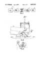
- FIG. 1Ais a side elevation section of the camera and monitor utilized to amplify a vein in an arm for manipulation of a needle to the vein;
- FIG. 1Bis a perspective illustrating a technician utilizing the apparatus in FIG. 1A to locate a vein.
- FIG. 2is a block diagram of the invention
- FIG. 3is a block diagram of the video processor circuit
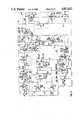
- FIG. 4is a diagram of an actual circuit utilized to practice the invention.
- a conventional video display D having a monitor screen Mis illustrated.
- the screenis observed by an observer at eye E through a lens system 14.
- a mirror 16deflects an image through an infrared bandpass filter F to a video camera C.
- Video camera Cincludes a charged coupled device 20 with a lens system 22.
- a coherent optical fiber bundlecan be used for imaging into the plane of the charged-coupled-device.
- An appendage A having a vein Vis illustrated. Illumination occurs from a light source L, schematically shown.
- monitor screen M of display Dimmediately overlies the real-world location of the vein V.
- the lens 14projects the screen and its image of the vein, as seen by the observer at position E, into the same plane in space as the actual vein and appendage. This enables a technician manipulating a needle to see in real spatial alignment a two-dimensional picture of the needle and vein without parallax error.
- the size of the image on Mcan be chosen such that the projected image as seen from E will be full size, after magnification by lens 14. Substantial assistance of manipulating the needle with respect to the vein results.
- FIG. 2a block diagram is shown.
- light Lpreferably a regular incandescent bulb
- the lightpasses through an infrared filter F to an infrared sensitive video camera C.
- the signalthereafter is passed through a processing circuit P to a video display D. It is the video display D which shows the site.
- a sync separator 30strips out a sync signal. It passes the stripped signal to a timing generator 32.
- the generatoroutputs through video gate 34 and sync gate 36 signals. These respective signals are utilized to switch on and off amplification and processing to the video signal only with amplification of the sync and frame pulse being omitted.
- Respective video gatesare located at 40, 44, and 46. When either a video gate signal at 34 is detected or a sync gate signal at 36 is detected, operation of the amplifiers is switched out of the circuit output. However, when the absence of the video gate and sync gate signals is present, amplification as disclosed occurs.
- a so-called "crispener” amplifier 50is utilized. This amplifier supplies amplification in the range of five times. Moreover, it is operative to increase relative gain for the high frequency portion of the signal. Thus, when the scanning raster undergoes rapid high frequency excursion--as in coming across a relatively low contrast vein B in an appendage A--amplifier 50 enhances or renders sharper the signal.
- Variable gain at amplifier 60is provided for optimizing the gain to the particular patient.
- the enhanced contrastproduces an extremely unsuitable contrasted image (nearly black at some areas and nearly white at others) across the totality of the video picture because of variations in illumination or reflectance of the skin or optical system efficiency across the image. Accordingly, it is necessary to average the signal from top scan to bottom scan, to adjust the video background relative to the horizontal sweep and additionally to display contrasts beyond a limited range as the log of the resultant contrast signal.
- the average intensity of a preceding horizontal scan lineis remembered. This average intensity is fed back to the following video line. This intensity is used to modulate the intensity of the following line so that the average is maintained. Thus, the signal is prevented from having undesirable vertical contrasts.
- the signalvaries as the raster sweeps horizontally.
- the variation producedis typically at the edges or shoulders of the picture. Accordingly, the width of the shoulder adjustment is adjusted at left center adjustment 83 and right center adjustment 84.
- the amount of adjustment providedis adjusted at left adjustment 81 and at right adjustment 82.
- the backgroundis adjusted to a level where the contrasted image can be seen.
- a divided by three attenuator 90provides two functions. First, divide by three attenuator 90 includes a soft clamp of the resultant video signal to give brightness proportional to the logarithm of the enhanced contrast produced by amplifiers 50 and 60 when it exceeds the linear range for display by the monitors. Secondly, the resultant signal is reduced in intensity so that the video signal having the right contrast range for display at the monitor is provided.
- This attenuator 100also includes a hard clamp which clamps the excursion of the video signal sufficiently below an excursion which would be recognized as either an end of frame or sync signal. By such clamping, a video signal is produced which can be played to a monitor.
- a sync restorer gate 110is utilized. Gate 110 puts back into the amplified and processed signal the video and sync gating required for monitor display.
- the video processor circuit hereis shown connecting a conventional camera to a conventional monitor. If the camera and monitor here disclosed is to be integrally designed, the video portion of the camera signal would not have the sync pulses added to the video portion, until full image processing had occurred or the sync signal would be fed by a separate wire to the monitor sync circuit. Here, however, because a camera that adds sync pulses is utilized, it is necessary to strip the signal during amplification. Likewise, and because a conventional monitor is used, it is required to add the sync signal back immediately before the signal is played at the monitor.
- the video gate 40is illustrated having an analog switch 141.
- Crispener amplifier 50is shown having a high frequency bandpass capacitor at 151 with an amplifier at 152.
- Amplification connections illustratedare conventional.
- Video gate 44has an analog switch 142.
- Variable gain amplifier 60includes a variable gain control 161.
- Divide by three circuit 90includes variable potentiometer 191 for setting the soft clamp level and 192 for adjustment of the clamp rate about the desired logarithmic function.
- Divide by two attenuator 100includes a variable pot 101 for setting the level of the hard clamp for prevention of an amplified pulse from being confused with a sync pulse.
- Sync restorer gate 110is again an analog switch. The switching here is phased to allow the sync pulse to pass out of the circuit.
- the video compensator 80includes potentiometer 81, 82 for adjustment of the intensity of the edge correction.
- the edge width itselfis adjusted by the respective potentiometers 83, 84.
- Circuit 70is a conventional circuit for comparison of the average intensity of an overlying horizontal scan to a current horizontal scan. Output to the divide by three attenuator at 90 occurs.
- the disclosed signal processing techniqueis exemplary.
- the enhancement of the contrast herein providedcould be over a limited brightness range.
- areas of contrastcan be enhanced.
- image enhancementcan be provided by a crispener circuit or differentiator circuit which could be tuned to enhance areas differing in brightness.
- tuning of the image producedcan result in resolution displaying the desired vascular structure.
- illumination of the subject by infrared light of differing wavelengths with subtraction of the brightness signal resulting from illumination at one wavelength from the signal produced by illumination at the other wavelengthcan occur.
- the ratios of brightness between the two wavelengths at each point in the picturecan be compared and displayed on the monitor.
- illuminationmay be moved to deeper region in the body.
- a fiber optic bundle placed in contact with the skincan be utilized to guide the illuminating infrared energy.
- This fiber optic bundlewill illuminate relatively deep vascular structures, which surface illumination would not reach. This would reduce surface scattering of IR which occurs when a bulb is used to illuminate the surface, and can improve image contrast.
- This deviceis well adapted for diverse uses in medical examinations, such as examination of the middle ear behind the ear drum, which is transparent to near infrared of appropriate wavelength. Other applications include examination of the subsurface structure of the mucous membrane surfaces such as nose, mouth, throat, trachea, esophagus, stomach, etc., and vagina and rectum.
- This devicecan be adapted for use as a real time infrared ophthalmoscope for examining behind the retina and for viewing the eye interior through cataracts.
Landscapes
- Health & Medical Sciences (AREA)
- Life Sciences & Earth Sciences (AREA)
- Heart & Thoracic Surgery (AREA)
- Medical Informatics (AREA)
- Biophysics (AREA)
- Pathology (AREA)
- Engineering & Computer Science (AREA)
- Biomedical Technology (AREA)
- Veterinary Medicine (AREA)
- Physics & Mathematics (AREA)
- Molecular Biology (AREA)
- Surgery (AREA)
- Animal Behavior & Ethology (AREA)
- General Health & Medical Sciences (AREA)
- Public Health (AREA)
- Vascular Medicine (AREA)
- Closed-Circuit Television Systems (AREA)
- Measuring And Recording Apparatus For Diagnosis (AREA)
Abstract
Description
This invention relates to a simple, medical electronic device for viewing infrared absorption contrast under the skin. Simply stated, a TV camera and monitor is disclosed for viewing hard to find vascular structure for insertion of needles.
Veins and arteries in many patients are hard to find. When dehydrated patients, dark-skin patients, and young patients are treated, finding the veins and arteries is a classic medical problem involving pain, stress and distress. Further, unskilled technicians have grave difficulty in locating many subcutaneous structures in even normal patients. Thus, an aid in locating such structures is needed.
The use of infrared photography for visualizing subcutaneous veins, arteries and structures has been known for many years. These systems make use of the penetration of the near infrared rays into the skin, and the preferential absorption of the near infrared rays by the molecules in the vascular system. Consequently, a low contrast infrared image can be produced.
Heretofore, this technique has only been used with photography.
Part of the human body or appendage, for example the inside of the elbow, is illuminated with an infrared source, for example, at least one incandescent light bulb. A video camera for producing a video image and immediately overlying monitor for repeating the video image is utilized to look at the flesh. The video camera is sensitive to infrared radiation. If the camera is also sensitive to visible light, an infrared passing filter which stops visible light may be interposed. A video display results in which infrared contrasts in portions of the flesh are highlighted, for example, hard to find veins for insertions of needles. A contrast enhancing circuit is included which discloses amplifying the video information with high contrast enhancement of the video signal. Adaptation of the disclosed circuit to conventional CCD cameras and monitors is illustrated with compensation of horizontal sweep to even out image background, intensity averaging line to line for vertical image uniformity and display of image contrasts on a non-linear scale.
An object of this invention is to disclose a process for finding infrared contrast differentiated structure in the flesh, for example veins in human appendages such as the inside elbow of the arm. A source of infrared illumination is provided, which for example can be a regular incandescent bulb, or an infrared light emitting diode or laser. An infrared sensitive video camera and immediately overlying video monitor for displaying the image from the camera is used. The video signal is enhanced as to contrast to display the underlying infrared absorption or scattering differentiated structure.
An advantage of the disclosed process and apparatus is that it is specifically suited for finding veins and arteries. Moreover, relative movement of a needle tip to a vein or artery is easily observed.
A further object of this invention is to disclose a process of video signal enhancement of an infrared image showing vascular structure. Simply, the video portion of the signal is amplified with an enhanced contrast output. Thereafter, the sync signal is added and played at a monitor to disclose the infrared absorption differentiated area. For example, veins in appendages can be clearly shown.
Yet another object of this invention is to disclose adjustments that can adapt conventional silicon CCD cameras and monitors to portray enhanced contrast images. According to this aspect of the invention the sync pulses are stripped. Amplification occurs and the sync pulses are restored. The signal level along each horizontal scan line is compensated for variations in the background, typically near the beginning and the end of the scan line. Vertical intensity averaging is utilized with each line being intensity averaged and being utilized to control the intensity of at least the following line. Enhanced contrast is displayed within a limited linear range, outside of which range the log of the amplified high contrast image is displayed. Moreover, the total brightness excursion provided is clamped to prevent "false" sync pulses. A coherent signal capable of displaying an enhanced infrared image results.
Over photography, the disclosed infrared video technique can be used in real time to study subjects at the infrared wavelengths. More importantly, the contrast enhancing technique possible with video signal processing includes a dynamic range and signal to noise ratio far superior to infrared photography. Coupled with the real time aspect of this invention, a superior apparatus and process is disclosed.
Other objects, features and advantages of this invention can become more apparent after referring to the following specification and attached drawings in which:
FIG. 1A is a side elevation section of the camera and monitor utilized to amplify a vein in an arm for manipulation of a needle to the vein;
FIG. 1B is a perspective illustrating a technician utilizing the apparatus in FIG. 1A to locate a vein.
FIG. 2 is a block diagram of the invention;
FIG. 3 is a block diagram of the video processor circuit; and,
FIG. 4 is a diagram of an actual circuit utilized to practice the invention.
Referring to FIGS. 1A and 1B, a conventional video display D having a monitor screen M is illustrated. The screen is observed by an observer at eye E through alens system 14. A mirror 16 deflects an image through an infrared bandpass filter F to a video camera C. It will be understood that the video camera C is conventional. Video camera C includes a charged coupleddevice 20 with alens system 22. As an alternative to thelens 22, a coherent optical fiber bundle can be used for imaging into the plane of the charged-coupled-device. An appendage A having a vein V is illustrated. Illumination occurs from a light source L, schematically shown.
It will be seen that monitor screen M of display D immediately overlies the real-world location of the vein V. Thelens 14 projects the screen and its image of the vein, as seen by the observer at position E, into the same plane in space as the actual vein and appendage. This enables a technician manipulating a needle to see in real spatial alignment a two-dimensional picture of the needle and vein without parallax error. The size of the image on M can be chosen such that the projected image as seen from E will be full size, after magnification bylens 14. Substantial assistance of manipulating the needle with respect to the vein results.
The reader will understand that here we show a video display D. The image could likewise be recorded and stored for record purposes.
Referring to FIG. 2 a block diagram is shown. Typically light L (preferably a regular incandescent bulb) illuminates the appendage A of the subject. The light passes through an infrared filter F to an infrared sensitive video camera C. The signal thereafter is passed through a processing circuit P to a video display D. It is the video display D which shows the site.
Having set forth this much, the circuit of FIG. 3 can be easily understood. Async separator 30 strips out a sync signal. It passes the stripped signal to atiming generator 32. The generator outputs throughvideo gate 34 andsync gate 36 signals. These respective signals are utilized to switch on and off amplification and processing to the video signal only with amplification of the sync and frame pulse being omitted. Respective video gates are located at 40, 44, and 46. When either a video gate signal at 34 is detected or a sync gate signal at 36 is detected, operation of the amplifiers is switched out of the circuit output. However, when the absence of the video gate and sync gate signals is present, amplification as disclosed occurs.
A so-called "crispener"amplifier 50 is utilized. This amplifier supplies amplification in the range of five times. Moreover, it is operative to increase relative gain for the high frequency portion of the signal. Thus, when the scanning raster undergoes rapid high frequency excursion--as in coming across a relatively low contrast vein B in an appendage A--amplifier 50 enhances or renders sharper the signal.
Variable gain atamplifier 60 is provided for optimizing the gain to the particular patient.
Stopping here, and with conventional TV cameras and monitors, it has been found that the enhanced contrast produces an extremely unsuitable contrasted image (nearly black at some areas and nearly white at others) across the totality of the video picture because of variations in illumination or reflectance of the skin or optical system efficiency across the image. Accordingly, it is necessary to average the signal from top scan to bottom scan, to adjust the video background relative to the horizontal sweep and additionally to display contrasts beyond a limited range as the log of the resultant contrast signal.
Referring tocircuit 70, the average intensity of a preceding horizontal scan line is remembered. This average intensity is fed back to the following video line. This intensity is used to modulate the intensity of the following line so that the average is maintained. Thus, the signal is prevented from having undesirable vertical contrasts.
Additionally, it has been found that the signal varies as the raster sweeps horizontally. The variation produced is typically at the edges or shoulders of the picture. Accordingly, the width of the shoulder adjustment is adjusted atleft center adjustment 83 andright center adjustment 84. The amount of adjustment provided is adjusted atleft adjustment 81 and atright adjustment 82. Thus, the background is adjusted to a level where the contrasted image can be seen.
A divided by threeattenuator 90 provides two functions. First, divide by threeattenuator 90 includes a soft clamp of the resultant video signal to give brightness proportional to the logarithm of the enhanced contrast produced byamplifiers
Additionally, a divide by twoattenuator 100 is utilized. This attenuator also includes a hard clamp which clamps the excursion of the video signal sufficiently below an excursion which would be recognized as either an end of frame or sync signal. By such clamping, a video signal is produced which can be played to a monitor.
Finally, and after signal processing, async restorer gate 110 is utilized.Gate 110 puts back into the amplified and processed signal the video and sync gating required for monitor display.
Those having skill in the video arts will recognized that the video processor circuit here is shown connecting a conventional camera to a conventional monitor. If the camera and monitor here disclosed is to be integrally designed, the video portion of the camera signal would not have the sync pulses added to the video portion, until full image processing had occurred or the sync signal would be fed by a separate wire to the monitor sync circuit. Here, however, because a camera that adds sync pulses is utilized, it is necessary to strip the signal during amplification. Likewise, and because a conventional monitor is used, it is required to add the sync signal back immediately before the signal is played at the monitor.
Turning to FIG. 4, the actual fabrication of the enhancement circuit can now be easily understood.
Referring to FIG. 4 thevideo gate 40 is illustrated having ananalog switch 141.Crispener amplifier 50 is shown having a high frequency bandpass capacitor at 151 with an amplifier at 152. Amplification connections illustrated are conventional.Video gate 44 has an analog switch 142.
Divide by threecircuit 90 includesvariable potentiometer 191 for setting the soft clamp level and 192 for adjustment of the clamp rate about the desired logarithmic function.
Divide by twoattenuator 100 includes a variable pot 101 for setting the level of the hard clamp for prevention of an amplified pulse from being confused with a sync pulse.
Thevideo compensator 80 includespotentiometer respective potentiometers
It will be understood that the disclosed signal processing technique is exemplary. For example, the enhancement of the contrast herein provided could be over a limited brightness range. By the expedient of adjusting the brightness to a uniform level, areas of contrast can be enhanced.
Similarly, image enhancement can be provided by a crispener circuit or differentiator circuit which could be tuned to enhance areas differing in brightness. Thus, tuning of the image produced can result in resolution displaying the desired vascular structure.
Likewise, illumination of the subject by infrared light of differing wavelengths with subtraction of the brightness signal resulting from illumination at one wavelength from the signal produced by illumination at the other wavelength can occur. Alternately, and by using by light of differing wavelengths, the ratios of brightness between the two wavelengths at each point in the picture can be compared and displayed on the monitor.
Moreover, illumination may be moved to deeper region in the body. For example, a fiber optic bundle placed in contact with the skin (or in a body cavity or oriface) can be utilized to guide the illuminating infrared energy. This fiber optic bundle will illuminate relatively deep vascular structures, which surface illumination would not reach. This would reduce surface scattering of IR which occurs when a bulb is used to illuminate the surface, and can improve image contrast.
Furthermore, pressure on the skin will collapse veins and empty them of blood, thus applying and removing pressure and subtracting the two images taken with and without pressure can enhance visibility of the veins in the image.
This device is well adapted for diverse uses in medical examinations, such as examination of the middle ear behind the ear drum, which is transparent to near infrared of appropriate wavelength. Other applications include examination of the subsurface structure of the mucous membrane surfaces such as nose, mouth, throat, trachea, esophagus, stomach, etc., and vagina and rectum. This device can be adapted for use as a real time infrared ophthalmoscope for examining behind the retina and for viewing the eye interior through cataracts.
We have illustrated the particular circuit here shown as a preferred embodiment. However, the enhancement of the infrared image to which we refer includes any of the above apparatus, the present method being preferred because of reduction of practice.
Claims (11)
1. Apparats for producing an enhanced contrast infrared image of the flesh for viewing subcutaneous structures such as veins in flesh illuminated with light which includes infrared light, said apparatus comprising:
light source means including means for providing infrared light and adapted to illuminate a portion of flesh so as to produce an image of said flesh from differential absorption of said infrared light on said flesh;
video camera means adapted to receive an image of said differentially absorbed infrared light on said illuminated flesh and output a video signal;
monitor means for playing back from said outputted video signal the image of said illuminated flesh; and,
circuit means connecting said video camera means and said monitor means for producing an enhanced contrast image of said flesh in real time whereby said image from said differential absorption of infrared light has the contrast enhanced to view subcutaneous structure such as veins.
2. The apparatus of claim 1 and wherein said monitor means is located immediately overlying said camera means and oriented to display said image away from said camera means whereby said image in said monitor means overlies said flesh in space.
3. The apparatus of claim 1 wherein said circuit means includes means for generating successive horizontal scans and further includes means for vertically averaging the intensity of each horizontal scan to the intensity of at least one horizontal scan.
4. The apparatus of claim 3 and wherein said circuit means includes means for adjusting the background of said horizontal scans with respect to a corresponding scan of said camera means and monitor means.
5. The apparatus of claim 1 and wherein said circuit means includes means for amplifying the video signal of said camera profiled to a log output.
6. The invention of claim 5 and wherein said circuit means includes means for passing to high amplification, high frequency contrast signals in said video signal.
7. A process for viewing infrared absorbing or scattering structures in flesh, such as veins, comprising
illuminating said flesh with an infrared light source to produce differential infrared absorption of infrared light;
taking an infrared video image, using a video camera, of said infrared illuminated flesh to produce a differential infrared absorption image of said illuminated flesh on a monitor;
outputting a video signal of said differential infrared absorption image of said illuminated flesh;
providing enhanced contrast amplification to the video signal derived from the infrared image of said flesh; and,
playing back the video image of said flesh on a monitor to produce a high contrast visible image of infrared absorbing or scattering structures in said flesh in real time.
8. The process of claim 7 and including the step of positioning said monitor immediately overlying said camera and orienting said monitor to display said image away from said camera and the flesh whereby said image in said monitor overlies said flesh in space.
9. The process of claim 7 and including amplifying said video signal by preferably amplifying high frequency portions of said video signal to enhance said infrared absorbing or scattering structures.
10. The process of claim 7 and including in said amplification step vertically averaging each line of said video signal with respect to a previous line of said video signal.
11. The process of claim 7 and including in said amplification step adjustment of the horizontal background of said scan.
Priority Applications (1)
| Application Number | Priority Date | Filing Date | Title |
|---|---|---|---|
| US06/888,916US4817622A (en) | 1986-07-22 | 1986-07-22 | Infrared imager for viewing subcutaneous location of vascular structures and method of use |
Applications Claiming Priority (1)
| Application Number | Priority Date | Filing Date | Title |
|---|---|---|---|
| US06/888,916US4817622A (en) | 1986-07-22 | 1986-07-22 | Infrared imager for viewing subcutaneous location of vascular structures and method of use |
Publications (1)
| Publication Number | Publication Date |
|---|---|
| US4817622Atrue US4817622A (en) | 1989-04-04 |
Family
ID=25394164
Family Applications (1)
| Application Number | Title | Priority Date | Filing Date |
|---|---|---|---|
| US06/888,916Expired - LifetimeUS4817622A (en) | 1986-07-22 | 1986-07-22 | Infrared imager for viewing subcutaneous location of vascular structures and method of use |
Country Status (1)
| Country | Link |
|---|---|
| US (1) | US4817622A (en) |
Cited By (104)
| Publication number | Priority date | Publication date | Assignee | Title |
|---|---|---|---|---|
| US4995398A (en)* | 1990-04-30 | 1991-02-26 | Turnidge Patrick A | Coronary angiography imaging system |
| US5267331A (en)* | 1990-07-26 | 1993-11-30 | Ronald Siwoff | Digitally enhanced imager for the visually impaired |
| US5311018A (en)* | 1993-02-11 | 1994-05-10 | The United States Of America As Represented By The Secretary Of The Air Force | Optical system for obtaining separate and simultaneous near-infrared and visible light images |
| US5519208A (en)* | 1994-09-29 | 1996-05-21 | Esparza; Joel | Infrared aided method and apparatus for venous examination |
| WO1996029826A1 (en)* | 1995-03-20 | 1996-09-26 | Northrop Grumman Corporation | Filtered auxiliary illumination of surveillance area |
| WO1996039925A1 (en)* | 1995-06-07 | 1996-12-19 | University Of Arkansas | Method and apparatus for detecting electro-magnetic reflection from biological tissue |
| WO1996036273A3 (en)* | 1995-05-16 | 1996-12-19 | Us Air Force | System and method for enhanced visualization of subcutaneous structures |
| WO1996041481A1 (en)* | 1995-06-07 | 1996-12-19 | Stryker Corporation | Imaging system with independent processing of visible and infrared light energy |
| US5608210A (en)* | 1994-09-29 | 1997-03-04 | Esparza; Joel | Infrared aided method and apparatus for venous examination |
| US5699797A (en)* | 1992-10-05 | 1997-12-23 | Dynamics Imaging, Inc. | Method of investigation of microcirculation functional dynamics of physiological liquids in skin and apparatus for its realization |
| US5730133A (en)* | 1994-05-20 | 1998-03-24 | Dynamics Imaging, Inc. | Optical functional mamoscope |
| US5747789A (en)* | 1993-12-01 | 1998-05-05 | Dynamics Imaging, Inc. | Method for investigation of distribution of physiological components in human body tissues and apparatus for its realization |
| US5769784A (en)* | 1995-11-27 | 1998-06-23 | Hill-Rom, Inc. | Skin perfusion evaluation apparatus and method |
| US5788639A (en)* | 1995-07-13 | 1998-08-04 | Lucid Technologies, Inc. | Confocal imaging through thick dermal tissue |
| WO1998044841A1 (en)* | 1997-04-09 | 1998-10-15 | Ugnell Haakan | Device for optic identification of blood vessels |
| US5865167A (en)* | 1991-12-17 | 1999-02-02 | Dynamics Imaging, Inc. | Method of living system organism diagnostics and apparatus for its realization |
| US5865743A (en)* | 1994-02-23 | 1999-02-02 | Dynamics Imaging, Inc. | Method of living organism multimodal functional mapping |
| US5865829A (en)* | 1992-06-15 | 1999-02-02 | Kabushiki Kaisha Topcon | Medical optical apparatus |
| US5910816A (en)* | 1995-06-07 | 1999-06-08 | Stryker Corporation | Imaging system with independent processing of visible an infrared light energy |
| US5947906A (en)* | 1997-11-14 | 1999-09-07 | Dawson, Jr.; Fredric O. | Apparatus for enhanced visual venous examination |
| WO1999048420A1 (en) | 1998-03-23 | 1999-09-30 | Veino-Med Ltd. | Instrument and method for locating and marking a 'hot spot' in a person's body tissue |
| US5997472A (en)* | 1995-04-14 | 1999-12-07 | Vipera Systems, Inc. | Endodiagnostic method using differential thermal relaxation and IR imaging |
| US6002958A (en)* | 1992-12-24 | 1999-12-14 | Dynamics Imaging, Inc. | Method and apparatus for diagnostics of internal organs |
| US6178340B1 (en)* | 1998-08-24 | 2001-01-23 | Eduardo Svetliza | Three-dimensional infrared imager for subcutaneous puncture and study of vascular network |
| US6192262B1 (en) | 1994-02-23 | 2001-02-20 | Dobi Medical Systems, Llc | Method of living organism multimodal functional mapping |
| US6263233B1 (en) | 1995-07-13 | 2001-07-17 | Lucid, Inc. | Handheld imaging microscope |
| US6270464B1 (en) | 1998-06-22 | 2001-08-07 | Artemis Medical, Inc. | Biopsy localization method and device |
| US20010034528A1 (en)* | 1994-09-16 | 2001-10-25 | Foerster Seth A. | Methods and devices for defining and marking tissue |
| US6336904B1 (en) | 1998-04-07 | 2002-01-08 | Pro Duct Health, Inc. | Methods and devices for the localization of lesions in solid tissue |
| US6353753B1 (en) | 1998-05-05 | 2002-03-05 | Stephen Thomas Flock | Optical imaging of deep anatomic structures |
| US6424858B1 (en)* | 1998-11-12 | 2002-07-23 | John L. Williams | Apparatus and method for viewing vasculature of a human being |
| US6463309B1 (en) | 2000-05-11 | 2002-10-08 | Hanna Ilia | Apparatus and method for locating vessels in a living body |
| US6488623B1 (en) | 2000-11-09 | 2002-12-03 | Hill-Rom Services, Inc. | Skin perfusion evaluation apparatus |
| US6522911B1 (en)* | 1998-11-20 | 2003-02-18 | Fuji Photo Film Co., Ltd. | Apparatus for imaging a blood vessel |
| US6529617B1 (en)* | 1996-07-29 | 2003-03-04 | Francine J. Prokoski | Method and apparatus for positioning an instrument relative to a patients body during a medical procedure |
| US6556858B1 (en) | 2000-01-19 | 2003-04-29 | Herbert D. Zeman | Diffuse infrared light imaging system |
| US20030210810A1 (en)* | 2002-05-08 | 2003-11-13 | Gee, James W. | Method and apparatus for detecting structures of interest |
| US20040015158A1 (en)* | 2002-07-19 | 2004-01-22 | To-Mu Chen | Transilluminator device |
| US20040111030A1 (en)* | 2000-01-19 | 2004-06-10 | Zeman Herbert D. | Imaging system using diffuse infrared light |
| US20040171923A1 (en)* | 2002-12-06 | 2004-09-02 | Kalafut John F. | Devices, systems and methods for improving vessel access |
| US20040215081A1 (en)* | 2003-04-23 | 2004-10-28 | Crane Robert L. | Method for detection and display of extravasation and infiltration of fluids and substances in subdermal or intradermal tissue |
| AU2002300219B2 (en)* | 1995-06-07 | 2004-11-25 | University Of Arkansas | Method and Apparatus for Detecting Electro-magnetic Reflection from Biological Tissue |
| US20040267155A1 (en)* | 1998-06-22 | 2004-12-30 | Fulton Richard Eustis | Biopsy localization method and device |
| US20050033145A1 (en)* | 2003-07-02 | 2005-02-10 | Graham John S. | Wearable tissue viability diagnostic unit |
| US20050101871A1 (en)* | 1995-07-13 | 2005-05-12 | James Zavislan | Microscopic imaging apparatus and method |
| US20050203440A1 (en)* | 2004-03-11 | 2005-09-15 | Gellman Barry N. | System and method for tissue sampling and therapeutic treatment |
| US20060020212A1 (en)* | 2004-07-26 | 2006-01-26 | Tianning Xu | Portable vein locating device |
| US20060122515A1 (en)* | 2000-01-19 | 2006-06-08 | Luminetx Corporation | Projection of subsurface structure onto an object's surface |
| WO2006069066A2 (en) | 2004-12-22 | 2006-06-29 | Syris Scientific, Llc | System and method for locating and accessing a blood vessel |
| US20060173360A1 (en)* | 2005-01-07 | 2006-08-03 | Kalafut John F | Method for detection and display of extravasation and infiltration of fluids and substances in subdermal or intradermal tissue |
| WO2007005018A1 (en)* | 2005-07-01 | 2007-01-11 | Luminetx Technologies Corporation | Projection of subsurface structure onto an object's surface |
| US20070032721A1 (en)* | 2005-05-13 | 2007-02-08 | Crane Robert L | Disposable Light Source Patch for Enhanced Visualization of Subcutaneous Structures |
| GB2429130A (en)* | 2005-08-10 | 2007-02-14 | Avago Tech Ecbu Ip | Imaging subcutaneous tissue |
| US20070161906A1 (en)* | 2000-01-19 | 2007-07-12 | Luminetx Technologies Corporation | Method To Facilitate A Dermatological Procedure |
| US20070161907A1 (en)* | 2006-01-10 | 2007-07-12 | Ron Goldman | Micro vein enhancer |
| US20070158569A1 (en)* | 2000-01-19 | 2007-07-12 | Luminetx Technologies Corporation | Method and Apparatus for Projection of Subsurface Structure onto an Object's Surface |
| US20070255097A1 (en)* | 2006-04-28 | 2007-11-01 | Searete Llc, A Limited Liability Corporation Of The State Of Delaware | Imaging via blood vessels |
| US20070253614A1 (en)* | 2006-04-28 | 2007-11-01 | Searete Llc, A Limited Liability Corporation Of The State Of Delaware | Artificially displaying information relative to a body |
| US20070276258A1 (en)* | 2006-03-28 | 2007-11-29 | Crane Robert L | Synchronization of Illumination Source and Sensor for Improved Visualization of Subcutaneous Structures |
| US20080004525A1 (en)* | 2006-01-10 | 2008-01-03 | Ron Goldman | Three dimensional imaging of veins |
| US20080027317A1 (en)* | 2006-06-29 | 2008-01-31 | Fred Wood | Scanned laser vein contrast enhancer |
| US20080045818A1 (en)* | 2006-06-29 | 2008-02-21 | Fred Wood | Laser vein contrast enhancer |
| EP1925961A2 (en) | 1997-06-30 | 2008-05-28 | Lucid, Inc. | Confocal imaging through thick dermal tissues |
| US20080162217A1 (en)* | 2004-06-14 | 2008-07-03 | Symphonyrpm, Inc. | Decision object for associating a plurality of business plans |
| US20080177174A1 (en)* | 2006-10-11 | 2008-07-24 | Crane Robert L | Determining Inserted Catheter End Location and Orientation |
| US20080177184A1 (en)* | 2006-06-29 | 2008-07-24 | Ron Goldman | Micro vein enhancer |
| WO2008098241A1 (en)* | 2007-02-09 | 2008-08-14 | Vustik, Inc. | Infrared-visible needle |
| US20080243076A1 (en)* | 2005-07-11 | 2008-10-02 | Simon Fraser University | Method and Apparatus For Venipuncture Site Location |
| US20090002488A1 (en)* | 2007-06-28 | 2009-01-01 | Vincent Luciano | Automatic alignment of a contrast enhancement system |
| US20090018414A1 (en)* | 2007-03-23 | 2009-01-15 | Mehrdad Toofan | Subcutanous Blood Vessels Imaging System |
| WO2009049633A1 (en)* | 2007-10-17 | 2009-04-23 | Novarix Ltd. | Vein navigation device |
| US20100177182A1 (en)* | 2006-04-07 | 2010-07-15 | Novarix Ltd | Vein navigation device |
| US20100274202A1 (en)* | 2009-04-28 | 2010-10-28 | Searete Llc | Systems and methods for automatically inserting a needle into a living subject |
| US20110009751A1 (en)* | 2009-07-13 | 2011-01-13 | Mcguire Jr James E | Subcutaneous access device and related methods |
| US20110021925A1 (en)* | 2006-06-29 | 2011-01-27 | Fred Wood | Mounted vein contrast enchancer |
| US20110112407A1 (en)* | 2006-06-29 | 2011-05-12 | Fred Wood | Multispectral detection and presentation of an object's characteristics |
| US20110118611A1 (en)* | 2006-06-29 | 2011-05-19 | Vincent Luciano | Module mounting mirror endoscopy |
| US20110125028A1 (en)* | 2009-07-22 | 2011-05-26 | Fred Wood | Vein scanner |
| US20110313294A1 (en)* | 2008-11-18 | 2011-12-22 | Umc Utrecht Holding B.V. | Apparatus and method for determining the position of a vein or artery |
| EP2412313A1 (en) | 2005-01-03 | 2012-02-01 | Syris Scientific LLC | System and method for inserting a needle into a blood vessel |
| EP2540214A1 (en) | 2011-06-28 | 2013-01-02 | Christie Digital Systems USA, Inc. | Apparatus for detection of catheter location for intravenous access |
| DE102011121020B3 (en)* | 2011-12-13 | 2013-01-31 | Jan Dreyer | Subcutaneous vessel representation device for contactless location of warm skin region on surface, measures/compares temperature of larger measuring range and smaller measuring range enclosed by larger measuring range in circular form |
| US20150094662A1 (en)* | 2013-10-02 | 2015-04-02 | Korea Institute Of Science And Technology | Visualization apparatus for vein |
| WO2015059636A1 (en) | 2013-10-23 | 2015-04-30 | Insono S.R.L. | Device for non-invasive detection of predetermined biological structures |
| US9061109B2 (en) | 2009-07-22 | 2015-06-23 | Accuvein, Inc. | Vein scanner with user interface |
| US9117133B2 (en) | 2008-06-18 | 2015-08-25 | Spectral Image, Inc. | Systems and methods for hyperspectral imaging |
| US9492117B2 (en) | 2006-01-10 | 2016-11-15 | Accuvein, Inc. | Practitioner-mounted micro vein enhancer |
| US9572530B2 (en) | 2010-03-19 | 2017-02-21 | Quickvein, Inc. | Apparatus and methods for imaging blood vessels |
| US9782079B2 (en) | 2012-08-02 | 2017-10-10 | Accuvein, Inc. | Device for detecting and illuminating the vasculature using an FPGA |
| US9854977B2 (en) | 2006-01-10 | 2018-01-02 | Accuvein, Inc. | Scanned laser vein contrast enhancer using a single laser, and modulation circuitry |
| US10062356B1 (en) | 2008-09-30 | 2018-08-28 | The United States of America as Represented by the Admin of National Aeronautics and Space Administration | Two and three dimensional near infrared subcutaneous structure imager using real time nonlinear video processing |
| US10238294B2 (en) | 2006-06-29 | 2019-03-26 | Accuvein, Inc. | Scanned laser vein contrast enhancer using one laser |
| US10376147B2 (en) | 2012-12-05 | 2019-08-13 | AccuVeiw, Inc. | System and method for multi-color laser imaging and ablation of cancer cells using fluorescence |
| US10813588B2 (en) | 2006-01-10 | 2020-10-27 | Accuvein, Inc. | Micro vein enhancer |
| US10977776B1 (en)* | 2008-09-30 | 2021-04-13 | United States Of America As Represented By The Administrator Of National Aeronautics And Space Administration | Two and three-dimensional near infrared subcutaneous structure imager using realtime nonlinear video processing |
| RU204680U1 (en)* | 2021-02-09 | 2021-06-04 | Общество с ограниченной ответственностью "БИОСПЕК" | DEVICE FOR CONTACT INFRARED VISUALIZATION OF BLOOD VESSELS BY BACKSCATTERED LASER RADIATION |
| US11207024B2 (en)* | 2017-07-12 | 2021-12-28 | Boe Technology Group Co., Ltd. | Vascular imaging apparatus and vascular imaging method |
| US11253198B2 (en) | 2006-01-10 | 2022-02-22 | Accuvein, Inc. | Stand-mounted scanned laser vein contrast enhancer |
| US11278240B2 (en) | 2006-01-10 | 2022-03-22 | Accuvein, Inc. | Trigger-actuated laser vein contrast enhancer |
| CN116509329A (en)* | 2023-04-24 | 2023-08-01 | 浙江大学 | A venipuncture device based on infrared scanning imaging technology |
| US12048560B2 (en) | 2006-01-10 | 2024-07-30 | Accuvein, Inc. | Vein scanner configured for single-handed lifting and use |
| US12220255B2 (en) | 2020-07-30 | 2025-02-11 | Novotec Llc | Vessel location assistance device |
| US12295744B2 (en) | 2006-01-10 | 2025-05-13 | Accuvein, Inc. | Micro vein enhancer with two lasers and two optical detectors configured for removing surface topology |
| US12408865B2 (en) | 2006-01-10 | 2025-09-09 | Accuvein Inc. | Vein imaging device with differential image resolution at the center and the extremities of the vein image |
Citations (19)
| Publication number | Priority date | Publication date | Assignee | Title |
|---|---|---|---|---|
| US3566669A (en)* | 1968-09-04 | 1971-03-02 | Harry Parker | Method and apparatus for thermally examining fluid passages in a body |
| US3583223A (en)* | 1967-09-26 | 1971-06-08 | Bofors Ab | Infrared television system for temperature measurement |
| US3635085A (en)* | 1968-06-15 | 1972-01-18 | Nippon Kokan Kk | System for detecting the temperature distribution of a heated body |
| US3798366A (en)* | 1972-03-06 | 1974-03-19 | R Winkler | Infrared imaging system |
| US3845326A (en)* | 1972-09-01 | 1974-10-29 | W Godden | Logarithmic amplification circuit |
| US3969571A (en)* | 1974-11-09 | 1976-07-13 | Medicor Muvek | System for improving the evaluation of pictures comprising details hard to recognize, mainly of fluorographs and radiographs |
| US3980819A (en)* | 1974-11-01 | 1976-09-14 | Zenith Radio Corporation | Edge enhancement for television images |
| US4063093A (en)* | 1976-11-22 | 1977-12-13 | Barnes Engineering Company | Infrared vidicon system |
| US4080532A (en)* | 1975-12-29 | 1978-03-21 | Texas Instruments Incorporated | Ferroelectric imaging system |
| US4323973A (en)* | 1979-12-20 | 1982-04-06 | Greenfield George B | Apparatus and method for enhancing radiographs |
| US4328516A (en)* | 1980-11-17 | 1982-05-04 | The United States Of America As Represented By The Secretary Of The Army | Integral test input for electro-optically multiplexed FLIR system |
| US4388729A (en)* | 1973-03-23 | 1983-06-14 | Dolby Laboratories, Inc. | Systems for reducing noise in video signals using amplitude averaging of undelayed and time delayed signals |
| US4527569A (en)* | 1982-11-26 | 1985-07-09 | South African Inventions Develop. Corp. | Device for guiding a surgical needle into a blood vessel |
| US4539593A (en)* | 1982-01-15 | 1985-09-03 | Institut National De La Sante Et De La Recherche Medicale | Apparatus for the acquisition and restoration in real time of a picture formed from successive frames of scanning lines |
| US4598314A (en)* | 1983-02-07 | 1986-07-01 | Robert Bosch Gmbh | Method and apparatus for converting a video signal to a corresponding signal of lower line count |
| US4618928A (en)* | 1982-12-06 | 1986-10-21 | Tokyo Shibaura Denki Kabushiki Kaisha | Data processing apparatus for producing X-ray images with improved signal to noise ratio |
| US4623923A (en)* | 1983-03-14 | 1986-11-18 | Honeywell Inc. | Real-time video image enhancement system |
| US4626905A (en)* | 1983-07-26 | 1986-12-02 | Ernst Leitz Wetzlar Gmbh | Panoramic view apparatus |
| US4652921A (en)* | 1984-07-27 | 1987-03-24 | Quantel Limited | Image processing apparatus |
- 1986
- 1986-07-22USUS06/888,916patent/US4817622A/ennot_activeExpired - Lifetime
Patent Citations (19)
| Publication number | Priority date | Publication date | Assignee | Title |
|---|---|---|---|---|
| US3583223A (en)* | 1967-09-26 | 1971-06-08 | Bofors Ab | Infrared television system for temperature measurement |
| US3635085A (en)* | 1968-06-15 | 1972-01-18 | Nippon Kokan Kk | System for detecting the temperature distribution of a heated body |
| US3566669A (en)* | 1968-09-04 | 1971-03-02 | Harry Parker | Method and apparatus for thermally examining fluid passages in a body |
| US3798366A (en)* | 1972-03-06 | 1974-03-19 | R Winkler | Infrared imaging system |
| US3845326A (en)* | 1972-09-01 | 1974-10-29 | W Godden | Logarithmic amplification circuit |
| US4388729A (en)* | 1973-03-23 | 1983-06-14 | Dolby Laboratories, Inc. | Systems for reducing noise in video signals using amplitude averaging of undelayed and time delayed signals |
| US3980819A (en)* | 1974-11-01 | 1976-09-14 | Zenith Radio Corporation | Edge enhancement for television images |
| US3969571A (en)* | 1974-11-09 | 1976-07-13 | Medicor Muvek | System for improving the evaluation of pictures comprising details hard to recognize, mainly of fluorographs and radiographs |
| US4080532A (en)* | 1975-12-29 | 1978-03-21 | Texas Instruments Incorporated | Ferroelectric imaging system |
| US4063093A (en)* | 1976-11-22 | 1977-12-13 | Barnes Engineering Company | Infrared vidicon system |
| US4323973A (en)* | 1979-12-20 | 1982-04-06 | Greenfield George B | Apparatus and method for enhancing radiographs |
| US4328516A (en)* | 1980-11-17 | 1982-05-04 | The United States Of America As Represented By The Secretary Of The Army | Integral test input for electro-optically multiplexed FLIR system |
| US4539593A (en)* | 1982-01-15 | 1985-09-03 | Institut National De La Sante Et De La Recherche Medicale | Apparatus for the acquisition and restoration in real time of a picture formed from successive frames of scanning lines |
| US4527569A (en)* | 1982-11-26 | 1985-07-09 | South African Inventions Develop. Corp. | Device for guiding a surgical needle into a blood vessel |
| US4618928A (en)* | 1982-12-06 | 1986-10-21 | Tokyo Shibaura Denki Kabushiki Kaisha | Data processing apparatus for producing X-ray images with improved signal to noise ratio |
| US4598314A (en)* | 1983-02-07 | 1986-07-01 | Robert Bosch Gmbh | Method and apparatus for converting a video signal to a corresponding signal of lower line count |
| US4623923A (en)* | 1983-03-14 | 1986-11-18 | Honeywell Inc. | Real-time video image enhancement system |
| US4626905A (en)* | 1983-07-26 | 1986-12-02 | Ernst Leitz Wetzlar Gmbh | Panoramic view apparatus |
| US4652921A (en)* | 1984-07-27 | 1987-03-24 | Quantel Limited | Image processing apparatus |
Non-Patent Citations (2)
| Title |
|---|
| Edrich et al., "Focussing Long-Wave Thermography" 14th Microwave Power Symposium 1979, Monaco Jan. 11-15, 1979, pp. 266-267. |
| Edrich et al., Focussing Long Wave Thermography 14th Microwave Power Symposium 1979, Monaco Jan. 11 15, 1979, pp. 266 267.* |
Cited By (238)
| Publication number | Priority date | Publication date | Assignee | Title |
|---|---|---|---|---|
| US4995398A (en)* | 1990-04-30 | 1991-02-26 | Turnidge Patrick A | Coronary angiography imaging system |
| US5267331A (en)* | 1990-07-26 | 1993-11-30 | Ronald Siwoff | Digitally enhanced imager for the visually impaired |
| US5865167A (en)* | 1991-12-17 | 1999-02-02 | Dynamics Imaging, Inc. | Method of living system organism diagnostics and apparatus for its realization |
| US5865829A (en)* | 1992-06-15 | 1999-02-02 | Kabushiki Kaisha Topcon | Medical optical apparatus |
| US5699797A (en)* | 1992-10-05 | 1997-12-23 | Dynamics Imaging, Inc. | Method of investigation of microcirculation functional dynamics of physiological liquids in skin and apparatus for its realization |
| US6002958A (en)* | 1992-12-24 | 1999-12-14 | Dynamics Imaging, Inc. | Method and apparatus for diagnostics of internal organs |
| US5311018A (en)* | 1993-02-11 | 1994-05-10 | The United States Of America As Represented By The Secretary Of The Air Force | Optical system for obtaining separate and simultaneous near-infrared and visible light images |
| US5747789A (en)* | 1993-12-01 | 1998-05-05 | Dynamics Imaging, Inc. | Method for investigation of distribution of physiological components in human body tissues and apparatus for its realization |
| US6192262B1 (en) | 1994-02-23 | 2001-02-20 | Dobi Medical Systems, Llc | Method of living organism multimodal functional mapping |
| US5865743A (en)* | 1994-02-23 | 1999-02-02 | Dynamics Imaging, Inc. | Method of living organism multimodal functional mapping |
| US5730133A (en)* | 1994-05-20 | 1998-03-24 | Dynamics Imaging, Inc. | Optical functional mamoscope |
| US20040024304A1 (en)* | 1994-09-16 | 2004-02-05 | Foerster Seth A. | Methods and devices for defining and marking tissue |
| US20020193815A1 (en)* | 1994-09-16 | 2002-12-19 | Foerster Seth A. | Methods and devices for defining and marking tissue |
| US7044957B2 (en) | 1994-09-16 | 2006-05-16 | Ethicon Endo-Surgery, Inc. | Devices for defining and marking tissue |
| US7229417B2 (en) | 1994-09-16 | 2007-06-12 | Ethicon Endo-Surgery, Inc. | Methods for marking a biopsy site |
| US20010034528A1 (en)* | 1994-09-16 | 2001-10-25 | Foerster Seth A. | Methods and devices for defining and marking tissue |
| US20050165305A1 (en)* | 1994-09-16 | 2005-07-28 | Foerster Seth A. | Methods and devices for defining and marking tissue |
| US7625397B2 (en) | 1994-09-16 | 2009-12-01 | Ethicon Endo-Surgery, Inc. | Methods for defining and marking tissue |
| US20060074443A1 (en)* | 1994-09-16 | 2006-04-06 | Foerster Seth A | Devices and methods for marking a biopsy site |
| US8277391B2 (en) | 1994-09-16 | 2012-10-02 | Devicor Medical Products, Inc. | Methods and devices for defining and marking tissue |
| US20050049489A1 (en)* | 1994-09-16 | 2005-03-03 | Foerster Seth A. | Methods for marking a biopsy site |
| US5519208A (en)* | 1994-09-29 | 1996-05-21 | Esparza; Joel | Infrared aided method and apparatus for venous examination |
| US5608210A (en)* | 1994-09-29 | 1997-03-04 | Esparza; Joel | Infrared aided method and apparatus for venous examination |
| WO1996029826A1 (en)* | 1995-03-20 | 1996-09-26 | Northrop Grumman Corporation | Filtered auxiliary illumination of surveillance area |
| US5997472A (en)* | 1995-04-14 | 1999-12-07 | Vipera Systems, Inc. | Endodiagnostic method using differential thermal relaxation and IR imaging |
| WO1996036273A3 (en)* | 1995-05-16 | 1996-12-19 | Us Air Force | System and method for enhanced visualization of subcutaneous structures |
| US6230046B1 (en)* | 1995-05-16 | 2001-05-08 | The United States Of America As Represented By The Secretary Of The Air Force | System and method for enhanced visualization of subcutaneous structures |
| EP1066791A3 (en)* | 1995-06-07 | 2001-10-17 | The University Of Arkansas | Method and apparatus for detecting electro-magnetic reflection from biological tissue |
| US5910816A (en)* | 1995-06-07 | 1999-06-08 | Stryker Corporation | Imaging system with independent processing of visible an infrared light energy |
| AU706419B2 (en)* | 1995-06-07 | 1999-06-17 | University Of Arkansas, The | Apparatus for detecting electro-magnetic reflection from biological tissue |
| AU2002300219B2 (en)* | 1995-06-07 | 2004-11-25 | University Of Arkansas | Method and Apparatus for Detecting Electro-magnetic Reflection from Biological Tissue |
| WO1996039925A1 (en)* | 1995-06-07 | 1996-12-19 | University Of Arkansas | Method and apparatus for detecting electro-magnetic reflection from biological tissue |
| US7006861B2 (en) | 1995-06-07 | 2006-02-28 | Board Of Trustees Of The University Of Arkansas | Method and apparatus for detecting electro-magnetic reflection from biological tissue |
| US6032070A (en)* | 1995-06-07 | 2000-02-29 | University Of Arkansas | Method and apparatus for detecting electro-magnetic reflection from biological tissue |
| EP1514510A1 (en)* | 1995-06-07 | 2005-03-16 | The University of Arkansas | Method and apparatus for detecting electro-magnetic reflection from biological tissue |
| WO1996041481A1 (en)* | 1995-06-07 | 1996-12-19 | Stryker Corporation | Imaging system with independent processing of visible and infrared light energy |
| US20050101871A1 (en)* | 1995-07-13 | 2005-05-12 | James Zavislan | Microscopic imaging apparatus and method |
| US7047064B1 (en) | 1995-07-13 | 2006-05-16 | Lucid, Inc. | Microscopic imaging apparatus and method |
| US5788639A (en)* | 1995-07-13 | 1998-08-04 | Lucid Technologies, Inc. | Confocal imaging through thick dermal tissue |
| US6263233B1 (en) | 1995-07-13 | 2001-07-17 | Lucid, Inc. | Handheld imaging microscope |
| US7813788B2 (en) | 1995-07-13 | 2010-10-12 | Lucid, Inc. | Microscopic imaging apparatus and method |
| US5769784A (en)* | 1995-11-27 | 1998-06-23 | Hill-Rom, Inc. | Skin perfusion evaluation apparatus and method |
| US6010455A (en)* | 1995-11-27 | 2000-01-04 | Hill-Rom, Inc. | Skin perfusion evaluation apparatus |
| US6248066B1 (en) | 1995-11-27 | 2001-06-19 | Hill-Rom, Inc. | Skin perfusion evaluation apparatus |
| US6529617B1 (en)* | 1996-07-29 | 2003-03-04 | Francine J. Prokoski | Method and apparatus for positioning an instrument relative to a patients body during a medical procedure |
| WO1998044841A1 (en)* | 1997-04-09 | 1998-10-15 | Ugnell Haakan | Device for optic identification of blood vessels |
| EP1925961A2 (en) | 1997-06-30 | 2008-05-28 | Lucid, Inc. | Confocal imaging through thick dermal tissues |
| US5947906A (en)* | 1997-11-14 | 1999-09-07 | Dawson, Jr.; Fredric O. | Apparatus for enhanced visual venous examination |
| US6464646B1 (en) | 1998-03-23 | 2002-10-15 | Veino-Med Ltd. | Instrument and method for locating and marking a hot spot in a person's body tissue |
| WO1999048420A1 (en) | 1998-03-23 | 1999-09-30 | Veino-Med Ltd. | Instrument and method for locating and marking a 'hot spot' in a person's body tissue |
| US6336904B1 (en) | 1998-04-07 | 2002-01-08 | Pro Duct Health, Inc. | Methods and devices for the localization of lesions in solid tissue |
| US6353753B1 (en) | 1998-05-05 | 2002-03-05 | Stephen Thomas Flock | Optical imaging of deep anatomic structures |
| US20050033195A1 (en)* | 1998-06-22 | 2005-02-10 | Fulton Richard E. | Biopsy localization method and device |
| US20040267155A1 (en)* | 1998-06-22 | 2004-12-30 | Fulton Richard Eustis | Biopsy localization method and device |
| US6699205B2 (en) | 1998-06-22 | 2004-03-02 | Artemis Medical, Inc. | Biopsy localization method and device |
| US20040210160A1 (en)* | 1998-06-22 | 2004-10-21 | Fulton Richard E. | Biopsy localization method and device |
| US20050045192A1 (en)* | 1998-06-22 | 2005-03-03 | Artemis Medical, Inc. | Biopsy localization method and device |
| US20040204660A1 (en)* | 1998-06-22 | 2004-10-14 | Artemis Medical, Inc. | Biopsy localization method and device |
| US10010380B2 (en) | 1998-06-22 | 2018-07-03 | Devicor Medical Products, Inc. | Biopsy localization method and device |
| US8292822B2 (en) | 1998-06-22 | 2012-10-23 | Devicor Medical Products, Inc. | Biopsy localization method and device |
| US20060079829A1 (en)* | 1998-06-22 | 2006-04-13 | Fulton Richard E | Biopsy localization method and device |
| US6270464B1 (en) | 1998-06-22 | 2001-08-07 | Artemis Medical, Inc. | Biopsy localization method and device |
| US6178340B1 (en)* | 1998-08-24 | 2001-01-23 | Eduardo Svetliza | Three-dimensional infrared imager for subcutaneous puncture and study of vascular network |
| US6424858B1 (en)* | 1998-11-12 | 2002-07-23 | John L. Williams | Apparatus and method for viewing vasculature of a human being |
| US6522911B1 (en)* | 1998-11-20 | 2003-02-18 | Fuji Photo Film Co., Ltd. | Apparatus for imaging a blood vessel |
| US20040111030A1 (en)* | 2000-01-19 | 2004-06-10 | Zeman Herbert D. | Imaging system using diffuse infrared light |
| US8078263B2 (en)* | 2000-01-19 | 2011-12-13 | Christie Medical Holdings, Inc. | Projection of subsurface structure onto an object's surface |
| EP1906832A4 (en)* | 2000-01-19 | 2008-04-09 | Luminetx Corp | IMAGING SYSTEM USING DIFFUSED INFRARED LIGHT |
| US6556858B1 (en) | 2000-01-19 | 2003-04-29 | Herbert D. Zeman | Diffuse infrared light imaging system |
| US20070158569A1 (en)* | 2000-01-19 | 2007-07-12 | Luminetx Technologies Corporation | Method and Apparatus for Projection of Subsurface Structure onto an Object's Surface |
| US20060122515A1 (en)* | 2000-01-19 | 2006-06-08 | Luminetx Corporation | Projection of subsurface structure onto an object's surface |
| US8494616B2 (en)* | 2000-01-19 | 2013-07-23 | Christie Medical Holdings, Inc. | Method and apparatus for projection of subsurface structure onto an object's surface |
| US20070161906A1 (en)* | 2000-01-19 | 2007-07-12 | Luminetx Technologies Corporation | Method To Facilitate A Dermatological Procedure |
| US7239909B2 (en)* | 2000-01-19 | 2007-07-03 | Luminetx Technologies Corp. | Imaging system using diffuse infrared light |
| US6463309B1 (en) | 2000-05-11 | 2002-10-08 | Hanna Ilia | Apparatus and method for locating vessels in a living body |
| US6488623B1 (en) | 2000-11-09 | 2002-12-03 | Hill-Rom Services, Inc. | Skin perfusion evaluation apparatus |
| US7158660B2 (en) | 2002-05-08 | 2007-01-02 | Gee Jr James W | Method and apparatus for detecting structures of interest |
| US20030210810A1 (en)* | 2002-05-08 | 2003-11-13 | Gee, James W. | Method and apparatus for detecting structures of interest |
| US20040015158A1 (en)* | 2002-07-19 | 2004-01-22 | To-Mu Chen | Transilluminator device |
| US20040171923A1 (en)* | 2002-12-06 | 2004-09-02 | Kalafut John F. | Devices, systems and methods for improving vessel access |
| KR100734097B1 (en)* | 2003-03-11 | 2007-06-29 | 허버트 디. 제만 | Imaging system using diffuse infrared light |
| AU2004220644B2 (en)* | 2003-03-11 | 2007-10-11 | Christie Medical Holdings, Inc. | Imaging system using diffuse infrared light |
| WO2004080276A3 (en)* | 2003-03-11 | 2005-08-18 | Herbert D Zeman | Imaging system using diffuse infrared light |
| US20040215081A1 (en)* | 2003-04-23 | 2004-10-28 | Crane Robert L. | Method for detection and display of extravasation and infiltration of fluids and substances in subdermal or intradermal tissue |
| US20050033145A1 (en)* | 2003-07-02 | 2005-02-10 | Graham John S. | Wearable tissue viability diagnostic unit |
| US20050203440A1 (en)* | 2004-03-11 | 2005-09-15 | Gellman Barry N. | System and method for tissue sampling and therapeutic treatment |
| US20080162217A1 (en)* | 2004-06-14 | 2008-07-03 | Symphonyrpm, Inc. | Decision object for associating a plurality of business plans |
| US20060020212A1 (en)* | 2004-07-26 | 2006-01-26 | Tianning Xu | Portable vein locating device |
| WO2006069066A2 (en) | 2004-12-22 | 2006-06-29 | Syris Scientific, Llc | System and method for locating and accessing a blood vessel |
| WO2006069066A3 (en)* | 2004-12-22 | 2006-09-14 | Syris Scient Llc | System and method for locating and accessing a blood vessel |
| EP2412313A1 (en) | 2005-01-03 | 2012-02-01 | Syris Scientific LLC | System and method for inserting a needle into a blood vessel |
| US20060173360A1 (en)* | 2005-01-07 | 2006-08-03 | Kalafut John F | Method for detection and display of extravasation and infiltration of fluids and substances in subdermal or intradermal tissue |
| US7925332B2 (en) | 2005-05-13 | 2011-04-12 | Infrared Imaging Systems, Inc. | Disposable light source patch for enhanced visualization of subcutaneous structures |
| US20070032721A1 (en)* | 2005-05-13 | 2007-02-08 | Crane Robert L | Disposable Light Source Patch for Enhanced Visualization of Subcutaneous Structures |
| CN101166467B (en)* | 2005-07-01 | 2010-05-12 | 路明尼斯科技公司 | Apparatus and method for projecting a subsurface structure onto an object's surface, and calibration method for the apparatus |
| WO2007005018A1 (en)* | 2005-07-01 | 2007-01-11 | Luminetx Technologies Corporation | Projection of subsurface structure onto an object's surface |
| US20080243076A1 (en)* | 2005-07-11 | 2008-10-02 | Simon Fraser University | Method and Apparatus For Venipuncture Site Location |
| GB2429130A (en)* | 2005-08-10 | 2007-02-14 | Avago Tech Ecbu Ip | Imaging subcutaneous tissue |
| US20070038118A1 (en)* | 2005-08-10 | 2007-02-15 | Depue Marshall Thomas | Subcutaneous tissue imager |
| US7904138B2 (en) | 2006-01-10 | 2011-03-08 | Accuvein Llc | Micro vein enhancer |
| US20110208121A1 (en)* | 2006-01-10 | 2011-08-25 | Ron Goldman | Micro vein enhancer |
| US12408865B2 (en) | 2006-01-10 | 2025-09-09 | Accuvein Inc. | Vein imaging device with differential image resolution at the center and the extremities of the vein image |
| US12295744B2 (en) | 2006-01-10 | 2025-05-13 | Accuvein, Inc. | Micro vein enhancer with two lasers and two optical detectors configured for removing surface topology |
| US12089951B2 (en) | 2006-01-10 | 2024-09-17 | AccuVeiw, Inc. | Scanned laser vein contrast enhancer with scanning correlated to target distance |
| US12048560B2 (en) | 2006-01-10 | 2024-07-30 | Accuvein, Inc. | Vein scanner configured for single-handed lifting and use |
| US11642080B2 (en) | 2006-01-10 | 2023-05-09 | Accuvein, Inc. | Portable hand-held vein-image-enhancing device |
| US11638558B2 (en) | 2006-01-10 | 2023-05-02 | Accuvein, Inc. | Micro vein enhancer |
| US11484260B2 (en) | 2006-01-10 | 2022-11-01 | Accuvein, Inc. | Patient-mounted micro vein enhancer |
| US11399768B2 (en) | 2006-01-10 | 2022-08-02 | Accuvein, Inc. | Scanned laser vein contrast enhancer utilizing surface topology |
| US11357449B2 (en) | 2006-01-10 | 2022-06-14 | Accuvein, Inc. | Micro vein enhancer for hands-free imaging for a venipuncture procedure |
| US11278240B2 (en) | 2006-01-10 | 2022-03-22 | Accuvein, Inc. | Trigger-actuated laser vein contrast enhancer |
| US11253198B2 (en) | 2006-01-10 | 2022-02-22 | Accuvein, Inc. | Stand-mounted scanned laser vein contrast enhancer |
| US8712498B2 (en) | 2006-01-10 | 2014-04-29 | Accuvein Inc. | Micro vein enhancer |
| US11191482B2 (en) | 2006-01-10 | 2021-12-07 | Accuvein, Inc. | Scanned laser vein contrast enhancer imaging in an alternating frame mode |
| US11172880B2 (en) | 2006-01-10 | 2021-11-16 | Accuvein, Inc. | Vein imager with a dual buffer mode of operation |
| US11109806B2 (en) | 2006-01-10 | 2021-09-07 | Accuvein, Inc. | Three dimensional imaging of veins |
| US10813588B2 (en) | 2006-01-10 | 2020-10-27 | Accuvein, Inc. | Micro vein enhancer |
| US20080004525A1 (en)* | 2006-01-10 | 2008-01-03 | Ron Goldman | Three dimensional imaging of veins |
| US10617352B2 (en) | 2006-01-10 | 2020-04-14 | Accuvein, Inc. | Patient-mounted micro vein enhancer |
| US20070161909A1 (en)* | 2006-01-10 | 2007-07-12 | Ron Goldman | Micro Vein Enhancer |
| US10500350B2 (en) | 2006-01-10 | 2019-12-10 | Accuvein, Inc. | Combination vein contrast enhancer and bar code scanning device |
| US10470706B2 (en) | 2006-01-10 | 2019-11-12 | Accuvein, Inc. | Micro vein enhancer for hands-free imaging for a venipuncture procedure |
| US8750970B2 (en) | 2006-01-10 | 2014-06-10 | Accu Vein, Inc. | Micro vein enhancer |
| US7983738B2 (en) | 2006-01-10 | 2011-07-19 | Accuvein, Llc | Three dimensional imaging of veins |
| US8478386B2 (en) | 2006-01-10 | 2013-07-02 | Accuvein Inc. | Practitioner-mounted micro vein enhancer |
| US10258748B2 (en) | 2006-01-10 | 2019-04-16 | Accuvein, Inc. | Vein scanner with user interface for controlling imaging parameters |
| US8073531B2 (en) | 2006-01-10 | 2011-12-06 | Accuvein, Llc | Micro vein enhancer |
| US8818493B2 (en) | 2006-01-10 | 2014-08-26 | Accuvein, Inc. | Three-dimensional imaging of veins |
| US20070161907A1 (en)* | 2006-01-10 | 2007-07-12 | Ron Goldman | Micro vein enhancer |
| US9042966B2 (en) | 2006-01-10 | 2015-05-26 | Accuvein, Inc. | Three dimensional imaging of veins |
| US8150500B2 (en) | 2006-01-10 | 2012-04-03 | Accuvein Inc. | Micro vein enhancer |
| US20120130221A1 (en)* | 2006-01-10 | 2012-05-24 | Ron Goldman | Micro Vein Enhancer |
| US9044207B2 (en) | 2006-01-10 | 2015-06-02 | Accuvein, Inc. | Micro vein enhancer for use with a vial holder |
| US9125629B2 (en) | 2006-01-10 | 2015-09-08 | Accuvein, Inc. | Vial-mounted micro vein enhancer |
| US9949688B2 (en) | 2006-01-10 | 2018-04-24 | Accuvein, Inc. | Micro vein enhancer with a dual buffer mode of operation |
| US9854977B2 (en) | 2006-01-10 | 2018-01-02 | Accuvein, Inc. | Scanned laser vein contrast enhancer using a single laser, and modulation circuitry |
| US20070161908A1 (en)* | 2006-01-10 | 2007-07-12 | Ron Goldman | Micro vein enhancer |
| US20070162094A1 (en)* | 2006-01-10 | 2007-07-12 | Ron Goldman | Micro vein enhancer |
| US8295904B2 (en)* | 2006-01-10 | 2012-10-23 | Accuvein, Llc | Micro vein enhancer |
| US9788787B2 (en) | 2006-01-10 | 2017-10-17 | Accuvein, Inc. | Patient-mounted micro vein enhancer |
| US9788788B2 (en) | 2006-01-10 | 2017-10-17 | AccuVein, Inc | Three dimensional imaging of veins |
| US9492117B2 (en) | 2006-01-10 | 2016-11-15 | Accuvein, Inc. | Practitioner-mounted micro vein enhancer |
| US8649848B2 (en) | 2006-03-28 | 2014-02-11 | The United States Of America, As Represented By The Secretary Of The Air Force | Synchronization of illumination source and sensor for improved visualization of subcutaneous structures |
| US20070276258A1 (en)* | 2006-03-28 | 2007-11-29 | Crane Robert L | Synchronization of Illumination Source and Sensor for Improved Visualization of Subcutaneous Structures |
| US8199189B2 (en) | 2006-04-07 | 2012-06-12 | Novarix Ltd. | Vein navigation device |
| US20100177182A1 (en)* | 2006-04-07 | 2010-07-15 | Novarix Ltd | Vein navigation device |
| US8187189B2 (en) | 2006-04-28 | 2012-05-29 | The Invention Science Fund I, Llc | Imaging via blood vessels |
| US8442281B2 (en) | 2006-04-28 | 2013-05-14 | The Invention Science Fund I, Llc | Artificially displaying information relative to a body |
| US20070255097A1 (en)* | 2006-04-28 | 2007-11-01 | Searete Llc, A Limited Liability Corporation Of The State Of Delaware | Imaging via blood vessels |
| US20070253614A1 (en)* | 2006-04-28 | 2007-11-01 | Searete Llc, A Limited Liability Corporation Of The State Of Delaware | Artificially displaying information relative to a body |
| US10448815B2 (en) | 2006-04-28 | 2019-10-22 | Gearbox, Llc | Imaging via blood vessels |
| US9186063B2 (en) | 2006-06-29 | 2015-11-17 | Accu Vein, Inc. | Scanned laser vein contrast enhancer using one laser for a detection mode and a display mode |
| US20080021329A1 (en)* | 2006-06-29 | 2008-01-24 | Fred Wood | Scanned laser vein contrast enhancer |
| US8244333B2 (en) | 2006-06-29 | 2012-08-14 | Accuvein, Llc | Scanned laser vein contrast enhancer |
| US8665507B2 (en) | 2006-06-29 | 2014-03-04 | Accuvein, Inc. | Module mounting mirror endoscopy |
| US8706200B2 (en)* | 2006-06-29 | 2014-04-22 | Accuvein, Inc. | Scanned laser vein contrast enhancer |
| US11051755B2 (en) | 2006-06-29 | 2021-07-06 | Accuvein, Inc. | Scanned laser vein contrast enhancer using a retro collective mirror |
| US11051697B2 (en) | 2006-06-29 | 2021-07-06 | Accuvein, Inc. | Multispectral detection and presentation of an object's characteristics |
| US8489178B2 (en)* | 2006-06-29 | 2013-07-16 | Accuvein Inc. | Enhanced laser vein contrast enhancer with projection of analyzed vein data |
| US20080177184A1 (en)* | 2006-06-29 | 2008-07-24 | Ron Goldman | Micro vein enhancer |
| US8838210B2 (en) | 2006-06-29 | 2014-09-16 | AccuView, Inc. | Scanned laser vein contrast enhancer using a single laser |
| US20110021925A1 (en)* | 2006-06-29 | 2011-01-27 | Fred Wood | Mounted vein contrast enchancer |
| US12193838B2 (en) | 2006-06-29 | 2025-01-14 | Accuvein, Inc. | Scanned laser vein contrast enhancer with reduced laser intensity during scan line reversals |
| US20130123640A1 (en)* | 2006-06-29 | 2013-05-16 | Ron Goldman | Scanned Laser Vein Contrast Enhancer |
| US8391960B2 (en)* | 2006-06-29 | 2013-03-05 | Accuvein Inc. | Scanned laser vein contrast enhancer |
| US8255040B2 (en) | 2006-06-29 | 2012-08-28 | Accuvein, Llc | Micro vein enhancer |
| US10238294B2 (en) | 2006-06-29 | 2019-03-26 | Accuvein, Inc. | Scanned laser vein contrast enhancer using one laser |
| US8380291B2 (en) | 2006-06-29 | 2013-02-19 | Accuvein Inc. | Scanned laser vein contrast enhancer |
| US10357200B2 (en)* | 2006-06-29 | 2019-07-23 | Accuvein, Inc. | Scanning laser vein contrast enhancer having releasable handle and scan head |
| US9226664B2 (en) | 2006-06-29 | 2016-01-05 | Accuvein, Inc. | Scanned laser vein contrast enhancer using a single laser |
| US20080045818A1 (en)* | 2006-06-29 | 2008-02-21 | Fred Wood | Laser vein contrast enhancer |
| US9345427B2 (en) | 2006-06-29 | 2016-05-24 | Accuvein, Inc. | Method of using a combination vein contrast enhancer and bar code scanning device |
| US8594770B2 (en) | 2006-06-29 | 2013-11-26 | Accuvein, Inc. | Multispectral detection and presentation of an object's characteristics |
| US20110112407A1 (en)* | 2006-06-29 | 2011-05-12 | Fred Wood | Multispectral detection and presentation of an object's characteristics |
| US20080287806A1 (en)* | 2006-06-29 | 2008-11-20 | Fred Wood | Scanned laser vein contrast enhancer |
| US20110118611A1 (en)* | 2006-06-29 | 2011-05-19 | Vincent Luciano | Module mounting mirror endoscopy |
| US20080027317A1 (en)* | 2006-06-29 | 2008-01-31 | Fred Wood | Scanned laser vein contrast enhancer |
| US11523739B2 (en) | 2006-06-29 | 2022-12-13 | Accuvein, Inc. | Multispectral detection and presentation of an object's characteristics |
| US20080045841A1 (en)* | 2006-06-29 | 2008-02-21 | Fred Wood | Scanned laser vein contrast enhancer |
| US20080177174A1 (en)* | 2006-10-11 | 2008-07-24 | Crane Robert L | Determining Inserted Catheter End Location and Orientation |
| US20110270080A1 (en)* | 2006-10-11 | 2011-11-03 | Crane Robert L | Determining inserted catheter end location and orientation |
| US7917193B2 (en) | 2006-10-11 | 2011-03-29 | The United States Of America As Represented By The Secretary Of The Air Force | Determining inserted catheter end location and orientation |
| US8548572B2 (en)* | 2006-10-11 | 2013-10-01 | The United States Of America, As Represented By The Secretary Of The Air Force | Determining inserted catheter end location and orientation |
| WO2008094252A3 (en)* | 2007-01-31 | 2009-03-26 | Venouslight Llc | Scanned laser vein contrast enhancer |
| WO2008098241A1 (en)* | 2007-02-09 | 2008-08-14 | Vustik, Inc. | Infrared-visible needle |
| US20080194930A1 (en)* | 2007-02-09 | 2008-08-14 | Harris Melvyn L | Infrared-visible needle |
| US20090018414A1 (en)* | 2007-03-23 | 2009-01-15 | Mehrdad Toofan | Subcutanous Blood Vessels Imaging System |
| US9430819B2 (en) | 2007-06-28 | 2016-08-30 | Accuvein, Inc. | Automatic alignment of a contrast enhancement system |
| US10713766B2 (en) | 2007-06-28 | 2020-07-14 | Accuvein, Inc. | Automatic alignment of a contrast enhancement system |
| US8730321B2 (en) | 2007-06-28 | 2014-05-20 | Accuvein, Inc. | Automatic alignment of a contrast enhancement system |
| US11132774B2 (en) | 2007-06-28 | 2021-09-28 | Accuvein, Inc. | Automatic alignment of a contrast enhancement system |
| US9760982B2 (en) | 2007-06-28 | 2017-09-12 | Accuvein, Inc. | Automatic alignment of a contrast enhancement system |
| US20090002488A1 (en)* | 2007-06-28 | 2009-01-01 | Vincent Luciano | Automatic alignment of a contrast enhancement system |
| US11847768B2 (en) | 2007-06-28 | 2023-12-19 | Accuvein Inc. | Automatic alignment of a contrast enhancement system |
| US10096096B2 (en) | 2007-06-28 | 2018-10-09 | Accuvein, Inc. | Automatic alignment of a contrast enhancement system |
| US10580119B2 (en) | 2007-06-28 | 2020-03-03 | Accuvein, Inc. | Automatic alignment of a contrast enhancement system |
| WO2009049633A1 (en)* | 2007-10-17 | 2009-04-23 | Novarix Ltd. | Vein navigation device |
| US10560643B2 (en) | 2008-06-18 | 2020-02-11 | Spectral Image, Inc. | Systems and methods for hyperspectral imaging |
| US9117133B2 (en) | 2008-06-18 | 2015-08-25 | Spectral Image, Inc. | Systems and methods for hyperspectral imaging |
| US10062356B1 (en) | 2008-09-30 | 2018-08-28 | The United States of America as Represented by the Admin of National Aeronautics and Space Administration | Two and three dimensional near infrared subcutaneous structure imager using real time nonlinear video processing |
| US10977776B1 (en)* | 2008-09-30 | 2021-04-13 | United States Of America As Represented By The Administrator Of National Aeronautics And Space Administration | Two and three-dimensional near infrared subcutaneous structure imager using realtime nonlinear video processing |
| US20110313294A1 (en)* | 2008-11-18 | 2011-12-22 | Umc Utrecht Holding B.V. | Apparatus and method for determining the position of a vein or artery |
| US20100274202A1 (en)* | 2009-04-28 | 2010-10-28 | Searete Llc | Systems and methods for automatically inserting a needle into a living subject |
| US8308741B2 (en) | 2009-04-28 | 2012-11-13 | The Invention Science Fund I, Llc | Systems and methods for automatically inserting a needle into a living subject |
| US20110009751A1 (en)* | 2009-07-13 | 2011-01-13 | Mcguire Jr James E | Subcutaneous access device and related methods |
| US8498694B2 (en) | 2009-07-13 | 2013-07-30 | Entrotech, Inc. | Subcutaneous access device and related methods |
| US10518046B2 (en) | 2009-07-22 | 2019-12-31 | Accuvein, Inc. | Vein scanner with user interface |
| US8463364B2 (en) | 2009-07-22 | 2013-06-11 | Accuvein Inc. | Vein scanner |
| US12318219B2 (en) | 2009-07-22 | 2025-06-03 | Accuvein Inc. | Vein scanner with limited photodiode FOV moving synchronously with scanned laser light |
| US11826166B2 (en) | 2009-07-22 | 2023-11-28 | Accuvein, Inc. | Vein scanner with housing configured for single-handed lifting and use |
| USD999380S1 (en) | 2009-07-22 | 2023-09-19 | Accuvein, Inc. | Vein imager and cradle in combination |
| US12433535B2 (en) | 2009-07-22 | 2025-10-07 | Accuvein, Inc. | Method and system for optimizing a projected vein image and identifying vein locations using vein scanner |
| US20110125028A1 (en)* | 2009-07-22 | 2011-05-26 | Fred Wood | Vein scanner |
| US9061109B2 (en) | 2009-07-22 | 2015-06-23 | Accuvein, Inc. | Vein scanner with user interface |
| US12426835B2 (en) | 2009-07-22 | 2025-09-30 | Accuvein, Inc. | Vein scanner with housing configured for single-handed lifting and use |
| US9789267B2 (en) | 2009-07-22 | 2017-10-17 | Accuvein, Inc. | Vein scanner with user interface |
| US9572530B2 (en) | 2010-03-19 | 2017-02-21 | Quickvein, Inc. | Apparatus and methods for imaging blood vessels |
| US11191481B2 (en) | 2010-03-19 | 2021-12-07 | Quickvein, Inc. | Apparatus and methods for imaging blood vessels |
| USD998152S1 (en) | 2010-07-22 | 2023-09-05 | Accuvein, Inc. | Vein imager cradle |
| USD999379S1 (en) | 2010-07-22 | 2023-09-19 | Accuvein, Inc. | Vein imager and cradle in combination |
| EP2540214A1 (en) | 2011-06-28 | 2013-01-02 | Christie Digital Systems USA, Inc. | Apparatus for detection of catheter location for intravenous access |
| US9247906B2 (en) | 2011-06-28 | 2016-02-02 | Christie Digital Systems Usa, Inc. | Method and apparatus for detection of catheter location for intravenous access |
| DE102011121020B3 (en)* | 2011-12-13 | 2013-01-31 | Jan Dreyer | Subcutaneous vessel representation device for contactless location of warm skin region on surface, measures/compares temperature of larger measuring range and smaller measuring range enclosed by larger measuring range in circular form |
| US9782079B2 (en) | 2012-08-02 | 2017-10-10 | Accuvein, Inc. | Device for detecting and illuminating the vasculature using an FPGA |
| US10568518B2 (en) | 2012-08-02 | 2020-02-25 | Accuvein, Inc. | Device for detecting and illuminating the vasculature using an FPGA |
| US11510617B2 (en) | 2012-08-02 | 2022-11-29 | Accuvein, Inc. | Device for detecting and illuminating the vasculature using an FPGA |
| US10376148B2 (en) | 2012-12-05 | 2019-08-13 | Accuvein, Inc. | System and method for laser imaging and ablation of cancer cells using fluorescence |
| US10376147B2 (en) | 2012-12-05 | 2019-08-13 | AccuVeiw, Inc. | System and method for multi-color laser imaging and ablation of cancer cells using fluorescence |
| US10517483B2 (en) | 2012-12-05 | 2019-12-31 | Accuvein, Inc. | System for detecting fluorescence and projecting a representative image |
| US11439307B2 (en) | 2012-12-05 | 2022-09-13 | Accuvein, Inc. | Method for detecting fluorescence and ablating cancer cells of a target surgical area |
| US9522240B2 (en)* | 2013-10-02 | 2016-12-20 | Korea Institute Of Science And Technology | Visualization apparatus for vein |
| US20150094662A1 (en)* | 2013-10-02 | 2015-04-02 | Korea Institute Of Science And Technology | Visualization apparatus for vein |
| WO2015059636A1 (en) | 2013-10-23 | 2015-04-30 | Insono S.R.L. | Device for non-invasive detection of predetermined biological structures |
| US11207024B2 (en)* | 2017-07-12 | 2021-12-28 | Boe Technology Group Co., Ltd. | Vascular imaging apparatus and vascular imaging method |
| US12220255B2 (en) | 2020-07-30 | 2025-02-11 | Novotec Llc | Vessel location assistance device |
| RU204680U1 (en)* | 2021-02-09 | 2021-06-04 | Общество с ограниченной ответственностью "БИОСПЕК" | DEVICE FOR CONTACT INFRARED VISUALIZATION OF BLOOD VESSELS BY BACKSCATTERED LASER RADIATION |
| CN116509329B (en)* | 2023-04-24 | 2024-02-06 | 浙江大学 | A venipuncture device based on infrared scanning imaging technology |
| CN116509329A (en)* | 2023-04-24 | 2023-08-01 | 浙江大学 | A venipuncture device based on infrared scanning imaging technology |
Similar Documents
| Publication | Publication Date | Title |
|---|---|---|
| US4817622A (en) | Infrared imager for viewing subcutaneous location of vascular structures and method of use | |
| US10285585B2 (en) | Ophthalmic surgical apparatus and attachment for ophthalmic surgery | |
| US3542457A (en) | Electronic eye motion recorder system | |
| JP4741158B2 (en) | Image sensor and endoscope using the same | |
| US8255040B2 (en) | Micro vein enhancer | |
| US6178340B1 (en) | Three-dimensional infrared imager for subcutaneous puncture and study of vascular network | |
| US20170079741A1 (en) | Scanning projection apparatus, projection method, surgery support system, and scanning apparatus | |
| US20040212808A1 (en) | Optical probe system | |
| JPH07108284B2 (en) | Extracorporeal observation device | |
| JPH0785135B2 (en) | Endoscope device | |
| US6999608B2 (en) | Imaging apparatus | |
| JP2007522869A (en) | Imaging of embedded structures | |
| JPH0357425A (en) | Eyeground inspection device | |
| US6379006B1 (en) | Stereo scanning laser ophthalmoscope | |
| JPH0595899A (en) | Endoscope device | |
| JP2655571B2 (en) | Imaging device | |
| JPH0458334B2 (en) | ||
| EP0404122B1 (en) | Electronic endoscope apparatus capable of observing laser-illuminated biological body portion | |
| US10977776B1 (en) | Two and three-dimensional near infrared subcutaneous structure imager using realtime nonlinear video processing | |
| JPH0358729B2 (en) | ||
| JP2598592B2 (en) | Vascular endoscope apparatus and blood vessel lumen image processing method | |
| RU2069063C1 (en) | Device for analyzing human viscera and tissue | |
| US20230404479A1 (en) | Micro vein enhancer with two lasers and two optical detectors configured for removing surface topology | |
| US20210059599A1 (en) | Micro Vein Enhancer | |
| JPH02116347A (en) | Electronic endoscope device |
Legal Events
| Date | Code | Title | Description |
|---|---|---|---|
| STCF | Information on status: patent grant | Free format text:PATENTED CASE | |
| FEPP | Fee payment procedure | Free format text:PAYOR NUMBER ASSIGNED (ORIGINAL EVENT CODE: ASPN); ENTITY STATUS OF PATENT OWNER: SMALL ENTITY | |
| FPAY | Fee payment | Year of fee payment:4 | |
| FPAY | Fee payment | Year of fee payment:8 | |
| SULP | Surcharge for late payment | ||
| FPAY | Fee payment | Year of fee payment:12 |