US4817588A - Motion restraining knee brace - Google Patents
Motion restraining knee braceDownload PDFInfo
- Publication number
- US4817588A US4817588AUS07/068,931US6893187AUS4817588AUS 4817588 AUS4817588 AUS 4817588AUS 6893187 AUS6893187 AUS 6893187AUS 4817588 AUS4817588 AUS 4817588A
- Authority
- US
- United States
- Prior art keywords
- leg
- support members
- thigh
- locking
- members
- Prior art date
- Legal status (The legal status is an assumption and is not a legal conclusion. Google has not performed a legal analysis and makes no representation as to the accuracy of the status listed.)
- Expired - Lifetime
Links
Images


Classifications
- A—HUMAN NECESSITIES
- A61—MEDICAL OR VETERINARY SCIENCE; HYGIENE
- A61F—FILTERS IMPLANTABLE INTO BLOOD VESSELS; PROSTHESES; DEVICES PROVIDING PATENCY TO, OR PREVENTING COLLAPSING OF, TUBULAR STRUCTURES OF THE BODY, e.g. STENTS; ORTHOPAEDIC, NURSING OR CONTRACEPTIVE DEVICES; FOMENTATION; TREATMENT OR PROTECTION OF EYES OR EARS; BANDAGES, DRESSINGS OR ABSORBENT PADS; FIRST-AID KITS
- A61F5/00—Orthopaedic methods or devices for non-surgical treatment of bones or joints; Nursing devices ; Anti-rape devices
- A61F5/01—Orthopaedic devices, e.g. long-term immobilising or pressure directing devices for treating broken or deformed bones such as splints, casts or braces
- A61F5/0102—Orthopaedic devices, e.g. long-term immobilising or pressure directing devices for treating broken or deformed bones such as splints, casts or braces specially adapted for correcting deformities of the limbs or for supporting them; Ortheses, e.g. with articulations
- A61F5/0123—Orthopaedic devices, e.g. long-term immobilising or pressure directing devices for treating broken or deformed bones such as splints, casts or braces specially adapted for correcting deformities of the limbs or for supporting them; Ortheses, e.g. with articulations for the knees
- A61F5/0125—Orthopaedic devices, e.g. long-term immobilising or pressure directing devices for treating broken or deformed bones such as splints, casts or braces specially adapted for correcting deformities of the limbs or for supporting them; Ortheses, e.g. with articulations for the knees the device articulating around a single pivot-point
- A—HUMAN NECESSITIES
- A61—MEDICAL OR VETERINARY SCIENCE; HYGIENE
- A61F—FILTERS IMPLANTABLE INTO BLOOD VESSELS; PROSTHESES; DEVICES PROVIDING PATENCY TO, OR PREVENTING COLLAPSING OF, TUBULAR STRUCTURES OF THE BODY, e.g. STENTS; ORTHOPAEDIC, NURSING OR CONTRACEPTIVE DEVICES; FOMENTATION; TREATMENT OR PROTECTION OF EYES OR EARS; BANDAGES, DRESSINGS OR ABSORBENT PADS; FIRST-AID KITS
- A61F5/00—Orthopaedic methods or devices for non-surgical treatment of bones or joints; Nursing devices ; Anti-rape devices
- A61F5/01—Orthopaedic devices, e.g. long-term immobilising or pressure directing devices for treating broken or deformed bones such as splints, casts or braces
- A61F5/0102—Orthopaedic devices, e.g. long-term immobilising or pressure directing devices for treating broken or deformed bones such as splints, casts or braces specially adapted for correcting deformities of the limbs or for supporting them; Ortheses, e.g. with articulations
- A61F2005/0132—Additional features of the articulation
- A61F2005/0165—Additional features of the articulation with limits of movement
- A61F2005/0167—Additional features of the articulation with limits of movement adjustable
Definitions
- the present inventionrelates generally to orthopedic appliances, and more particularly provides a uniquely constructed motion restraining knee brace incorporating a variety of improvements over conventional knee braces of this general type.
- pivotal restraintis typically accomplished by securing to the leg a motion restraining knee brace having a pair of articulated side portions positionable on opposite lateral sides of the leg.
- Each of these side portionsis conventionally defined by elongated thigh and calf support members which are pivotally connected at inner ends portions thereof by an adjustable hinge mechanism which is positionable to one side of the knee with its interconnected thigh and calf support members respectively extending longitudinally along thigh and calf portions of the leg on the same lateral side thereof.
- the two thigh support members, and the two calf support membersare secured to their associated leg portions by various strap and cushioning pad members which encircle the leg and may be adjustably tightened or loosened against it to hold the support members firmly in place on the leg.
- the two hinge mechanismsare typically adjustable to selectively limit the relative pivotal motion between the interconnected support members on opposite sides of the leg to thereby limit the pivotal motion of the healing knee to a predetermined angular range extending between an extension limit angle and a flexion limit angle.
- the hinge mechanismsare simply adjusted to limit the relative pivotal motion of each of the interconnected support member sets to this range.
- knee braces of this general typehave proven to be quite beneficial in protecting knee joints following injury thereto or surgery thereon, it is well known that such knee braces are subject to a variety of problems, limitations and disadvantages.
- one such limitation or disadvantageis associated with the need to adjust the overall length of the brace's thigh and/or calf support members to accommodate legs of varying lengths.
- some brace manufacturerssimply fabricate their knee braces with thigh and calf support members of varying fixed lengths, and a particular brace size must be selected to generally fit a given leg.
- each of the thigh and calf support membersis formed from two adjustably interconnectable longitudinal sections which may be intersecured in selectively variable positions to thereby alter the length of each of the four support members.
- This adjustment schemerenders it possible to use a single knee brace on legs of varying lengths.
- the interconnection between the two longitudinal sections of each of the support membershas heretofore been somewhat awkward and laborious to adjust and has been prone to undesirable slippage. This is particularly true when the two associated support member sections are clamped together or otherwise frictionally engaged with one another.
- connection strapswhich are secured to the thigh support and calf support member pairs and are adapted to be looped entirely around the leg and then tightened to securely hold the support members against the leg.
- this connection strap structureit is somewhat difficult to properly align the support members in an anterior-posterior sense relative to the particular leg portions along which they extend.
- the use of conventional connecting strapsrequires that each pair of thigh or calf support members be manually held in proper anterior-posterior alignment with the leg while their connecting strap is looped around the leg and then tightened. If this connection process is not carefully and skillfully performed, one or more of the four support members may be undesirably misaligned with lateral side portions of the leg after the brace has been secured thereto.
- Another disadvantage commonly associated with conventional motion restraining knee bracesis the difficulty encountered in preventing the leg from being pivotally extended beyond the extension limit angle setting of the brace. Specifically, despite the fact that the interconnected support member sets positioned on opposite lateral sides of the leg are securely strapped thereto, and may pivot only between the angular limits set by their associated hinge mechanisms, the leg itself (because of soft tissue "give") may often be extended somewhat past the extension limit angle setting of the brace. This, of course, to some extent defeats the purpose of the brace.
- a further proposed solutionhas been to eliminate the single restraining strap and replace it with two posterior restraining straps respectively positioned longitudinally above and longitudinally below the knee joint. These two straps are designed to provide the extension-restraining function of the single central strap without the patient discomfort associated therewith.
- these two strapsare designed to provide the extension-restraining function of the single central strap without the patient discomfort associated therewith.
- their extension-inhibiting actionis significantly diminished.
- the extension strength of the human legprogressively increases as the leg approaches its fully extended position. This presents the problem of determining just how much each of these two restraining straps should be tightened against the leg. Specifically, if they are tightened sufficiently to suitably restrain the leg as it approaches the extension limit angle setting of the brace, they will be too tight when the leg is in other positions within the angular setting of the brace.
- hinge mechanisms of conventional motion restraining knee bracestypically present a variety of difficulties in their adjustment and/or their ability to strongly and reliably maintain their angular limit settings.
- various conventional hinge mechanismsutilize removable locking pin elements to define angular stops which limit the pivotal motion of one of the support members associated with the hinge.
- Other conventional hingesutilize various types of movably supported elements which define pivotal stop surfaces for one of the support members.
- the adjustment of conventional hinge mechanism of this and other typestend to be somewhat cumbersome and time-consuming.
- a significantly improved motion restraining knee bracewhich includes a pair of articulated side portions positionable on opposite lateral sides of a human leg.
- Each of the side portionsis defined by elongated, rigid thigh and calf support members which are respectively positionable to extend longitudinally along thigh and calf portions of the leg.
- These support membersare preferably of a metal, plate-like construction and are pivotally interconnected, at facing end portions thereof, by an adjustable locking hinge mechanism which is positionable to one side of the knee.
- the hinge mechanismmay be rapidly and easily adjusted to limit the relative pivotal motion of the interconnected thigh and calf support members to a predetermined angular range extending between a selectively variable leg extension limit angle and a selectively variable leg flexion limit angle.
- Connecting strap meansare provided to firmly secure the brace side portions to the leg to thereby limit the pivotal motion thereof, about the knee, to the predetermined angular range setting of the hinge mechanisms.
- each of the elongated thigh and calf support membersis formed from overlapping, interlockable inner and outer longitudinal sections.
- One of these sectionshas formed therethrough a longitudinally spaced series of openings, each adjacent pair of which is adapted to laterally receive a spaced pair of protruberances formed on the other section to create a pivotal and translational shear lock connection between the two sections.
- a generally U-shaped clip memberis secured to one of the sections for pivotal movement between a first position in which lateral separation of the interlocked sections is permitted, and a second position in which opposite transverse leg portions of the clip member overlie and engage outer surfaces of an overlapping portion of the interlocked sections to prevent such lateral separation.
- the overall length of the particular support membermay be rapidly and easily adjusted simply by moving the restraining clip member to its first position, laterally separating the interlocked support member sections, inserting the lateral protruberances on one of the sections into a new pair of openings in the other section, and then pivoting the clip member to its second or restraining position.
- the interlocked protruberances and openings in the two sections, and the resulting shear lock therebetween,firmly holds the support member in its newly adjusted position until a further length adjustment is desired.
- the connecting strap meansinclude a pair of connecting straps having central portions. One of these central portions is anchored to an outer end of one of the thigh support members, while the other central strap portion is anchored to an outer end of one of the calf support members. At the outer ends of the other thigh and calf support members are secured a pair of slotted connector elements. The free end portions of each of the connecting straps is looped through one of the slotted connector elements and then secured to itself so that each of the two connecting straps thereby has defined thereon independently adjustable anterior and posterior portions.
- This featuresignificantly facilitates the precise anterior-posterior alignment of the support members along the thigh and calf portion of the leg. Specifically, all that is necessary to rapidly and precisely obtain this support member alignment is to appropriately tighten or loosen one of the anterior and posterior strap portions until its associated support member is positioned in proper alignment on the leg against the restraining force of the adjusted anterior or posterior strap portion. The other adjustable portion of the particular connecting strap is then connected to itself and suitable tightened to maintain the predetermined support member-leg relative alignment.
- the conventional problem of extension of the leg past the extension limit angle of the braceis uniquely solved in the present invention by its provision of a criss-crossed restraining strap network which is carried by the brace support members posteriorily of the leg.
- the restraining strap networkcomprises two restraining straps which are slidably looped through two slotted connector elements carried by the thigh support members above the knee, and two connector elements carried by the calf support members below the knee, and then buckled to each other to form a generally hourglass-shaped strap network having first and second end portions joined by a criss-crossed central strap portion.
- the first strap end portionextends transversely around a posterior portion of the leg positioned above the knee, while the second strap end portion extends transversely around a posterior portion of the leg positioned below the knee.
- the criss-crossed central portion of the strap networkis positioned directly behind the knee.
- the restraining strap networkis progressively tightened against the back of the leg, the tightness of the network reaching a maximum level as the leg reaches its brace-determined extension limit angle.
- This unique strap networkexerts an extension inhibiting force against the back of the leg which compensates for soft tissue "give” and prevents appreciable extension of the leg past the extension limit angle therefor.
- the anteriorily directed restraining force of the strap networkclosely tracks the available extension power of the leg which, as is well known, progressively increases as the leg is pivoted towards its fully extended position.
- the tension in each section of the criss-crossed restraining strap network--namely, the two end portions and the crossed central portion--are kept in essentially equal, progressively increasing states of tension as the leg is moved towards its extension limit position. This, of course, maintains a constant level of tightness along the entire length and width of the restraining strap network to firmly, yet comfortably inhibit overextension of the leg.
- the adjustable locking hinge mechanisms of the present inventionare specially designed and constructed to permit rapid and easy adjustment of both the extension and flexion limit angle settings of the brace.
- Each of these adjustable hinge mechanismscomprises a pair of laterally spaced, generally circularly shaped base plates, each of which has formed therein circumferentially spaced arcuate extension and flexion slots adjacent their peripheries.
- Each of the slots, around a radially inner portion thereofhas formed therein a circumferentially spaced series of notches, while the radially outer portion of the slots are essentially unobstructed.
- the inner end of one of the thigh support membersis positioned between and anchored to these support plates.
- the inner end of one of the calf support membersis positioned between and pivotally connected to the base plates by means of a pivot pin member which also secures a dial element to an outer side surface of one of the base plates for rotation relative thereto.
- an extension pivot stop disc and a flexion pivot stop discSandwiched between the two base plates are an extension pivot stop disc and a flexion pivot stop disc, each of which is provided with a central locking pin that projects axially outwardly from opposite sides of its associated disc. Opposite ends of the locking pin portion of the extension stop disc are carried in the two extension slots, while opposite ends of the locking pin portion of the flexion stop disc are carried in the flexion slots.
- An annular flange portion of the dial memberfunctions to captively retain these pin portions in predetermined circumferentially aligned pairs of the notches in the extension and flexion slots to thereby lock the extension and flexion stop discs against circumferential movement around their associated base plate slots.
- the extension and flexion discsdefine stop members which are engageable by curved stop surfaces formed on the inner end of the calf support member to thereby limit its pivotal motion relative to the base plates. In turn, this establishes and maintains the relative pivotal motion between the interconnected thigh and calf support members. Specifically, when the extension stop surface on the calf support member engages the circumferentially locked extension stop disc, the thigh and calf support members are at the extension limit angle for the hinge mechanism. Similarly, when the flexion stop surface of the calf support member is brought into engagement with the flexion stop disc, the thigh and calf support members are at the flexion limit angle of the hinge mechanism.
- the relative circumferential orientation of the two locking discsmay be rapidly and easily changed simply by rotating the dial member.
- a spring member carried therebyengages one of the locking pin portions of the stop discs and urges it radially outwardly from its slot retaining notches into a radial depression formed in the inner surface of the annular dial flange, thereby outwardly shifting the disc.
- the dialmay then be further rotated to bring the shifted disc into alignment with another pair of notches in its associated slots, the spring member holding the locking pin in the flange depression during this subsequent rotation of the dial to thereby move the pin circumferentially with the dial.
- the disc pinis urged outwardly from its initial slot notch pair, a portion of the disc is moved outwardly of the aligned peripheries of the base plates.
- the outwardly shifted disc pinAfter the outwardly shifted disc pin has been moved into alignment wit a new pair of slot notches, its disc may be manually pushed toward the new slot pair to move the locking pin out of the dial flange depression and into the new notch pair. While the disc is manually held in its inwardly shifted position, the dial is rotated again so that the dial flange engages the inwardly shifted pin and captively retains it in its new pair of slot notches to thereby lock the moved disc in its new circumferential position relative to the base plates. The dial may then be used to similarly reposition the other locking disc (if desired) to thereby alter the pivotal angular range of the hinge mechanism and both the extension and flexion limit angle settings thereof.
- a dial locking discis also sandwiched between the two base plates and has a central pin portion the opposite ends of which are captively retained in an aligned pair of radially extending slots formed through each of the base plates.
- the exterior periphery of the dialis provided with a pair of radially projecting, generally triangularly shaped tabs which define therebetween a V-shaped notch. Movement of either of these triangular dial tabs past the dial locking disc forces the pin portion thereof radially outwardly along its retaining slots.
- the pin portion of the dial locking discis spring-biased in a radially inward direction relative to the base plates so that when the pin portion is forced outwardly by one of the triangular dial tabs, and the dial is further rotated, an outer end portion of the dial locking disc pin is popped into the V-shaped exterior dial notch.
- the spring biased pin of the dial locking disc in this positioninhibits rotation in either direction of the dial so that once the extension and flexion limit discs are appropriately locked in predetermined circumferential positions thereof, the dial flange retains the two discs in their adjusted position and prevents their pin portions from escaping from the slot notches.
- a pair of aligned openingsare formed through the base member adjacent the radial slots which carry the pin portion of the dial locking disc.
- a plastic locking tie memberis provided which may be inserted through these openings and then locked to itself. The tie member is positioned to prevent radial outward movement of dial locking disc.
- each of the locking hinge mechanismsmay be rapidly adjusted without the use of tools of any sort, and have no components which may be dislodged and lost. All of the adjustment components of such hinge mechanism are conveniently and captively retained on the base plate portions thereof.
- the interlocking slots and disc pinsprovide a very strong and secure shear lock therebetween which positively limits the relative pivotal motion between the interconnected thigh and calf support members to a predetermined pivotal angular range extending between the aforementioned extension and flexion limit angles.
- the hinge mechanismsare of quite simple, yet very rugged construction and are relatively inexpensive to produce.
- the present inventionprovides a motion restraining knee brace which uniquely eliminates or minimizes a variety of problems, limitations and disadvantages heretofor associated with conventional knee brace apparatus of this general type.
- the lengths of each of the thigh and calf support membersare more easily and securely adjustable, the independent anterior and posterior adjustment capabilities of the support member connecting straps provide for more precise alignment between the support members and the leg to which the brace is connected, and the criss-crossed restraining strap network substantially eliminates the problem of potential leg over extension in a very simple yet quite effective manner. Coupled with the rapidly and securely adjustable locking hinge mechanisms just described, these three features of the present invention are seen to constitute a significant improvement in the knee brace art.
- FIG. 1is a perspective view of an adjustable, motion restraining knee brace that embodies principles of the present invention
- FIGS. 2A and 2Bare side views of the brace operatively connected to a portion of a human leg, illustrated in phantom, and limiting pivotal motion of the leg, about the knee, to an angular range extending between a flexion limit angle depicted in FIG. 2A and an extension limit angle depicted in FIG. 2B;
- FIG. 3is an exploded, fragmentary perspective view of a central portion of one of the two thigh support members of the brace and illustrates a unique, rapid length adjustment feature thereof;
- FIG. 4is a perspective detail view of outer end portions of the two calf support members of the brace and illustrates a single connecting strap secured thereto and having independently adjustable anterior and posterior portions;
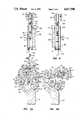
- FIG. 5is a posterior elevational view of a longitudinally central portion of the brace, taken along elevation line 5--5 of FIG. 2B, and illustrates a unique criss-crossed restraining strap structure which functions to inhibit extension of the leg past the extension limit angle setting of the brace;
- FIG. 6is a perspective view of one of the two adjustable hinge mechanisms used to pivotally interconnect the two thigh and calf support member sets on opposite lateral sides of the leg, portions of the interconnected support members being illustrated in phantom;
- FIG. 7is a left side elevational view of the hinge mechanism
- FIG. 8is a right side elevational view of the hinge mechanism
- FIGS. 9A and 9Bare cross-sectional views through the hinge assembly, taken along line 9--9 of FIG. 7, and respectively illustrate the interconnected support members at their extension and flexion angle limits;
- FIG. 10is an exploded perspective view of the hinge assembly
- FIGS. 11-13are front elevational views of the hinge mechanism sequentially illustrating certain adjustment steps used to selectively alter the position of one of its internal pivot stop members.
- FIGS. 11A--13Aare cross-sectional views through the hinge assembly, similar to FIG. 9A and 9B, and sequentially illustrate the position of the pivot stop member during each of the adjustment steps depicted in FIGS. 11-13.
- the present inventionprovides an improved motion restraining leg brace 10 which is connectable to a human leg 12 having a thigh portion 14, a calf portion 16, and a knee 18, and is operative to limit the pivotal extension and flexion motion of the leg about the knee.
- Brace 10includes a pair of elongated, rigid thigh support members 20 positionable to extend longitudinally along opposite lateral sides of the thigh portion 14, and a pair of elongated, rigid calf support members 22 positionable to extend longitudinally along opposite lateral sides of the calf portion 16.
- Thigh and calf support members 20, 22are preferably of a flat metal plate construction. They could, however, be alternately formed from another suitably rigid material having a different cross-section if desired.
- each of the hinge mechanisms 24may be rapidly and easily adjusted to selectively limit the relative pivotal motion between the support members 20, 22 in each set thereof (and thus the pivotal motion of the leg 12) to a predetermined angular range extending between a selectively variable flexion limit angle (FIG. 2A) and a selectively variable extension limit angle (FIG. 2B).
- FIGS. 2Aselectively variable flexion limit angle
- FIG. 2Bselectively variable extension limit angle
- Each of the thigh support members 20is defined by overlapping outer and inner longitudinal sections 20 a and 20 b which are interconnected in a unique manner that provides for the rapid and easy length adjustment of each of the thigh support members 20 to accommodate legs of varying lengths.
- each of the calf support members 22is defined by a pair of overlapping outer and inner longitudinal sections 22 a and 22 b which are adjustably interlocked in the same manner as the longitudinal sections which define each of the thigh support members.
- FIG. 3depicts in exploded fashion overlapping end portions of the sections 20 a and 20 b of one of the thigh support members 20.
- the adjustable interlocking structure provided on the sections 20 a and 20 bis identical to that provided on the overlapping sections 22 a and 22 b of each of the calf support members 22.
- the outer longitudinal section 20 a in FIG. 3has formed therethrough a longitudinally spaced series of laterally extending circular openings 26.
- the openings 26are equally spaced along the section 20 a , and each adjacent pair of such openings is adapted to laterally receive a longitudinally spaced pair of cylindrical, lateral projections 28 secured to the inner support member section 20 b adjacent its outer end.
- the overall length of the illustrated thigh support member 20may thus be rapidly and very easily adjusted simply by laterally inserting the projections 28 in different adjacent pairs of the openings 26 to vary the longitudinal overlap between the sections 20 a and 20 b .
- a retaining member in the form of a generally U-shaped clip 32is provided, the clip having a base wall 34 and a pair of transversely projecting side walls 36.
- Clip 32has a support arm portion 38 which is pivotally secured at its outer end to the underside of the section 20 b by means of a screw 40 extending downwardly through section 20 b .
- Screw 40is positioned longitudinally inwardly of the projections 28 and is spaced from the nearest projection a distance equal to the longitudinal space between the two projections.
- the retaining clip 32may be pivoted relative to the section 20 b (as indicated by the double ended arrow 42 in FIG. 3) between a first position (FIG. 3) in which the clip is swung outwardly to one side of the section 20 b , and a second position (FIG. 1) in which the clip is swung into frictional engagement with the sections 20 a and 20 b , with the clip side walls 36 respectively engaging upper and lower side surfaces of the overlapping portions of the interlocked sections 20 a and 20 b , over the projections 28, to prevent the lateral separation of the interlocked sections.
- the inner end of the support member section 20 ais provided with a generally semicircular notch 44 which, with the thigh support member 20 adjusted to its longest length (as in FIGS. 2A and 2B), receives the upwardly projecting head of the screw 40.
- the member 20is adjusted to a shorter length (as in FIG. 1), the projecting head of the screw 40 is received in one of the openings 26 to provide a further interlock stability between the sections 20 a and 20 b .
- this interlocking structurepermits the lengths of the thigh support members 20 to be very rapidly and securely adjusted. All that is necessary to change the overall length of either of the thigh support members is to pivot the retaining clip 32 outwardly, laterally separate the interlocked sections 20 a and 20 b , insert the projections 28 into a different adjacent pair of the openings 26, and then pivot the retaining clip 32 back into locking engagement with the interlocked sections 20 a and 20 b .
- each of the calf support members 22is provided with adjustably interlocking structure identical to that just described in conjunction with the thigh support members 20. Specifically, each of the calf support member sections 22 b is provided with the lateral projections 28, each of the outer support member sections 22 a has formed therethrough the longitudinally spaced series of openings 26, and a clip member 32 is pivotally secured to each of the sections 22 b as previously described in conjunction with the thigh support members 20.
- the thigh and calf support members 20, 22are operatively secured to the leg 18 by means of four connecting straps 46, 48, 50 and 52, each of which is secured to the brace 10 and adapted to transversely extend at least partially around the leg 18 and be tightened to hold the support members 20, 22 in place along the leg.
- foam padding elements 54(illustrated in phantom in FIG. 1 but omitted in FIGS. 2A and 2B) are secured to the brace and wrapped around the leg beneath each of these straps to add to the wearing comfort of the brace.
- Padding elements 54are conveniently held in place by hook fabric sections 55 a secured to contoured cradle elements 55 connected to the support members 20, 22 as indicated in FIGS. 1, 2A and 2B.
- Strap 46is positioned adjacent the outer ends 56 of the thigh support members 20
- strap 48is positioned centrally along the thigh support members 20
- strap 50is positioned centrally along the calf support members 22
- strap 52is positioned adjacent the outer ends 58 of the calf support members 22.
- Straps 48 and 50are of conventional construction and operation, and are respectively adapted to be looped around longitudinally central anterior areas of the thigh and calf portions 14, 16 of the leg 12 and be suitably buckled and tightened against these anterior thigh and calf portions to hold the support members 20, 22 in place along the leg.
- the straps 46 and 52are uniquely operative to significantly facilitate and maintain tee initial anterior posterior alignment of the thigh and calf support members 20 and 22 relative to the leg 12.
- the unique operation of the straps 46 and 52which are of identical construction and operation, is illustrated in FIG. 4 (see FIG. 1 also) which perspectively depicts outer end portions of the calf support member sections 22 a to which the strap 52 is connected.
- a central longitudinal portion of the strap 52is anchored to one of the support member sections 22 a , adjacent its outer end 58, and to one of the cradles 55, by means of rivets 60 or other suitable anchoring members.
- Outer end portions 62 and 64 of the free strap sections 66 and 68 of the strap 52are slidably looped through a pair of slotted connector members 70 and 72 secured to the support cradle 55 of the other support member sections 22 a adjacent its outer end 58, and then are secured to the strap sections 66 and 68 (as can be best seen in FIG. 1) by means of cooperating hook and pile surfaces 74 and 76 suitably affixed to the strap end portions 62, 64 and their associated strap sections 66 and 68.
- the strap sections 66 and 68thus respectively define independently adjustable anterior and posterior sections of the strap 52 which may be selectively and independently tightened or loosened to alter the anterior-posterior orientation of the support member sections 22 a on the calf portion 16 of the leg 18.
- the articulated side portions of the braceare positioned on the opposite lateral sides of the leg with the locking hinge mechanisms 24 (which have been previously set to their desired pivot stop settings as subsequently described) located on opposite sides of the knee 18 and appropriately aligned therewith.
- One of the free strap sections 66, 68 of the connecting strap 52may then be looped through its associated slotted connector member and suitably secured to itself and tightened against the calf portion 16 to precisely align the calf support member sections 22 a in a desired anterior-posterior relationship therewith.
- the anterior strap section 66may be looped through its connector member 70 and then secured and tightened to itself to prevent posteriorly directed movement of the support member sections 22 a .
- anterior-posterior alignment proceduremay then be carried out on the thigh support members 20 by adjustably tightening the independently adjustable anterior and posterior sections 66, 68 of the strap 46 which is identical in configuration and operation to the strap 52 just described.
- the anterior section 66 of strap 46may be suitably connected to a flexible plastic cradle member 78, as illustrated, to provide additional support along an upper thigh portion.
- the conventional anterior connecting straps 48 and 50may be extended around their associated anterior thigh and calf portions of the leg and suitably tightened to complete the connection of the brace 10 to the leg 12.
- the straps 46 and 52significantly facilitate the attachment of the brace 10 to the leg 12 and more effectively maintain the thigh and calf support members 20, 22 in precise anterior-posterior alignment therewith. It was heretofore necessary in conventional knee brace apparatus to manually hold the thigh and calf support members against the leg while wrapping a conventional connecting strap entirely around the leg and then securing the strap to itself. This was a somewhat awkward task which often resulted in undesirable misalignment between the brace support members and the leg to which they were connected. Additionally, essentially the same degree of awkwardness and difficulty was typically associated with altering the anterior-posterior alignment of the support members if it became necessary to change such alignment. However, with the straps 46 and 52, this anterior-posterior alignment may be very rapidly and easily changed simply by loosening one of the separate strap sections 66, 68 and tightening the other strap section.
- the adjustable hinge mechanisms 24may be set, in a manner subsequently described, to limit the pivotal motion of the interconnected sets of thigh and calf support members 20, 22 to a predetermined angular range extending between a leg flexion limit angle and a leg extension limit angle.
- the hinge mechanisms 24have been illustrated in FIGS. 2A and FIGS. 2B as being set to maintain a flexion limit angle of 90° (FIG. 2A) and an extension limit angle of 30° (FIG. 2B).
- various conventional motion restraining knee braceshave been provided with a pair of posterior restraining straps which are adapted to transversely extend along posterior portions of the leg above and below the knee joint and which may be tightened against the rear surface of the leg. While this proposed solution to the leg overextension problem reduces patient discomfort, it also is considerably less efficient in preventing overextension of the leg. This is due to the fact that the dual transverse strap restraint system used in various conventional braces moves the extension-inhibiting force areas away from the most effective point-namely, directly behind the knee.
- neither the single transverse posterior strap positioned directly behind the knee, or the two transversely extending posterior straps positioned above and below the knee, in any mannercompensate for the progressive extension strength of the human leg as it approaches its fully extended position.
- each of the strapsmust be tightened against the leg to be at all effective in inhibiting overextension of the leg.
- potential extension forceautomatically increases as previously mentioned. Accordingly, the closer the leg is moved toward its fully extended position, the more transverse restraining force is required to prevent the leg, via soft tissue "give", from being overextended. This interplay between the leg's angular position and its available extension force is simply not compensated for by conventional restraining strap structures.
- the present inventionprovides a uniquely constructed and operative restraining strap network 80 (FIGS. 2A, 2B and 5) which is significantly more effective and appreciably more comfortable than previous extension-inhibiting leg strap structures.
- Strap network 80includes a pair of restraining straps 82 and 84 which are carried on the support members 20, 22 by means of four slotted connector members 86, 88, 90 and 92 which are secured to the support members 20, 22 and positioned posteriorily thereof.
- Connectors 86, 88are respectively secured to the support member sections 20 b , 22 b of one of the pivotally interconnected sets of thigh and calf support members on opposite sides of its hinge mechanism 24, while the connectors 90, 92 are respectively secured to the support member sections 20 b and 22 b of the other set of pivotally connected thigh and calf support members on opposite sides of its hinge mechanism 24.
- the strap 82is looped through the connectors 88 and 90 so that a central portion 94 of the strap 82 extends diagonally between the connectors 88 and 90.
- the strap 84is looped through the connectors 86 and 92 so that a central portion 96 of the strap 84 extends diagonally between the connectors 86 and 92.
- the adjacent free ends of the straps 82, 84are connected to one another by adjustable buckle means 98 and 100 to define opposite end portions 102, 104 of the strap network 80, the network having a central portion defined by the criss-crossed central strap portions 94, 96.
- the generally hourglass-shaped restraining strap network 80is carried by the support members 20, 22 entirely posteriorily of the leg 12 and is positioned along a longitudinal posterior portion of the leg extending from longitudinally above the knee to longitudinally below the knee.
- the end portions 102, 104 of the network 80extend transversely around posterior halves of the leg 12, and the central strap portions 94, 96 cross at a point 106 positioned directly behind the knee 18.
- FIGS. 2A and 2Ait can also be seen that as the leg 12 is moved toward its extension limit position, the connector pairs 86, 90 and 88, 92 are moved further apart as the angle between the thigh support members 20 and the calf support members 22 is increased. This increase in the distance between such connector member pairs increasingly tightens the strap network 80 against the back of the leg as the leg approaches its extension limit position.
- the restraining straps 82, 84are slidably looped through the connector members 86, 88, 90 and 92 as previously described, this tightening of the strap network 80 equally tightens each of the separate segments 94, 96, 102 and 104 of the network 80 against the leg to apply thereagainst a progressively increasing, anteriorily directed force which inhibits extension of the leg beyond the extension limit angle setting of the hinge mechanisms 24.
- the uniquely configured strap network 80together with its slidable looped connection to the brace support members, maintains each portion of the strap network 80 in essentially equal tension as the network is gradually tightened against the back of the leg.
- each segment of the restraining strap networkis maintained in equal tension with all the other segments and is progressively loosened against the back of the leg until the leg reaches its flexion limit angle.
- the extension limiting restraining force of the strap network 80closely tracks the available extension strength of the leg 12, the restraining force being maximized at the extension limit of the leg and being minimized at the flexion limit thereof. While both the transverse end portions 102, 104 and the criss-crossed central portions 94, 96 of the network 80 are progressively tightened against the leg across a posterior longitudinal portion thereof extending above and below the knee, the central portions cannot be pinched between adjacent thigh and calf portions of the leg as the leg is being flexed. This, of course, eliminates the previous discomfort present in restraining structures which use a single posterior strap extending transversely around the leg directly behind the knee.
- the end sections 102, 104 of the networkalso provide a considerable improvement over conventional dual transverse restraining strap structure providing only a single level of tightness against the leg.
- Such end portionsare automatically loosened or tightened as the leg is flexed or extended so that the extension restraining force of the network exerts a maximum extension-inhibiting force when such maximum force is needed, and comfortably lessens the force as the leg is pivoted away from its crucial extension limit.
- Either of the buckle means 98, 100 on the network end portions 102, 104may be loosened or tightened to adjustably vary the tension of the network 80 with the leg in a fixed pivotal position.
- each of the adjustable locking hinge mechanisms 24, which pivotally interconnects one of the thigh support member inner sections 20 b to its associated calf support member inner sections 22 bincludes a pair of outer and inner metal base plates 110 and 112 which are identically configured.
- Each of the base plates 110, 112has a generally circular body portion 114 from which a generally rectangular connecting tab portion 116 tangentially extends.
- Formed through the body portions 114are an aligned pair of arcuate extension slots 118 which are positioned adjacent the peripheries of the body portions.
- Circumferentially spaced from the aligned slots 118are an aligned pair of arcuate flexion slots 120 which are also positioned adjacent the peripheries of the circular body portions 114. Slots 118 have circumferentially unobstructed radially outer portions 122, while the slots 120 have similarly unobstructed radially outer portions 124.
- each slot 118is provided with seven radially inwardly extending notches 126, each of such notches being circumferentially spaced from its immediately adjacent notch or notches by an angle of 15°.
- the uppermost notches 126 in the plates 110, 112correspond to an extension limit angle of 0° (at which the leg is fully straightened), with each clockwise successive notch 126 adding 15° to such extension limit angle so that the lowermost notches 126 in the plates 110, 112 in FIG. 10 correspond to an extension limit angle of 90°.
- each of the radially inner sides of the aligned flexion slots 120has formed therein ten radially inwardly extending notches 128 circumferentially spaced apart from one another by an angle of 15°.
- the circumferentially uppermost notches 128 in the plates 110, 112 in FIG. 10correspond in a manner subsequently described to a flexion angle of 135°, with each counterclockwise successive notch 128 reducing such flexion limit angle by 15° so that the notches 128 at the right ends of the slots 120 correspond to a flexion limit angle of 0°.
- An inner end portion of one of the thigh support member sections 20 bis sandwiched between and anchored to the connecting tabs 116 by means of three rivets 130 which are extended through aligned openings 132 (FIG. 10) formed through the tabs 116 and the support member section 20 b .
- An inner end portion 134 of one of the calf support member sections 22 bis also sandwiched between the body portions 114 of the base plates 110, 112. End portion 134 has formed therethrough a circular opening 136 which is aligned with somewhat smaller central circular openings 138 formed through the base plate body portions 114.
- the inner end portion 134 of the support member section 22 bis also provided along its right edge (as viewed in FIG.
- a lateral projection 140having formed thereon a concave, arcuately shaped extension stop surface 142.
- a concave, arcuately shaped flexion stop surface 144is Formed along the opposite edge of the support member section 22 b.
- the illustrated hinge mechanism 24is also provided with an adjustment member in the form of a circular dial element 146 having a base wall 148 from which an annular peripheral flange 150 axially projects.
- Base wall 148has a cylindrical, central depression 152 formed therein which projects axially in the same direction as the flange 150.
- Depression 152has an inner end wall 154 having a central opening 156 formed therethrough.
- a pair of cylindrical posts 158Also projecting in the same direction from the base wall 148 are a pair of cylindrical posts 158.
- Formed through the base wall 148 adjacent the radially inner surface 160 of flange 150are a circumferentially spaced series of circular observation holes 162, each of the holes 162 being spaced apart by 15° from its immediately adjacent hole or holes.
- a generally V-shaped spring member 172is carried within the body of the dial 146 and has a pair of leg portions 174 which are wrapped around the posts 158 (see FIGS. 9A and 9B) with the apex portion 176 of spring 172 being aligned with the dial flange internal depression 168.
- the dial 146is rotatably mounted, flange side down, on the outer side surface of the base plate 110 by means of a rivet 178 that extends sequentially through a washer 180, the central dial opening 156, the central opening 138 in the base plate 110, an annular bushing 182 rotatably received in the support member opening 136, the central opening 138 in the base plate 112, and a central opening 184 in a plastic support disc 186 positioned below the base plate 112 as viewed in FIG. 10.
- the disc 186On its outer side surface 188, the disc 186 has secured thereto a strip of hook fabric 190 (FIG. 1) which is attachable to a foam padding disc (not illustrated) that is positionable against one side of the knee.
- the head 192 of the rivet 178is recessed within the depression 152 formed in the base wall 148 of the dial 146.
- a thin plastic trim disc 194may be suitably adhered to the dial base wall 148 to cover the open end of the cylindrical recess 152.
- the rivet 178which interconnects the hinge elements 146, 110, 112 and 186 also mounts the support member section 22 b to the hinge for pivotal motion in clockwise and counterclockwise directions relative to the support member section 20 b .
- a pair of pivot stop members in the form of an extension limit disc 196 and a flexion limit disc 198are utilized.
- Discs 196 and 198are sandwiched between the base plates 110 and 112, and are respectively provided with central locking pin portions 200 and 202 which project axially outwardly from the opposite side surfaces of their associated limit disc.
- the opposite ends of the locking pin 200are received in circumferentially aligned pairs of the extension slot notches 126 in the base plates 110 and 112, and opposite ends of the locking pin 202 are received in circumferentially aligned flexion slot notches 128 in the base plates 110, 112.
- Upper end portions of the locking pins 200, 202project upwardly from the upper side surface of base plate 110 and are engaged by the radially inner surface 160 of the dial flange 150 to thereby captively retain these locking pins in their respective slot notch pairs.
- the pins 200, 202are prevented from moving circumferentially around their associated slots 118, 120 to thereby lock the discs 196, 198 in their relative circumferential orientation with respect to the base plates 110, 112 as representatively illustrated in FIG. 9A.
- the locked disc 196functions to limit the angular extension between the support member sections 20 b and 22 b by engaging the stop surface 142 on the support member section 22 b (FIG. 9A), while the disc 198 functions to limit the flexion motion between the support member sections 20 b and 22 b when the stop surface 144 of support member section 22 b is brought into engagement with the locked disc 198 (FIG. 9B).
- the locked discs 196, 198thus function to limit the relative pivotal motion of the support member sections 20 b , 22 b to a predetermined angular range extending from a representative extension limit angle of 30° (FIG. 9A) and a representative flexion limit angle of 90° (FIG. 9B).
- the relative angular orientations of the locking pins 200, 202 in their associated pairs of slots 118 and 120, and thus the relative positions of the pivot stop discs 196 and 198,are visually ascertainable simply by looking into the observation holes 162 formed in the base wall 148 of the hinge dial 146. As illustrated in FIG. 6, the pins 200, 202 are readily visible through a pair of these observations holes 162 which are aligned with the pins, regardless of their relative orientation, when the dial 146 is in its locked position as subsequently described.
- the visually determinable location of the pins 200, 202may be easily correlated with extension and flexion angle indicia markings 204 and 206 suitably imprinted on the outer side surface of the base plate 110 around the periphery of its circular body portion. By observing which of these angle markings the particular locking pin is aligned with, both the flexion and extension limit settings of the hinge may be rapidly ascertained simply by looking at the dial.
- the locking pins 200 and 202are captively retained at their opposite ends within circumferentially aligned pairs of slot notches 126 and 128 on the laterally spaced base plates 110 and 112 by the inner surface 160 of the dial flange 150 to thereby circumferentially lock the extension and flexion pivot stop discs 196 and 198 relative to the base plates.
- the dial 146is rotated to its lockable position illustrated in FIG. 6, with the triangular dial tabs 164 and 165 facing generally upwardly as viewed in FIG. 6.
- the dial 146may be rapidly and securely locked in this position by the physician or physical therapist who initially adjusts the hinge mechanism to prevent (or at least significantly hinder) subsequent rotation of the dial 146, and undesirable readjustment of the pin settings, by the patient upon whose leg the brace is operatively secured.
- dial locking disc 208(FIG. 10) which is essentially identical in size and configuration to the pivot stop discs 196 and 198.
- the dial locking disc 208is provided with a central, axially projecting locking pin 210 which is slidably received at its opposite ends in a pair of generally radially extending slots 212 formed through the base plates 110, 112 adjacent the junctures of their circular body portions 114 and connecting tabs 116.
- the dial locking disc 208is sandwiched between the base plates 110 and 112.
- the pin 210is biased toward the radially inner ends 214 of the slots 212 (FIG. 10) by means of a small spring element 216 carried between the plates 110 and 112.
- Spring element 216has a coiled central portion 218 which receives a small pin 220 carried at its opposite ends in a pair of small circular openings 222 (only one of which is visible in FIG. 10) formed through the connecting tabs 116 of the base plates 110, 112.
- Extending transversely in the same direction from opposite ends of the coiled central spring portion 218are a pair of spring arms 224, 226 which, as best illustrated in FIG. 9A and 9B, respectively bear against the inner end 228 of the support member section 20 b and the dial locking disc 208.
- the force of spring arm 226 on the disc 208resilient urges the locking pin 210 inwardly along the slots 212 and biases the pin 210 toward its illustrated position at the inner ends of such slots 212.
- the outer side surface of one of the triangular dial tabs 164, 165engages a portion of the pin 210 which projects outwardly through the slot 212 in the outer base plate 110 and, as the dial is rotated further toward its lockable position, urges the pin 210 outwardly along its retaining slots 212 against the biasing force of the spring element 216.
- the spring 216forces such outwardly projecting pin portion inwardly into the exterior dial notch 168 so that with the dial in the position illustrated in FIG. 6 and the outwardly projecting portion of pin 210 rests in the bottom of the dial notch 168.
- the dial 146may be locked to prevent patient tampering with the hinge setting.
- This locking of the dialis accomplished by threading a plastic locking tie member 230 (FIG. 6) through a pair of small circular openings 232 formed through the base plates 110, 112 adjacent the pin slots 212, and then locking the tie to itself by inserting an end portion 234 of the tie through a ratcheted buckle portion 236 thereof. Once the end portion 234 is inserted through the buckle 236, it cannot be pulled outwardly therethrough, and the tie 230 must be cut to remove it from the openings 232.
- the portion of the plastic locking tie 230 which extends through the openings 232is positioned radially outwardly of and closely adjacent the periphery of the dial locking disc 208. Accordingly, such portion of the locking tie prevents appreciable radially outward movement of the dial locking disc 208 parallel to the slots 212. In turn, this prevents the locking pin 210 from moving outwardly along its retaining slots 212. Held in the position illustrated in FIGS. 6, 9A and 9B by the locking tie 230, the outwardly projecting portion of the pin 210 thus prevents rotation of the dial 146 in either direction. For example, if an attempt is made to turn the dial in either direction, the interengagement between the now fixed outwardly projecting portion of the pin 210 and one of the inner side surfaces of the triangular dial tabs 164, 165 prevent rotation of the dial.
- the locking tie 230is first cut and removed from its openings 232 to permit rotation of the dial 146.
- Dial 146as viewed in FIGS. 6 and 11-13, is then rotated in a clockwise direction away from its previously locked position until the exterior dial notch 166 is brought into alignment with the locking pin 200 of the extension pivot stop disc 196 (FIGS. 11 and 11A).
- the apex 176 of the spring 172engages the locking pin 200 and resilient urges it radially outwardly from its initial pair of slot notches 126 and into the depression 168 formed in the inner surface of the dial flange 150.
- This radially outward movement of the locking pin 200carries it into the circumferentially unobstructed radially outer portions 122 of the extension slots 118.
- Such radially outward movement of the pin 200also causes the pivot stop disc 196 to pop outwardly beyond the peripheries of the base plates 110, 112 as illustrated in FIGS. 11 and 11A.
- the disc 196is both visible and manually accessible by the physician or technician performing the hinge adjustment.
- the locking pin 200 in the position thereof illustrated in FIGS. 11 and 11Ais captively retained in the dial surface depression 168 by the apex 176 of the spring element 172. Accordingly, the captively retained pin 200 is now held by the dial 146 for rotational movement therewith so that the pin 200 may be moved around the unobstructed radial portion 122 of the extension slot 118.
- the dial 146is rotated 15° in a clockwise direction (as viewed in FIG. 12) to move the pin 200 along its slots 118 to bring it into circumferential alignment with a new pair of notches 126 a (FIG. 12A) which correspond to an extension limit angle of 45°.
- This clockwise circumferential movement of the pin 200 in FIG. 12appears as a counterclockwise movement of such pin in FIG. 12A.
- the repositioned pivot stop disc 196is then manually pushed radially inwardly between the base plates 110, 112, as indicated by the arrows 238 in FIGS. 12 and 12A, to force the locking pin 200, against the biasing force of the spring element 172, into the aligned pair of slot notches 126 a .
- the disc 196is then manually held in this position while the dial 146 is rotated in a counterclockwise direction (FIG. 13) toward its lockable position (FIG. 6) to thereby disengage the spring apex 176 from the pin 200 and move the inner surface 160 of the dial flange 150 into engagement with the pin 200 to thus captively retain the pin in its new pair of slot notches 126 a .
- the dial 146may then be further rotated in a counterclockwise direction until it reaches its lockable position in which the pin 210 is received in the exterior dial notch 166.
- a new locking tiemay then be threaded through the base plate openings 232 to again rotationally lock the dial as previously described.
- the hinge mechanism 24 in its readjusted positionhas a flexion limit angle of 90° and an extension limit angle of 45°.
- the circumferential position of the flexion locking pin 202may also be altered, before or after the adjustment of the extension locking pin 200 in a manner similar to that just described, before a new locking tie is utilized to rotationally lock the dial.
- each of the hinge mechanisms 24 of the present inventionmay be rapidly and very easily adjusted to alter either or both of the extension and flexion angle limits thereof.
- the locking pins 200, 202provide very secure shear locks between the discs 196, 198 and the base plates 110, 112 to firmly prevent the pivotally interconnected thigh and calf support members 20, 22 from moving beyond the angular stop settings of their associated hinge.
- the hinge mechanisms 24have several movable parts, such parts are captively retained between the base plate portions of the hinge so that they cannot become dislodged or lost during or after adjustment of the hinge.
- the unique operation of the dial locking disc 208permits the hinge mechanisms to be easily rendered essentially tamper proof, but may be easily prepared for professional adjustment simply by cutting and removing the plastic locking tie.
- the actual setting of each of the hinge mechanismsis readily visible simply by viewing the positions of the locking pins 200, 202 through the observation holes 162 formed in the dial.
- a circumferentially spaced series of small finger depressions 240are formed around the periphery thereof.
- these improved hinge mechanisms 24afford the brace 10 with an advantageous variety of significant structural and operational improvements over previously utilized motion restraining knee braces of this general type.
Landscapes
- Health & Medical Sciences (AREA)
- Nursing (AREA)
- Orthopedic Medicine & Surgery (AREA)
- Engineering & Computer Science (AREA)
- Biomedical Technology (AREA)
- Heart & Thoracic Surgery (AREA)
- Vascular Medicine (AREA)
- Life Sciences & Earth Sciences (AREA)
- Animal Behavior & Ethology (AREA)
- General Health & Medical Sciences (AREA)
- Public Health (AREA)
- Veterinary Medicine (AREA)
- Orthopedics, Nursing, And Contraception (AREA)
- Prostheses (AREA)
Abstract
Description
Claims (38)
Priority Applications (1)
| Application Number | Priority Date | Filing Date | Title |
|---|---|---|---|
| US07/068,931US4817588A (en) | 1987-07-01 | 1987-07-01 | Motion restraining knee brace |
Applications Claiming Priority (1)
| Application Number | Priority Date | Filing Date | Title |
|---|---|---|---|
| US07/068,931US4817588A (en) | 1987-07-01 | 1987-07-01 | Motion restraining knee brace |
Publications (1)
| Publication Number | Publication Date |
|---|---|
| US4817588Atrue US4817588A (en) | 1989-04-04 |
Family
ID=22085630
Family Applications (1)
| Application Number | Title | Priority Date | Filing Date |
|---|---|---|---|
| US07/068,931Expired - LifetimeUS4817588A (en) | 1987-07-01 | 1987-07-01 | Motion restraining knee brace |
Country Status (1)
| Country | Link |
|---|---|
| US (1) | US4817588A (en) |
Cited By (139)
| Publication number | Priority date | Publication date | Assignee | Title |
|---|---|---|---|---|
| US4955369A (en)* | 1988-10-27 | 1990-09-11 | Bledsoe Gary R | Dynamically shiftable counter shear force knee brace |
| US4958643A (en)* | 1989-06-16 | 1990-09-25 | Timothy Pansiera | Hinge joint |
| US4969452A (en)* | 1989-03-24 | 1990-11-13 | Petrofsky Research, Inc. | Orthosis for assistance in walking |
| EP0401170A1 (en)* | 1989-05-30 | 1990-12-05 | Marc Vanden Broeck | Joint mechanism for pair of orthotic supports |
| US4982732A (en)* | 1990-02-06 | 1991-01-08 | Orthopedic Technology, Inc. | Orthopedic rehabilitation knee brace |
| US5000170A (en)* | 1988-02-02 | 1991-03-19 | Protectair Limited | Adjustable bipivotal hinge with interdigitating abutment plates |
| US5031606A (en)* | 1991-01-17 | 1991-07-16 | Randolph Austin Company | Brace and hinge apparatus and method |
| US5036837A (en)* | 1990-02-09 | 1991-08-06 | Bio-Tec, Inc. | Dynamic extension splint |
| US5052379A (en)* | 1989-04-27 | 1991-10-01 | Soma Dynamics Corporation | Combination brace and wearable exercise apparatus for body joints |
| US5058574A (en)* | 1990-06-22 | 1991-10-22 | Anderson Lucinda L | Therapeutic limb brace |
| US5060640A (en)* | 1990-03-14 | 1991-10-29 | Becker Orthopedic Appliance Company | Knee brace |
| US5119805A (en)* | 1986-06-20 | 1992-06-09 | Cadoret Alain J B | Orthopedic apparatus for instable knees |
| WO1993002644A1 (en)* | 1991-08-05 | 1993-02-18 | Ultraflex Systems, Inc. | Dynamic splint |
| US5188584A (en)* | 1989-03-24 | 1993-02-23 | Petrofsky Research, Inc. | Orthosis for assistance in walking |
| US5356370A (en)* | 1993-09-09 | 1994-10-18 | Generation Ii Orthotics Inc. | Antifriction mechanical joint for an orthopedic knee brace |
| US5358468A (en)* | 1993-03-26 | 1994-10-25 | Matthew C. Longo | Adjustable resistance knee rehabilitating and strengthening apparatus |
| US5399154A (en)* | 1993-06-30 | 1995-03-21 | Empi, Inc. | Constant torque range-of-motion splint |
| US5400806A (en)* | 1993-01-04 | 1995-03-28 | Generation Ii Orthotics, Inc. | Post operative knee brace and method for its use |
| US5437611A (en)* | 1993-12-01 | 1995-08-01 | Orthotic Rehabilitation Products, Inc. | Dynamic brace joint |
| US5437619A (en)* | 1993-06-30 | 1995-08-01 | Empi, Inc. | Range-of-motion splint with eccentric spring |
| US5472410A (en)* | 1994-04-22 | 1995-12-05 | Deroyal/Lmb, Inc. | Adjustable flexion and extension joint orthoses |
| US5520627A (en)* | 1993-06-30 | 1996-05-28 | Empi, Inc. | Range-of-motion ankle splint |
| US5571078A (en)* | 1993-06-30 | 1996-11-05 | Empi, Inc. | Range-of-motion ankle splint |
| US5571206A (en)* | 1994-05-16 | 1996-11-05 | Restorative Care Of America Incorporated | Leg amputee orthosis |
| FR2733905A1 (en)* | 1995-05-12 | 1996-11-15 | Berrehail Mohammed | Hinged brace for knee |
| US5630791A (en)* | 1995-04-03 | 1997-05-20 | Glynn Orthopedics Services, Inc. | Orthotic joint |
| US5658241A (en)* | 1990-02-09 | 1997-08-19 | Ultraflex Systems, Inc. | Multi-functional dynamic splint |
| US5672152A (en)* | 1995-11-28 | 1997-09-30 | Breg, Inc. | Hinge for an orthopedic brace having an adjustable range of rotation |
| US5749840A (en)* | 1989-12-07 | 1998-05-12 | Ultraflex Systems, Inc. | Dynamic splint |
| US5759165A (en)* | 1993-06-30 | 1998-06-02 | Empi, Inc. | Forearm supination range-of-motion orthosis |
| US5766140A (en)* | 1996-05-01 | 1998-06-16 | Smith & Nephew Donjoy, Inc. | Angular compensation device for a joint brace |
| US5814000A (en)* | 1996-07-12 | 1998-09-29 | Professional Products, Inc. | Adjustable joint brace |
| US5817040A (en)* | 1995-08-24 | 1998-10-06 | Restorative Care Of America Incorporated | Knee and elbow orthosis |
| US5827208A (en)* | 1995-11-28 | 1998-10-27 | Breg, Inc, | Hinge for an orthopedic brace having a selectively positionable stop to limit rotation |
| US5891068A (en)* | 1997-03-28 | 1999-04-06 | Kenney; John P. | Orthotic device for treating contractures due to immobility |
| WO1999020212A1 (en)* | 1997-10-22 | 1999-04-29 | Smith & Nephew, Inc. | Joint brace hinges |
| US5954621A (en)* | 1993-07-09 | 1999-09-21 | Kinetecs, Inc. | Exercise apparatus and technique |
| US5980435A (en)* | 1993-07-09 | 1999-11-09 | Kinetecs, Inc. | Methods of therapy or controlled exercise using a jointed brace |
| US5997493A (en)* | 1996-09-25 | 1999-12-07 | Johnson & Johnsonprofessional, Inc. | "Hinge with movement limitation" |
| US6064912A (en)* | 1997-03-28 | 2000-05-16 | Kenney; John P. | Orthotic/electrotherapy for treating contractures due to immobility |
| US6080122A (en)* | 1998-08-24 | 2000-06-27 | Gulledge; Ronald E. | Motion restraining brace |
| US6206846B1 (en)* | 1997-03-28 | 2001-03-27 | John P. Kenney | Orthotic device for treating contractures due to immobility |
| EP1086672A2 (en) | 1999-09-25 | 2001-03-28 | Depuy Orthopaedics, Inc. | Orthopaedic brace having a range of motion hinge with radially actuated stops |
| EP1086670A2 (en) | 1999-09-27 | 2001-03-28 | Depuy Orthopaedics, Inc. | Adjustable orthopaedic brace |
| EP1086671A2 (en) | 1999-09-27 | 2001-03-28 | Depuy Orthopaedics, Inc. | Orthopaedic brace having a range of motion hinge with an adjustable-length strut |
| EP1088534A2 (en) | 1999-09-28 | 2001-04-04 | Depuy Orthopaedics, Inc. | Range of motion orthopaedic joint brace with a linearly actuated stop |
| US6287268B1 (en)* | 1998-06-25 | 2001-09-11 | Bodyworks Properties Limited | Brace |
| US6368297B1 (en)* | 1997-04-01 | 2002-04-09 | Camp Scandinavia Ab | Hyperextension knee orthosis |
| US6383156B1 (en) | 1999-09-27 | 2002-05-07 | Dj Orthopedics, Llc | Orthopaedic brace having a range of motion hinge with an adjustable-length strut |
| US6524265B2 (en) | 2001-04-27 | 2003-02-25 | Theodore B. Hogg | Leg brace support structure |
| US6623439B2 (en) | 2001-08-31 | 2003-09-23 | Dj Orthopedics, Llc | Contoured knee brace frame |
| US20040049140A1 (en)* | 2002-09-11 | 2004-03-11 | Doty Alexis E. | Lockable Hinge |
| JP2004515312A (en)* | 2000-12-12 | 2004-05-27 | ディージェイ オーソペディクス,リミテッド ライアビリティー カンパニー | Orthopedic brace with adjustable length support |
| US6764457B2 (en) | 2001-04-27 | 2004-07-20 | Hogg Theodore B | Leg brace support structure |
| US20040153015A1 (en)* | 2003-01-30 | 2004-08-05 | Scott Seligman | Motion controlling hinge for orthopedic brace |
| US20040158184A1 (en)* | 2003-01-16 | 2004-08-12 | Davis Perry H. | Orthopedic splint |
| US20040267179A1 (en)* | 2003-06-30 | 2004-12-30 | Max Lerman | Knee unloading orthotic device and method |
| US20050070831A1 (en)* | 2003-09-29 | 2005-03-31 | Royce Medical Company | Adjustable ergonomic knee brace |
| WO2004060203A3 (en)* | 2002-12-30 | 2005-05-06 | Innovation Sports Inc | Hinge system for regulating knee joint flexion and extension |
| US20050148918A1 (en)* | 2004-01-06 | 2005-07-07 | Nathanson Jeremy J. | Orthopedic brace suspension system |
| US20050177082A1 (en)* | 2004-02-05 | 2005-08-11 | Bledsoe Gary R. | Muscle powered dynamic knee brace |
| EP1563812A1 (en) | 1999-09-27 | 2005-08-17 | DJ Orthopedics, LLC | Orthopaedic brace having a range of motion hinge with an adjustable-length strut |
| US20050187505A1 (en)* | 2004-02-24 | 2005-08-25 | Tamarack Habilitation Technologies, Inc. | Spherical joint orthosis |
| US7001349B2 (en) | 2003-08-12 | 2006-02-21 | Otto Bock Healthcare Gmbh | Orthopedic splint |
| US20060155230A1 (en)* | 2005-01-12 | 2006-07-13 | Mason Jeffrey T | Releasably locking hinge for an orthopedic brace having adjustable rotation limits |
| US20060155232A1 (en)* | 2005-01-12 | 2006-07-13 | Ceriani Dylann D | Method for fitting an orthopedic brace to the body |
| US20060155229A1 (en)* | 2005-01-12 | 2006-07-13 | Ceriani Dylann D | Support assembly for an orthopedic brace having a length-adjusting mechanism |
| US20060247565A1 (en)* | 2003-09-29 | 2006-11-02 | David Cormier | Adjustable ergonomic knee brace |
| US20060271112A1 (en)* | 2004-11-15 | 2006-11-30 | Martinson James B | Instrumented orthopedic and other medical implants |
| US20070067957A1 (en)* | 2005-09-23 | 2007-03-29 | Restorative Care Of America Incorporated | A rachet hinge for a knee or elbow orthosis |
| US20070073296A1 (en)* | 2005-09-13 | 2007-03-29 | Panchbhavi Vinod K | Surgical laser guide and method of use |
| US20070270976A1 (en)* | 2002-04-25 | 2007-11-22 | Ultraflex Systems, Inc. | Ambulating ankle & knee joints with bidirectional dampening and assistance using elastomeric restraint |
| US20080200856A1 (en)* | 2007-02-20 | 2008-08-21 | Gregory Cadichon | Method, apparatus, and system for bracing a knee |
| WO2007146320A3 (en)* | 2006-06-15 | 2008-09-12 | Danny Joe Mckeon | Controllable leg restraint |
| US20080306413A1 (en)* | 2004-06-15 | 2008-12-11 | Denis Crottet | Device for Measuring Tibio-Femoral Force Amplitudes and Force Locations in Total Knee Arthroplasty |
| US7544174B2 (en) | 2006-09-29 | 2009-06-09 | Djo, Llc | Quiet flexion/extension stop for orthopedic brace and orthopedic brace incorporating a quiet flexion/extension stop |
| US20090198162A1 (en)* | 2002-04-25 | 2009-08-06 | Ultraflex Sytems, Inc. | Ambulating knee joint |
| US20100049108A1 (en)* | 2008-08-25 | 2010-02-25 | Ebi, Llc | Adjustable hinge for orthopedic brace |
| US20100121160A1 (en)* | 1999-06-23 | 2010-05-13 | Izex Technologies, Inc. | Remote psychological evaluation |
| US20100174220A1 (en)* | 2009-01-08 | 2010-07-08 | Breg, Inc. | Orthopedic Elbow Brace Having a Length-Adjustable Support Assembly |
| US20100227741A1 (en)* | 2009-03-06 | 2010-09-09 | Leon Rosenberg | Apparatus for isolating an injured ankle or foot during aerobic exercise |
| US7811242B2 (en) | 2004-06-24 | 2010-10-12 | Djo, Llc | Motion controlling hinge for orthopedic brace |
| US20110009786A1 (en)* | 2009-07-13 | 2011-01-13 | Shu-Chen Chan | Limiting connector for knee brace |
| US20110071451A1 (en)* | 2008-06-03 | 2011-03-24 | Paulos Lonnie E | Hyperextension brace assembly and methods of use |
| US20120143111A1 (en)* | 2010-12-01 | 2012-06-07 | Medical Technology Inc. | Adjustable pad and orthopedic knee brace including same |
| US20130172797A1 (en)* | 2011-08-19 | 2013-07-04 | Chiron Designs Llc | Orthotic strapping system |
| USD693930S1 (en) | 2012-07-12 | 2013-11-19 | Ossur Hf | Pair of struts for an orthopedic device |
| US8678979B2 (en) | 1998-09-01 | 2014-03-25 | Izex Technologies, Inc. | Remote monitoring of a patient |
| US8690812B2 (en) | 2012-01-05 | 2014-04-08 | United Surgical Associates, Inc. | Post operative knee brace with uniform symmetrical lateral adjustment |
| US8784475B2 (en) | 2004-11-15 | 2014-07-22 | Izex Technologies, Inc. | Instrumented implantable stents, vascular grafts and other medical devices |
| US8808211B2 (en) | 2008-06-03 | 2014-08-19 | The Lonnie and Shannon Paulos Trust | Elastic brace assembly and methods of use |
| US20140234016A1 (en)* | 2013-02-21 | 2014-08-21 | Tecnoway Srl | Brace for articulation |
| JP2014526947A (en)* | 2011-09-16 | 2014-10-09 | タウンセンド デザイン | Knee support with tool-free length adjustment device |
| USD716000S1 (en) | 2012-08-14 | 2014-10-21 | Medical Technology Inc. | Sports leg protector |
| US9021614B2 (en) | 2011-02-18 | 2015-05-05 | Medical Techology, Inc. | Leg protector for sports activities |
| WO2015104437A1 (en)* | 2014-01-10 | 2015-07-16 | Juan Manuel Galbis Abascal | Equipment for teaching and improving sporting movements |
| US9125730B2 (en) | 2011-10-31 | 2015-09-08 | Ossur Hf | Orthopedic device for dynamically treating the knee |
| LU92396B1 (en)* | 2014-03-10 | 2015-09-11 | Zours Peter | Modulare Knieorthese |
| US9220624B2 (en) | 2010-09-16 | 2015-12-29 | Ossur Hf | Posterior cruciate ligament support brace |
| USD749227S1 (en)* | 2013-08-02 | 2016-02-09 | Cyberdyne Inc. | Main body of a wearable human-motion-support apparatus |
| CN105491979A (en)* | 2013-08-09 | 2016-04-13 | 罗云 | Knee joint orthosis having offloading function |
| US9320634B2 (en) | 2008-06-03 | 2016-04-26 | The Lonnie and Shannon Paulos Trust (as Amended and Restated) F/K/A The James Dizikis Trust Dated February 26, 2008 | Training brace assembly and methods of use |
| US9351864B2 (en) | 2013-01-25 | 2016-05-31 | Ossur Hf | Orthopedic device having a dynamic control system |
| US9539135B2 (en) | 2013-01-25 | 2017-01-10 | Ossur Hf | Orthopedic device having a dynamic control system and method for using the same |
| US9554934B2 (en) | 2008-06-03 | 2017-01-31 | The Lonnie and Shannon Paulos Trust | Elastic brace assembly and methods of use |
| US9597786B2 (en) | 2013-08-22 | 2017-03-21 | Ossur Hf | Torque limiting tool and method for using the same |
| WO2017053831A1 (en)* | 2015-09-25 | 2017-03-30 | Cain Frank J | Rehabilitation device for a damaged or surgically repaired knee |
| US9615955B2 (en) | 2011-04-21 | 2017-04-11 | Breg, Inc. | Orthopedic knee brace with dynamically changing medial and lateral hinges |
| US9615967B2 (en) | 2010-12-30 | 2017-04-11 | Coolsystems, Inc. | Reinforced therapeutic wrap and method |
| USD807516S1 (en)* | 2014-03-31 | 2018-01-09 | Park-Hannifin Corporation | Movement assistance device—thigh component |
| USD813089S1 (en) | 2016-11-08 | 2018-03-20 | Ossur Iceland Ehf | D-ring |
| US9925082B2 (en) | 2012-03-20 | 2018-03-27 | Ossur Hf | Orthopedic device |
| US9943437B2 (en) | 2009-10-22 | 2018-04-17 | Coolsystems, Inc. | Temperature and flow control methods in a thermal therapy device |
| US9980844B2 (en) | 2007-02-13 | 2018-05-29 | Coolsystems, Inc. | Flexible joint wrap |
| US20180193180A1 (en)* | 2017-01-06 | 2018-07-12 | Djo, Llc | Orthosis, related components and methods of use |
| KR20180098960A (en)* | 2017-02-27 | 2018-09-05 | 인하대학교 산학협력단 | Device for guiding human body joint motion |
| US10143581B2 (en) | 2013-06-21 | 2018-12-04 | Ossur Hf | Dynamic tension system for orthopedic device |
| USD835289S1 (en) | 2016-11-08 | 2018-12-04 | Ossur Iceland Ehf | Orthopedic device |
| CN109259921A (en)* | 2018-11-29 | 2019-01-25 | 厦门杰斯医疗器械有限公司 | A kind of adjustable joint protection brace with self-locking function |
| WO2019152639A1 (en)* | 2018-01-31 | 2019-08-08 | University Of Massachusetts | System and methods for a hip joint reduction procedure |
| US10413437B2 (en) | 2013-01-25 | 2019-09-17 | Ossur Iceland Ehf | Orthopedic device having a dynamic control system and method for using the same |
| US10427023B2 (en)* | 2016-04-15 | 2019-10-01 | Bsn Sports, Llc | Shoulder pads and method of manufacturing the same |
| US10456320B2 (en) | 2013-10-01 | 2019-10-29 | Coolsystems, Inc. | Hand and foot wraps |
| US10463565B2 (en) | 2011-06-17 | 2019-11-05 | Coolsystems, Inc. | Adjustable patient therapy device |
| US10512305B2 (en) | 2014-07-11 | 2019-12-24 | Ossur Hf | Tightening system with a tension control mechanism |
| US10524948B2 (en) | 2013-01-22 | 2020-01-07 | Orthocare Medical Equipment, Llc | Micro-adjustable telescoping arms for orthopedic braces |
| US10617549B2 (en) | 2016-04-04 | 2020-04-14 | Ossur Iceland Ehf | Orthopedic device |
| US10653546B2 (en) | 2014-10-31 | 2020-05-19 | Ossur Hf | Orthopedic device having a dynamic control system |
| US10675166B2 (en) | 2008-06-03 | 2020-06-09 | The Lonnie and Shannon Paulos Trust | Adjustable brace assembly and methods of use |
| US10859295B2 (en) | 2016-04-13 | 2020-12-08 | ZeoThermal Technologies, LLC | Cooling and heating platform |
| US11013635B2 (en) | 2004-05-17 | 2021-05-25 | Coolsystems, Inc. | Modular apparatus for therapy of an animate body |
| US11197553B2 (en)* | 2019-04-04 | 2021-12-14 | Hyundai Motor Company | Wearable chair |
| US11229296B2 (en)* | 2019-04-02 | 2022-01-25 | Hyundai Motor Company | Seating support device of wearable chair |
| US11547590B2 (en) | 2017-11-27 | 2023-01-10 | Ossur Iceland Ehf | Orthopedic device having a suspension element |
| US11633529B2 (en) | 2018-12-31 | 2023-04-25 | Nuwellis, Inc. | Blood filtration systems |
| US11672693B2 (en) | 2014-08-05 | 2023-06-13 | Avent, Inc. | Integrated multisectional heat exchanger |
| US11839564B1 (en) | 2019-08-08 | 2023-12-12 | Preferred Prescription, INC | Knee orthosis, adjustable |
| US11918500B1 (en) | 2020-03-31 | 2024-03-05 | Preferred Prescription, Inc. | Hinged knee brace with double upper strap arrangement |
| US12121463B1 (en) | 2020-02-13 | 2024-10-22 | Preferred Prescription, Inc. | Knee/elbow brace |
Citations (31)
| Publication number | Priority date | Publication date | Assignee | Title |
|---|---|---|---|---|
| DE170739C (en)* | ||||
| US21872A (en)* | 1858-10-26 | Extension-splint | ||
| US552143A (en)* | 1895-12-31 | Adjustable splint | ||
| GB110209A (en)* | 1916-10-20 | 1917-10-18 | Harold Edwin Cooper | Improvements in or relating to Orthoædic, Fracture, and like Surgical Appliances. |
| US2250493A (en)* | 1940-06-10 | 1941-07-29 | George M Milne | Foot and leg exercising device |
| US2558986A (en)* | 1947-09-20 | 1951-07-03 | Seelert Arthur | Leg brace |
| DE1024204B (en)* | 1953-12-19 | 1958-02-13 | Hans Feierabend | Orthopedic knee sleeves |
| US3785371A (en)* | 1972-07-26 | 1974-01-15 | Surgical Appliance Ind | Elbow sleeve |
| US3805773A (en)* | 1973-01-17 | 1974-04-23 | Ballert Orthopedic Corp | Training assist brace |
| GB1449554A (en)* | 1974-11-01 | 1976-09-15 | Konvalin R | Adjustable leg brace |
| US4057056A (en)* | 1976-06-01 | 1977-11-08 | Payton Hugh W | Walking cast |
| US4057853A (en)* | 1976-07-01 | 1977-11-15 | Mclane Larry A | Snake leggings |
| US4090508A (en)* | 1977-03-15 | 1978-05-23 | Medical Specialties, Incorporated | Orthopedic knee brace |
| US4240414A (en)* | 1979-08-09 | 1980-12-23 | Theisler Charles W | Knee brace |
| US4271831A (en)* | 1979-03-12 | 1981-06-09 | Deibert Daniel T | Knee brace |
| US4337764A (en)* | 1981-03-02 | 1982-07-06 | United States Manufacturing Company | Adjustable motion brace |
| US4340041A (en)* | 1979-01-24 | 1982-07-20 | Blanc Gmbh & Co. | Articulate splint for surgical purposes |
| US4381768A (en)* | 1981-05-18 | 1983-05-03 | Stainless Mfg., Inc. | Knee orthosis |
| US4463751A (en)* | 1982-12-27 | 1984-08-07 | Bledsoe Gary R | Stabilizing knee hinge |
| WO1985002536A1 (en)* | 1983-12-16 | 1985-06-20 | Anthony Leonard Peck | Lockable pivotal connection device |
| US4531731A (en)* | 1984-01-09 | 1985-07-30 | Unique Functional Products | Gymnastic equipment |
| US4554913A (en)* | 1983-11-07 | 1985-11-26 | Scott Orthopedics, Inc. | Adjustable joint for a knee brace |
| US4556053A (en)* | 1984-02-08 | 1985-12-03 | United States Manufacturing Company | Knee orthosis with leg stabilizing means |
| US4565190A (en)* | 1984-07-13 | 1986-01-21 | Northwestern University | Knee orthosis with swivel-action supracondular cuff |
| US4572170A (en)* | 1984-06-06 | 1986-02-25 | Cronk Richard V | Preventive knee brace |
| US4614181A (en)* | 1983-11-08 | 1986-09-30 | Rehband Anatomiska Ab | Hinge for knee joint bandage |
| US4620532A (en)* | 1983-09-26 | 1986-11-04 | Lenox Hill Brace Shop, Inc. | Adjustment device for an articulated joint brace |
| US4624247A (en)* | 1985-01-22 | 1986-11-25 | Medical Designs, Inc. | Leg brace for controlling subluxation |
| US4632098A (en)* | 1983-12-08 | 1986-12-30 | S & G Implants Gmbh | Orthopedic brace for knee joints |
| US4633867A (en)* | 1984-06-27 | 1987-01-06 | James H. Kausek | Knee brace for control of ligament instability |
| US4649906A (en)* | 1984-06-15 | 1987-03-17 | Spademan Richard George | Cuff device |
- 1987
- 1987-07-01USUS07/068,931patent/US4817588A/ennot_activeExpired - Lifetime
Patent Citations (31)
| Publication number | Priority date | Publication date | Assignee | Title |
|---|---|---|---|---|
| DE170739C (en)* | ||||
| US21872A (en)* | 1858-10-26 | Extension-splint | ||
| US552143A (en)* | 1895-12-31 | Adjustable splint | ||
| GB110209A (en)* | 1916-10-20 | 1917-10-18 | Harold Edwin Cooper | Improvements in or relating to Orthoædic, Fracture, and like Surgical Appliances. |
| US2250493A (en)* | 1940-06-10 | 1941-07-29 | George M Milne | Foot and leg exercising device |
| US2558986A (en)* | 1947-09-20 | 1951-07-03 | Seelert Arthur | Leg brace |
| DE1024204B (en)* | 1953-12-19 | 1958-02-13 | Hans Feierabend | Orthopedic knee sleeves |
| US3785371A (en)* | 1972-07-26 | 1974-01-15 | Surgical Appliance Ind | Elbow sleeve |
| US3805773A (en)* | 1973-01-17 | 1974-04-23 | Ballert Orthopedic Corp | Training assist brace |
| GB1449554A (en)* | 1974-11-01 | 1976-09-15 | Konvalin R | Adjustable leg brace |
| US4057056A (en)* | 1976-06-01 | 1977-11-08 | Payton Hugh W | Walking cast |
| US4057853A (en)* | 1976-07-01 | 1977-11-15 | Mclane Larry A | Snake leggings |
| US4090508A (en)* | 1977-03-15 | 1978-05-23 | Medical Specialties, Incorporated | Orthopedic knee brace |
| US4340041A (en)* | 1979-01-24 | 1982-07-20 | Blanc Gmbh & Co. | Articulate splint for surgical purposes |
| US4271831A (en)* | 1979-03-12 | 1981-06-09 | Deibert Daniel T | Knee brace |
| US4240414A (en)* | 1979-08-09 | 1980-12-23 | Theisler Charles W | Knee brace |
| US4337764A (en)* | 1981-03-02 | 1982-07-06 | United States Manufacturing Company | Adjustable motion brace |
| US4381768A (en)* | 1981-05-18 | 1983-05-03 | Stainless Mfg., Inc. | Knee orthosis |
| US4463751A (en)* | 1982-12-27 | 1984-08-07 | Bledsoe Gary R | Stabilizing knee hinge |
| US4620532A (en)* | 1983-09-26 | 1986-11-04 | Lenox Hill Brace Shop, Inc. | Adjustment device for an articulated joint brace |
| US4554913A (en)* | 1983-11-07 | 1985-11-26 | Scott Orthopedics, Inc. | Adjustable joint for a knee brace |
| US4614181A (en)* | 1983-11-08 | 1986-09-30 | Rehband Anatomiska Ab | Hinge for knee joint bandage |
| US4632098A (en)* | 1983-12-08 | 1986-12-30 | S & G Implants Gmbh | Orthopedic brace for knee joints |
| WO1985002536A1 (en)* | 1983-12-16 | 1985-06-20 | Anthony Leonard Peck | Lockable pivotal connection device |
| US4531731A (en)* | 1984-01-09 | 1985-07-30 | Unique Functional Products | Gymnastic equipment |
| US4556053A (en)* | 1984-02-08 | 1985-12-03 | United States Manufacturing Company | Knee orthosis with leg stabilizing means |
| US4572170A (en)* | 1984-06-06 | 1986-02-25 | Cronk Richard V | Preventive knee brace |
| US4649906A (en)* | 1984-06-15 | 1987-03-17 | Spademan Richard George | Cuff device |
| US4633867A (en)* | 1984-06-27 | 1987-01-06 | James H. Kausek | Knee brace for control of ligament instability |
| US4565190A (en)* | 1984-07-13 | 1986-01-21 | Northwestern University | Knee orthosis with swivel-action supracondular cuff |
| US4624247A (en)* | 1985-01-22 | 1986-11-25 | Medical Designs, Inc. | Leg brace for controlling subluxation |
Cited By (226)
| Publication number | Priority date | Publication date | Assignee | Title |
|---|---|---|---|---|
| US5119805A (en)* | 1986-06-20 | 1992-06-09 | Cadoret Alain J B | Orthopedic apparatus for instable knees |
| US5000170A (en)* | 1988-02-02 | 1991-03-19 | Protectair Limited | Adjustable bipivotal hinge with interdigitating abutment plates |
| US4955369A (en)* | 1988-10-27 | 1990-09-11 | Bledsoe Gary R | Dynamically shiftable counter shear force knee brace |
| US4969452A (en)* | 1989-03-24 | 1990-11-13 | Petrofsky Research, Inc. | Orthosis for assistance in walking |
| US5188584A (en)* | 1989-03-24 | 1993-02-23 | Petrofsky Research, Inc. | Orthosis for assistance in walking |
| US5052379A (en)* | 1989-04-27 | 1991-10-01 | Soma Dynamics Corporation | Combination brace and wearable exercise apparatus for body joints |
| EP0401170A1 (en)* | 1989-05-30 | 1990-12-05 | Marc Vanden Broeck | Joint mechanism for pair of orthotic supports |
| CH679910A5 (en)* | 1989-05-30 | 1992-05-15 | Broeck Marc Vanden | |
| US5062858A (en)* | 1989-05-30 | 1991-11-05 | Vanden Broeck | Connecting device for two members of an artificial joint |
| WO1991000072A1 (en)* | 1989-06-16 | 1991-01-10 | Pansiera Timothy T | Wafer hinge joint |
| US4958643A (en)* | 1989-06-16 | 1990-09-25 | Timothy Pansiera | Hinge joint |
| US5749840A (en)* | 1989-12-07 | 1998-05-12 | Ultraflex Systems, Inc. | Dynamic splint |
| US4982732A (en)* | 1990-02-06 | 1991-01-08 | Orthopedic Technology, Inc. | Orthopedic rehabilitation knee brace |
| US5036837A (en)* | 1990-02-09 | 1991-08-06 | Bio-Tec, Inc. | Dynamic extension splint |
| US5358469A (en)* | 1990-02-09 | 1994-10-25 | Ultraflex Systems, Inc. | Dynamic splint |
| US5658241A (en)* | 1990-02-09 | 1997-08-19 | Ultraflex Systems, Inc. | Multi-functional dynamic splint |
| US5060640A (en)* | 1990-03-14 | 1991-10-29 | Becker Orthopedic Appliance Company | Knee brace |
| US5058574A (en)* | 1990-06-22 | 1991-10-22 | Anderson Lucinda L | Therapeutic limb brace |
| WO1992000042A1 (en)* | 1990-06-22 | 1992-01-09 | Anderson Lucinda L | Therapeutic limb brace |
| US5031606A (en)* | 1991-01-17 | 1991-07-16 | Randolph Austin Company | Brace and hinge apparatus and method |
| WO1993002644A1 (en)* | 1991-08-05 | 1993-02-18 | Ultraflex Systems, Inc. | Dynamic splint |
| US5400806A (en)* | 1993-01-04 | 1995-03-28 | Generation Ii Orthotics, Inc. | Post operative knee brace and method for its use |
| US5358468A (en)* | 1993-03-26 | 1994-10-25 | Matthew C. Longo | Adjustable resistance knee rehabilitating and strengthening apparatus |
| US5399154A (en)* | 1993-06-30 | 1995-03-21 | Empi, Inc. | Constant torque range-of-motion splint |
| US5571078A (en)* | 1993-06-30 | 1996-11-05 | Empi, Inc. | Range-of-motion ankle splint |
| US5759165A (en)* | 1993-06-30 | 1998-06-02 | Empi, Inc. | Forearm supination range-of-motion orthosis |
| US5437619A (en)* | 1993-06-30 | 1995-08-01 | Empi, Inc. | Range-of-motion splint with eccentric spring |
| US5520627A (en)* | 1993-06-30 | 1996-05-28 | Empi, Inc. | Range-of-motion ankle splint |
| US5954621A (en)* | 1993-07-09 | 1999-09-21 | Kinetecs, Inc. | Exercise apparatus and technique |
| US5980435A (en)* | 1993-07-09 | 1999-11-09 | Kinetecs, Inc. | Methods of therapy or controlled exercise using a jointed brace |
| US5356370A (en)* | 1993-09-09 | 1994-10-18 | Generation Ii Orthotics Inc. | Antifriction mechanical joint for an orthopedic knee brace |
| US5437611A (en)* | 1993-12-01 | 1995-08-01 | Orthotic Rehabilitation Products, Inc. | Dynamic brace joint |
| US5472410A (en)* | 1994-04-22 | 1995-12-05 | Deroyal/Lmb, Inc. | Adjustable flexion and extension joint orthoses |
| US5683353A (en)* | 1994-04-22 | 1997-11-04 | Deroyal/Lmb, Inc. | Adjustable flexion and extension joint orthoses |
| US5571206A (en)* | 1994-05-16 | 1996-11-05 | Restorative Care Of America Incorporated | Leg amputee orthosis |
| US5630791A (en)* | 1995-04-03 | 1997-05-20 | Glynn Orthopedics Services, Inc. | Orthotic joint |
| FR2733905A1 (en)* | 1995-05-12 | 1996-11-15 | Berrehail Mohammed | Hinged brace for knee |
| US5817040A (en)* | 1995-08-24 | 1998-10-06 | Restorative Care Of America Incorporated | Knee and elbow orthosis |
| US5827208A (en)* | 1995-11-28 | 1998-10-27 | Breg, Inc, | Hinge for an orthopedic brace having a selectively positionable stop to limit rotation |
| US5672152A (en)* | 1995-11-28 | 1997-09-30 | Breg, Inc. | Hinge for an orthopedic brace having an adjustable range of rotation |
| US5766140A (en)* | 1996-05-01 | 1998-06-16 | Smith & Nephew Donjoy, Inc. | Angular compensation device for a joint brace |
| US5814000A (en)* | 1996-07-12 | 1998-09-29 | Professional Products, Inc. | Adjustable joint brace |
| US6004283A (en)* | 1996-09-25 | 1999-12-21 | Johnson & Johnson Professional, Inc. | Hinge with locking means |
| US5997493A (en)* | 1996-09-25 | 1999-12-07 | Johnson & Johnsonprofessional, Inc. | "Hinge with movement limitation" |
| US6206846B1 (en)* | 1997-03-28 | 2001-03-27 | John P. Kenney | Orthotic device for treating contractures due to immobility |
| US6001074A (en)* | 1997-03-28 | 1999-12-14 | Kenney; John P. | Orthotic device for treating contractures due immobility |
| US5891068A (en)* | 1997-03-28 | 1999-04-06 | Kenney; John P. | Orthotic device for treating contractures due to immobility |
| US6064912A (en)* | 1997-03-28 | 2000-05-16 | Kenney; John P. | Orthotic/electrotherapy for treating contractures due to immobility |
| US6456884B1 (en) | 1997-03-28 | 2002-09-24 | Trestles Healthcare, Inc. | Orthotic/electrotherapy for treating contractures due to immobility |
| US6368297B1 (en)* | 1997-04-01 | 2002-04-09 | Camp Scandinavia Ab | Hyperextension knee orthosis |
| US5921946A (en)* | 1997-10-22 | 1999-07-13 | Smith & Nephew, Inc. | Joint brace hinges |
| EP1629798A1 (en)* | 1997-10-22 | 2006-03-01 | dj Orthopedics, LLC | Joint brace hinges |
| WO1999020212A1 (en)* | 1997-10-22 | 1999-04-29 | Smith & Nephew, Inc. | Joint brace hinges |
| US6287268B1 (en)* | 1998-06-25 | 2001-09-11 | Bodyworks Properties Limited | Brace |
| US6080122A (en)* | 1998-08-24 | 2000-06-27 | Gulledge; Ronald E. | Motion restraining brace |
| US8678979B2 (en) | 1998-09-01 | 2014-03-25 | Izex Technologies, Inc. | Remote monitoring of a patient |
| US9230057B2 (en) | 1998-09-01 | 2016-01-05 | Izex Technologies, Inc. | Remote monitoring of a patient |
| US20100121160A1 (en)* | 1999-06-23 | 2010-05-13 | Izex Technologies, Inc. | Remote psychological evaluation |
| US8790258B2 (en) | 1999-06-23 | 2014-07-29 | Izex Technologies, Inc. | Remote psychological evaluation |
| EP1086672A2 (en) | 1999-09-25 | 2001-03-28 | Depuy Orthopaedics, Inc. | Orthopaedic brace having a range of motion hinge with radially actuated stops |
| EP1086672A3 (en)* | 1999-09-25 | 2001-04-25 | Depuy Orthopaedics, Inc. | Orthopaedic brace having a range of motion hinge with radially actuated stops |
| EP1086671A3 (en)* | 1999-09-27 | 2001-04-18 | Depuy Orthopaedics, Inc. | Orthopaedic brace having a range of motion hinge with an adjustable-length strut |
| US7918809B2 (en) | 1999-09-27 | 2011-04-05 | Djo, Llc | Orthopaedic brace having a range of motion hinge with an adjustable-length strut |
| US7097627B2 (en) | 1999-09-27 | 2006-08-29 | Dj Orthopedics, Llc | Orthopaedic brace having a range of motion hinge with an adjustable-length strut |
| US7384406B2 (en) | 1999-09-27 | 2008-06-10 | Djo, Llc | Orthopaedic brace having a range of motion hinge with an adjustable-length strut |
| US20080306421A1 (en)* | 1999-09-27 | 2008-12-11 | Robert-Jan Enzerink | Orthopaedic brace having a range of motion hinge with an adjustable-length strut |
| US20060293624A1 (en)* | 1999-09-27 | 2006-12-28 | Robert-Jan Enzerink | Orthopaedic brace having a range of motion hinge with an adjustable-length strut |
| US6383156B1 (en) | 1999-09-27 | 2002-05-07 | Dj Orthopedics, Llc | Orthopaedic brace having a range of motion hinge with an adjustable-length strut |
| EP1086670A2 (en) | 1999-09-27 | 2001-03-28 | Depuy Orthopaedics, Inc. | Adjustable orthopaedic brace |
| EP1086670A3 (en)* | 1999-09-27 | 2001-04-25 | Depuy Orthopaedics, Inc. | Adjustable orthopaedic brace |
| EP1086671A2 (en) | 1999-09-27 | 2001-03-28 | Depuy Orthopaedics, Inc. | Orthopaedic brace having a range of motion hinge with an adjustable-length strut |
| EP1563812A1 (en) | 1999-09-27 | 2005-08-17 | DJ Orthopedics, LLC | Orthopaedic brace having a range of motion hinge with an adjustable-length strut |
| EP1088534A2 (en) | 1999-09-28 | 2001-04-04 | Depuy Orthopaedics, Inc. | Range of motion orthopaedic joint brace with a linearly actuated stop |
| US7128723B2 (en) | 2000-12-12 | 2006-10-31 | Dj Orthopedics, Llc | Orthopedic brace having length-adjustable supports |
| US20060241540A1 (en)* | 2000-12-12 | 2006-10-26 | Doty Del R | Orthopedic brace having length-adjustable supports |
| US8517965B2 (en) | 2000-12-12 | 2013-08-27 | Djo, Llc | Orthopedic brace having length-adjustable supports |
| JP2004515312A (en)* | 2000-12-12 | 2004-05-27 | ディージェイ オーソペディクス,リミテッド ライアビリティー カンパニー | Orthopedic brace with adjustable length support |
| US6524265B2 (en) | 2001-04-27 | 2003-02-25 | Theodore B. Hogg | Leg brace support structure |
| US6764457B2 (en) | 2001-04-27 | 2004-07-20 | Hogg Theodore B | Leg brace support structure |
| US6623439B2 (en) | 2001-08-31 | 2003-09-23 | Dj Orthopedics, Llc | Contoured knee brace frame |
| US6878126B2 (en) | 2001-08-31 | 2005-04-12 | Dj Orthopedics, Llc | Contoured knee brace frame |
| US20090198162A1 (en)* | 2002-04-25 | 2009-08-06 | Ultraflex Sytems, Inc. | Ambulating knee joint |
| US8100844B2 (en) | 2002-04-25 | 2012-01-24 | Ultraflex Systems, Inc. | Ambulating ankle and knee joints with bidirectional dampening and assistance using elastomeric restraint |
| US8123709B2 (en) | 2002-04-25 | 2012-02-28 | Ultraflex Systems, Inc. | Ambulating knee joint |
| US20070270976A1 (en)* | 2002-04-25 | 2007-11-22 | Ultraflex Systems, Inc. | Ambulating ankle & knee joints with bidirectional dampening and assistance using elastomeric restraint |
| US7722555B2 (en)* | 2002-09-11 | 2010-05-25 | Djo, Llc | Lockable hinge |
| US20040049140A1 (en)* | 2002-09-11 | 2004-03-11 | Doty Alexis E. | Lockable Hinge |
| US20080077065A1 (en)* | 2002-09-11 | 2008-03-27 | Djo, Llc | Lockable hinge |
| US7235058B2 (en)* | 2002-09-11 | 2007-06-26 | Djo, Llc | Lockable hinge |
| WO2004060203A3 (en)* | 2002-12-30 | 2005-05-06 | Innovation Sports Inc | Hinge system for regulating knee joint flexion and extension |
| US6936020B2 (en) | 2003-01-16 | 2005-08-30 | Perry H. Davis | Orthopedic splint |
| US20040158184A1 (en)* | 2003-01-16 | 2004-08-12 | Davis Perry H. | Orthopedic splint |
| US20090198161A1 (en)* | 2003-01-30 | 2009-08-06 | Djo, Llc | Motion controlling hinge for orthopedic brace |
| US20040153015A1 (en)* | 2003-01-30 | 2004-08-05 | Scott Seligman | Motion controlling hinge for orthopedic brace |
| US7846115B2 (en) | 2003-01-30 | 2010-12-07 | Djo, Llc | Motion controlling hinge for orthopedic brace |
| US20070135745A1 (en)* | 2003-01-30 | 2007-06-14 | Scott Seligman | Motion controlling hinge for orthopedic brace |
| US7534217B2 (en) | 2003-01-30 | 2009-05-19 | Djo, Llc | Motion controlling hinge for orthopedic brace |
| US7192407B2 (en) | 2003-01-30 | 2007-03-20 | Djo, Llc | Motion controlling hinge for orthopedic brace |
| US20040267179A1 (en)* | 2003-06-30 | 2004-12-30 | Max Lerman | Knee unloading orthotic device and method |
| US7001349B2 (en) | 2003-08-12 | 2006-02-21 | Otto Bock Healthcare Gmbh | Orthopedic splint |
| US7037287B2 (en)* | 2003-09-29 | 2006-05-02 | Royce Medical Company | Adjustable ergonomic knee brace |
| WO2005032409A2 (en) | 2003-09-29 | 2005-04-14 | Royce Medical Company | Adjustable ergonomic knee brace |
| US20060247565A1 (en)* | 2003-09-29 | 2006-11-02 | David Cormier | Adjustable ergonomic knee brace |
| US20050070831A1 (en)* | 2003-09-29 | 2005-03-31 | Royce Medical Company | Adjustable ergonomic knee brace |
| US20090227926A1 (en)* | 2003-09-29 | 2009-09-10 | David Cormier | Adjustable ergonomic brace |
| WO2005032409A3 (en)* | 2003-09-29 | 2005-08-04 | Royce Medical Co | Adjustable ergonomic knee brace |
| US7534220B2 (en) | 2003-09-29 | 2009-05-19 | Ossur Hf | Adjustable ergonomic brace |
| US7833181B2 (en) | 2003-09-29 | 2010-11-16 | Ossur Americas, Inc. | Adjustable ergonomic brace |
| US20050148918A1 (en)* | 2004-01-06 | 2005-07-07 | Nathanson Jeremy J. | Orthopedic brace suspension system |
| US7967765B2 (en) | 2004-01-06 | 2011-06-28 | Djo, Llc | Orthopedic brace suspension system |
| US20050177082A1 (en)* | 2004-02-05 | 2005-08-11 | Bledsoe Gary R. | Muscle powered dynamic knee brace |
| US7500957B2 (en) | 2004-02-05 | 2009-03-10 | Medical Technology, Inc. | Muscle powered dynamic knee brace |
| US7044926B2 (en)* | 2004-02-24 | 2006-05-16 | Tamarack Habilitation Technologies, Inc. | Spherical joint orthosis |
| US20050187505A1 (en)* | 2004-02-24 | 2005-08-25 | Tamarack Habilitation Technologies, Inc. | Spherical joint orthosis |
| US11013635B2 (en) | 2004-05-17 | 2021-05-25 | Coolsystems, Inc. | Modular apparatus for therapy of an animate body |
| US20080306413A1 (en)* | 2004-06-15 | 2008-12-11 | Denis Crottet | Device for Measuring Tibio-Femoral Force Amplitudes and Force Locations in Total Knee Arthroplasty |
| US7587945B2 (en)* | 2004-06-15 | 2009-09-15 | Synthes Usa, Llc | Device for measuring tibio-femoral force amplitudes and force locations in total knee arthroplasty |
| US7811242B2 (en) | 2004-06-24 | 2010-10-12 | Djo, Llc | Motion controlling hinge for orthopedic brace |
| US8784475B2 (en) | 2004-11-15 | 2014-07-22 | Izex Technologies, Inc. | Instrumented implantable stents, vascular grafts and other medical devices |
| US8740879B2 (en) | 2004-11-15 | 2014-06-03 | Izex Technologies, Inc. | Instrumented orthopedic and other medical implants |
| US20060271112A1 (en)* | 2004-11-15 | 2006-11-30 | Martinson James B | Instrumented orthopedic and other medical implants |
| US8491572B2 (en) | 2004-11-15 | 2013-07-23 | Izex Technologies, Inc. | Instrumented orthopedic and other medical implants |
| US7235059B2 (en) | 2005-01-12 | 2007-06-26 | Breg, Inc. | Releasably locking hinge for an orthopedic brace having adjustable rotation limits |
| US8277403B2 (en) | 2005-01-12 | 2012-10-02 | Breg, Inc. | Support assembly for an orthopedic brace having a length-adjusting mechanism |
| US8273045B2 (en) | 2005-01-12 | 2012-09-25 | Breg, Inc. | Method for fitting an orthopedic brace to the body |
| US20060155229A1 (en)* | 2005-01-12 | 2006-07-13 | Ceriani Dylann D | Support assembly for an orthopedic brace having a length-adjusting mechanism |
| US20110082402A1 (en)* | 2005-01-12 | 2011-04-07 | Paul Oddou | Orthopedic Brace Having a Length-Adjusting Mechanism and a Lockable Rotation Hinge |
| US8172781B2 (en) | 2005-01-12 | 2012-05-08 | Breg, Inc. | Orthopedic brace having a length-adjusting mechanism and a lockable rotation hinge |
| US20060155230A1 (en)* | 2005-01-12 | 2006-07-13 | Mason Jeffrey T | Releasably locking hinge for an orthopedic brace having adjustable rotation limits |
| US20060155232A1 (en)* | 2005-01-12 | 2006-07-13 | Ceriani Dylann D | Method for fitting an orthopedic brace to the body |
| US20070073296A1 (en)* | 2005-09-13 | 2007-03-29 | Panchbhavi Vinod K | Surgical laser guide and method of use |
| US8388627B2 (en)* | 2005-09-13 | 2013-03-05 | Board Of Regents, The University Of Texas System | Surgical laser guide and method of use |
| US20070067957A1 (en)* | 2005-09-23 | 2007-03-29 | Restorative Care Of America Incorporated | A rachet hinge for a knee or elbow orthosis |
| US7984531B2 (en)* | 2005-09-23 | 2011-07-26 | Restorative Care Of America Incorporated | Rachet hinge for a knee or elbow orthosis |
| EP1996133A4 (en)* | 2006-03-20 | 2010-04-28 | Oessur Hf | Adjustable ergonomic brace |
| WO2007109112A2 (en) | 2006-03-20 | 2007-09-27 | Ossur Hf | Adjustable ergonomic brace |
| WO2007146320A3 (en)* | 2006-06-15 | 2008-09-12 | Danny Joe Mckeon | Controllable leg restraint |
| US7544174B2 (en) | 2006-09-29 | 2009-06-09 | Djo, Llc | Quiet flexion/extension stop for orthopedic brace and orthopedic brace incorporating a quiet flexion/extension stop |
| US9980844B2 (en) | 2007-02-13 | 2018-05-29 | Coolsystems, Inc. | Flexible joint wrap |
| US7553289B2 (en) | 2007-02-20 | 2009-06-30 | Gregory Cadichon | Method, apparatus, and system for bracing a knee |
| US20080200856A1 (en)* | 2007-02-20 | 2008-08-21 | Gregory Cadichon | Method, apparatus, and system for bracing a knee |
| US10675166B2 (en) | 2008-06-03 | 2020-06-09 | The Lonnie and Shannon Paulos Trust | Adjustable brace assembly and methods of use |
| US10786381B2 (en) | 2008-06-03 | 2020-09-29 | Knee X Brace Llc | Elastic brace assembly and methods of use |
| US20110071451A1 (en)* | 2008-06-03 | 2011-03-24 | Paulos Lonnie E | Hyperextension brace assembly and methods of use |
| US9554934B2 (en) | 2008-06-03 | 2017-01-31 | The Lonnie and Shannon Paulos Trust | Elastic brace assembly and methods of use |
| US9320634B2 (en) | 2008-06-03 | 2016-04-26 | The Lonnie and Shannon Paulos Trust (as Amended and Restated) F/K/A The James Dizikis Trust Dated February 26, 2008 | Training brace assembly and methods of use |
| US8852133B2 (en) | 2008-06-03 | 2014-10-07 | The Lonnie and Shannon Pavlos Trust | Hyperextension brace assembly and methods of use |
| US8808211B2 (en) | 2008-06-03 | 2014-08-19 | The Lonnie and Shannon Paulos Trust | Elastic brace assembly and methods of use |
| US20100049108A1 (en)* | 2008-08-25 | 2010-02-25 | Ebi, Llc | Adjustable hinge for orthopedic brace |
| US7841999B2 (en) | 2008-08-25 | 2010-11-30 | Ebi, Llc | Adjustable hinge for orthopedic brace |
| US20100174220A1 (en)* | 2009-01-08 | 2010-07-08 | Breg, Inc. | Orthopedic Elbow Brace Having a Length-Adjustable Support Assembly |
| US7988653B2 (en) | 2009-01-08 | 2011-08-02 | Breg, Inc. | Orthopedic elbow brace having a length-adjustable support assembly |
| US20100227741A1 (en)* | 2009-03-06 | 2010-09-09 | Leon Rosenberg | Apparatus for isolating an injured ankle or foot during aerobic exercise |
| US7931567B2 (en)* | 2009-03-06 | 2011-04-26 | Leon Rosenberg | Apparatus for isolating an injured ankle or foot during aerobic exercise |
| US20110009786A1 (en)* | 2009-07-13 | 2011-01-13 | Shu-Chen Chan | Limiting connector for knee brace |
| US8123710B2 (en)* | 2009-07-13 | 2012-02-28 | Shu-Chen Chan | Limiting connector for knee brace |
| US9943437B2 (en) | 2009-10-22 | 2018-04-17 | Coolsystems, Inc. | Temperature and flow control methods in a thermal therapy device |
| US9220624B2 (en) | 2010-09-16 | 2015-12-29 | Ossur Hf | Posterior cruciate ligament support brace |
| US9132026B2 (en)* | 2010-12-01 | 2015-09-15 | Breg, Inc. | Adjustable pad and orthopedic knee brace including same |
| US20120143111A1 (en)* | 2010-12-01 | 2012-06-07 | Medical Technology Inc. | Adjustable pad and orthopedic knee brace including same |
| US11547625B2 (en) | 2010-12-30 | 2023-01-10 | Avent, Inc. | Reinforced therapeutic wrap and method |
| US9615967B2 (en) | 2010-12-30 | 2017-04-11 | Coolsystems, Inc. | Reinforced therapeutic wrap and method |
| US9021614B2 (en) | 2011-02-18 | 2015-05-05 | Medical Techology, Inc. | Leg protector for sports activities |
| US9615955B2 (en) | 2011-04-21 | 2017-04-11 | Breg, Inc. | Orthopedic knee brace with dynamically changing medial and lateral hinges |
| US10463565B2 (en) | 2011-06-17 | 2019-11-05 | Coolsystems, Inc. | Adjustable patient therapy device |
| US8920350B2 (en)* | 2011-08-19 | 2014-12-30 | Lorin Merkley | Orthotic strapping system |
| US20130172797A1 (en)* | 2011-08-19 | 2013-07-04 | Chiron Designs Llc | Orthotic strapping system |
| JP2014526947A (en)* | 2011-09-16 | 2014-10-09 | タウンセンド デザイン | Knee support with tool-free length adjustment device |
| US9622900B2 (en) | 2011-09-16 | 2017-04-18 | Townsend Industries, Inc. | Knee brace with tool less length adjuster |
| JP2017127652A (en)* | 2011-09-16 | 2017-07-27 | タウンセンド デザイン | Knee brace with toolless length adjuster |
| US10898363B2 (en) | 2011-10-31 | 2021-01-26 | Ossur Hf | Orthopedic device for dynamically treating the knee |
| US9125730B2 (en) | 2011-10-31 | 2015-09-08 | Ossur Hf | Orthopedic device for dynamically treating the knee |
| US9770356B2 (en) | 2011-10-31 | 2017-09-26 | Ossur Hf | Orthopedic device for dynamically treating the knee |
| US9763821B2 (en) | 2011-10-31 | 2017-09-19 | Ossur Iceland Ehf | Orthopedic device for dynamically treating the knee |
| US8690812B2 (en) | 2012-01-05 | 2014-04-08 | United Surgical Associates, Inc. | Post operative knee brace with uniform symmetrical lateral adjustment |
| US9925082B2 (en) | 2012-03-20 | 2018-03-27 | Ossur Hf | Orthopedic device |
| US10806620B2 (en) | 2012-03-20 | 2020-10-20 | Ossur Hf | Orthopedic device |
| USD693930S1 (en) | 2012-07-12 | 2013-11-19 | Ossur Hf | Pair of struts for an orthopedic device |
| USD716000S1 (en) | 2012-08-14 | 2014-10-21 | Medical Technology Inc. | Sports leg protector |
| US10524948B2 (en) | 2013-01-22 | 2020-01-07 | Orthocare Medical Equipment, Llc | Micro-adjustable telescoping arms for orthopedic braces |
| US9351864B2 (en) | 2013-01-25 | 2016-05-31 | Ossur Hf | Orthopedic device having a dynamic control system |
| US11464662B2 (en) | 2013-01-25 | 2022-10-11 | Ossur Iceland Ehf | Orthopedic device having a dynamic control system and method for using the same |
| US9539135B2 (en) | 2013-01-25 | 2017-01-10 | Ossur Hf | Orthopedic device having a dynamic control system and method for using the same |
| US10413437B2 (en) | 2013-01-25 | 2019-09-17 | Ossur Iceland Ehf | Orthopedic device having a dynamic control system and method for using the same |
| US20140234016A1 (en)* | 2013-02-21 | 2014-08-21 | Tecnoway Srl | Brace for articulation |
| US9458878B2 (en)* | 2013-02-21 | 2016-10-04 | Tecnoway Srl | Brace for articulation |
| US10143581B2 (en) | 2013-06-21 | 2018-12-04 | Ossur Hf | Dynamic tension system for orthopedic device |
| US11160679B2 (en) | 2013-06-21 | 2021-11-02 | Ossur Hf | Dynamic tension system for orthopedic device |
| USD749227S1 (en)* | 2013-08-02 | 2016-02-09 | Cyberdyne Inc. | Main body of a wearable human-motion-support apparatus |
| CN105491979A (en)* | 2013-08-09 | 2016-04-13 | 罗云 | Knee joint orthosis having offloading function |
| US9597786B2 (en) | 2013-08-22 | 2017-03-21 | Ossur Hf | Torque limiting tool and method for using the same |
| US10456320B2 (en) | 2013-10-01 | 2019-10-29 | Coolsystems, Inc. | Hand and foot wraps |
| WO2015104437A1 (en)* | 2014-01-10 | 2015-07-16 | Juan Manuel Galbis Abascal | Equipment for teaching and improving sporting movements |
| LU92396B1 (en)* | 2014-03-10 | 2015-09-11 | Zours Peter | Modulare Knieorthese |
| USD808023S1 (en)* | 2014-03-31 | 2018-01-16 | Parker-Hannifin Corporation | Movement assistance device—hip component |
| USD807516S1 (en)* | 2014-03-31 | 2018-01-09 | Park-Hannifin Corporation | Movement assistance device—thigh component |
| USD807517S1 (en)* | 2014-03-31 | 2018-01-09 | Parker-Hannifin Corporation | Movement assistance device—foot orthotic component |
| US10512305B2 (en) | 2014-07-11 | 2019-12-24 | Ossur Hf | Tightening system with a tension control mechanism |
| US11672693B2 (en) | 2014-08-05 | 2023-06-13 | Avent, Inc. | Integrated multisectional heat exchanger |
| US10653546B2 (en) | 2014-10-31 | 2020-05-19 | Ossur Hf | Orthopedic device having a dynamic control system |
| US11628081B2 (en) | 2014-10-31 | 2023-04-18 | Ossur Hf | Orthopedic device having a dynamic control system |
| WO2017053831A1 (en)* | 2015-09-25 | 2017-03-30 | Cain Frank J | Rehabilitation device for a damaged or surgically repaired knee |
| US11096816B2 (en) | 2016-04-04 | 2021-08-24 | Ossur Iceland Ehf | Orthopedic device |
| US12115095B2 (en) | 2016-04-04 | 2024-10-15 | Ossur Iceland Ehf | Orthopedic device |
| US10617549B2 (en) | 2016-04-04 | 2020-04-14 | Ossur Iceland Ehf | Orthopedic device |
| US10859295B2 (en) | 2016-04-13 | 2020-12-08 | ZeoThermal Technologies, LLC | Cooling and heating platform |
| US10427023B2 (en)* | 2016-04-15 | 2019-10-01 | Bsn Sports, Llc | Shoulder pads and method of manufacturing the same |
| USD843887S1 (en) | 2016-11-08 | 2019-03-26 | Ossur Iceland Ehf | D-ring |
| USD813089S1 (en) | 2016-11-08 | 2018-03-20 | Ossur Iceland Ehf | D-ring |
| USD835289S1 (en) | 2016-11-08 | 2018-12-04 | Ossur Iceland Ehf | Orthopedic device |
| US10898362B2 (en)* | 2017-01-06 | 2021-01-26 | Djo, Llc | Orthosis, related components and methods of use |
| US11547587B2 (en) | 2017-01-06 | 2023-01-10 | Djo, Llc | Orthosis, related components and methods of use |
| US11980558B2 (en) | 2017-01-06 | 2024-05-14 | Djo, Llc | Orthosis, related components and methods of use |
| US20180193180A1 (en)* | 2017-01-06 | 2018-07-12 | Djo, Llc | Orthosis, related components and methods of use |
| KR20180098960A (en)* | 2017-02-27 | 2018-09-05 | 인하대학교 산학협력단 | Device for guiding human body joint motion |
| KR101896306B1 (en) | 2017-02-27 | 2018-09-10 | 인하대학교 산학협력단 | Device for guiding human body joint motion |
| US11547590B2 (en) | 2017-11-27 | 2023-01-10 | Ossur Iceland Ehf | Orthopedic device having a suspension element |
| WO2019152639A1 (en)* | 2018-01-31 | 2019-08-08 | University Of Massachusetts | System and methods for a hip joint reduction procedure |
| CN109259921B (en)* | 2018-11-29 | 2021-07-20 | 厦门杰斯医疗器械有限公司 | Adjustable joint protection brace with self-locking function |
| CN109259921A (en)* | 2018-11-29 | 2019-01-25 | 厦门杰斯医疗器械有限公司 | A kind of adjustable joint protection brace with self-locking function |
| US11633529B2 (en) | 2018-12-31 | 2023-04-25 | Nuwellis, Inc. | Blood filtration systems |
| US11229296B2 (en)* | 2019-04-02 | 2022-01-25 | Hyundai Motor Company | Seating support device of wearable chair |
| US11197553B2 (en)* | 2019-04-04 | 2021-12-14 | Hyundai Motor Company | Wearable chair |
| US11839564B1 (en) | 2019-08-08 | 2023-12-12 | Preferred Prescription, INC | Knee orthosis, adjustable |
| US12121463B1 (en) | 2020-02-13 | 2024-10-22 | Preferred Prescription, Inc. | Knee/elbow brace |
| US11918500B1 (en) | 2020-03-31 | 2024-03-05 | Preferred Prescription, Inc. | Hinged knee brace with double upper strap arrangement |
Similar Documents
| Publication | Publication Date | Title |
|---|---|---|
| US4817588A (en) | Motion restraining knee brace | |
| US4905678A (en) | Hip stabilizer | |
| US8273045B2 (en) | Method for fitting an orthopedic brace to the body | |
| US5292303A (en) | Hinged orthopedic brace having an adjustable pivot range | |
| US7117569B2 (en) | Adjustable ratchet buckle fastener | |
| US5571078A (en) | Range-of-motion ankle splint | |
| EP0297766B1 (en) | Post surgical/rehabilitation knee brace | |
| US5063916A (en) | Knee brace having freecentric locking hinge | |
| EP2827810B1 (en) | Orthopedic device | |
| US7011641B1 (en) | Knee brace immobilizer | |
| US8172781B2 (en) | Orthopedic brace having a length-adjusting mechanism and a lockable rotation hinge | |
| US5814000A (en) | Adjustable joint brace | |
| CA2225128C (en) | Multiple-size cervical collar | |
| US10806620B2 (en) | Orthopedic device | |
| US20020107464A1 (en) | Joint brace with limb-conforming arcuately adjustable cuffs | |
| US20040127825A1 (en) | Hinge system for regulating knee joint flexion and extension | |
| WO2002067826A2 (en) | Ankle brace providing upper and lower ankle adjustment | |
| US6899689B1 (en) | Spinal brace | |
| US7699798B2 (en) | Articulating joint for an orthopedic brace | |
| US6080122A (en) | Motion restraining brace | |
| US4388920A (en) | Variable position knee immobilizer | |
| US7278415B2 (en) | Archery bowstring release wrist strap assembly | |
| CA3204618A1 (en) | Orthotic structure support belt | |
| EP1355595B1 (en) | Joint brace with rapid-release securement members | |
| US20240033116A1 (en) | Orthopedic spine brace |
Legal Events
| Date | Code | Title | Description |
|---|---|---|---|
| AS | Assignment | Owner name:MEDICAL TECHNOLOGY, INC., 2609 AERO DRIVE, GRAND P Free format text:ASSIGNMENT OF ASSIGNORS INTEREST.;ASSIGNOR:BLEDSOE, GARY R.;REEL/FRAME:004736/0229 Effective date:19870629 | |
| STCF | Information on status: patent grant | Free format text:PATENTED CASE | |
| FEPP | Fee payment procedure | Free format text:PAYOR NUMBER ASSIGNED (ORIGINAL EVENT CODE: ASPN); ENTITY STATUS OF PATENT OWNER: SMALL ENTITY | |
| FPAY | Fee payment | Year of fee payment:4 | |
| FPAY | Fee payment | Year of fee payment:8 | |
| REMI | Maintenance fee reminder mailed | ||
| REIN | Reinstatement after maintenance fee payment confirmed | ||
| FP | Lapsed due to failure to pay maintenance fee | Effective date:20010404 | |
| FEPP | Fee payment procedure | Free format text:PETITION RELATED TO MAINTENANCE FEES FILED (ORIGINAL EVENT CODE: PMFP); ENTITY STATUS OF PATENT OWNER: SMALL ENTITY | |
| FEPP | Fee payment procedure | Free format text:PETITION RELATED TO MAINTENANCE FEES GRANTED (ORIGINAL EVENT CODE: PMFG); ENTITY STATUS OF PATENT OWNER: SMALL ENTITY | |
| FPAY | Fee payment | Year of fee payment:12 | |
| SULP | Surcharge for late payment | ||
| PRDP | Patent reinstated due to the acceptance of a late maintenance fee | Effective date:20020729 | |
| AS | Assignment | Owner name:FELSENTHAL, STEVEN A., TEXAS Free format text:SECURITY AGREEMENT;ASSIGNOR:MEDICAL TECHNOLOGY, INC. D/B/A/ BLEDSOE BRACE SYSTEMS;REEL/FRAME:018075/0945 Effective date:20060707 | |
| AS | Assignment | Owner name:MEDICAL TECHNOLOGY, INC., DBA BLEDSOE BRACE SYSTEM Free format text:RELEASE OF PATENT ASSIGNMENT;ASSIGNOR:FELSENTHAL, STEVEN A.;REEL/FRAME:021691/0835 Effective date:20080805 | |
| AS | Assignment | Owner name:COMERICA BANK, CALIFORNIA Free format text:SECURITY AGREEMENT;ASSIGNOR:MEDICAL TECHNOLOGY, INC.;REEL/FRAME:022331/0136 Effective date:20090210 | |
| AS | Assignment | Owner name:MEDICAL TECHNOLOGY, INC.,TEXAS Free format text:RELEASE BY SECURED PARTY;ASSIGNOR:COMERICA BANK;REEL/FRAME:024611/0587 Effective date:20100630 |