US4816985A - Apparatus for controlling an alternating current power supply - Google Patents
Apparatus for controlling an alternating current power supplyDownload PDFInfo
- Publication number
- US4816985A US4816985AUS07/156,754US15675488AUS4816985AUS 4816985 AUS4816985 AUS 4816985AUS 15675488 AUS15675488 AUS 15675488AUS 4816985 AUS4816985 AUS 4816985A
- Authority
- US
- United States
- Prior art keywords
- voltage
- power source
- output
- converter
- phase
- Prior art date
- Legal status (The legal status is an assumption and is not a legal conclusion. Google has not performed a legal analysis and makes no representation as to the accuracy of the status listed.)
- Expired - Lifetime
Links
Images


Classifications
- B—PERFORMING OPERATIONS; TRANSPORTING
- B66—HOISTING; LIFTING; HAULING
- B66B—ELEVATORS; ESCALATORS OR MOVING WALKWAYS
- B66B1/00—Control systems of elevators in general
- H—ELECTRICITY
- H02—GENERATION; CONVERSION OR DISTRIBUTION OF ELECTRIC POWER
- H02M—APPARATUS FOR CONVERSION BETWEEN AC AND AC, BETWEEN AC AND DC, OR BETWEEN DC AND DC, AND FOR USE WITH MAINS OR SIMILAR POWER SUPPLY SYSTEMS; CONVERSION OF DC OR AC INPUT POWER INTO SURGE OUTPUT POWER; CONTROL OR REGULATION THEREOF
- H02M5/00—Conversion of AC power input into AC power output, e.g. for change of voltage, for change of frequency, for change of number of phases
- H02M5/40—Conversion of AC power input into AC power output, e.g. for change of voltage, for change of frequency, for change of number of phases with intermediate conversion into DC
- H02M5/42—Conversion of AC power input into AC power output, e.g. for change of voltage, for change of frequency, for change of number of phases with intermediate conversion into DC by static converters
- H02M5/44—Conversion of AC power input into AC power output, e.g. for change of voltage, for change of frequency, for change of number of phases with intermediate conversion into DC by static converters using discharge tubes or semiconductor devices to convert the intermediate DC into AC
- H02M5/453—Conversion of AC power input into AC power output, e.g. for change of voltage, for change of frequency, for change of number of phases with intermediate conversion into DC by static converters using discharge tubes or semiconductor devices to convert the intermediate DC into AC using devices of a triode or transistor type requiring continuous application of a control signal
- H02M5/458—Conversion of AC power input into AC power output, e.g. for change of voltage, for change of frequency, for change of number of phases with intermediate conversion into DC by static converters using discharge tubes or semiconductor devices to convert the intermediate DC into AC using devices of a triode or transistor type requiring continuous application of a control signal using semiconductor devices only
- H02M5/4585—Conversion of AC power input into AC power output, e.g. for change of voltage, for change of frequency, for change of number of phases with intermediate conversion into DC by static converters using discharge tubes or semiconductor devices to convert the intermediate DC into AC using devices of a triode or transistor type requiring continuous application of a control signal using semiconductor devices only having a rectifier with controlled elements
Definitions
- the present inventionrelates to an apparatus for controlling an elevator that is driven by an induction motor.
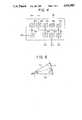
- FIGS. 8 and 9show a prior-art apparatus for controlling an A.C. elevator disclosed, for example, in Japanese Utility Model Application Laid-open No. 60-12568.
- FIG. 8is a circuit diagram of a block diagram of the control apparatus
- FIG. 9is a vector diagram.
- numeral 1designates a three-phase A.C. power source.
- 2denotes A.C. reactors connected to the A.C. power source 1.
- Numeral 3indicates a converter which converts an A.C. into a D.C. by a pulse width modulation.
- the converter 3has transistors connected at its input side to the A.C. reactors 2 to receive input currents and diodes in parallel with the transistors.
- Symbols 4A to 4Cdepict current detectors for detecting the input currents of the converter 3.
- Numeral 5designates D.C. buses connected to the output side of the converter 3
- numeral 6denotes a D.C. voltage detector for detecting a voltage between the D.C. buses 5.
- Numeral 7indicates a reference voltage setter.
- Numeral 8depicts a voltage control amplifier
- numeral 9designates a three-phase sinusoidal wave oscillator.
- Symbols 10A to 10Cdenote multipliers.
- Symbols 11A to 11Cindicate current control amplifier.
- Numeral 12depicts a saw-tooth wave generator.
- Numeral 13designates a comparator.
- Numeral 14denotes a base driving circuit for producing a signal to the buses of the transistors of the converter 3. As will be shown, the D.C. buses 5, 5 are connected to an inverter constructed in the same manner as the converter 3, and a three-phase induction motor for hoisting an elevator is connected to the output side of the inverter.
- the prior-art apparatus for controlling the A.C. elevatoris constructed as described above, and the operation of the apparatus will be described herebelow.
- the A.C. voltage from the A.C. power source 1is converted by the converter 3 into D.C., which is, in turn, supplied to the inverter, and the voltage between the D.C. buses 5 and 5 is detected by the D.C. voltage detector 6.
- the voltage control amplifier 8compares the D.C. voltage signal 6a with the output of the reference voltage setter 7 and generates a current command signal.
- the output of the voltage control amplifier 8is multiplied by the multipliers 10A to 10C by the outputs of the sinusoidal wave generator 9, and sinusoidal current command signals are generated.
- the sinusoidal current command signals from the multiplier 10A to 10Care, in turn, applied to the current control amplifiers 11A to 11C.
- the outputs of the current detectors 4A to 4Care also applied to the current control amplifiers 11A to 11C.
- the current control amplifiers 11A to 11Ccalculate and amplify deviations between the current command signals of the outputs of the multipliers 10A to 10C and the outputs of the current detectors 4A to 4C, respectively.
- the outputs of the current control amplifiers 11A to 11Care then applied to the compartor 13.
- the output of the saw-tooth wave generator 12is also applied to the comparator 13.
- the comparator 13compares the outputs of the current control amplifiers 11A to 11C with the output of the saw-tooth wave generator 12, and generates pulse-width modulation signals.
- These pulse-width modulation signalsare amplified by the base driving circuit 14, and, in turn, applied to the bases of the transistors of the converter 3 as base signals to control the converter 3, thereby controlling to maintain the voltage of the D.C. buses 5 constant.
- the current command signals applied to the bases of the transistors of the converter 3 for controlling the converter 3 in FIG. 8are sinusoidal. Accordingly, the input currents to the converters 3 also are sinusoidal, and the following vector equation is satisified.
- Vindenotes an input voltage of the converter 3
- Vacdenotes a voltage of the A.C. power source 1
- Idenotes an input current of the converter 3
- Xdenotes an impedance of the AC reactor 2.
- the present inventionhas been made in order to solve the above drawbacks and problems and has for its object to provide an apparatus for controlling an A.C. powered elevator, which can reduce the harmonic wave components of an input current without raising the voltage of A.C. buses even if a load current increases.
- Another object of the present inventionis to provide an apparatus for controlling an A.C. powered elevator, which can, additionally, reduce the harmonic wave components of an input current without raising the voltage of D.C. buses even if the power source voltage is varied.
- the apparatus for controlling power conversion from A.C. to D.C. by a convertercomprises a D.C. voltage detector connected to receive a D.C. output of the converter for detecting the D.C. side voltage of the converter, a phase detector connected to an A.C. power source for detecting the phase of the A.C. power source, and calculating means for making a first calculation of a first current command value based on the output of the D.C. voltage detector, a second calculation of the phase angle of the A.C. power source voltage based on the first current command value and a predetermined voltage value, and a third calculation of said current command values based on the phase angle of the A.C. power source voltage and an output of the phase detector.
- the apparatus for controlling an A.C. elevatorcomprises, in addition to the above, an A.C. voltage detector circuit for detecting the A.C. power source voltage to input the output of the A.C. voltage detector circuit to the calculating means instead of the predetermined value.
- phase angles of the A.C. power source voltage and the input current of the converterare calculated to determine the current command signal in the apparatus of the present invention, the phase of the input current of the converter is controlled in response in the amplitude of the input current so that the input voltage of the converter becomes substantially constant.
- the A.C. power source voltageis introduced in the calculation of the phase angle. Therefore, the phase of the input current of the converter is controlled in response to the amplitude of the A.C. power source voltage so that the input voltage of the converter becomes substantially constant.
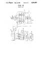
- FIG. 1is a block circuit diagram showing an embodiment of an apparatus for controlling an A.C. powered elevator according to the present invention
- FIG. 2is a circuit diagram showing an A.C. voltage detector
- FIG. 3is a circuit diagram showing a power source phase detector
- FIG. 4is a block diagram of a microcomputer
- FIG. 5is a vector diagram of voltages
- FIG. 6is a flow chart showing the program of the microcomputer
- FIG. 7is a vector diagram
- FIG. 8is a block diagram of the essential portion of a prior-art apparatus for controlling an A.C. powered elevator.
- FIG. 9is a vector diagram of the prior-art apparatus.
- FIGS. 1 to 7show an embodiment of the present invention.
- numeral 21designates a smoothing condenser connected between D.C. buses 5 and 5.
- Numeral 22denotes an inverter for converting a D.C. into a variable voltage variable frequency A.C. by pulse-width modulation, composed similarly to the converter 3.
- Numeral 23indicates an induction motor for hoisting an elevator connected to the A.C. side of the inverter 22.
- Numeral 24depicts an A.C. voltage detector for detecting the voltage of an A.C. power source 1 to produce an A.C. voltage signal 24a.
- the detector 24has, as shown in FIG. 2, a step-down transformer 24A, a three-phase full-wave rectifier 24B formed of diodes and a filter circuit 2C including a condenser and resistors.
- the voltage of the A.C. power source 1is stepped down by the step-down transformer 24A, rectified by the three-phase full-wave rectifier 24B, and smoothed by the filter 24C to produce an A.C. voltage signal 24a.
- numeral 25designates a power source phase detector circuit for detecting the phase angle of the A.C. power source 1.
- the power source phase detector circuithas a step-down transformer 24A, a comparator 25B including an operational amplifier and resistors, a phase locked loop (hereinafter referred to as a "PLL") oscillator 25C and a counter 35D.
- PLLphase locked loop
- the PLL oscillator 25Cvaries the output pulse frequency in response to the phase difference of the outputs of the comparator 25B and the counter 25D. Then, the output of the counter 25D becomes a phase angle signal 25a synchronized with the phase of the A.C. power source 1.
- numeral 26designates a microcomputer, which has, as shown in FIG. 4, a CPU 26A, a ROM 26B, a RAM 26C, analog-to-digital (hereinafter referred to as a "A/D") converters 26D, 26E, an interface (hereinafter referred to as a "I/F") circuit 26F and digital-to-analog (hereinafter referred to as a "D/A”) converters 26G to 26I.
- the A/D converters 26D, 26Eare respectively connected to the D.C. voltage detector 6 and the A.C. voltage detector 24, the I/F circuit 26F is connected to the power source phase detector 25, and the D/A converters 26G to 26I are respectively connected to current control amplifiers 11A to 11C.
- the cost of electric poweris inversely proportional to the power factor. To reduce the cost of electric power, it is desirable to keep the power factor at the highest practicable value, such as 85% or higher.
- the input voltage of the converter 3is lowered when the power factor of the input current is reduced in a range higher than the predetermined value, and the D.C. voltage can be thus decreased.
- phase of the currentis controlled so that the following equation is satisfied from FIG. 5 in order to maintain the input voltage of the converter 3 a value lower than a predetermined value irrespective of the variations in the amplitude of the load current and the voltage of the A.C. power source 1.
- ⁇denotes the phase angles of the power source voltage and the input current.
- FIG. 6is a flow chart for a program stored in the ROM 26B of the microcomputer.
- the D.C. voltage Vd detected by the D.C. voltage detector 6is read through the A/D converter 26D in step 31.
- the D.C. voltage Vdis compared with a reference value to calculate a current command value I in step 32.
- the voltage Vac of the A.C. power source 1 detected by the A.C. voltage detector 24is read through the A/D converter 26E.
- the phase angle ⁇is calculated by the equation (7).
- step 36the phase angle ⁇ t (wherein ⁇ is an angular velocity, and t is a time) of the power source voltage detected by the power source phase detector 25 is read through the I/F 26F.
- step 37the current command values i u *, i v * and i w * are calculated. ##EQU5##
- step 38the current command values i u *, i v * and i w * are respectively applied from the D/A converters 26G to 26I as outputs 26a to 26c to the current control amplifiers 11A to 11C.
- the converter 3is controlled, thereby maintaining the voltage of the D.C buses 5 constant.
- This voltageis smoothed by the smoothing condenser 21, supplied to the inverter 22 to be converted into variable voltage variable frequency voltage, and, in turn, supplied to the motor 23.
- the speed of the motor 23is controlled.
- the detailed descriptionwill be omitted.
- the calculation after the step 34is corrected.
- the phase angle ⁇ corresponding to the voltage Vac1is calculated, the voltage drop jXI is controlled as shown in FIG. 7 so that the input voltage Vin of the inverter 3 may not rise.
- the voltage detector 24has been employed. However, when the variation in the voltage of the A.C. power source 1 can be ignored, it can be sufficiently useful even if the voltage detector 24 is not used. In this case, the A.C. voltage Vac read in the step 33 is processed as a constant value.
- the phase of the input currentis controlled in response to the amplitude of the input current so that the input voltage of the converter becomes substantially constant. Therefore, the dielectric strength of the components used in the main circuit can be reduced by setting the D.C. voltage to a lower value, thereby reducing the cost of construction of the apparatus. Even if the load is varied, the harmonic wave components of the input current can be reduced.
- the A.C. power source voltageis employed in the calculation of the phase angle. Therefore, even if the A.C. power source voltage is varied, the D.C. voltage can be set to a lower value, and the harmonic wave components of the input current can be reduced.
Landscapes
- Engineering & Computer Science (AREA)
- Power Engineering (AREA)
- Automation & Control Theory (AREA)
- Control Of Ac Motors In General (AREA)
- Elevator Control (AREA)
Abstract
Description
Vin=Vac+jXI (1)
Vin=Vac×cos (2θ)+XI×sin (2θ)=Vcont (4)
φ=tan.sup.-1 XI/Vac (6)
Claims (2)
Applications Claiming Priority (2)
| Application Number | Priority Date | Filing Date | Title |
|---|---|---|---|
| JP62-36232 | 1987-02-19 | ||
| JP62036232AJPH0191696A (en) | 1987-02-19 | 1987-02-19 | AC elevator control device |
Publications (1)
| Publication Number | Publication Date |
|---|---|
| US4816985Atrue US4816985A (en) | 1989-03-28 |
Family
ID=12464027
Family Applications (1)
| Application Number | Title | Priority Date | Filing Date |
|---|---|---|---|
| US07/156,754Expired - LifetimeUS4816985A (en) | 1987-02-19 | 1988-02-18 | Apparatus for controlling an alternating current power supply |
Country Status (4)
| Country | Link |
|---|---|
| US (1) | US4816985A (en) |
| JP (1) | JPH0191696A (en) |
| KR (1) | KR920001947B1 (en) |
| CN (1) | CN1011580B (en) |
Cited By (28)
| Publication number | Priority date | Publication date | Assignee | Title |
|---|---|---|---|---|
| US4984147A (en)* | 1989-05-12 | 1991-01-08 | Mitsubishi Denki Kabushiki Kaisah | Control method for PWM converter |
| US5018058A (en)* | 1990-07-05 | 1991-05-21 | Power Management International, Inc. | High frequency AC voltage control |
| US5034874A (en)* | 1989-05-29 | 1991-07-23 | Mitsubishi Denki Kabushiki Kaisha | PWM converter apparatus |
| US5045991A (en)* | 1989-12-28 | 1991-09-03 | Sundstrand Corporation | Unity power factor AC/DC converter |
| US5091842A (en)* | 1989-04-27 | 1992-02-25 | Mitsubishi Denki Kabushiki Kaisha | Device for removing d.c. components from output of multi-phase inverter |
| US5099918A (en)* | 1989-03-14 | 1992-03-31 | Uentech Corporation | Power sources for downhole electrical heating |
| US5177677A (en)* | 1989-03-08 | 1993-01-05 | Hitachi, Ltd. | Power conversion system |
| US5255175A (en)* | 1989-05-15 | 1993-10-19 | Kabushiki Kaisha Toshiba | Power generation system having induction generator and controlled bridge rectifier |
| US5460244A (en)* | 1992-03-06 | 1995-10-24 | Mitsubishi Denki Kabushiki Kaisha | Elevator control apparatus using parallel converters and inverters with means to control circulating current |
| US5483142A (en)* | 1993-09-22 | 1996-01-09 | Allen-Bradley Company, Inc. | Precharge circuit having microprocessor-based firing angle control circuitry |
| US5491624A (en)* | 1993-06-29 | 1996-02-13 | Square D Company | AC to DC power conversion system |
| US5500575A (en)* | 1993-10-27 | 1996-03-19 | Lighting Control, Inc. | Switchmode AC power controller |
| US5680040A (en)* | 1995-06-16 | 1997-10-21 | Mitsubishi Denki Kabushiki Kaisha | System for detecting incorrect phase rotation |
| US5892674A (en)* | 1996-02-16 | 1999-04-06 | Hitachi, Ltd. | Method and apparatus for power converting AC into DC or DC into AC by converter having common phase connection |
| US6034488A (en)* | 1996-06-04 | 2000-03-07 | Lighting Control, Inc. | Electronic ballast for fluorescent lighting system including a voltage monitoring circuit |
| US20020114115A1 (en)* | 2001-02-19 | 2002-08-22 | Mitsubishi Denki Kabushiki Kaisha | Semiconductor device |
| US20020144163A1 (en)* | 2000-10-10 | 2002-10-03 | Ryan Goodfellow | System and method for highly phased power regulation using adaptive compensation control |
| US6590794B1 (en)* | 1999-10-15 | 2003-07-08 | Siemens Aktiengesellschaft | Apparatus and method for measuring current |
| US20030222459A1 (en)* | 2002-05-31 | 2003-12-04 | Martyn Harris | Capacitive control of alternator regulation |
| US20040174018A1 (en)* | 2003-03-06 | 2004-09-09 | Yasumitsu Itoh | Power generation controller for AC generator |
| US20040257050A1 (en)* | 2000-07-26 | 2004-12-23 | Zeller Peter Kilian | Method for constant-current generation and device used to carry out said method |
| US20070070660A1 (en)* | 2005-09-28 | 2007-03-29 | Tallam Rangarajan M | Method and apparatus for estimating line inductance for PWM rectifier control |
| US20070215598A1 (en)* | 2006-03-20 | 2007-09-20 | Husky Injection Molding Systems Ltd. | Controller for a heater and an associated method of use |
| US20080205093A1 (en)* | 2005-09-09 | 2008-08-28 | Siemens Aktiengesellschaft | Apparatus for Electrical Power Transmission |
| US20090033257A1 (en)* | 2005-05-20 | 2009-02-05 | Toyota Jidosha Kabushiki Kaisha | Voltage Control of Upconverter in a Motored Vehicle Drive |
| EP2063194A1 (en)* | 2007-11-20 | 2009-05-27 | LG Electronics Inc. | Motor controller of air conditioner |
| US20160218624A1 (en)* | 2013-10-16 | 2016-07-28 | Daikin Industries, Ltd. | Power converter and air conditioner |
| US11374524B2 (en)* | 2018-10-16 | 2022-06-28 | Daikin Industries, Ltd. | Power source control circuit |
Families Citing this family (3)
| Publication number | Priority date | Publication date | Assignee | Title |
|---|---|---|---|---|
| JP4334212B2 (en)* | 2002-12-26 | 2009-09-30 | 株式会社東芝 | X-ray computed tomography system |
| JP2006038531A (en)* | 2004-07-23 | 2006-02-09 | Toshiba Elevator Co Ltd | Reverse phase detection device for three phase ac power source |
| CN102351119A (en)* | 2011-09-30 | 2012-02-15 | 李必春 | Public direct-current circuit technology for alternating-current permanent-magnet synchronous variable-frequency elevator |
Citations (8)
| Publication number | Priority date | Publication date | Assignee | Title |
|---|---|---|---|---|
| US3832620A (en)* | 1973-07-26 | 1974-08-27 | Gen Electric | Regulating mode selector scheme for an electric power converter |
| US4210956A (en)* | 1977-01-05 | 1980-07-01 | Hitachi, Ltd. | Method and system of controlling high voltage direct current power transmission plants |
| US4328454A (en)* | 1979-01-10 | 1982-05-04 | Hitachi, Ltd. | Apparatus for controlling ac motor |
| US4330815A (en)* | 1979-05-04 | 1982-05-18 | Hitachi, Ltd. | DC Transmission control system |
| US4490780A (en)* | 1983-02-02 | 1984-12-25 | Allen-Bradley Company | Digital power converter |
| US4494179A (en)* | 1982-02-26 | 1985-01-15 | Tokyo Shibaura Denki Kabushiki Kaisha | Control device for a converter |
| US4626978A (en)* | 1984-07-13 | 1986-12-02 | Saphymo-Stel | Static power frequency converter |
| JPH0612568A (en)* | 1992-06-25 | 1994-01-21 | Matsushita Refrig Co Ltd | Automatic cup drink vending machine |
Family Cites Families (1)
| Publication number | Priority date | Publication date | Assignee | Title |
|---|---|---|---|---|
| JPS58222782A (en)* | 1982-06-18 | 1983-12-24 | Hitachi Ltd | Controller for pwm converter |
- 1987
- 1987-02-19JPJP62036232Apatent/JPH0191696A/enactivePending
- 1988
- 1988-01-15KRKR1019880000269Apatent/KR920001947B1/ennot_activeExpired
- 1988-02-15CNCN88100824Apatent/CN1011580B/ennot_activeExpired
- 1988-02-18USUS07/156,754patent/US4816985A/ennot_activeExpired - Lifetime
Patent Citations (8)
| Publication number | Priority date | Publication date | Assignee | Title |
|---|---|---|---|---|
| US3832620A (en)* | 1973-07-26 | 1974-08-27 | Gen Electric | Regulating mode selector scheme for an electric power converter |
| US4210956A (en)* | 1977-01-05 | 1980-07-01 | Hitachi, Ltd. | Method and system of controlling high voltage direct current power transmission plants |
| US4328454A (en)* | 1979-01-10 | 1982-05-04 | Hitachi, Ltd. | Apparatus for controlling ac motor |
| US4330815A (en)* | 1979-05-04 | 1982-05-18 | Hitachi, Ltd. | DC Transmission control system |
| US4494179A (en)* | 1982-02-26 | 1985-01-15 | Tokyo Shibaura Denki Kabushiki Kaisha | Control device for a converter |
| US4490780A (en)* | 1983-02-02 | 1984-12-25 | Allen-Bradley Company | Digital power converter |
| US4626978A (en)* | 1984-07-13 | 1986-12-02 | Saphymo-Stel | Static power frequency converter |
| JPH0612568A (en)* | 1992-06-25 | 1994-01-21 | Matsushita Refrig Co Ltd | Automatic cup drink vending machine |
Cited By (44)
| Publication number | Priority date | Publication date | Assignee | Title |
|---|---|---|---|---|
| US5177677A (en)* | 1989-03-08 | 1993-01-05 | Hitachi, Ltd. | Power conversion system |
| US5099918A (en)* | 1989-03-14 | 1992-03-31 | Uentech Corporation | Power sources for downhole electrical heating |
| US5091842A (en)* | 1989-04-27 | 1992-02-25 | Mitsubishi Denki Kabushiki Kaisha | Device for removing d.c. components from output of multi-phase inverter |
| US4984147A (en)* | 1989-05-12 | 1991-01-08 | Mitsubishi Denki Kabushiki Kaisah | Control method for PWM converter |
| US5255175A (en)* | 1989-05-15 | 1993-10-19 | Kabushiki Kaisha Toshiba | Power generation system having induction generator and controlled bridge rectifier |
| US5034874A (en)* | 1989-05-29 | 1991-07-23 | Mitsubishi Denki Kabushiki Kaisha | PWM converter apparatus |
| US5045991A (en)* | 1989-12-28 | 1991-09-03 | Sundstrand Corporation | Unity power factor AC/DC converter |
| WO1992001329A1 (en)* | 1990-07-05 | 1992-01-23 | Power Management International, Inc. | Solid state high frequency ac voltage control apparatus |
| US5018058A (en)* | 1990-07-05 | 1991-05-21 | Power Management International, Inc. | High frequency AC voltage control |
| US5460244A (en)* | 1992-03-06 | 1995-10-24 | Mitsubishi Denki Kabushiki Kaisha | Elevator control apparatus using parallel converters and inverters with means to control circulating current |
| US5491624A (en)* | 1993-06-29 | 1996-02-13 | Square D Company | AC to DC power conversion system |
| US5483142A (en)* | 1993-09-22 | 1996-01-09 | Allen-Bradley Company, Inc. | Precharge circuit having microprocessor-based firing angle control circuitry |
| US5500575A (en)* | 1993-10-27 | 1996-03-19 | Lighting Control, Inc. | Switchmode AC power controller |
| US5680040A (en)* | 1995-06-16 | 1997-10-21 | Mitsubishi Denki Kabushiki Kaisha | System for detecting incorrect phase rotation |
| US5892674A (en)* | 1996-02-16 | 1999-04-06 | Hitachi, Ltd. | Method and apparatus for power converting AC into DC or DC into AC by converter having common phase connection |
| US6034488A (en)* | 1996-06-04 | 2000-03-07 | Lighting Control, Inc. | Electronic ballast for fluorescent lighting system including a voltage monitoring circuit |
| US6590794B1 (en)* | 1999-10-15 | 2003-07-08 | Siemens Aktiengesellschaft | Apparatus and method for measuring current |
| US20040257050A1 (en)* | 2000-07-26 | 2004-12-23 | Zeller Peter Kilian | Method for constant-current generation and device used to carry out said method |
| US7211988B2 (en)* | 2000-07-26 | 2007-05-01 | Permagen Motoren- Und Generatorentechnik Gmbh | Method for constant-current generation and device used to carry out said method |
| US20020144163A1 (en)* | 2000-10-10 | 2002-10-03 | Ryan Goodfellow | System and method for highly phased power regulation using adaptive compensation control |
| US7007176B2 (en)* | 2000-10-10 | 2006-02-28 | Primarion, Inc. | System and method for highly phased power regulation using adaptive compensation control |
| US6807038B2 (en)* | 2001-02-19 | 2004-10-19 | Mitsubishi Denki Kabushiki Kaisha | Semiconductor device |
| US20020114115A1 (en)* | 2001-02-19 | 2002-08-22 | Mitsubishi Denki Kabushiki Kaisha | Semiconductor device |
| US7215098B2 (en)* | 2002-05-31 | 2007-05-08 | Bowman Power Systems Ltd. | Electrical generating system having capacitative control of alternator regulation |
| US20030222459A1 (en)* | 2002-05-31 | 2003-12-04 | Martyn Harris | Capacitive control of alternator regulation |
| US7023102B2 (en)* | 2003-03-06 | 2006-04-04 | Suzuki Motor Corporation | Power generation controller for AC generator |
| US20040174018A1 (en)* | 2003-03-06 | 2004-09-09 | Yasumitsu Itoh | Power generation controller for AC generator |
| US7923945B2 (en) | 2005-05-20 | 2011-04-12 | Toyota Jidosha Kabushiki Kaisha | Voltage control of upconverter in a motored vehicle drive |
| KR100958710B1 (en)* | 2005-05-20 | 2010-05-18 | 도요타 지도샤(주) | Load drive apparatus and motored vehicle having the same mounted thereon |
| CN101180191B (en)* | 2005-05-20 | 2011-03-23 | 丰田自动车株式会社 | Load driving equipment and electric vehicles equipped with such equipment |
| US20090033257A1 (en)* | 2005-05-20 | 2009-02-05 | Toyota Jidosha Kabushiki Kaisha | Voltage Control of Upconverter in a Motored Vehicle Drive |
| US7969755B2 (en)* | 2005-09-09 | 2011-06-28 | Siemens Aktiengesellschaft | Apparatus for electrical power transmission |
| US20080205093A1 (en)* | 2005-09-09 | 2008-08-28 | Siemens Aktiengesellschaft | Apparatus for Electrical Power Transmission |
| US20070070660A1 (en)* | 2005-09-28 | 2007-03-29 | Tallam Rangarajan M | Method and apparatus for estimating line inductance for PWM rectifier control |
| US7336509B2 (en)* | 2005-09-28 | 2008-02-26 | Rockwell Automation Technologies, Inc. | Method and apparatus for estimating line inductance for PWM rectifier control |
| US20070216055A1 (en)* | 2006-03-20 | 2007-09-20 | Husky Injection Molding Systems Ltd. | Controller for at least one heater utilized in a hot runner injection molding system and an associated method of use |
| US7618566B2 (en) | 2006-03-20 | 2009-11-17 | Husky Injection Molding Systems Ltd. | Controller for at least one heater utilized in a hot runner injection molding system and an associated method of use |
| US7418992B2 (en) | 2006-03-20 | 2008-09-02 | Husky Injection Molding Systems Ltd. | Controller for at least one heater utilized in an injection molding system and an associated method of use |
| US20070216054A1 (en)* | 2006-03-20 | 2007-09-20 | Husky Injection Molding Systems Ltd. | Controller for at lest one heater utilized in an injection molding system and an associated method of use |
| US20070215598A1 (en)* | 2006-03-20 | 2007-09-20 | Husky Injection Molding Systems Ltd. | Controller for a heater and an associated method of use |
| EP2063194A1 (en)* | 2007-11-20 | 2009-05-27 | LG Electronics Inc. | Motor controller of air conditioner |
| US20160218624A1 (en)* | 2013-10-16 | 2016-07-28 | Daikin Industries, Ltd. | Power converter and air conditioner |
| US9577534B2 (en)* | 2013-10-16 | 2017-02-21 | Daikin Industries, Ltd. | Power converter and air conditioner |
| US11374524B2 (en)* | 2018-10-16 | 2022-06-28 | Daikin Industries, Ltd. | Power source control circuit |
Also Published As
| Publication number | Publication date |
|---|---|
| KR890011769A (en) | 1989-08-22 |
| CN1011580B (en) | 1991-02-13 |
| KR920001947B1 (en) | 1992-03-07 |
| JPH0191696A (en) | 1989-04-11 |
| CN88100824A (en) | 1988-09-07 |
Similar Documents
| Publication | Publication Date | Title |
|---|---|---|
| US4816985A (en) | Apparatus for controlling an alternating current power supply | |
| KR920007073B1 (en) | Control device of induction motor | |
| KR0176909B1 (en) | Driving device of a linear compressor | |
| EP0556013B1 (en) | Energy-saving control apparatus and control method for induction motor | |
| EP0358225B1 (en) | Power converting apparatus including beat suppressor | |
| US5442271A (en) | Induction motor control apparatus providing high efficiency with rapid response to changes in load torque | |
| JPS6148356B2 (en) | ||
| JPS58133177A (en) | Method and device for controlling ac load | |
| KR0152415B1 (en) | Electric resource control device and method thereof | |
| JPH06153534A (en) | Capacitorless inverter and method for controlling the same | |
| JPS62277075A (en) | Controller for rectifier | |
| JPS6038960B2 (en) | Inverter voltage control device | |
| JP2695152B2 (en) | Rectifier power supply | |
| JPH0865810A (en) | Electric car control device | |
| JP2624790B2 (en) | Variable DC power supply | |
| JP2000270559A (en) | Variable speed device | |
| JPS5819169A (en) | Controlling method for pwm control converter | |
| JPH10164846A (en) | Control device for power conversion apparatus | |
| JP2645012B2 (en) | Motor control device | |
| JPH03256592A (en) | Pwm power converter | |
| JPH07194183A (en) | Power controller for induction motor | |
| JPH05103418A (en) | Low-voltage anomaly detection system | |
| JP2827986B2 (en) | Induction motor control method and device | |
| JPH0419796B2 (en) | ||
| JP3367312B2 (en) | Control method of PWM control self-excited rectifier |
Legal Events
| Date | Code | Title | Description |
|---|---|---|---|
| AS | Assignment | Owner name:MITSUBISHI DENKI KABUSHIKI KAISHA, 2-3, MARUNOUCHI Free format text:ASSIGNMENT OF ASSIGNORS INTEREST.;ASSIGNOR:TANAHASHI, TOORU;REEL/FRAME:004858/0097 Effective date:19880229 Owner name:MITSUBISHI DENKI KABUSHIKI KAISHA, JAPAN Free format text:ASSIGNMENT OF ASSIGNORS INTEREST;ASSIGNOR:TANAHASHI, TOORU;REEL/FRAME:004858/0097 Effective date:19880229 | |
| STCF | Information on status: patent grant | Free format text:PATENTED CASE | |
| FEPP | Fee payment procedure | Free format text:PAYOR NUMBER ASSIGNED (ORIGINAL EVENT CODE: ASPN); ENTITY STATUS OF PATENT OWNER: LARGE ENTITY | |
| FPAY | Fee payment | Year of fee payment:4 | |
| FEPP | Fee payment procedure | Free format text:PAYOR NUMBER ASSIGNED (ORIGINAL EVENT CODE: ASPN); ENTITY STATUS OF PATENT OWNER: LARGE ENTITY Free format text:PAYER NUMBER DE-ASSIGNED (ORIGINAL EVENT CODE: RMPN); ENTITY STATUS OF PATENT OWNER: LARGE ENTITY | |
| FPAY | Fee payment | Year of fee payment:8 | |
| FPAY | Fee payment | Year of fee payment:12 |