US4816975A - Photography light - Google Patents
Photography lightDownload PDFInfo
- Publication number
- US4816975A US4816975AUS07/069,506US6950687AUS4816975AUS 4816975 AUS4816975 AUS 4816975AUS 6950687 AUS6950687 AUS 6950687AUS 4816975 AUS4816975 AUS 4816975A
- Authority
- US
- United States
- Prior art keywords
- light
- reflector
- light fixture
- mirror
- reflected
- Prior art date
- Legal status (The legal status is an assumption and is not a legal conclusion. Google has not performed a legal analysis and makes no representation as to the accuracy of the status listed.)
- Expired - Fee Related
Links
- 239000011248coating agentSubstances0.000claimsabstractdescription6
- 238000000576coating methodMethods0.000claimsabstractdescription6
- NIXOWILDQLNWCW-UHFFFAOYSA-Nacrylic acid groupChemical groupC(C=C)(=O)ONIXOWILDQLNWCW-UHFFFAOYSA-N0.000claimsdescription2
- 239000011521glassSubstances0.000claims1
- 238000005286illuminationMethods0.000abstractdescription5
- 230000008859changeEffects0.000description6
- RZVAJINKPMORJF-UHFFFAOYSA-NAcetaminophenChemical compoundCC(=O)NC1=CC=C(O)C=C1RZVAJINKPMORJF-UHFFFAOYSA-N0.000description1
- 230000004075alterationEffects0.000description1
- 230000005540biological transmissionEffects0.000description1
- 238000000034methodMethods0.000description1
- 238000012986modificationMethods0.000description1
- 230000004048modificationEffects0.000description1
- 230000003287optical effectEffects0.000description1
- 230000008569processEffects0.000description1
- 239000005297pyrexSubstances0.000description1
Images


Classifications
- G—PHYSICS
- G03—PHOTOGRAPHY; CINEMATOGRAPHY; ANALOGOUS TECHNIQUES USING WAVES OTHER THAN OPTICAL WAVES; ELECTROGRAPHY; HOLOGRAPHY
- G03B—APPARATUS OR ARRANGEMENTS FOR TAKING PHOTOGRAPHS OR FOR PROJECTING OR VIEWING THEM; APPARATUS OR ARRANGEMENTS EMPLOYING ANALOGOUS TECHNIQUES USING WAVES OTHER THAN OPTICAL WAVES; ACCESSORIES THEREFOR
- G03B15/00—Special procedures for taking photographs; Apparatus therefor
- G03B15/02—Illuminating scene
- G03B15/06—Special arrangements of screening, diffusing, or reflecting devices, e.g. in studio
- F—MECHANICAL ENGINEERING; LIGHTING; HEATING; WEAPONS; BLASTING
- F21—LIGHTING
- F21W—INDEXING SCHEME ASSOCIATED WITH SUBCLASSES F21K, F21L, F21S and F21V, RELATING TO USES OR APPLICATIONS OF LIGHTING DEVICES OR SYSTEMS
- F21W2131/00—Use or application of lighting devices or systems not provided for in codes F21W2102/00-F21W2121/00
- F21W2131/40—Lighting for industrial, commercial, recreational or military use
- F21W2131/406—Lighting for industrial, commercial, recreational or military use for theatres, stages or film studios
Definitions
- the inventionrelates to photography lights, and particularly to photography lights for providing "fill" illumination.
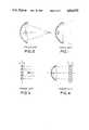
- FIGS. 1 and 2show arrangements of light fixtures which produce, respectively, a wide-angle and a spot light. While these arrangements change the intensity of light falling on an object in the photographing field, as compared to the spot light, the wide-angle light sheds a significant amount of light on the surrounding area thereby changing the balance of light in this surrounding area.
- U.S. Pat. No. 4,200,902 to Intratordiscloses a photography light which includes alternate black and white strips arranged behind a light source for controlling the amount of light reflected into the photographing field.
- the ratio of the area of the black strips to the white stripsis adjustable by the photographer to effectively vary the intensity of the light into the photographing field.
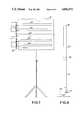
- An arrangement known in the prior artincludes a plurality of rods arranged behind a light source as in the patent to Intrator. As shown in FIG. 3, the rods are formed such that half of the surface, around the circumference thereof, is a white, reflective color, while the other half of the surface is a black absorptive color. By controlling the rotational position of the rods in synchronism, the photographer is able to control the intensity of the light into the photographing field.
- FIG. 4Another arrangement of the prior art light fixtures, as shown in FIG. 4, positions controllable shutters in front of the light fixture to control the amount of light emitted therefrom.
- each of these fixturesproduces an irregularity in the intensity of the light which may show up in the photographing field as an alternating array of light and dark stripes. In other words, neither of these lights produces uniform illumination.
- the above light fixturesradiate a great deal of heat into the photographing field.
- An object of the present inventionis to provide an adjustable photography light which exhibits uniform light intensity in the photographing field.
- Another object of the present inventionis to provide an adjustable photography light which remains cool in temperature.
- a further object of the present inventionis to provide an adjustable photography light which exhibits a uniform color temperature throughout its adjustable range.
- a photography lighthaving a light source, shutter means for controlling an amount of light from the light source, means for reflecting the light from the light source while refracting the heat therefrom, and reflector means for uniformly dispersing the light reflected by said reflecting means.
- FIG. 1shows a prior art light fixture which provides a wide angle illumination
- FIG. 2shows a prior art light fixture which provides a spot light
- FIG. 3shows a prior art light fixture in which the intensity of the light is adjusted by varying the reflectance of the reflector therein;
- FIG. 4shows a prior art light fixture in which the intensity of the light is adjusted by varying the angle of shutters positioned in front of the light source;
- FIGS. 5A-5Cshow a first embodiment of the present invention
- FIGS. 6A-6Cshow details of the round reflector used in the invention.
- FIG. 7shows a second embodiment of the present invention which uses a plurality of the light fixtures shown in FIG. 5;
- FIG. 8shows a third embodiment of the present invention.
- the subject inventionincludes a light source 10 of known design selected for producing the desired color temperature.
- a shutter or iris diaphragm 12is positioned in front of the light source 10 for controlling the amount of light passing therethrough.
- a reflector mirror 16is positioned in front of the shutter 12 for reflecting the light from the shutter 12 preferably at a 90° angle.
- the mirror 16includes a dichroic heat coating for allowing heat from the light source 10 to pass therethrough.
- the round reflector 20is made of a polished acrylic or pyrex rod 22 with an internal ground surface slot 24.
- the rod 22may have a flat or spherical entrance face 26 which may be either clear or a ground surface.
- the opposite end of the the rod 22is closed with a mirror coating 28.
- the light fixturefurther includes a housing 30 enclosing the light source 10, the shutter 12 and the mirror 16 for preventing stray light therefrom from entering the photography field.
- the opening of the shutter 12is adjusted by a control arrangement of which a control knob 14, located on the opposite side of the light fixture from the housing 30, is operatively connected to the shutter 12, by a transmission member (not shown) passing through a channel 31, connecting with the housing 30.
- a spherical reflector 32is positioned about the round reflector 20 for directing the light therefrom into the photography field. As shown in FIG. 5C, the spherical reflector 32 surrounds the rear half of the round reflector 20, and reflect light from this rear half back into the round reflector 20, or into the photography field.
- the light fixture of the subject inventionuses internal reflectance in the section A of the round reflector 20 to disperse the light reflected by the mirror 16 thereby providing uniform illumination of the ground surface of the slot 24.
- the ground surface slot 24is situated substantially at the optical center of the round reflector 20, and is thereby affected by all of the internally reflected light beams.
- the thus illuminated ground surface slot 24then emits light rays which exit through the surface of the round reflector 20. Since the power supplied to the light source 10 is kept constant, the color temperature of the light therefrom, and, consequently, that portion thereof dispersed by the round reflector 20, remains constant. Since the round reflector 20 is the apparent light source, the light therefrom, while changeable in intensity, remains diffused.
- FIG. 7shows a second embodiment of the invention in which a plurality of the light fixtures as shown in FIGS. 5A and 5B. Instead of separate reflectors 32, this embodiment uses a single reflector 40 for all of the round reflectors 20. In addition, the control arrangements for each of the shutters 12 are coupled together and are controlled by a single handle 42.
- FIG. 8shows a third embodiment of the invention in which the round reflector 20 is vertically arranged and is extended by joining several round reflectors 20 using a connecting collar 50. It should be apparent that only the last of the round reflectors 20 should include the mirror coating 28 on the end thereof.
- the light fixturemay also include a slot in the housing 30, which is positioned between the mirror 16 and the round reflector 20, into which various color filters 52 may be inserted to change the color of the light provided by the light fixture.
- the subject light fixturemay also be used as an accent light in the home environment or in industrial applications where constant color temperatures and/or cool light sources are required.
Landscapes
- Physics & Mathematics (AREA)
- General Physics & Mathematics (AREA)
- Non-Portable Lighting Devices Or Systems Thereof (AREA)
Abstract
Description
Claims (5)
Priority Applications (1)
| Application Number | Priority Date | Filing Date | Title |
|---|---|---|---|
| US07/069,506US4816975A (en) | 1987-07-02 | 1987-07-02 | Photography light |
Applications Claiming Priority (1)
| Application Number | Priority Date | Filing Date | Title |
|---|---|---|---|
| US07/069,506US4816975A (en) | 1987-07-02 | 1987-07-02 | Photography light |
Publications (1)
| Publication Number | Publication Date |
|---|---|
| US4816975Atrue US4816975A (en) | 1989-03-28 |
Family
ID=22089445
Family Applications (1)
| Application Number | Title | Priority Date | Filing Date |
|---|---|---|---|
| US07/069,506Expired - Fee RelatedUS4816975A (en) | 1987-07-02 | 1987-07-02 | Photography light |
Country Status (1)
| Country | Link |
|---|---|
| US (1) | US4816975A (en) |
Cited By (23)
| Publication number | Priority date | Publication date | Assignee | Title |
|---|---|---|---|---|
| US5021928A (en)* | 1982-09-29 | 1991-06-04 | Maurice Daniel | Flat panel illumination system |
| FR2666421A1 (en)* | 1990-09-05 | 1992-03-06 | Ruellan Yves | Projector with high-power xenon arc lamp |
| US5222793A (en)* | 1991-02-25 | 1993-06-29 | General Electric Company | Remote vehicle lighting system |
| US5295052A (en)* | 1992-10-09 | 1994-03-15 | Luxtec Corporation | Light source assembly |
| US5371660A (en)* | 1992-01-31 | 1994-12-06 | Massachusetts Institute Of Technology | Illumination system and method |
| US5559911A (en)* | 1995-01-17 | 1996-09-24 | Radiant Imaging, Inc. | Optical fiber coupler using segmented lenses |
| US5560700A (en)* | 1992-01-31 | 1996-10-01 | Massachusetts Institute Of Technology | Light coupler |
| US5661828A (en)* | 1995-01-17 | 1997-08-26 | Remote Source Lighting International | Reflector for illumination system |
| US5682448A (en)* | 1995-01-17 | 1997-10-28 | Remote Source Lighting International | Reflector and illumination system |
| US5706376A (en)* | 1995-06-02 | 1998-01-06 | Remote Source Lighting International | Multiport illuminator for macro-fibers |
| US5708737A (en)* | 1995-01-17 | 1998-01-13 | Remote Source Lighting International | Multiport illuminator mechanical design for macro-fibers |
| US5790725A (en)* | 1995-06-02 | 1998-08-04 | Remote Source Lighting Int'l, Inc. | Multiport illuminator for macro-fibers |
| US5790723A (en)* | 1995-01-17 | 1998-08-04 | Remote Source Lighting International | Multiport illuminator optic design for macro-fibers |
| US5832151A (en)* | 1995-01-17 | 1998-11-03 | Remote Source Lighting International, Inc | Reflector and illumination system |
| US5857041A (en)* | 1995-01-17 | 1999-01-05 | Remote Source Lighting International | Optical coupler and method utilizing optimal illumination reflector |
| US5862277A (en)* | 1995-01-17 | 1999-01-19 | Remote Source Lighting International, Inc. | Multiport illuminator optic design for light guides |
| US5892867A (en)* | 1995-01-17 | 1999-04-06 | Remote Source Lighting International, Inc. | Spherical multiport illuminator optic design for light guides |
| US5911020A (en)* | 1995-01-17 | 1999-06-08 | Remote Source Lighting International Inc. | Bi-planar multiport illuminator optic design for light guides |
| US6027237A (en)* | 1997-03-17 | 2000-02-22 | Remote Source Lighting International, Inc. | Air router for cooling light guide bundle |
| US6070985A (en)* | 1996-11-22 | 2000-06-06 | Remote Source Lighting International, Inc. | Multiport illuminator for light guides |
| US20100110718A1 (en)* | 2007-04-04 | 2010-05-06 | Lg Electronics Inc. | Lighting apparatus |
| US20140029265A1 (en)* | 2010-03-24 | 2014-01-30 | Jacksen International, Ltd. | Fade out optical light masking projector system |
| US8960963B1 (en)* | 2011-09-26 | 2015-02-24 | The Boeing Company | Dual wavelength focusable and steerable searchlight |
Citations (2)
| Publication number | Priority date | Publication date | Assignee | Title |
|---|---|---|---|---|
| US4233650A (en)* | 1977-10-08 | 1980-11-11 | Ernst Leitz Wetzlar Gmbh | Brightness control for fiber optical lamps |
| US4561043A (en)* | 1984-09-27 | 1985-12-24 | Thompson Gary J | Decorative light display |
- 1987
- 1987-07-02USUS07/069,506patent/US4816975A/ennot_activeExpired - Fee Related
Patent Citations (2)
| Publication number | Priority date | Publication date | Assignee | Title |
|---|---|---|---|---|
| US4233650A (en)* | 1977-10-08 | 1980-11-11 | Ernst Leitz Wetzlar Gmbh | Brightness control for fiber optical lamps |
| US4561043A (en)* | 1984-09-27 | 1985-12-24 | Thompson Gary J | Decorative light display |
Cited By (26)
| Publication number | Priority date | Publication date | Assignee | Title |
|---|---|---|---|---|
| US5021928A (en)* | 1982-09-29 | 1991-06-04 | Maurice Daniel | Flat panel illumination system |
| FR2666421A1 (en)* | 1990-09-05 | 1992-03-06 | Ruellan Yves | Projector with high-power xenon arc lamp |
| US5222793A (en)* | 1991-02-25 | 1993-06-29 | General Electric Company | Remote vehicle lighting system |
| US5560700A (en)* | 1992-01-31 | 1996-10-01 | Massachusetts Institute Of Technology | Light coupler |
| US5371660A (en)* | 1992-01-31 | 1994-12-06 | Massachusetts Institute Of Technology | Illumination system and method |
| US5295052A (en)* | 1992-10-09 | 1994-03-15 | Luxtec Corporation | Light source assembly |
| US5911020A (en)* | 1995-01-17 | 1999-06-08 | Remote Source Lighting International Inc. | Bi-planar multiport illuminator optic design for light guides |
| US5857041A (en)* | 1995-01-17 | 1999-01-05 | Remote Source Lighting International | Optical coupler and method utilizing optimal illumination reflector |
| US5682448A (en)* | 1995-01-17 | 1997-10-28 | Remote Source Lighting International | Reflector and illumination system |
| US5559911A (en)* | 1995-01-17 | 1996-09-24 | Radiant Imaging, Inc. | Optical fiber coupler using segmented lenses |
| US5708737A (en)* | 1995-01-17 | 1998-01-13 | Remote Source Lighting International | Multiport illuminator mechanical design for macro-fibers |
| US5751870A (en)* | 1995-01-17 | 1998-05-12 | Remote Source Lighting International, Inc. | Optical fiber lensed illumination coupler |
| US5892867A (en)* | 1995-01-17 | 1999-04-06 | Remote Source Lighting International, Inc. | Spherical multiport illuminator optic design for light guides |
| US5790723A (en)* | 1995-01-17 | 1998-08-04 | Remote Source Lighting International | Multiport illuminator optic design for macro-fibers |
| US5832151A (en)* | 1995-01-17 | 1998-11-03 | Remote Source Lighting International, Inc | Reflector and illumination system |
| US5661828A (en)* | 1995-01-17 | 1997-08-26 | Remote Source Lighting International | Reflector for illumination system |
| US5862277A (en)* | 1995-01-17 | 1999-01-19 | Remote Source Lighting International, Inc. | Multiport illuminator optic design for light guides |
| US5790725A (en)* | 1995-06-02 | 1998-08-04 | Remote Source Lighting Int'l, Inc. | Multiport illuminator for macro-fibers |
| US5706376A (en)* | 1995-06-02 | 1998-01-06 | Remote Source Lighting International | Multiport illuminator for macro-fibers |
| US6070985A (en)* | 1996-11-22 | 2000-06-06 | Remote Source Lighting International, Inc. | Multiport illuminator for light guides |
| US6086234A (en)* | 1997-01-31 | 2000-07-11 | Remote Source Lighting International, Inc. | Parabolic and spherical multiport illuminators for light guides |
| US6027237A (en)* | 1997-03-17 | 2000-02-22 | Remote Source Lighting International, Inc. | Air router for cooling light guide bundle |
| US20100110718A1 (en)* | 2007-04-04 | 2010-05-06 | Lg Electronics Inc. | Lighting apparatus |
| US8136973B2 (en)* | 2007-04-04 | 2012-03-20 | Lg Electronics Inc. | Lighting apparatus |
| US20140029265A1 (en)* | 2010-03-24 | 2014-01-30 | Jacksen International, Ltd. | Fade out optical light masking projector system |
| US8960963B1 (en)* | 2011-09-26 | 2015-02-24 | The Boeing Company | Dual wavelength focusable and steerable searchlight |
Similar Documents
| Publication | Publication Date | Title |
|---|---|---|
| US4816975A (en) | Photography light | |
| FI107077B (en) | Lighting systems for lighting devices, projectors and magnifiers | |
| US4916579A (en) | Gradient index zoom illuminator | |
| US5051872A (en) | Hemispherical non-glare illuminator | |
| US4293892A (en) | Zoom light apparatus | |
| US4729065A (en) | Photography light | |
| US4384769A (en) | Illuminating system for test projector | |
| US7223002B2 (en) | Hybrid fiber optic framing projector | |
| RU2293250C2 (en) | Searchlight with fresnel lens | |
| KR100209848B1 (en) | Luminaire with uniform intensity profile reflector | |
| US20080137345A1 (en) | Par² lighting fixture | |
| US4361863A (en) | Illuminating device having a curved optical conductor | |
| US4194234A (en) | Simultaneous multi directional single source multiple reflector electronic photo flash unit | |
| US6572246B1 (en) | Lighting device | |
| US7004588B2 (en) | Planetarium and point light source for use in same | |
| RU2300048C2 (en) | Fresnel-lens searchlight | |
| US4019042A (en) | Lighting device for photograph or motion-picture photography | |
| US4220982A (en) | High intensity illumination light table | |
| US4545007A (en) | Luminaire with lenticular lens | |
| CN109424895A (en) | Thermal protection and homogenization systems for lighting apparatus | |
| US4129372A (en) | Light mixing apparatus and photographic enlarger embodying same | |
| JP4199727B2 (en) | Fresnel lens spotlight | |
| US4292663A (en) | High intensity illumination light table | |
| US3747488A (en) | Photographic motion picture apparatus | |
| JPH02167450A (en) | Hemispherical non-glare lighting apparatus |
Legal Events
| Date | Code | Title | Description |
|---|---|---|---|
| AS | Assignment | Owner name:ARRIFLEX CORPORATION, 500 ROUTE 303, BLAVELT, NEW Free format text:ASSIGNMENT OF ASSIGNORS INTEREST.;ASSIGNORS:BAHNEMANN, VOLKER W.;LOTH, STANISLAW;REEL/FRAME:004741/0027 Effective date:19870629 Owner name:ARRIFLEX CORPORATION,NEW YORK Free format text:ASSIGNMENT OF ASSIGNORS INTEREST;ASSIGNORS:BAHNEMANN, VOLKER W.;LOTH, STANISLAW;REEL/FRAME:004741/0027 Effective date:19870629 | |
| REMI | Maintenance fee reminder mailed | ||
| FEPP | Fee payment procedure | Free format text:PAYOR NUMBER ASSIGNED (ORIGINAL EVENT CODE: ASPN); ENTITY STATUS OF PATENT OWNER: LARGE ENTITY | |
| FPAY | Fee payment | Year of fee payment:4 | |
| SULP | Surcharge for late payment | ||
| FPAY | Fee payment | Year of fee payment:8 | |
| FEPP | Fee payment procedure | Free format text:PAYOR NUMBER ASSIGNED (ORIGINAL EVENT CODE: ASPN); ENTITY STATUS OF PATENT OWNER: LARGE ENTITY Free format text:PAYER NUMBER DE-ASSIGNED (ORIGINAL EVENT CODE: RMPN); ENTITY STATUS OF PATENT OWNER: LARGE ENTITY | |
| REMI | Maintenance fee reminder mailed | ||
| LAPS | Lapse for failure to pay maintenance fees | ||
| FP | Lapsed due to failure to pay maintenance fee | Effective date:20010328 | |
| STCH | Information on status: patent discontinuation | Free format text:PATENT EXPIRED DUE TO NONPAYMENT OF MAINTENANCE FEES UNDER 37 CFR 1.362 |