US4816882A - Power MOS transistor with equipotential ring - Google Patents
Power MOS transistor with equipotential ringDownload PDFInfo
- Publication number
- US4816882A US4816882AUS07/138,989US13898987AUS4816882AUS 4816882 AUS4816882 AUS 4816882AUS 13898987 AUS13898987 AUS 13898987AUS 4816882 AUS4816882 AUS 4816882A
- Authority
- US
- United States
- Prior art keywords
- semiconductor region
- transistor
- region
- layer
- conductive
- Prior art date
- Legal status (The legal status is an assumption and is not a legal conclusion. Google has not performed a legal analysis and makes no representation as to the accuracy of the status listed.)
- Expired - Lifetime
Links
Images


Classifications
- H—ELECTRICITY
- H10—SEMICONDUCTOR DEVICES; ELECTRIC SOLID-STATE DEVICES NOT OTHERWISE PROVIDED FOR
- H10D—INORGANIC ELECTRIC SEMICONDUCTOR DEVICES
- H10D30/00—Field-effect transistors [FET]
- H10D30/60—Insulated-gate field-effect transistors [IGFET]
- H10D30/64—Double-diffused metal-oxide semiconductor [DMOS] FETs
- H10D30/66—Vertical DMOS [VDMOS] FETs
- H—ELECTRICITY
- H01—ELECTRIC ELEMENTS
- H01L—SEMICONDUCTOR DEVICES NOT COVERED BY CLASS H10
- H01L21/00—Processes or apparatus adapted for the manufacture or treatment of semiconductor or solid state devices or of parts thereof
- H01L21/02—Manufacture or treatment of semiconductor devices or of parts thereof
- H01L21/04—Manufacture or treatment of semiconductor devices or of parts thereof the devices having potential barriers, e.g. a PN junction, depletion layer or carrier concentration layer
- H01L21/18—Manufacture or treatment of semiconductor devices or of parts thereof the devices having potential barriers, e.g. a PN junction, depletion layer or carrier concentration layer the devices having semiconductor bodies comprising elements of Group IV of the Periodic Table or AIIIBV compounds with or without impurities, e.g. doping materials
- H01L21/28—Manufacture of electrodes on semiconductor bodies using processes or apparatus not provided for in groups H01L21/20 - H01L21/268
- H01L21/28008—Making conductor-insulator-semiconductor electrodes
- H01L21/28017—Making conductor-insulator-semiconductor electrodes the insulator being formed after the semiconductor body, the semiconductor being silicon
- H01L21/28158—Making the insulator
- H01L21/28167—Making the insulator on single crystalline silicon, e.g. using a liquid, i.e. chemical oxidation
- H01L21/28202—Making the insulator on single crystalline silicon, e.g. using a liquid, i.e. chemical oxidation in a nitrogen-containing ambient, e.g. nitride deposition, growth, oxynitridation, NH3 nitridation, N2O oxidation, thermal nitridation, RTN, plasma nitridation, RPN
- H—ELECTRICITY
- H01—ELECTRIC ELEMENTS
- H01L—SEMICONDUCTOR DEVICES NOT COVERED BY CLASS H10
- H01L21/00—Processes or apparatus adapted for the manufacture or treatment of semiconductor or solid state devices or of parts thereof
- H01L21/70—Manufacture or treatment of devices consisting of a plurality of solid state components formed in or on a common substrate or of parts thereof; Manufacture of integrated circuit devices or of parts thereof
- H01L21/71—Manufacture of specific parts of devices defined in group H01L21/70
- H01L21/768—Applying interconnections to be used for carrying current between separate components within a device comprising conductors and dielectrics
- H01L21/76897—Formation of self-aligned vias or contact plugs, i.e. involving a lithographically uncritical step
- H—ELECTRICITY
- H10—SEMICONDUCTOR DEVICES; ELECTRIC SOLID-STATE DEVICES NOT OTHERWISE PROVIDED FOR
- H10D—INORGANIC ELECTRIC SEMICONDUCTOR DEVICES
- H10D12/00—Bipolar devices controlled by the field effect, e.g. insulated-gate bipolar transistors [IGBT]
- H10D12/01—Manufacture or treatment
- H10D12/031—Manufacture or treatment of IGBTs
- H10D12/032—Manufacture or treatment of IGBTs of vertical IGBTs
- H—ELECTRICITY
- H10—SEMICONDUCTOR DEVICES; ELECTRIC SOLID-STATE DEVICES NOT OTHERWISE PROVIDED FOR
- H10D—INORGANIC ELECTRIC SEMICONDUCTOR DEVICES
- H10D30/00—Field-effect transistors [FET]
- H10D30/01—Manufacture or treatment
- H10D30/021—Manufacture or treatment of FETs having insulated gates [IGFET]
- H10D30/028—Manufacture or treatment of FETs having insulated gates [IGFET] of double-diffused metal oxide semiconductor [DMOS] FETs
- H10D30/0291—Manufacture or treatment of FETs having insulated gates [IGFET] of double-diffused metal oxide semiconductor [DMOS] FETs of vertical DMOS [VDMOS] FETs
- H—ELECTRICITY
- H10—SEMICONDUCTOR DEVICES; ELECTRIC SOLID-STATE DEVICES NOT OTHERWISE PROVIDED FOR
- H10D—INORGANIC ELECTRIC SEMICONDUCTOR DEVICES
- H10D64/00—Electrodes of devices having potential barriers
- H10D64/60—Electrodes characterised by their materials
- H10D64/66—Electrodes having a conductor capacitively coupled to a semiconductor by an insulator, e.g. MIS electrodes
- H10D64/68—Electrodes having a conductor capacitively coupled to a semiconductor by an insulator, e.g. MIS electrodes characterised by the insulator, e.g. by the gate insulator
- H10D64/681—Electrodes having a conductor capacitively coupled to a semiconductor by an insulator, e.g. MIS electrodes characterised by the insulator, e.g. by the gate insulator having a compositional variation, e.g. multilayered
- H10D64/685—Electrodes having a conductor capacitively coupled to a semiconductor by an insulator, e.g. MIS electrodes characterised by the insulator, e.g. by the gate insulator having a compositional variation, e.g. multilayered being perpendicular to the channel plane
- H—ELECTRICITY
- H10—SEMICONDUCTOR DEVICES; ELECTRIC SOLID-STATE DEVICES NOT OTHERWISE PROVIDED FOR
- H10D—INORGANIC ELECTRIC SEMICONDUCTOR DEVICES
- H10D64/00—Electrodes of devices having potential barriers
- H10D64/60—Electrodes characterised by their materials
- H10D64/66—Electrodes having a conductor capacitively coupled to a semiconductor by an insulator, e.g. MIS electrodes
- H10D64/68—Electrodes having a conductor capacitively coupled to a semiconductor by an insulator, e.g. MIS electrodes characterised by the insulator, e.g. by the gate insulator
- H10D64/693—Electrodes having a conductor capacitively coupled to a semiconductor by an insulator, e.g. MIS electrodes characterised by the insulator, e.g. by the gate insulator the insulator comprising nitrogen, e.g. nitrides, oxynitrides or nitrogen-doped materials
- H—ELECTRICITY
- H10—SEMICONDUCTOR DEVICES; ELECTRIC SOLID-STATE DEVICES NOT OTHERWISE PROVIDED FOR
- H10D—INORGANIC ELECTRIC SEMICONDUCTOR DEVICES
- H10D64/00—Electrodes of devices having potential barriers
- H10D64/60—Electrodes characterised by their materials
- H10D64/66—Electrodes having a conductor capacitively coupled to a semiconductor by an insulator, e.g. MIS electrodes
- H10D64/68—Electrodes having a conductor capacitively coupled to a semiconductor by an insulator, e.g. MIS electrodes characterised by the insulator, e.g. by the gate insulator
- H10D64/681—Electrodes having a conductor capacitively coupled to a semiconductor by an insulator, e.g. MIS electrodes characterised by the insulator, e.g. by the gate insulator having a compositional variation, e.g. multilayered
Definitions
- This inventionrelates to MOS transistors and more specifically to methods for manufacturing MOS transistors with a minimum number of masking steps.
- the inventionalso relates to double diffused MOS ("DMOS”) transistors.
- a DMOS transistoris a MOS transistor having a channel length defined by the difference in diffusion of sequentially introduced impurities from a common edge or boundary.
- a prior art process for manufacturing a DMOS transistoris discussed in U.S. Pat. No. 4,443,931, issued to Baliga, et al., incorporated herein by reference. It is known in the art that it is desirable to manufacture DMOS transistors while minimizing the number of masks used. One reason for this is that by minimizing the numbers of masks, the number of alignment steps is also minimized and therefore the need to accommodate alignment tolerances is minimized. As is known in the art, if the need to accommodate alignment tolerances is minimized, the size and cost of the resulting transistor is minimized.
- Another reason for minimizing the number of masking stepsis that the complexity of the manufacturing process is correspondingly reduced and thus the cost of producing the transistor is also reduced.
- a method for manufacturing a DMOS transistor in accordance with the present inventionincludes the step of providing a gate insulation layer on a semiconductor substrate.
- the semiconductor substrateis typically N type silicon and the gate insulation layer typically comprises a silicon nitride layer formed on a silicon dioxide layer.
- a gateis then formed on the gate insulation layer.
- the gateis polycrystalline silicon and is formed by depositing a polycrystalline silicon layer on the gate insulation layer and using a first photolithographic mask to protect portions of the polycrystalline silicon layer while the exposed portions of the polycrystalline silicon layer are removed.
- the resulting gateis covered with a second insulation layer which in on embodiment comprises silicon dioxide.
- a second photolithographic maskis formed on the wafer.
- the second maskincludes both a first window region defining the deep body region of the DMOS transistor and a second window region defining the gate contact.
- the portion of the second insulation layer within the second window regionis removed.
- the portion of the silicon nitride layer within the first window regionis also removed and the underlying portion of the semiconductor substrate is implanted with a P type dopant, thereby forming the deep body region.
- a silicon dioxide layeris then formed within the second window region, typically by thermal oxidation. Of importance, the thickness of the silicon dioxide within the first region also increases during this process.
- the exposed portion of the silicon nitride layer and the underlying silicon dioxide layerare then removed using a blanket etching process which does not require additional masking. At the conclusion of the blanket etching process, however, the silicon dioxide formed on the gate and the silicon dioxide formed above the deep body region remain.
- the silicon dioxide above the deep body regionserves as an oxide mask which defines part of a subsequently formed source region.
- P type dopantsare then implanted into the semiconductor substrate to form the body region of the DMOS transistor. Thereafter, N type dopants are implanted into the semiconductor substrate to form the source region.
- the oxide mask grown over the deep body regionprevents the underlying deep body region from being predoped or implanted with N type impurities.
- the lateral extent of the source and body regionsis defined by the edge of the gate and the oxide mask. Therefore, it is not necessary to use an extra masking step to define the source and body regions of the DMOS transistor.
- the oxide mask above the deep body region, the silicon dioxide within the second window, and any silicon dioxide formed above the source region during source and body drive-inare removed with a blanket etching process.
- a conductive layer(typically metal) is then formed on the surface of the wafer.
- a third photolithographic maskis applied to the wafer in order to pattern the conductive layer to form a gate lead and a source/body lead.
- the waferis then coated with a passivation layer of material such as silicon nitride or silicon dioxide at a low temperature (typically less than 450° C.).
- a fourth photolithographic maskis used to define regions where the passivation layer is to be removed, e.g. bonding pad regions.
- the above described processrequires only four photolithographic masks. Accordingly, the process is simpler than prior art DMOS manufacturing processes. Further, the need to increase the transistor size in order to allow for misalignment of the various photolithographic masks is reduced.
- the transistoris laterally surrounded by an equipotential ring (EQR).
- EQRis a region of material surrounding a semiconductor device such that all points within the region are at the same electrical potential.
- the EQRincludes a P region (formed concurrently with the body region), an N+ region within the P region (formed concurrently with the source region) and a conductive ring formed on the N+ region (formed concurrently with the gate lead and the source/body lead).
- the conductive ringis electrically coupled to the substrate, the P region, and the N+ region, and is biased at the same voltage as the transistor drain. Alternatively, the N+ region can be omitted.
- the EQRenhances the reliability of the DMOS transistor. Of importance, the EQR is formed without any extra masking steps:
- the transistoris laterally surrounded by an EQR comprising a P+ region (formed concurrently with the deep body region) and a conductive layer (formed concurrently with the gate lead and the source/body lead) formed on the P+ region.
- the conductive layer and P+ regionare electrically shorted to the substrate.
- FIGS. 1 to 9illustrate a portion of a DMOS transistor during various steps of a manufacturing process in accordance with the present invention.
- FIGS. 10 to 19illustrate the types of termination available.
- a process in accordance with the present inventionbegins with the step of forming a silicon dioxide layer 12 on a semiconductor wafer 10 (FIG. 1).
- wafer 10consists of a layer of N type epitaxial silicon having a conductivity of about 1.5 ohm-centimeters, and a thickness of about 12 ⁇ m, formed on a heavily doped substrate.
- N type epitaxial siliconhaving a conductivity of about 1.5 ohm-centimeters, and a thickness of about 12 ⁇ m, formed on a heavily doped substrate.
- other semiconductor materials and materials having other conductivities and conductivity typesare also appropriate.
- the term "wafer"includes the substrate and all layers formed directly or indirectly on the substrate.
- Silicon dioxide layer 12is typically thermally grown to a thickness of about 50 nanometers (nm). A silicon nitride layer 14 is then formed on silicon dioxide layer 12. Silicon nitride layer 14 is also typically about 50 nm thick and typically is formed by chemical vapor deposition. As will be discussed in greater detail below, silicon dioxide layer 12 and silicon nitride layer 14 serve as gate insulation for a subsequently formed DMOS transistor.
- a polycrystalline silicon layer 16is then formed on silicon nitride layer 14.
- polycrystalline silicon layer 16is formed to a thickness of about 500 nm by chemical vapor deposition.
- polycrystalline silicon layer 16serves as the gate of the DMOS transistor.
- Polycrystalline silicon layer 16is then doped to a sheet resistance of about 15 ohms per square with an N type dopant such as phosphorus.
- Polycrystalline silicon layer 16is then covered with a photoresist layer 18 which is then patterned in a conventional manner, thereby exposing portions 16a to 16d of polycrystalline silicon layer 16. Exposed portions 16a to 16d of polycrystalline silicon layer 16 are then removed, thereby leaving polycrystalline silicon gates 16e and 16f and a field plate 16g as illustrated in FIG. 2.
- gates 16e and 16f and field plate 16gare of a material other than polycrystalline silicon, e.g. a metal such as refractory metal or silicide.
- polycrystalline silicon gates 16eand 16fappear as separate structures, in one embodiment they are a single contiguous polycrystalline silicon gate 17 joined outside the cross section of FIG. 2.
- gates 16e and 16fare not a single contiguous region. However, in such an embodiment, gates 16e and 16f can be electrically connected together with a subsequently formed conductive layer.
- field plate 16gsurrounds the transistor and defines a subsequently formed EQR which surrounds field plate 16g.
- photoresist layer 18serves as a first mask for defining the gate of the DMOS transistor, a field limiting ring, and an EQR surrounding the transistor.
- silicon dioxide layer 20is thermally grown to a thickness of about 500 nm.
- window region 22adefines an electrical contact to polycrystalline silicon gate 17 while window regions 22b and 22c define a P+ deep body region of the DMOS transistor.
- portion 20a of silicon dioxide layer 20 within window region 22ais removed and the portions of silicon nitride layer 14 within window regions 22b and 22c are removed.
- portion 20ais removed by placing the wafer in a buffered HF solution.
- photoresist layer 22protects the underlying portions of silicon dioxide layer 20.
- the portion of silicon dioxide layer 20 within window region 22ais unprotected and therefore is removed by the HF solution.
- an oxidized nitride skintypically formed to a thickness of 5 to 10 nm during the preceding process steps within window regions 22b and 22c, is also removed by the HF solution.
- wafer 10is removed from the buffered HF solution and placed, for example, in a phosphoric acid solution which removes the portions of silicon nitride layer 14 within window regions 22b and 22c, thereby forming window regions 14a and 14b. Wafer 10 is then removed from the phosphoric acid solution and photoresist layer 22 is removed. The resulting structure is illustrated in FIG. 5.
- etchinginstead of using an HF solution and phosphoric acid to etch silicon dioxide layer 20 and silicon nitride layer 14, respectively, plasma etching, reactive ion etching, or ion milling are used.
- P+ deep body regions 24are formed in the semiconductor material within the wafer 10, e.g., by implanting P type ions in the portion of wafer 10 within window regions 14a and 14b.
- boron ionsare implanted with a dosage of about 2 ⁇ 10 14 /cm 2 and an implant energy of about 40 Kev.
- the dosagemay be as much as 10 16 /cm 2 (Of importance, the implant energy and dose are selected to guarantee that ions are not implanted into the portions of the wafer covered by both silicon dioxide layer 12 and silicon nitride layer 14.) Although during this process some ions are also implanted into polycrystalline silicon gate 17 where silicon dioxide layer 20 has been removed, because of the high N type dopant concentration in polycrystalline silicon gate 17, the gate conductivity is not significantly changed during this process. It is also noted that the portions of silicon dioxide layer 12 within window regions 14a and 14b prevent unwanted introduction of impurities into the semiconductor material within window regions 14a and 14b and prevent unwanted loss of boron during subsequent high temperature processing steps.
- a thin silicon dioxide layer 20b(typically about 50 nm thick) is formed on polycrystalline silicon 16e.
- portions 25 of silicon dioxide layer 12 above P+ deep body region 24also increase in thickness.
- silicon dioxide layers 20b and 25prevent impurities from diffusing out of gate 17 and into the substrate or epitaxial layer within wafer 10.
- FIG. 6aillustrates in plan view a portion of the transistor at this point in the manufacturing process. Region 24 and layer 20 are not shown in FIG. 6a to simplify the illustration.
- the portions of silicon nitride layer 14 not covered by gate 17 or polycrystalline silicon ring 16gare then removed. In one embodiment this is done by placing the wafer in a phosphoric acid solution. However, the exposed portions of silicon nitride layer 14 can be removed in other ways as well, e.g., reactive ion etching or plasma etching. Silicon dioxide layer 20b and the exposed portions of silicon dioxide layer 12 are then removed by placing the wafer in a buffered HF solution. In other embodiments, layer 20b and the exposed portions of silicon dioxide layer 12 are removed with plasma etching or reactive ion etching.
- silicon dioxide layers 20 and 25remain largely intact during this etching process.
- the portions of silicon nitride layer 14 and silicon dioxide layer 12 underneath gate 17 and polycrystalline silicon ring 16galso remain.
- only two photolithographic maskshave been applied to the wafer.
- P type body region 26is formed, e.g. by ion implantation.
- boron ionsare implanted into wafer 10 with a dosage of about 5 ⁇ 10 13 /cm 2 and an implant energy of approximately 50 Kev.
- the lateral extent of P type body region 26is defined by edges 27 of gate 17. Therefore, no additional photolithographic masks or alignment steps are required during formation of body region 26.
- the waferis then subjected to a drive-in process.
- a P type region 26ais formed concurrently with body region 26. However, as described below, P region 26a does not serve as a body region, but rather as part of an EQR.
- N+ source regions 28are formed, e.g. by ion implantation.
- arsenic ionsare implanted into wafer 10 with a dosage of about 5 ⁇ 10 15 /cm 2 and an implant energy of about 40 Kev. Phosphorus ions may be used instead of arsenic.
- the lateral extent of N+ source region 28is also defined by edges 27 of gate 17 and the edge of silicon dioxide 25.
- the waferis then subjected to another drive-in process. Thereafter, silicon dioxide 25 and any silicon dioxide formed above source regions 28 or within window 22a during the same drive-in process is removed in a blanket etching process, e.g. by placing the wafer in a buffered HF solution.
- N+ region 28ais formed concurrently with N+ source region 28. However, as described below, N+ region 28a does not serve as a source region but rather as part of the EQR.
- Conductive layer 30is typically a metal layer such as aluminum or an alloy of aluminum. In other embodiments, conductive layer 30 is another metal. Conductive layer 30 serves as a source/body lead for the transistor as well as a gate lead.
- the waferis then covered with a photoresist layer 32 which is patterned in a conventional manner, thereby exposing portions of conductive layer 30. The exposed portions of conductive layer 30 are then removed as illustrated in FIG. 8.
- Photoresist layer 32is then removed and the wafer is covered with a passivating layer of insulation such as plasma deposited silicon nitride layer 34.
- layer 34is silicon dioxide.
- Portions of conductive layer 30extend to an area on the wafer where bonding pads are formed (not shown).
- Passivating layer 34is patterned by applying a fourth photolithographic mask to the wafer.
- the fourth photolithographic maskincludes window regions exposing the portions of the passivating layer 34 above the bonding pads. The exposed portions of passivating layer 34 are then removed, thereby exposing the portions of conductive layer 30 at the bonding pad.
- a conductive layer 36(also typically a metal such as aluminum is formed on the bottom of the wafer (FIG. 9). Conductive layer 36 serves as a drain contact, and is typically not patterned.
- a portion 30a of conductive layer 30(the EQR) is then shorted to substrate 10 and P region 26a. In one embodiment, this is accomplished by applying a high voltage to portion 30s of conductive layer 30 relative to substrate 10. Portion 30a is typically shorted to substrate 10 and P region 26a during wafer sort. (Wafer sort is the electrical testing of devices formed in the wafer before the wafer is cut into separate devices.) In another embodiment, the leakage of the scribe "cut” or “saw” provides sufficient current flow. As mentioned above, the EQR is formed at the periphery of the transistor. As is known in the art, EQRs enhance reliability of a transistor. EQRs are described in "Surface Breakdown In Silicon Planar Diodes Equipped With Field Plate” by Conti et al., published in Solid State Electronics in 1972, Vol. 15, and incorporated herein by reference.
- polycrystalline ring 16gserves as a field plate.
- Field plate 16gis typically electrically insulated from the other structures formed on the wafer.
- a plurality of polycrystalline silicon field platessurround the transistor to further enhance transistor reliability.
- the field platesare formed by the same process as is polycrystalline field plate 16.
- a process for manufacturing a DMOS transistor requiring only four photolithographic maskshas been described in detail.
- the processis simple and minimizes the requirement of alignment tolerances.
- a transistor manufactured with the present processcan be manufactured on a smaller surface area than prior art transistors.
- the gate to gate distancee.g. from polycrystalline silicon 16e to 16f
- this distancecan be reduced to about 22 to 28 ⁇ m. This represents a savings of about 20% of the surface area of a transistor using a plurality of square cells.
- insulated gate bipolar transistorIn an alternative embodiment, the above-described process is used to form an insulated gate bipolar transistor.
- source 28, body 26 and deep body region 24are formed in an N type epitaxial layer which in turn is formed on a P+ substrate.
- insulated gate transistorThe operation of insulated gate transistor is described in detail in "The Insulated Gate Transistor: A New Three-Terminal MOS-Controlled Bipolar Device," by Baliga et al., published in IEEE Transactions on Electron Devices, Vol. ED-31., No. 6, in June 1984, and incorporated herein by reference.
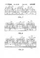
- FIG. 10illustrates a transistor constructed in accordance with another embodiment of our invention.
- the difference between the transistor of FIG. 10 and the transistor of FIG. 9is that the transistor is laterally surrounded by a P+ deep body region 24a.
- P+ deep body region 24ais formed concurrently with and electrically connected to P+ regions 24.
- P+ body region 24aserves as a device perimeter region, and is in physical contact with source region 28 and body region 26.
- P+ region 24ais laterally surrounded by field plate 16g, metallization 30a, N+ region 28a and P region 26a as described above.
- the advantage of this device termination over that shown in FIG. 9is that: first, the termiantion with P+ region 24a may have a higher breakdown voltage. But, second, and more important, the use of the P+ region 24a at the perimeter may give a device with greater ruggedness, since any injected charge is shorted directly to the source, and is not able to turn on the parasitic NPN transistor.
- FIG. 10The device of FIG. 10 is formed using the same process sequence as discussed above except that mask 18 is patterned so that field plate 16g is closer to gate structure 16f, e.g. as illustrated in attached FIG. 10a.
- FIG. 10aillustrates the device of FIG. 10 at the same process step as FIG. 2.
- mask 22is patterned so that window region 14b is formed adjacent field limiting ring 16g (see FIG. 10b, which illustrates the device of FIG. 10 at the same process step as FIG. 4).
- device processingis as described above with relation to FIGS. 1-9.
- FIG. 11illustrates another embodiment of the invention, similar to the embodiment of FIG. 10 except that instead of surrounding the transistor with an EQR including N+ region 28a and P region 26a and metallization 30a the transistor is surrounded by an EQR including P+ region 24b (formed concurrently with regions 24a and 24) and metallization layer 30a. Region 24b is not electrically connected to regions 24 or 24a.
- the transistor of FIG. 11is formed using the same process sequences discussed above except that mask 22 is patterned to define a window region at the periphery of the wafer 14c, e.g. as illustrated in FIG. 11a. (FIG. 11a illustrates a transistor at the process step illustrated by FIG. 4.) Thus, P+ region 24b is formed at the perimeter of the transistor.
- P+ region 24bis electrically contacted by EQR metallization layer 30a which in turn is electrically shorted to N type semiconductor material within wafer 10 by applying a high voltage to metal 30a.
- the leakage current of the scribe "cut” or “saw”provides sufficient current flow.
- FIG. 12illustrates another embodiment of the invention.
- the transistor of FIG. 12is the same as that of FIG. 10, with the addition of two field limiting rings 24c and 24d, and additional floating field plates 16h and 16i, all laterally surounding the transistor.
- Field limiting rings 24c and 24dare P+ regions formed in the wafer 10 concurrently with P+ regions 24 and 24a.
- Floating field plates 16h and 16iare insulated polycrystalline (or other conductor) structures formed at the same time as gates 16eand 16f and field plate 16g.
- the transistor of FIG. 12is formed using the same process sequence as described above, except that (1) mask 18 is patterned to create additional insulated polycrystalline floating field plates 16h and 16i; and (2) mask 22 is patterned to create two additional P+ regions 24c and 24d, separated by floating field plate 16h. Also, the die area of the transistor may need to be increased to accommodate the additional structures.
- FIG. 13shows a variant of the transistor depicted in FIG. 12.
- the variationis that the transistor is surrounded by an EQR structure including a P+ region 24b and EQR metallization 30a. This is the same EQR structure as described above for the transistor shown in FIG. 11.
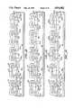
- FIG. 14Another embodiment, very similar to that of FIG. 12, is shown in FIG. 14.
- the difference between the transistor of FIG. 14 and the transistor of FIG. 12is that the transistor of FIG. 14 provides electrical connections, by means of metallization 30b, 30c and 30d, respectively, from region 24a to field plate 16g, from field limiting ring 24c to field plate 16h, and from field limiting ring 24d to field plate 16i.
- field plates 16g, 16h, and 16iare not electrically insulated in this embodiment.
- the electrical contact to field plates 16g, 16h, and 16iis accomplished by patterning mask 22 to leave a window in insulating layer 20 on top of polycrystalline silicon layer 16g, 16h and 16i.
- metal layer 30is patterned so as to form the desired connections 30b, 30c, and 30d between the regions 24a, 24c, and 24d and the adjacent field plates 16g, 16h and 16i.
- the transistor of FIG. 14is otherwise formed using the same process sequence as discussed above.
- FIG. 15depicts a variation on the transistor shown in FIG. 14.
- the transistoris surrounded only by P+ region 24b and EQR metallization 30a, the same EQR structure as the transistor shown in FIG. 10.
- P+ region 24bis formed at the same time as are regions 24, 24a, 24c, and 24d.
- FIG. 16Another embodiment as shown in FIG. 16 is similar to that shown in FIG. 12, including the floating field plates and field limiting rings, except that the field limiting rings are comprised of P regions 26b and 26c in which are formed respectively N+ regions 28b and 28c.
- the device shown in FIG. 16is formed by the same process sequence as the device shown in FIG. 12, except that there are no P+ field limiting rings 24c and 24d and instead P field limiting rings 26b and 26c are formed at the same time as body region 26, and N+ field limiting rings 28b and 28c are formed at the same time as source region 28.
- Field limiting rings 26b and 26c and 28b and 28care aligned by using the edges 17a&b. and 17c&d of field plates 16h and 16to define the lateral edges of the field limiting rings as shown in FIG. 16 a.
- FIG. 16aillustrates a transistor at the process step illustrated by FIG. 7.
- FIG. 17A variation on the transistor of FIG. 16 is shown in FIG. 17, where the transistor is surrounded by an EQR including P+ region 24b and EQR metallization 30a, similar to the EQR structure shown in FIG. 11. Again, P+ region 24b is formed at the same time as deep body region 24.
- an additional embodiment of the inventionis a transistor similar to that shown in FIG. 14, having field limiting rings comprising P regions 26c and 26d, with additional field limiting ring N+ regions 28c and 28d formed inside P regions 26c and 26d, respectively.
- Regions 26c and 26dare formed at the same time as body region 26, and regions 28c and 28d are formed at the same time as source region 28, using the edges of rings 16h and 16i to define the lateral extent of the field rings as described previously in reference to FIG. 16a.
- field plate 16gis electrically connected to adjacent region 24a
- field plate 16his electrically connected to adjacent N+ region 28c
- field plate 16iis electrically connected to region 28d by metallization layers 30b, 30c and 30d.
- FIG. 19depicts a variant of the transistor shown in FIG. 18.
- the variationas described above, is an EQR including P+ region 24b surrounding the transistor, with EQR metallization layer 30a in contacting region 24b and the substrate.
- N and P channel transistorscan be formed using this process.
- the transistorcan be formed either in a substrate or in an epitaxial layer formed on a substrate. Accordingly, all such modifications come within the present invention.
Landscapes
- Engineering & Computer Science (AREA)
- Computer Hardware Design (AREA)
- Physics & Mathematics (AREA)
- Condensed Matter Physics & Semiconductors (AREA)
- General Physics & Mathematics (AREA)
- Manufacturing & Machinery (AREA)
- Microelectronics & Electronic Packaging (AREA)
- Power Engineering (AREA)
- Crystallography & Structural Chemistry (AREA)
- General Chemical & Material Sciences (AREA)
- Chemical Kinetics & Catalysis (AREA)
- Chemical & Material Sciences (AREA)
- Insulated Gate Type Field-Effect Transistor (AREA)
Abstract
Description
Claims (15)
Priority Applications (1)
| Application Number | Priority Date | Filing Date | Title |
|---|---|---|---|
| US07/138,989US4816882A (en) | 1986-03-10 | 1987-12-29 | Power MOS transistor with equipotential ring |
Applications Claiming Priority (2)
| Application Number | Priority Date | Filing Date | Title |
|---|---|---|---|
| US06/838,217US4798810A (en) | 1986-03-10 | 1986-03-10 | Method for manufacturing a power MOS transistor |
| US07/138,989US4816882A (en) | 1986-03-10 | 1987-12-29 | Power MOS transistor with equipotential ring |
Related Parent Applications (1)
| Application Number | Title | Priority Date | Filing Date |
|---|---|---|---|
| US06/838,217Continuation-In-PartUS4798810A (en) | 1986-03-10 | 1986-03-10 | Method for manufacturing a power MOS transistor |
Publications (1)
| Publication Number | Publication Date |
|---|---|
| US4816882Atrue US4816882A (en) | 1989-03-28 |
Family
ID=26836757
Family Applications (1)
| Application Number | Title | Priority Date | Filing Date |
|---|---|---|---|
| US07/138,989Expired - LifetimeUS4816882A (en) | 1986-03-10 | 1987-12-29 | Power MOS transistor with equipotential ring |
Country Status (1)
| Country | Link |
|---|---|
| US (1) | US4816882A (en) |
Cited By (15)
| Publication number | Priority date | Publication date | Assignee | Title |
|---|---|---|---|---|
| US5005061A (en)* | 1990-02-05 | 1991-04-02 | Motorola, Inc. | Avalanche stress protected semiconductor device having variable input impedance |
| US5452823A (en) | 1992-10-19 | 1995-09-26 | Ballard Medical Products | Disposable tray sump foamer, assembly and methods |
| US5521418A (en)* | 1990-07-17 | 1996-05-28 | Kabushiki Kaisha Toshiba | Semiconductor device and a method of manufacturing same |
| US5731627A (en)* | 1996-02-29 | 1998-03-24 | Samsung Electronics Co., Ltd. | Power semiconductor devices having overlapping floating field plates for improving breakdown voltage capability |
| US5798554A (en)* | 1995-02-24 | 1998-08-25 | Consorzio Per La Ricerca Sulla Microelettronica Nel Mezzogiorno | MOS-technology power device integrated structure and manufacturing process thereof |
| US5841167A (en)* | 1995-12-28 | 1998-11-24 | Sgs-Thomson Microelectronics S.R.L. | MOS-technology power device integrated structure |
| US5883412A (en)* | 1994-07-14 | 1999-03-16 | Sgs-Thomson Microelectronics S.R.L. | Low gate resistance high-speed MOS-technology integrated structure |
| US5981343A (en)* | 1995-10-30 | 1999-11-09 | Sgs-Thomas Microelectronics, S.R.L. | Single feature size mos technology power device |
| USRE36441E (en)* | 1991-07-16 | 1999-12-14 | Kabushiki Kaisha Toshiba | Semiconductor device and a method of manufacturing same |
| US6030870A (en)* | 1995-10-30 | 2000-02-29 | Sgs-Thomson Microelectronics, S.R.L. | High density MOS technology power device |
| US6222232B1 (en) | 1996-07-05 | 2001-04-24 | Sgs-Thomson Microelectronics S.R.L. | Asymmetric MOS technology power device |
| US6228719B1 (en) | 1995-11-06 | 2001-05-08 | Stmicroelectronics S.R.L. | MOS technology power device with low output resistance and low capacitance, and related manufacturing process |
| US6492691B2 (en) | 1998-05-26 | 2002-12-10 | Stmicroelectronics S.R.L. | High integration density MOS technology power device structure |
| US20060255401A1 (en)* | 2005-05-11 | 2006-11-16 | Yang Robert K | Increasing breakdown voltage in semiconductor devices with vertical series capacitive structures |
| US20070012983A1 (en)* | 2005-07-15 | 2007-01-18 | Yang Robert K | Terminations for semiconductor devices with floating vertical series capacitive structures |
Citations (12)
| Publication number | Priority date | Publication date | Assignee | Title |
|---|---|---|---|---|
| US3909119A (en)* | 1974-02-06 | 1975-09-30 | Westinghouse Electric Corp | Guarded planar PN junction semiconductor device |
| US4145700A (en)* | 1976-12-13 | 1979-03-20 | International Business Machines Corporation | Power field effect transistors |
| US4158206A (en)* | 1977-02-07 | 1979-06-12 | Rca Corporation | Semiconductor device |
| US4300150A (en)* | 1980-06-16 | 1981-11-10 | North American Philips Corporation | Lateral double-diffused MOS transistor device |
| US4345265A (en)* | 1980-04-14 | 1982-08-17 | Supertex, Inc. | MOS Power transistor with improved high-voltage capability |
| US4374389A (en)* | 1978-06-06 | 1983-02-15 | General Electric Company | High breakdown voltage semiconductor device |
| US4414560A (en)* | 1980-11-17 | 1983-11-08 | International Rectifier Corporation | Floating guard region and process of manufacture for semiconductor reverse conducting switching device using spaced MOS transistors having a common drain region |
| US4443931A (en)* | 1982-06-28 | 1984-04-24 | General Electric Company | Method of fabricating a semiconductor device with a base region having a deep portion |
| US4468686A (en)* | 1981-11-13 | 1984-08-28 | Intersil, Inc. | Field terminating structure |
| US4567502A (en)* | 1981-03-28 | 1986-01-28 | Tokyo Shibaura Denki Kabushiki Kaisha | Planar type semiconductor device with a high breakdown voltage |
| US4609929A (en)* | 1984-12-21 | 1986-09-02 | North American Philips Corporation | Conductivity-enhanced combined lateral MOS/bipolar transistor |
| US4631564A (en)* | 1984-10-23 | 1986-12-23 | Rca Corporation | Gate shield structure for power MOS device |
- 1987
- 1987-12-29USUS07/138,989patent/US4816882A/ennot_activeExpired - Lifetime
Patent Citations (12)
| Publication number | Priority date | Publication date | Assignee | Title |
|---|---|---|---|---|
| US3909119A (en)* | 1974-02-06 | 1975-09-30 | Westinghouse Electric Corp | Guarded planar PN junction semiconductor device |
| US4145700A (en)* | 1976-12-13 | 1979-03-20 | International Business Machines Corporation | Power field effect transistors |
| US4158206A (en)* | 1977-02-07 | 1979-06-12 | Rca Corporation | Semiconductor device |
| US4374389A (en)* | 1978-06-06 | 1983-02-15 | General Electric Company | High breakdown voltage semiconductor device |
| US4345265A (en)* | 1980-04-14 | 1982-08-17 | Supertex, Inc. | MOS Power transistor with improved high-voltage capability |
| US4300150A (en)* | 1980-06-16 | 1981-11-10 | North American Philips Corporation | Lateral double-diffused MOS transistor device |
| US4414560A (en)* | 1980-11-17 | 1983-11-08 | International Rectifier Corporation | Floating guard region and process of manufacture for semiconductor reverse conducting switching device using spaced MOS transistors having a common drain region |
| US4567502A (en)* | 1981-03-28 | 1986-01-28 | Tokyo Shibaura Denki Kabushiki Kaisha | Planar type semiconductor device with a high breakdown voltage |
| US4468686A (en)* | 1981-11-13 | 1984-08-28 | Intersil, Inc. | Field terminating structure |
| US4443931A (en)* | 1982-06-28 | 1984-04-24 | General Electric Company | Method of fabricating a semiconductor device with a base region having a deep portion |
| US4631564A (en)* | 1984-10-23 | 1986-12-23 | Rca Corporation | Gate shield structure for power MOS device |
| US4609929A (en)* | 1984-12-21 | 1986-09-02 | North American Philips Corporation | Conductivity-enhanced combined lateral MOS/bipolar transistor |
Non-Patent Citations (4)
| Title |
|---|
| Bagliga et al., "The Insulated Gate Transistor: a New Three-Terminal, MOS-Controlled Bipolar Power Device", IEE Transactions on Electron Devices, vol. ED-31, No. 6, Jun. 1987, pp. 821-828. |
| Bagliga et al., The Insulated Gate Transistor: a New Three Terminal, MOS Controlled Bipolar Power Device , IEE Transactions on Electron Devices, vol. ED 31, No. 6, Jun. 1987, pp. 821 828.* |
| Conti et al., "Surface Breakdown in Silicon Planar Diodes Equipped with Field Plate", Solid State Electronics, 1972, vol. 15, pp. 93-105. |
| Conti et al., Surface Breakdown in Silicon Planar Diodes Equipped with Field Plate , Solid State Electronics, 1972, vol. 15, pp. 93 105.* |
Cited By (27)
| Publication number | Priority date | Publication date | Assignee | Title |
|---|---|---|---|---|
| US5005061A (en)* | 1990-02-05 | 1991-04-02 | Motorola, Inc. | Avalanche stress protected semiconductor device having variable input impedance |
| US5521418A (en)* | 1990-07-17 | 1996-05-28 | Kabushiki Kaisha Toshiba | Semiconductor device and a method of manufacturing same |
| USRE36441E (en)* | 1991-07-16 | 1999-12-14 | Kabushiki Kaisha Toshiba | Semiconductor device and a method of manufacturing same |
| US5452823A (en) | 1992-10-19 | 1995-09-26 | Ballard Medical Products | Disposable tray sump foamer, assembly and methods |
| US5883412A (en)* | 1994-07-14 | 1999-03-16 | Sgs-Thomson Microelectronics S.R.L. | Low gate resistance high-speed MOS-technology integrated structure |
| US5933734A (en)* | 1994-07-14 | 1999-08-03 | Sgs-Thomson Microelectronics S.R.L. | High speed MOS-technology power device integrated structure, and related manufacturing process |
| US6111297A (en)* | 1995-02-24 | 2000-08-29 | Consorzio Per La Ricerca Sulla Microelettronica Nel Mezzogiorno | MOS-technology power device integrated structure and manufacturing process thereof |
| US5798554A (en)* | 1995-02-24 | 1998-08-25 | Consorzio Per La Ricerca Sulla Microelettronica Nel Mezzogiorno | MOS-technology power device integrated structure and manufacturing process thereof |
| US6030870A (en)* | 1995-10-30 | 2000-02-29 | Sgs-Thomson Microelectronics, S.R.L. | High density MOS technology power device |
| US5985721A (en)* | 1995-10-30 | 1999-11-16 | Sgs-Thomson Microelectronics, S.R.L. | Single feature size MOS technology power device |
| US5981343A (en)* | 1995-10-30 | 1999-11-09 | Sgs-Thomas Microelectronics, S.R.L. | Single feature size mos technology power device |
| US6566690B2 (en) | 1995-10-30 | 2003-05-20 | Sgs Thomson Microelectronics S.R.L. | Single feature size MOS technology power device |
| US5981998A (en)* | 1995-10-30 | 1999-11-09 | Sgs-Thomson Microelectronics S.R.L. | Single feature size MOS technology power device |
| US6054737A (en)* | 1995-10-30 | 2000-04-25 | Sgs-Thomson Microelectronics S.R.L. | High density MOS technology power device |
| US6064087A (en)* | 1995-10-30 | 2000-05-16 | Sgs-Thomson Microelectronics, S.R.L. | Single feature size MOS technology power device |
| US6548864B2 (en) | 1995-10-30 | 2003-04-15 | Sgs Thomson Microelectronics | High density MOS technology power device |
| US6468866B2 (en) | 1995-10-30 | 2002-10-22 | Sgs-Thomson Microelectronics S.R.L. | Single feature size MOS technology power device |
| US6228719B1 (en) | 1995-11-06 | 2001-05-08 | Stmicroelectronics S.R.L. | MOS technology power device with low output resistance and low capacitance, and related manufacturing process |
| US6051862A (en)* | 1995-12-28 | 2000-04-18 | Sgs-Thomson Microelectronics S.R.L. | MOS-technology power device integrated structure |
| US5841167A (en)* | 1995-12-28 | 1998-11-24 | Sgs-Thomson Microelectronics S.R.L. | MOS-technology power device integrated structure |
| US6190948B1 (en) | 1996-02-29 | 2001-02-20 | Fairchild Korea Semiconductor Ltd. | Method of forming power semiconductor devices having overlapping floating field plates for improving breakdown voltage capability |
| US5731627A (en)* | 1996-02-29 | 1998-03-24 | Samsung Electronics Co., Ltd. | Power semiconductor devices having overlapping floating field plates for improving breakdown voltage capability |
| US6222232B1 (en) | 1996-07-05 | 2001-04-24 | Sgs-Thomson Microelectronics S.R.L. | Asymmetric MOS technology power device |
| US6326271B2 (en) | 1996-07-05 | 2001-12-04 | Sgs-Thomson Microelectronics S.R.L. | Asymmetric MOS technology power device |
| US6492691B2 (en) | 1998-05-26 | 2002-12-10 | Stmicroelectronics S.R.L. | High integration density MOS technology power device structure |
| US20060255401A1 (en)* | 2005-05-11 | 2006-11-16 | Yang Robert K | Increasing breakdown voltage in semiconductor devices with vertical series capacitive structures |
| US20070012983A1 (en)* | 2005-07-15 | 2007-01-18 | Yang Robert K | Terminations for semiconductor devices with floating vertical series capacitive structures |
Similar Documents
| Publication | Publication Date | Title |
|---|---|---|
| US4798810A (en) | Method for manufacturing a power MOS transistor | |
| US5404040A (en) | Structure and fabrication of power MOSFETs, including termination structures | |
| KR100270796B1 (en) | Method of manufacturing MOS gate device with self-aligned cell | |
| KR100271721B1 (en) | Trenched dmos transistor fabrication using six masks | |
| US5731604A (en) | Semiconductor device MOS gated | |
| US5304831A (en) | Low on-resistance power MOS technology | |
| US4644637A (en) | Method of making an insulated-gate semiconductor device with improved shorting region | |
| US5783474A (en) | Reduced mask process for manufacture of MOS gated devices using dopant-enhanced-oxidation of semiconductor | |
| US5798549A (en) | Conductive layer overlaid self-aligned MOS-gated semiconductor devices | |
| US4816882A (en) | Power MOS transistor with equipotential ring | |
| JP2004522319A (en) | Manufacturing of semiconductor devices with Schottky barrier | |
| US5702987A (en) | Method of manufacture of self-aligned JFET | |
| US6100572A (en) | Amorphous silicon combined with resurf region for termination for MOSgated device | |
| KR100272051B1 (en) | P-channel MOS gate device fabrication process through base injection through contact window | |
| EP1162665A2 (en) | Trench gate MIS device and method of fabricating the same | |
| JPH0286136A (en) | Semiconductor device and its manufacturing method | |
| JPH06163906A (en) | Insulated gate semiconductor device and fabrication thereof | |
| US5831318A (en) | Radhard mosfet with thick gate oxide and deep channel region | |
| JP3162745B2 (en) | Method of manufacturing insulated gate field effect transistor | |
| US5595918A (en) | Process for manufacture of P channel MOS-gated device | |
| JPH0555583A (en) | Method for manufacturing insulated gate bipolar transistor | |
| JPH08503814A (en) | Single diffusion method for manufacturing semiconductor devices | |
| KR19980014825A (en) | Semiconductor device manufacturing method | |
| HK1014803A (en) | Structure and fabrication of power mosfets, including termination structure |
Legal Events
| Date | Code | Title | Description |
|---|---|---|---|
| AS | Assignment | Owner name:SILICONIX INCORPORATED, 2201 LAURELWOOD DR., SUNNY Free format text:ASSIGNMENT OF ASSIGNORS INTEREST.;ASSIGNORS:BLANCHARD, RICHARD A.;COGAN, ADRIAN;REEL/FRAME:004817/0915;SIGNING DATES FROM 19871228 TO 19871229 | |
| STCF | Information on status: patent grant | Free format text:PATENTED CASE | |
| CC | Certificate of correction | ||
| AS | Assignment | Owner name:INTERNATIONAL RECTIFIER CORPORATION, A DE CORP. Free format text:SECURITY INTEREST;ASSIGNOR:SILICONIX INCORPORATED, A DE CORP.;REEL/FRAME:005562/0082 Effective date:19901221 | |
| AS | Assignment | Owner name:SILICONIX INCORPORATED, A CORP. OF DE Free format text:RELEASE BY SECURED PARTY, RECORDED AT REEL 5562, FRAME 0082, ON 12-28-90;ASSIGNOR:INTERNATIONAL RECTIFIER CORPORATION;REEL/FRAME:005660/0221 Effective date:19910320 | |
| FEPP | Fee payment procedure | Free format text:PAYOR NUMBER ASSIGNED (ORIGINAL EVENT CODE: ASPN); ENTITY STATUS OF PATENT OWNER: LARGE ENTITY | |
| FPAY | Fee payment | Year of fee payment:4 | |
| FPAY | Fee payment | Year of fee payment:8 | |
| FPAY | Fee payment | Year of fee payment:12 | |
| AS | Assignment | Owner name:JPMORGAN CHASE BANK, N.A., AS ADMINISTRATIVE AGENT, TEXAS Free format text:SECURITY AGREEMENT;ASSIGNORS:VISHAY INTERTECHNOLOGY, INC.;VISHAY DALE ELECTRONICS, INC.;SILICONIX INCORPORATED;AND OTHERS;REEL/FRAME:025675/0001 Effective date:20101201 Owner name:JPMORGAN CHASE BANK, N.A., AS ADMINISTRATIVE AGENT Free format text:SECURITY AGREEMENT;ASSIGNORS:VISHAY INTERTECHNOLOGY, INC.;VISHAY DALE ELECTRONICS, INC.;SILICONIX INCORPORATED;AND OTHERS;REEL/FRAME:025675/0001 Effective date:20101201 | |
| AS | Assignment | Owner name:JPMORGAN CHASE BANK, N.A., AS ADMINISTRATIVE AGENT Free format text:SECURITY INTEREST;ASSIGNORS:VISHAY DALE ELECTRONICS, INC.;DALE ELECTRONICS, INC.;VISHAY DALE ELECTRONICS, LLC;AND OTHERS;REEL/FRAME:049440/0876 Effective date:20190605 Owner name:JPMORGAN CHASE BANK, N.A., AS ADMINISTRATIVE AGENT, ILLINOIS Free format text:SECURITY INTEREST;ASSIGNORS:VISHAY DALE ELECTRONICS, INC.;DALE ELECTRONICS, INC.;VISHAY DALE ELECTRONICS, LLC;AND OTHERS;REEL/FRAME:049440/0876 Effective date:20190605 | |
| AS | Assignment | Owner name:VISHAY VITRAMON, INC., VERMONT Free format text:RELEASE BY SECURED PARTY;ASSIGNOR:JPMORGAN CHASE BANK, N.A., AS ADMINISTRATIVE AGENT;REEL/FRAME:049826/0312 Effective date:20190716 Owner name:SILICONIX INCORPORATED, CALIFORNIA Free format text:RELEASE BY SECURED PARTY;ASSIGNOR:JPMORGAN CHASE BANK, N.A., AS ADMINISTRATIVE AGENT;REEL/FRAME:049826/0312 Effective date:20190716 Owner name:VISHAY DALE ELECTRONICS, INC., NEBRASKA Free format text:RELEASE BY SECURED PARTY;ASSIGNOR:JPMORGAN CHASE BANK, N.A., AS ADMINISTRATIVE AGENT;REEL/FRAME:049826/0312 Effective date:20190716 Owner name:VISHAY SPRAGUE, INC., VERMONT Free format text:RELEASE BY SECURED PARTY;ASSIGNOR:JPMORGAN CHASE BANK, N.A., AS ADMINISTRATIVE AGENT;REEL/FRAME:049826/0312 Effective date:20190716 Owner name:VISHAY TECHNO COMPONENTS, LLC, VERMONT Free format text:RELEASE BY SECURED PARTY;ASSIGNOR:JPMORGAN CHASE BANK, N.A., AS ADMINISTRATIVE AGENT;REEL/FRAME:049826/0312 Effective date:20190716 Owner name:VISHAY INTERTECHNOLOGY, INC., PENNSYLVANIA Free format text:RELEASE BY SECURED PARTY;ASSIGNOR:JPMORGAN CHASE BANK, N.A., AS ADMINISTRATIVE AGENT;REEL/FRAME:049826/0312 Effective date:20190716 Owner name:VISHAY EFI, INC., VERMONT Free format text:RELEASE BY SECURED PARTY;ASSIGNOR:JPMORGAN CHASE BANK, N.A., AS ADMINISTRATIVE AGENT;REEL/FRAME:049826/0312 Effective date:20190716 Owner name:DALE ELECTRONICS, INC., NEBRASKA Free format text:RELEASE BY SECURED PARTY;ASSIGNOR:JPMORGAN CHASE BANK, N.A., AS ADMINISTRATIVE AGENT;REEL/FRAME:049826/0312 Effective date:20190716 Owner name:SPRAGUE ELECTRIC COMPANY, VERMONT Free format text:RELEASE BY SECURED PARTY;ASSIGNOR:JPMORGAN CHASE BANK, N.A., AS ADMINISTRATIVE AGENT;REEL/FRAME:049826/0312 Effective date:20190716 |