US4816774A - Frequency synthesizer with spur compensation - Google Patents
Frequency synthesizer with spur compensationDownload PDFInfo
- Publication number
- US4816774A US4816774AUS07/202,065US20206588AUS4816774AUS 4816774 AUS4816774 AUS 4816774AUS 20206588 AUS20206588 AUS 20206588AUS 4816774 AUS4816774 AUS 4816774A
- Authority
- US
- United States
- Prior art keywords
- output
- input
- accumulator
- frequency
- accumulator means
- Prior art date
- Legal status (The legal status is an assumption and is not a legal conclusion. Google has not performed a legal analysis and makes no representation as to the accuracy of the status listed.)
- Expired - Lifetime
Links
Images


Classifications
- H—ELECTRICITY
- H03—ELECTRONIC CIRCUITRY
- H03L—AUTOMATIC CONTROL, STARTING, SYNCHRONISATION OR STABILISATION OF GENERATORS OF ELECTRONIC OSCILLATIONS OR PULSES
- H03L7/00—Automatic control of frequency or phase; Synchronisation
- H03L7/06—Automatic control of frequency or phase; Synchronisation using a reference signal applied to a frequency- or phase-locked loop
- H03L7/16—Indirect frequency synthesis, i.e. generating a desired one of a number of predetermined frequencies using a frequency- or phase-locked loop
- H03L7/18—Indirect frequency synthesis, i.e. generating a desired one of a number of predetermined frequencies using a frequency- or phase-locked loop using a frequency divider or counter in the loop
- H03L7/197—Indirect frequency synthesis, i.e. generating a desired one of a number of predetermined frequencies using a frequency- or phase-locked loop using a frequency divider or counter in the loop a time difference being used for locking the loop, the counter counting between numbers which are variable in time or the frequency divider dividing by a factor variable in time, e.g. for obtaining fractional frequency division
- H03L7/1974—Indirect frequency synthesis, i.e. generating a desired one of a number of predetermined frequencies using a frequency- or phase-locked loop using a frequency divider or counter in the loop a time difference being used for locking the loop, the counter counting between numbers which are variable in time or the frequency divider dividing by a factor variable in time, e.g. for obtaining fractional frequency division for fractional frequency division
- H03L7/1976—Indirect frequency synthesis, i.e. generating a desired one of a number of predetermined frequencies using a frequency- or phase-locked loop using a frequency divider or counter in the loop a time difference being used for locking the loop, the counter counting between numbers which are variable in time or the frequency divider dividing by a factor variable in time, e.g. for obtaining fractional frequency division for fractional frequency division using a phase accumulator for controlling the counter or frequency divider
Definitions
- This inventionrelates to frequency synthesizers in general, and more particular, to a fractional-N-frequency synthesizer in which selectable frequency outputs are produced while reducing unwanted spurious outputs.
- Frequency divider circuitsare used in frequency synthesizer circuits such as in a phase lock loop (PLL).
- PLLphase lock loop
- the output frequency f O of a voltage controlled oscillator (VCO)is first divided and then applied to a phase detector which operates in a conventional manner comparing the phase of the divided output signal with a reference frequency f r from a reference oscillator, in order to control the VCO output frequency f O .
- VCOvoltage controlled oscillator
- N.Fis the effective divisor by which the output frequency is divided before it is compared with the reference frequency.
- N.Fis produced by a divider control circuit and consists of an integer part N and a fractional part F.
- the fractional part Fk/D where k and D are both integers.
- the one unique waveformcan result in unacceptable spurious signals for a desired output frequency f O .
- spurious signals with 20 kHz of a desired frequency f Omust be 60 dB below the carrier f O frequency signal while spurious signals further than 20 kHz from the carrier frequency must be 90 dB below the carrier level.
- the spurious signalscan exceed the desired limits.
- FIG. 6illustrates such a situation. In this illustration, spur 134 is within desired limits, however, spur 132 exceeds desired limits.
- This frequency synthesizer with spur compensationprovides means for changing the spurious output of a synthesizer for any output frequency f O , thereby providing different spurious responses.
- a waveform having acceptable spursis utilized to produce the desired output frequency.
- the synthesizerincludes a loop having a programmable divider.
- a divider control meansprovides divider values to the programmable divider and includes means providing varying values to the divider for fractional division to produce a desired output frequency.
- the divider control meansincludes first and second accumulator means.
- the first accumulator meansincludes an input for receiving data, a first output for varying the divide value and a second output for providing data to the second accumulator means.
- the second accumulator meansincludes an input connect to the second output of the first accumulator means and an output for varying the divide value.
- first and second accumulator meanseach have a variable capacity.
- meansprovide an offset value to the first or second accumulator means.
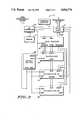
- FIG. 1is a block diagram of a frequency synthesizer with spur compensation in accordance with the present invention.
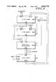
- FIG. 2is a block diagram of the divider control circuit of the frequency synthesizer of FIG. 1.
- FIG. 3is a block diagram of the offset control of FIG. 2.
- FIG. 4is a block diagram of the control logic of FIG. 2.
- FIG. 5is a block diagram of an accumulator of FIG. 2.
- FIG. 6illustrates an example of the frequency response of a two accumulator synthesizer in accordance with prior art approaches.
- FIG. 7illustrates the frequency response of the frequency synthesizer of the present invention for a selected waveform.
- a frequency synthesizer 10in accordance with the present invention, includes a reference oscillator 11.
- the output of reference oscillator 11 f ris applied to a phase detector 12 that has its output coupled, via a low pass filter 13, to a voltage controlled oscillator (VCO) 14.
- VCO 14is connected to the output 15 of the frequency synthesizer 10 and to a programmable divide by N divider 16.
- VCO 14provides the synthesizer output signal f O .
- the output of divider 16provides a divided signal f d to the phase detector 12 in a conventional manner and to a divider control circuit 17.
- Divider control circuit 17is connected to the programmable divider 16 and provides the divide or "N" information used by the divider.
- the desired output frequency f Ocannot be obtained utilizing a single divisor for the programmable divide by N divider 16. It is necessary to periodically adjust the value N in a manner such that the average output frequency is equal to the desired output frequency.
- the divider control circuit 17, as is shown in further detail in FIG. 2,is designed to provide the required N values to the programmable divider 16 while minimizing spurious signals.
- a microprocessor controller 20is used to read the data from the memory 19 and supplies the data, via a data bus, to a data register 22 which serves also as a latch.
- a frequency selector 21is coupled to the microprocessor controller 20 for choosing the synthesizer output frequency f O . In applications such as two-way radios, the frequency selector corresponds to the channel switch.
- the data register 22provides the various data outputs which have been labeled as numerator or is the k value, offset, denominator or is the D value, and N nom which is the nominal value for the N divide value.
- the numerator and offset data linesare connected to A and B inputs respectively of a multiplexer 23.
- Output data lines of multiplexer 23are connected to the input of a first accumulator 24 constituting first accumulator means. Its output, which is labeled contents, is connected to the input of a second accumulator 25 constituting second accumulator means.
- Each of the accumulators 24 and 25has a capacity input connected to the denominator output of data register 22.
- Carry outputsare provided from both accumulators 24 and 25 and are connected to two inputs of a control logic circuit 27.
- the output of control logic circuit 27is connected to the programmable divider 16.
- the N nom data line of data register 22is also connected to the control logic circuit 27.
- the microprocessor controller 20provides an output that is applied to the trigger inputs of data register 22 and an offset control circuit 26.
- the offset control circuit 26has a select output that is connected to a select input of multiplexer 23, and a reset output that is connected to reset inputs of the accumulators 24 and 25.
- Clock inputs of offset control 26, control logic 27 and accumulators 24 and 25are provided with the f d output of programmable divider 16. Alternatively, these clock signals could be provided directly by the reference oscillator 11 as f d and f r are in phase lock.
- the clock output from the programmable divider 16is coupled to a series circuit comprised of inverters 31 and 34 and a delay element 33.
- the output of inverter 31is connected to the input of inverter 34 which has its output coupled via the delay element 33 to the clock input of a flip-flop 36.
- the output of inverter 31is also coupled to a clock input of a flip-flop 35.
- a flip-flop 37has a D input coupled to V DD for maintaining the input high. Its clock input is the TRIGGER input of offset control 26.
- the Q output of flip-flop 37is coupled to the D input of flip-flop 35.
- the RESET output of offset control 26is provided by the Q output of flip-flop 35 which is also connected to the D input of flip-flop 36.
- the SELECT output of offset control 26is provided by the Q output of flip-flop 36.
- the Q bar outputs of flip-flops 35 and 36are connected to inputs of a NOR gate 38 which has its output coupled to the reset input of flip-flop 37.
- the carry output of the accumulator 24is fed to an input A of one bit adder 41, while, the carry output of the second accumulator 25 is fed to an input B of the adder 41 and to a D input of a flip-flop 42.
- the clock input of flip-flop 42is connected to the output of programmable divider 16.
- the Q bar output of flip-flop 42is coupled to input C of adder 41.
- the sum and carry outputs of adder 41are applied to the least two significant bit positions, respectively, of the word B input of an adder 43.
- the N nom data stored in data register 22is coupled to the word A input of adder 43.
- FIG. 5an accumulator of the type used for accumulators 24 and 25 of FIG. 2, is illustrated in detail.
- Two adders 45 and 46, 2-to-1 multiplexer 47 and latch 48are connected serially through their respective inputs and outputs.
- the RESET output of offset control circuit 26is coupled to the reset input of the latch 48 for initializing the output of the latch.
- the adder 45sums the value at its input A, which is the accumulator input, with the output of latch 48 and applies the result to input A of the second adder 46, and also to the IN 0 input of 2-to-1 multiplexer 47.
- a value corresponding to the two's compliment of the capacityis applied at input B of adder 46, which is the accumulators CAPACITY input.
- the capacityis defined as being the minimum value which causes the accumulator to generate a carry signal.
- the sum from adder 46is applied at the IN1 input of the multiplexer 47.
- the carry outputs of the adders 45 and 46are applied to inputs of an OR gate 49.
- the output of the OR gate 49is brought out as the CARRY output of the accumulator.
- the output of OR gate 49is coupled to the select input of multiplexer 47, to determine whether IN 0 or IN 1 of multiplexer 47 will be fed into the input of latch 48.
- the output of multiplexer 47is the CONTENTS output of the accumulator.
- the clock input to latch 48which is accumulator clock input, is pulsed to transfer the value from the input to the output of the latch.
- the divider control circuit 17 of the preferred embodimentutilizes a multiplexer and offset control to introduce an offset value in accumulators, for improved fractional N-synthesis.
- Various other circuit implementationscould be utilized to obtain this desired control of the N divider including implementing the accumulators in a microprocessor.
- the input to accumulator 24 and, hence, the relationship between the two accumulators 24 and 25,is determined by which of two input words latched in the data register 22 is selected by the offset control 26 as the output of multiplexer 23 to be fed into the input of the first accumulator 24.
- the two input wordsare the numerator k for steady state conditions and the offset value which provides a predetermined starting value for the accumulators.
- the offset value for each desired frequency f Ois stored in a table in memory 19 along with the other frequency information, namely numerator, denominator and N nom values which are loaded into data register 22.
- the offset valuevaries with k, D and the required application and can be found by trial and error in actual field tests and/or preliminarily by computer simulation. To provide an offset the value can not equal zero, the numerator or the denominator. If one of these values is utilized there would be no offset.
- the offset control 26determines when a particular input word will be selected. Upon initializing the synthesizer (i.e. selecting a new output frequency f O ) the microprocessor controller 20 provides a trigger signal to stroke data into the data register 22 and clock flip-flop 37 to transfer a high Q output from its D input into D input of flip-flop 35. When the inverted clock signal from inverter 31 clocks flip-flop 35, its high D input will be transferred to its Q output and the D input of flip-flop 36 and as a high reset signal to be applied at the reset inputs of accumulators 24 and 25. This causes the contents of both accumulators to asynchronously reset to the value applied at the input of accumulator 24 and inhibits their clock inputs. The reset is returned low.
- the Q output of flip-flop 36 of the offset control circuit 26toggles high to select the B input of the multiplexer 23. This causes the offset value to appear as the contents value of accumulator 24.
- the low Q-bar outputs of flip-flops 35 and 36reset the Q output of flip-flop 37 to low via the NOR gate 38.
- the inverted clock signalclocks flip-flop 35 to return the reset signal back to low, allowing the accumulators to increment in response to the clock signals.
- the value at the first accumulator 24 inputis stored in accumulator 24.
- the low D input of flip-flop 36is transferred as a low SELECT output.
- This low SELECT signalcauses the input A value containing the numerator to be transferred to the output of the multiplexer 23 for steady state operation.
- the microprocessor controller 20Whenever the frequency selector 21 is actuated to select a new output frequency f O the microprocessor controller 20 reads the data from memory 19 for the selected frequency causing the data to clocked into data register 22. The microprocessor controller 20 triggers the data register and offset control to cause the offset value to be applied to the first and second accumulators 24 and 25. The multiplexer 23 is then switched to provide the numerator value to the input of accumulator 24 where it is summed with the previously loaded offset value. For each clock pulse from the f d signal the numerator value is again summed with the contents of accumulator 24. Similarly, the output of accumator 1 is summed in accumator 25.
- the first accumulator 24has a capacity of D as does the second accumulator 25. For each clock cycle, an input is added to the contents of the first accumulator 24. Contents from the first accumulator 24 are added to the contents of the second accumulator 25. For each clock cycle the accumulator capacity D is reached, that particular accumulator overflows and a carry value of one is generated. Otherwise, a carry value of zero is generated.
- the net effect over D cycles of the reference clockis that k carry pulses are produced by the first accumulator 24.
- Accumulator 25has no effect on the average value of N since the counts are always added and subtracted in pairs by the second accumulator 25.
- the average value of the programmable divisorthen has a whole part equal to the programmed value N and a fractional part equal to k/D.
- the circuit of the preferred embodimentutilizes the multiplexer 23 to load the offset into the first accumulator 24, other variations, such as loading the offset into the second accumulator 25 or loading the offset value directly to the input of the first accumulator 24 or second accumulator 25 for one or more clock cycles are possible.
- variable capacity accumulators 24 and 25permits the channel spacing of the synthesizer 10 to be easily changed. For example, to permit either 5 or 61/4 kHz channel spacing, the accumulators need only have sufficient capacity (i.e. length or number of bits) to support 5 kHz spacing. If fixed length accumulators were used, they would have to support 11/4 kHz spacing to synthesize both 5 and 61/4 kHz channels. This would require much larger accumulators than two programmable accumulators 24 and 25.
Landscapes
- Stabilization Of Oscillater, Synchronisation, Frequency Synthesizers (AREA)
- Synchronisation In Digital Transmission Systems (AREA)
- Mobile Radio Communication Systems (AREA)
Abstract
Description
Claims (6)
Priority Applications (30)
| Application Number | Priority Date | Filing Date | Title |
|---|---|---|---|
| US07/202,065US4816774A (en) | 1988-06-03 | 1988-06-03 | Frequency synthesizer with spur compensation |
| US07/329,239US4918403A (en) | 1988-06-03 | 1989-03-27 | Frequency synthesizer with spur compensation |
| MYPI89000382AMY103991A (en) | 1988-06-03 | 1989-03-27 | Frequency synthesizer with spur compensation. |
| CA000594826ACA1315363C (en) | 1988-06-03 | 1989-03-28 | Frequency synthesizer with spur compensation |
| IL89833AIL89833A (en) | 1988-06-03 | 1989-04-04 | Frequency synthesizer |
| PH38460APH26602A (en) | 1988-06-03 | 1989-04-07 | Frequency synthesizer with spur compensation |
| AR89313782AAR246138A1 (en) | 1988-06-03 | 1989-04-27 | Frequency synthesizer with spur compensation |
| JP1506310AJP2645525B2 (en) | 1988-06-03 | 1989-05-11 | Frequency synthesizer with spurious compensation |
| SU894831950ARU2085031C1 (en) | 1988-06-03 | 1989-05-11 | Frequency synthesizer for producing synthesized output frequency |
| PCT/US1989/002040WO1989012362A1 (en) | 1988-06-03 | 1989-05-11 | Frequency synthesizer with spur compensation |
| HU407/89AHU217392B (en) | 1988-06-03 | 1989-05-11 | Frequency synthesizer and method for producing synthesized output frequency |
| BR898907360ABR8907360A (en) | 1988-06-03 | 1989-05-11 | FREQUENCY SYNTHESIZER AND PROCESS OF PROPECTING A SYNTHESIZED OUTPUT FREQUENCY |
| KR1019900700198AKR0164592B1 (en) | 1988-06-03 | 1989-05-11 | Frequency synthesizer and how to provide synthesized output frequency |
| FI905875AFI905875A7 (en) | 1988-06-03 | 1989-05-11 | Frequency synthesizer with interference compensation |
| AU37410/89AAU620110B2 (en) | 1988-06-03 | 1989-05-11 | Frequency synthesizer with spur compensation |
| EP89108738AEP0344509B1 (en) | 1988-06-03 | 1989-05-16 | Frequency synthesizer with spur compensation |
| ES89108738TES2051321T3 (en) | 1988-06-03 | 1989-05-16 | FREQUENCY SYNTHESIZER WITH PARASITE FREQUENCY COMPENSATION. |
| AT8989108738TATE104815T1 (en) | 1988-06-03 | 1989-05-16 | FREQUENCY SYNTHESIZER WITH COMPENSATION OF NOISE SIGNALS. |
| DE68914717TDE68914717T2 (en) | 1988-06-03 | 1989-05-16 | Frequency synthesizer with interference signal compensation. |
| PT90641APT90641B (en) | 1988-06-03 | 1989-05-23 | FREQUENCY SYNTHESIZER WITH STIMULUS COMPENSATION |
| MX16151AMX164871B (en) | 1988-06-03 | 1989-05-23 | FREQUENCY SYNTHESIZER WITH BRANCH COMPENSATION |
| YU112489AYU47487B (en) | 1988-06-03 | 1989-06-01 | REMOVAL-N-FREQUENCY SYNTHETIZER |
| EG26689AEG19069A (en) | 1988-06-03 | 1989-06-01 | Frequency synthesizer with spur compensation |
| TR89/0466ATR24163A (en) | 1988-06-03 | 1989-06-02 | PARASITE COMPENSATION FREQUENCY SINTESAYER |
| CN89103671ACN1016660B (en) | 1988-06-03 | 1989-06-02 | Frequency synthesizer with excitation compensation |
| DD89329216ADD283880A5 (en) | 1988-06-03 | 1989-06-02 | FREQUENCY SYNTHESIZER WITH STOER COMPENSATION |
| IE175289AIE65955B1 (en) | 1988-06-03 | 1989-06-12 | Frequency synthesizer with spur compensation |
| NO905095ANO905095D0 (en) | 1988-06-03 | 1990-11-26 | A frequency synthesizer. |
| DK281690ADK281690D0 (en) | 1988-06-03 | 1990-11-27 | FREQUENCY SYNTHESIS WITH PARASIT Vibration Compensation |
| HK72097AHK72097A (en) | 1988-06-03 | 1997-05-29 | Frequency synthesizer with spur compensation |
Applications Claiming Priority (1)
| Application Number | Priority Date | Filing Date | Title |
|---|---|---|---|
| US07/202,065US4816774A (en) | 1988-06-03 | 1988-06-03 | Frequency synthesizer with spur compensation |
Related Child Applications (1)
| Application Number | Title | Priority Date | Filing Date |
|---|---|---|---|
| US07/329,239ContinuationUS4918403A (en) | 1988-06-03 | 1989-03-27 | Frequency synthesizer with spur compensation |
Publications (1)
| Publication Number | Publication Date |
|---|---|
| US4816774Atrue US4816774A (en) | 1989-03-28 |
Family
ID=22748377
Family Applications (1)
| Application Number | Title | Priority Date | Filing Date |
|---|---|---|---|
| US07/202,065Expired - LifetimeUS4816774A (en) | 1988-06-03 | 1988-06-03 | Frequency synthesizer with spur compensation |
Country Status (28)
| Country | Link |
|---|---|
| US (1) | US4816774A (en) |
| EP (1) | EP0344509B1 (en) |
| JP (1) | JP2645525B2 (en) |
| KR (1) | KR0164592B1 (en) |
| CN (1) | CN1016660B (en) |
| AR (1) | AR246138A1 (en) |
| AT (1) | ATE104815T1 (en) |
| AU (1) | AU620110B2 (en) |
| BR (1) | BR8907360A (en) |
| CA (1) | CA1315363C (en) |
| DD (1) | DD283880A5 (en) |
| DE (1) | DE68914717T2 (en) |
| DK (1) | DK281690D0 (en) |
| EG (1) | EG19069A (en) |
| ES (1) | ES2051321T3 (en) |
| FI (1) | FI905875A7 (en) |
| HK (1) | HK72097A (en) |
| HU (1) | HU217392B (en) |
| IE (1) | IE65955B1 (en) |
| IL (1) | IL89833A (en) |
| MX (1) | MX164871B (en) |
| MY (1) | MY103991A (en) |
| PH (1) | PH26602A (en) |
| PT (1) | PT90641B (en) |
| RU (1) | RU2085031C1 (en) |
| TR (1) | TR24163A (en) |
| WO (1) | WO1989012362A1 (en) |
| YU (1) | YU47487B (en) |
Cited By (47)
| Publication number | Priority date | Publication date | Assignee | Title |
|---|---|---|---|---|
| US4918403A (en)* | 1988-06-03 | 1990-04-17 | Motorola, Inc. | Frequency synthesizer with spur compensation |
| US4975650A (en)* | 1989-07-24 | 1990-12-04 | Motorola, Inc. | Phase detector |
| US5021754A (en)* | 1990-07-16 | 1991-06-04 | Motorola, Inc. | Fractional-N synthesizer having modulation spur compensation |
| US5038117A (en)* | 1990-01-23 | 1991-08-06 | Hewlett-Packard Company | Multiple-modulator fractional-N divider |
| US5055800A (en)* | 1990-04-30 | 1991-10-08 | Motorola, Inc. | Fractional n/m synthesis |
| US5055802A (en)* | 1990-04-30 | 1991-10-08 | Motorola, Inc. | Multiaccumulator sigma-delta fractional-n synthesis |
| US5065408A (en)* | 1990-04-26 | 1991-11-12 | Motorola, Inc. | Fractional-division synthesizer for a voice/data communications systems |
| US5070310A (en)* | 1990-08-31 | 1991-12-03 | Motorola, Inc. | Multiple latched accumulator fractional N synthesis |
| US5093632A (en)* | 1990-08-31 | 1992-03-03 | Motorola, Inc. | Latched accumulator fractional n synthesis with residual error reduction |
| US5166642A (en)* | 1992-02-18 | 1992-11-24 | Motorola, Inc. | Multiple accumulator fractional N synthesis with series recombination |
| US5194829A (en)* | 1990-09-08 | 1993-03-16 | U.S. Philips Corporation | Radio set with easily selected oscillator frequency |
| US5212833A (en)* | 1989-09-13 | 1993-05-18 | Sony Corporation | Microcomputer controlled synthesizer-type radio receiver |
| US5224132A (en)* | 1992-01-17 | 1993-06-29 | Sciteq Electronics, Inc. | Programmable fractional-n frequency synthesizer |
| US5257294A (en)* | 1990-11-13 | 1993-10-26 | National Semiconductor Corporation | Phase-locked loop circuit and method |
| EP0581572A1 (en)* | 1992-07-31 | 1994-02-02 | Nokia Mobile Phones Ltd. | Method and system for frequency converting |
| US5305362A (en)* | 1992-12-10 | 1994-04-19 | Hewlett-Packard Company | Spur reduction for multiple modulator based synthesis |
| US5331293A (en)* | 1992-09-02 | 1994-07-19 | Motorola, Inc. | Compensated digital frequency synthesizer |
| US5337024A (en)* | 1993-06-22 | 1994-08-09 | Rockwell International Corporation | Phase locked loop frequency modulator using fractional division |
| US5371765A (en)* | 1992-07-10 | 1994-12-06 | Hewlett-Packard Company | Binary phase accumulator for decimal frequency synthesis |
| US5469479A (en)* | 1992-02-27 | 1995-11-21 | Texas Instruments Incorporated | Digital chirp synthesizer |
| US5495206A (en)* | 1993-10-29 | 1996-02-27 | Motorola, Inc. | Fractional N frequency synthesis with residual error correction and method thereof |
| US5517534A (en)* | 1992-06-08 | 1996-05-14 | Tektronix, Inc. | Phase locked loop with reduced phase noise |
| DE4291263C2 (en)* | 1991-05-03 | 1996-11-21 | Motorola Inc | Digital frequency synthesizer and digital frequency control method for modulating an input signal on a carrier signal |
| WO1997010647A1 (en)* | 1995-09-16 | 1997-03-20 | Temic Telefunken Microelectronic Gmbh | Transmission process in which a conversion oscillator signal is synthesised by means of a fractional n-phase-shift control loop |
| WO1997028606A1 (en)* | 1996-01-30 | 1997-08-07 | Motorola Inc. | Method and apparatus for controlling a fractional-n synthesizer in a time division multiple access system |
| GB2319371A (en)* | 1990-08-21 | 1998-05-20 | Thomson Trt Defence | Frequency synthesizer with a phase-locked loop with multiple fractional division |
| US5777521A (en)* | 1997-08-12 | 1998-07-07 | Motorola Inc. | Parallel accumulator fractional-n frequency synthesizer |
| US5848355A (en)* | 1993-07-07 | 1998-12-08 | Motorola, Inc. | Frequency synthesizer correction using a temperature responsive divisor control |
| US5889436A (en)* | 1996-11-01 | 1999-03-30 | National Semiconductor Corporation | Phase locked loop fractional pulse swallowing frequency synthesizer |
| US5926515A (en)* | 1995-12-26 | 1999-07-20 | Samsung Electronics Co., Ltd. | Phase locked loop for improving a phase locking time |
| JP3090790B2 (en) | 1992-08-17 | 2000-09-25 | 富士通株式会社 | Phase locked oscillator |
| US6141394A (en)* | 1997-12-22 | 2000-10-31 | Philips Electronics North America Corporation | Fractional-N frequency synthesizer with jitter compensation |
| US6219397B1 (en)* | 1998-03-20 | 2001-04-17 | Samsung Electronics Co., Ltd. | Low phase noise CMOS fractional-N frequency synthesizer for wireless communications |
| US6278333B1 (en) | 2000-02-29 | 2001-08-21 | Motorola, Inc. | Phase lock loop with dual state charge pump and method of operating the same |
| US20010036817A1 (en)* | 2000-04-17 | 2001-11-01 | Matsushita Electric Industrial Co., Ltd. | Frequency synthesizer |
| US6321074B1 (en)* | 1999-02-18 | 2001-11-20 | Itron, Inc. | Apparatus and method for reducing oscillator frequency pulling during AM modulation |
| WO2002021697A1 (en)* | 2000-09-05 | 2002-03-14 | Nokia Corporation | Fractional-n frequency synthesiser |
| US20020191727A1 (en)* | 2001-04-25 | 2002-12-19 | Texas Instruments Incorporated | Digital phase locked loop |
| US20030067405A1 (en)* | 2001-06-15 | 2003-04-10 | Keaveney Michael Francis | Variable modulus interpolator, and a variable frequency synthesiser incorporating the variable modulus interpolator |
| US6564040B1 (en)* | 1999-05-25 | 2003-05-13 | Matsushita Electric Industrial Co., Ltd. | Communication device and communication method |
| RU2208904C2 (en)* | 1997-05-07 | 2003-07-20 | Томсон-КСФ | Phase-synchronization fractional coherent- frequency synthesizer |
| US20030139169A1 (en)* | 2002-01-18 | 2003-07-24 | Gregory Arreazola | Combination insulated container and entertainment center |
| US6754474B1 (en)* | 1999-07-22 | 2004-06-22 | Alcatel | Radio transmission system |
| US20040145420A1 (en)* | 2002-11-22 | 2004-07-29 | Knierim Daniel G | Method and apparatus for the reduction of phase noise |
| US7046627B1 (en)* | 2001-02-15 | 2006-05-16 | Cisco Technology, Inc. | Method and apparatus for accumulating and distributing traffic and flow control information in a packet switching system |
| US20090081984A1 (en)* | 2007-09-25 | 2009-03-26 | Motorola, Inc. | Method and apparatus for spur reduction in a frequency synthesizer |
| EP2302781A2 (en) | 2009-09-29 | 2011-03-30 | Lenze Automation GmbH | Method for generating an output voltage with an adjustable rms value from a variable DC link voltage |
Families Citing this family (13)
| Publication number | Priority date | Publication date | Assignee | Title |
|---|---|---|---|---|
| US5307071A (en)* | 1992-04-17 | 1994-04-26 | Hughes Aircraft Company | Low noise frequency synthesizer using half integer dividers and analog gain compensation |
| JP2004104228A (en) | 2002-09-05 | 2004-04-02 | Matsushita Electric Ind Co Ltd | Signal processing device and signal processing method, delta-sigma modulation type fractional frequency division PLL frequency synthesizer, wireless communication device, delta-sigma modulation type D / A converter |
| CN1988426B (en)* | 2005-12-23 | 2010-09-01 | 中兴通讯股份有限公司 | Reference clock sending circuit and method for light repeat plate |
| RU2358384C2 (en)* | 2007-05-31 | 2009-06-10 | Государственное образовательное учреждение высшего профессионального образования Марийский государственный технический университет | Digital synthesiser of frequency and phase modulated signals |
| RU2346381C1 (en)* | 2007-06-18 | 2009-02-10 | Государственное образовательное учреждение высшего профессионального образования Марийский государственный технический университет | Digital frequency synthesiser with phase sample switching |
| RU2419201C1 (en)* | 2010-02-24 | 2011-05-20 | Открытое акционерное общество "Концерн "Созвездие" | Adaptive frequency synthesiser with switching of elements of ring of phase automatic control |
| RU2434322C1 (en)* | 2010-06-23 | 2011-11-20 | Открытое акционерное общество "Концерн "Созвездие" | Frequency synthesizer |
| DE102011053121B4 (en) | 2011-08-30 | 2016-02-04 | Imst Gmbh | Extended delta-sigma-tau modulator circuit for a fractional-N PLL frequency synthesizer circuit |
| DE102011120769B4 (en) | 2011-12-10 | 2018-09-20 | Imst Gmbh | Synchronously modulated full-digital delta-sigma modulator circuit |
| DE202011108969U1 (en) | 2011-12-10 | 2012-02-02 | Imst Gmbh | Synchronously modulated full digital delta-sigma modulator circuit |
| RU169671U1 (en)* | 2016-11-28 | 2017-03-28 | Акционерное общество "Научно-исследовательский институт Приборостроения имени В.В. Тихомирова" | Variable Division Frequency Divider |
| RU2710280C1 (en)* | 2019-04-18 | 2019-12-25 | Федеральное государственное бюджетное образовательное учреждение высшего образования "Поволжский государственный технологический университет" | Digital computing synthesizer for double-frequency signals |
| RU2701050C1 (en)* | 2019-05-30 | 2019-09-24 | Федеральное государственное бюджетное образовательное учреждение высшего образования "Поволжский государственный технологический университет" | Digital synthesizer of phase-shift keyed signals |
Citations (13)
| Publication number | Priority date | Publication date | Assignee | Title |
|---|---|---|---|---|
| US3928813A (en)* | 1974-09-26 | 1975-12-23 | Hewlett Packard Co | Device for synthesizing frequencies which are rational multiples of a fundamental frequency |
| US3976945A (en)* | 1975-09-05 | 1976-08-24 | Hewlett-Packard Company | Frequency synthesizer |
| US4101838A (en)* | 1976-01-28 | 1978-07-18 | Tokyo Shibaura Electric Co., Ltd. | Clock pulse generating apparatus |
| US4184068A (en)* | 1977-11-14 | 1980-01-15 | Harris Corporation | Full binary programmed frequency divider |
| US4204174A (en)* | 1978-07-22 | 1980-05-20 | Racal Communications Equipment Limited | Phase locked loop variable frequency generator |
| US4231104A (en)* | 1978-04-26 | 1980-10-28 | Teradyne, Inc. | Generating timing signals |
| US4423381A (en)* | 1981-01-16 | 1983-12-27 | Cincinnati Electronics Corporation | Pulse control circuit |
| US4468797A (en)* | 1981-02-13 | 1984-08-28 | Oki Electric Industry Co., Ltd. | Swallow counters |
| US4472820A (en)* | 1981-04-06 | 1984-09-18 | Motorola, Inc. | Program swallow counting device using a single synchronous counter for frequency synthesizing |
| US4556984A (en)* | 1983-12-27 | 1985-12-03 | Motorola, Inc. | Frequency multiplier/divider apparatus and method |
| US4609881A (en)* | 1983-05-17 | 1986-09-02 | Marconi Instruments Limited | Frequency synthesizers |
| US4694475A (en)* | 1985-05-18 | 1987-09-15 | Deutsche Itt Industries Gmbh | Frequency divider circuit |
| US4714899A (en)* | 1986-09-30 | 1987-12-22 | Motorola, Inc. | Frequency synthesizer |
Family Cites Families (1)
| Publication number | Priority date | Publication date | Assignee | Title |
|---|---|---|---|---|
| EP0211921A1 (en)* | 1985-02-21 | 1987-03-04 | Plessey Overseas Limited | Improvement in or relating to synthesisers |
- 1988
- 1988-06-03USUS07/202,065patent/US4816774A/ennot_activeExpired - Lifetime
- 1989
- 1989-03-27MYMYPI89000382Apatent/MY103991A/enunknown
- 1989-03-28CACA000594826Apatent/CA1315363C/ennot_activeExpired - Lifetime
- 1989-04-04ILIL89833Apatent/IL89833A/ennot_activeIP Right Cessation
- 1989-04-07PHPH38460Apatent/PH26602A/enunknown
- 1989-04-27ARAR89313782Apatent/AR246138A1/enactive
- 1989-05-11HUHU407/89Apatent/HU217392B/ennot_activeIP Right Cessation
- 1989-05-11RUSU894831950Apatent/RU2085031C1/ennot_activeIP Right Cessation
- 1989-05-11KRKR1019900700198Apatent/KR0164592B1/ennot_activeExpired - Fee Related
- 1989-05-11FIFI905875Apatent/FI905875A7/ennot_activeIP Right Cessation
- 1989-05-11BRBR898907360Apatent/BR8907360A/ennot_activeIP Right Cessation
- 1989-05-11AUAU37410/89Apatent/AU620110B2/ennot_activeCeased
- 1989-05-11JPJP1506310Apatent/JP2645525B2/ennot_activeExpired - Fee Related
- 1989-05-11WOPCT/US1989/002040patent/WO1989012362A1/enactiveApplication Filing
- 1989-05-16ESES89108738Tpatent/ES2051321T3/ennot_activeExpired - Lifetime
- 1989-05-16DEDE68914717Tpatent/DE68914717T2/ennot_activeExpired - Fee Related
- 1989-05-16EPEP89108738Apatent/EP0344509B1/ennot_activeExpired - Lifetime
- 1989-05-16ATAT8989108738Tpatent/ATE104815T1/ennot_activeIP Right Cessation
- 1989-05-23PTPT90641Apatent/PT90641B/ennot_activeIP Right Cessation
- 1989-05-23MXMX16151Apatent/MX164871B/enunknown
- 1989-06-01EGEG26689Apatent/EG19069A/enactive
- 1989-06-01YUYU112489Apatent/YU47487B/enunknown
- 1989-06-02TRTR89/0466Apatent/TR24163A/enunknown
- 1989-06-02DDDD89329216Apatent/DD283880A5/ennot_activeIP Right Cessation
- 1989-06-02CNCN89103671Apatent/CN1016660B/ennot_activeExpired
- 1989-06-12IEIE175289Apatent/IE65955B1/ennot_activeIP Right Cessation
- 1990
- 1990-11-27DKDK281690Apatent/DK281690D0/ennot_activeApplication Discontinuation
- 1997
- 1997-05-29HKHK72097Apatent/HK72097A/ennot_activeIP Right Cessation
Patent Citations (13)
| Publication number | Priority date | Publication date | Assignee | Title |
|---|---|---|---|---|
| US3928813A (en)* | 1974-09-26 | 1975-12-23 | Hewlett Packard Co | Device for synthesizing frequencies which are rational multiples of a fundamental frequency |
| US3976945A (en)* | 1975-09-05 | 1976-08-24 | Hewlett-Packard Company | Frequency synthesizer |
| US4101838A (en)* | 1976-01-28 | 1978-07-18 | Tokyo Shibaura Electric Co., Ltd. | Clock pulse generating apparatus |
| US4184068A (en)* | 1977-11-14 | 1980-01-15 | Harris Corporation | Full binary programmed frequency divider |
| US4231104A (en)* | 1978-04-26 | 1980-10-28 | Teradyne, Inc. | Generating timing signals |
| US4204174A (en)* | 1978-07-22 | 1980-05-20 | Racal Communications Equipment Limited | Phase locked loop variable frequency generator |
| US4423381A (en)* | 1981-01-16 | 1983-12-27 | Cincinnati Electronics Corporation | Pulse control circuit |
| US4468797A (en)* | 1981-02-13 | 1984-08-28 | Oki Electric Industry Co., Ltd. | Swallow counters |
| US4472820A (en)* | 1981-04-06 | 1984-09-18 | Motorola, Inc. | Program swallow counting device using a single synchronous counter for frequency synthesizing |
| US4609881A (en)* | 1983-05-17 | 1986-09-02 | Marconi Instruments Limited | Frequency synthesizers |
| US4556984A (en)* | 1983-12-27 | 1985-12-03 | Motorola, Inc. | Frequency multiplier/divider apparatus and method |
| US4694475A (en)* | 1985-05-18 | 1987-09-15 | Deutsche Itt Industries Gmbh | Frequency divider circuit |
| US4714899A (en)* | 1986-09-30 | 1987-12-22 | Motorola, Inc. | Frequency synthesizer |
Non-Patent Citations (2)
| Title |
|---|
| "Esscirc 82", Eighth European Solid State Circuits Conference, Brussells, Sep. 22-24, 1982, pp. 145 to 148. |
| Esscirc 82 , Eighth European Solid State Circuits Conference, Brussells, Sep. 22 24, 1982, pp. 145 to 148.* |
Cited By (88)
| Publication number | Priority date | Publication date | Assignee | Title |
|---|---|---|---|---|
| US4918403A (en)* | 1988-06-03 | 1990-04-17 | Motorola, Inc. | Frequency synthesizer with spur compensation |
| US4975650A (en)* | 1989-07-24 | 1990-12-04 | Motorola, Inc. | Phase detector |
| WO1991002405A1 (en)* | 1989-07-24 | 1991-02-21 | Motorola, Inc. | Phase detector |
| EP0483260A4 (en)* | 1989-07-24 | 1992-10-07 | Motorola, Inc. | Phase detector |
| US5212833A (en)* | 1989-09-13 | 1993-05-18 | Sony Corporation | Microcomputer controlled synthesizer-type radio receiver |
| US5038117A (en)* | 1990-01-23 | 1991-08-06 | Hewlett-Packard Company | Multiple-modulator fractional-N divider |
| JP3082860B2 (en) | 1990-04-26 | 2000-08-28 | モトローラ・インコーポレイテッド | Fractional divider synthesizer for voice / data communication systems |
| US5065408A (en)* | 1990-04-26 | 1991-11-12 | Motorola, Inc. | Fractional-division synthesizer for a voice/data communications systems |
| EP0479969A4 (en)* | 1990-04-26 | 1993-09-29 | Motorola, Inc. | Fractional-division synthesizer for a voice/data communications system |
| JP2756728B2 (en) | 1990-04-30 | 1998-05-25 | モトローラ・インコーポレーテッド | Synthesis of multistage accumulator sigma-delta fraction N |
| US5055802A (en)* | 1990-04-30 | 1991-10-08 | Motorola, Inc. | Multiaccumulator sigma-delta fractional-n synthesis |
| US5055800A (en)* | 1990-04-30 | 1991-10-08 | Motorola, Inc. | Fractional n/m synthesis |
| EP0480012A4 (en)* | 1990-04-30 | 1992-10-07 | Motorola, Inc. | Multiaccumulator sigma-delta fractional-n synthesis |
| WO1992002077A1 (en)* | 1990-07-16 | 1992-02-06 | Motorola, Inc. | Fractional-n synthesizer having modulation spur compensation |
| US5021754A (en)* | 1990-07-16 | 1991-06-04 | Motorola, Inc. | Fractional-N synthesizer having modulation spur compensation |
| GB2319371B (en)* | 1990-08-21 | 1998-09-09 | Thomson Trt Defence | Frequency synthesizer with a phase-locked loop with multiple fractional division |
| GB2319371A (en)* | 1990-08-21 | 1998-05-20 | Thomson Trt Defence | Frequency synthesizer with a phase-locked loop with multiple fractional division |
| AT402247B (en)* | 1990-08-31 | 1997-03-25 | Motorola Inc | BREAKAGE-N-SYNTHESIS WITH SEVERAL LOCKED STORAGE WORKS |
| WO1992004767A1 (en)* | 1990-08-31 | 1992-03-19 | Motorola, Inc. | Latched accumulator fractional n synthesis with residual error reduction |
| AU632243B2 (en)* | 1990-08-31 | 1992-12-17 | Motorola, Inc. | Multiple latched accumulator fractional n synthesis |
| DE4192071C2 (en)* | 1990-08-31 | 1996-02-22 | Motorola Inc | Device for frequency synthesis using non-integer frequency division ratios |
| US5093632A (en)* | 1990-08-31 | 1992-03-03 | Motorola, Inc. | Latched accumulator fractional n synthesis with residual error reduction |
| DE4192081C2 (en)* | 1990-08-31 | 1996-02-01 | Motorola Inc | Device for frequency synthesis using non-integer frequency division ratios |
| JP2844389B2 (en) | 1990-08-31 | 1999-01-06 | モトローラ・インコーポレーテッド | Synthesis of multistage latch accumulator fraction N |
| US5070310A (en)* | 1990-08-31 | 1991-12-03 | Motorola, Inc. | Multiple latched accumulator fractional N synthesis |
| ES2088714A1 (en)* | 1990-08-31 | 1996-08-16 | Motorola Inc | Multiple latched accumulator fractional n synthesis |
| GB2255680A (en)* | 1990-08-31 | 1992-11-11 | Motorola Inc | Multiple latched accumulator fractional n synthesis |
| AU646304B2 (en)* | 1990-08-31 | 1994-02-17 | Motorola, Inc. | Latched accumulator fractional N synthesizer |
| FR2666464A1 (en)* | 1990-08-31 | 1992-03-06 | Motorola Inc | METHOD AND APPARATUS FOR FREQUENCY SYNTHESIS OF FRACTIONAL N - FREQUENCY WITH TEMPORARY MEMORIZED MULTI - STORAGE BATTERIES AND APPLICATION TO RADIO. |
| WO1992004766A1 (en)* | 1990-08-31 | 1992-03-19 | Motorola, Inc. | Multiple latched accumulator fractional n synthesis |
| AT402246B (en)* | 1990-08-31 | 1997-03-25 | Motorola Inc | BREAKAGE-N-SYNTHESIS WITH LOCKED STORAGE WORKS AND WITH REDUCTION OF THE RESIDUAL ERROR |
| GB2255680B (en)* | 1990-08-31 | 1994-08-03 | Motorola Inc | Multiple latched accumulator fractional-N synthesis |
| GB2253752A (en)* | 1990-08-31 | 1992-09-16 | Motorola Inc | Latched accumulator fractional n synthesis with residual error reduction |
| GB2253752B (en)* | 1990-08-31 | 1994-11-23 | Motorola Inc | Latched accumulator fractional-n synthesis with reduced residual error |
| ES2088715A1 (en)* | 1990-08-31 | 1996-08-16 | Motorola Inc | FRACTIONAL-N SYNTHESIS OF ENGAGED ACCUMULATORS WITH REDUCTION OF RESIDUAL ERROR. |
| US5194829A (en)* | 1990-09-08 | 1993-03-16 | U.S. Philips Corporation | Radio set with easily selected oscillator frequency |
| US5257294A (en)* | 1990-11-13 | 1993-10-26 | National Semiconductor Corporation | Phase-locked loop circuit and method |
| DE4291263C2 (en)* | 1991-05-03 | 1996-11-21 | Motorola Inc | Digital frequency synthesizer and digital frequency control method for modulating an input signal on a carrier signal |
| US5224132A (en)* | 1992-01-17 | 1993-06-29 | Sciteq Electronics, Inc. | Programmable fractional-n frequency synthesizer |
| US5166642A (en)* | 1992-02-18 | 1992-11-24 | Motorola, Inc. | Multiple accumulator fractional N synthesis with series recombination |
| WO1993016523A1 (en)* | 1992-02-18 | 1993-08-19 | Motorola, Inc. | Multiple accumulator fractional n synthesis with series recombination |
| DE4294754C1 (en)* | 1992-02-18 | 1995-11-09 | Motorola Inc | Multiple accumulator N fractional synthesis with series recombination |
| GB2273008B (en)* | 1992-02-18 | 1995-10-25 | Motorola Inc | Multiple accumulator fractional N synthesis with series recombination |
| RU2153223C2 (en)* | 1992-02-18 | 2000-07-20 | Моторола, Инк. | Variable frequency synthesizer, method for synthesis of signal frequency using synthesizer and radio telephone |
| JP3109100B2 (en) | 1992-02-18 | 2000-11-13 | モトローラ・インコーポレイテッド | N-fractional synthesis of multiple accumulators by serial recombination |
| GB2273008A (en)* | 1992-02-18 | 1994-06-01 | Motorola Inc | Multiple accumulator fractional N synthesis with series recombination |
| US5469479A (en)* | 1992-02-27 | 1995-11-21 | Texas Instruments Incorporated | Digital chirp synthesizer |
| US5517534A (en)* | 1992-06-08 | 1996-05-14 | Tektronix, Inc. | Phase locked loop with reduced phase noise |
| US5371765A (en)* | 1992-07-10 | 1994-12-06 | Hewlett-Packard Company | Binary phase accumulator for decimal frequency synthesis |
| EP0581572A1 (en)* | 1992-07-31 | 1994-02-02 | Nokia Mobile Phones Ltd. | Method and system for frequency converting |
| JP3090790B2 (en) | 1992-08-17 | 2000-09-25 | 富士通株式会社 | Phase locked oscillator |
| US5331293A (en)* | 1992-09-02 | 1994-07-19 | Motorola, Inc. | Compensated digital frequency synthesizer |
| US5305362A (en)* | 1992-12-10 | 1994-04-19 | Hewlett-Packard Company | Spur reduction for multiple modulator based synthesis |
| US5337024A (en)* | 1993-06-22 | 1994-08-09 | Rockwell International Corporation | Phase locked loop frequency modulator using fractional division |
| US5848355A (en)* | 1993-07-07 | 1998-12-08 | Motorola, Inc. | Frequency synthesizer correction using a temperature responsive divisor control |
| US5495206A (en)* | 1993-10-29 | 1996-02-27 | Motorola, Inc. | Fractional N frequency synthesis with residual error correction and method thereof |
| WO1997010647A1 (en)* | 1995-09-16 | 1997-03-20 | Temic Telefunken Microelectronic Gmbh | Transmission process in which a conversion oscillator signal is synthesised by means of a fractional n-phase-shift control loop |
| US5926515A (en)* | 1995-12-26 | 1999-07-20 | Samsung Electronics Co., Ltd. | Phase locked loop for improving a phase locking time |
| US5684795A (en)* | 1996-01-30 | 1997-11-04 | Motorola, Inc. | Method and apparatus for controlling a fractional-N synthesizer in a time division multiple access system |
| WO1997028606A1 (en)* | 1996-01-30 | 1997-08-07 | Motorola Inc. | Method and apparatus for controlling a fractional-n synthesizer in a time division multiple access system |
| US5889436A (en)* | 1996-11-01 | 1999-03-30 | National Semiconductor Corporation | Phase locked loop fractional pulse swallowing frequency synthesizer |
| RU2208904C2 (en)* | 1997-05-07 | 2003-07-20 | Томсон-КСФ | Phase-synchronization fractional coherent- frequency synthesizer |
| US5777521A (en)* | 1997-08-12 | 1998-07-07 | Motorola Inc. | Parallel accumulator fractional-n frequency synthesizer |
| US6141394A (en)* | 1997-12-22 | 2000-10-31 | Philips Electronics North America Corporation | Fractional-N frequency synthesizer with jitter compensation |
| US6219397B1 (en)* | 1998-03-20 | 2001-04-17 | Samsung Electronics Co., Ltd. | Low phase noise CMOS fractional-N frequency synthesizer for wireless communications |
| US6321074B1 (en)* | 1999-02-18 | 2001-11-20 | Itron, Inc. | Apparatus and method for reducing oscillator frequency pulling during AM modulation |
| US6564040B1 (en)* | 1999-05-25 | 2003-05-13 | Matsushita Electric Industrial Co., Ltd. | Communication device and communication method |
| US6754474B1 (en)* | 1999-07-22 | 2004-06-22 | Alcatel | Radio transmission system |
| US6278333B1 (en) | 2000-02-29 | 2001-08-21 | Motorola, Inc. | Phase lock loop with dual state charge pump and method of operating the same |
| US6728526B2 (en)* | 2000-04-17 | 2004-04-27 | Matsushita Electric Industrial Co., Ltd. | Fractional-N frequency synthesizer with multiple clocks having different timings |
| US20010036817A1 (en)* | 2000-04-17 | 2001-11-01 | Matsushita Electric Industrial Co., Ltd. | Frequency synthesizer |
| WO2002021697A1 (en)* | 2000-09-05 | 2002-03-14 | Nokia Corporation | Fractional-n frequency synthesiser |
| US7046627B1 (en)* | 2001-02-15 | 2006-05-16 | Cisco Technology, Inc. | Method and apparatus for accumulating and distributing traffic and flow control information in a packet switching system |
| US20020191727A1 (en)* | 2001-04-25 | 2002-12-19 | Texas Instruments Incorporated | Digital phase locked loop |
| US8385476B2 (en)* | 2001-04-25 | 2013-02-26 | Texas Instruments Incorporated | Digital phase locked loop |
| US8742808B2 (en) | 2001-04-25 | 2014-06-03 | Texas Instruments Incorporated | Digital phase locked loop |
| US9893735B2 (en) | 2001-04-25 | 2018-02-13 | Texas Instruments Incorporated | Digital phase locked loop |
| US20030067405A1 (en)* | 2001-06-15 | 2003-04-10 | Keaveney Michael Francis | Variable modulus interpolator, and a variable frequency synthesiser incorporating the variable modulus interpolator |
| US7006024B2 (en)* | 2001-06-15 | 2006-02-28 | Analog Devices, Inc. | Variable modulus interpolator, and a variable frequency synthesiser incorporating the variable modulus interpolator |
| US20050231408A1 (en)* | 2001-06-15 | 2005-10-20 | Keaveney Michael F | Variable modulus interpolator, and a variable frequency synthesiser incorporating the variable modulus interpolator |
| US6927716B2 (en)* | 2001-06-15 | 2005-08-09 | Analog Devices, Inc. | Variable modulus interpolator, and a variable frequency synthesizer incorporating the variable modulus interpolator |
| US20030139169A1 (en)* | 2002-01-18 | 2003-07-24 | Gregory Arreazola | Combination insulated container and entertainment center |
| US20040145420A1 (en)* | 2002-11-22 | 2004-07-29 | Knierim Daniel G | Method and apparatus for the reduction of phase noise |
| US7071787B2 (en)* | 2002-11-22 | 2006-07-04 | Tektronix, Inc. | Method and apparatus for the reduction of phase noise |
| US7929929B2 (en) | 2007-09-25 | 2011-04-19 | Motorola Solutions, Inc. | Method and apparatus for spur reduction in a frequency synthesizer |
| US20090081984A1 (en)* | 2007-09-25 | 2009-03-26 | Motorola, Inc. | Method and apparatus for spur reduction in a frequency synthesizer |
| DE102009048550A1 (en) | 2009-09-29 | 2011-04-07 | Lenze Automation Gmbh | Method for generating an output voltage |
| EP2302781A2 (en) | 2009-09-29 | 2011-03-30 | Lenze Automation GmbH | Method for generating an output voltage with an adjustable rms value from a variable DC link voltage |
Also Published As
Similar Documents
| Publication | Publication Date | Title |
|---|---|---|
| US4816774A (en) | Frequency synthesizer with spur compensation | |
| US4918403A (en) | Frequency synthesizer with spur compensation | |
| US5065408A (en) | Fractional-division synthesizer for a voice/data communications systems | |
| EP1330035B1 (en) | Fractional-N frequency synthesizer with sine wave generator | |
| US4609881A (en) | Frequency synthesizers | |
| US6927716B2 (en) | Variable modulus interpolator, and a variable frequency synthesizer incorporating the variable modulus interpolator | |
| US4998072A (en) | High resolution direct digital synthesizer | |
| US6693468B2 (en) | Fractional-N synthesizer with improved noise performance | |
| JP2004519917A (en) | Σ-ΔN frequency divider with improved noise and spur performance | |
| JPH0439690B2 (en) | ||
| US6779010B2 (en) | Accumulator with programmable full-scale range | |
| US5305362A (en) | Spur reduction for multiple modulator based synthesis | |
| US4556984A (en) | Frequency multiplier/divider apparatus and method | |
| US4145667A (en) | Phase locked loop frequency synthesizer using digital modulo arithmetic | |
| US6316982B1 (en) | Digital clock with controllable phase skew | |
| JPH05506338A (en) | frequency synthesizer | |
| US4514696A (en) | Numerically controlled oscillator | |
| KR100795173B1 (en) | Frequency synthesizer | |
| SU1621170A2 (en) | Direct-action digital frequency synthesizer | |
| KR0138024B1 (en) | I.d.e interface apparatus |
Legal Events
| Date | Code | Title | Description |
|---|---|---|---|
| AS | Assignment | Owner name:MOTOROLA, INC., SCHAUMBURG, ILLINOIS, A CORP. OF D Free format text:ASSIGNMENT OF ASSIGNORS INTEREST.;ASSIGNOR:MARTIN, FREDERICK L.;REEL/FRAME:004887/0036 Effective date:19880531 Owner name:MOTOROLA, INC., A CORP. OF DE.,ILLINOIS Free format text:ASSIGNMENT OF ASSIGNORS INTEREST;ASSIGNOR:MARTIN, FREDERICK L.;REEL/FRAME:004887/0036 Effective date:19880531 | |
| STCF | Information on status: patent grant | Free format text:PATENTED CASE | |
| FPAY | Fee payment | Year of fee payment:4 | |
| FPAY | Fee payment | Year of fee payment:8 | |
| FPAY | Fee payment | Year of fee payment:12 | |
| AS | Assignment | Owner name:WI-LAN INC., CANADA Free format text:ASSIGNMENT OF ASSIGNORS INTEREST;ASSIGNOR:MOTOROLA SOLUTIONS, INC.;REEL/FRAME:026889/0573 Effective date:20100126 | |
| AS | Assignment | Owner name:QUARTERHILL INC., CANADA Free format text:MERGER AND CHANGE OF NAME;ASSIGNORS:WI-LAN INC.;QUARTERHILL INC.;REEL/FRAME:042914/0596 Effective date:20170601 | |
| AS | Assignment | Owner name:WI-LAN INC., CANADA Free format text:ASSIGNMENT OF ASSIGNORS INTEREST;ASSIGNOR:QUARTERHILL INC.;REEL/FRAME:043168/0323 Effective date:20170601 |