US4816670A - Optical measuring head - Google Patents
Optical measuring headDownload PDFInfo
- Publication number
- US4816670A US4816670AUS07/098,332US9833287AUS4816670AUS 4816670 AUS4816670 AUS 4816670AUS 9833287 AUS9833287 AUS 9833287AUS 4816670 AUS4816670 AUS 4816670A
- Authority
- US
- United States
- Prior art keywords
- light
- light receiving
- receiving fiber
- measuring head
- cylindrical portion
- Prior art date
- Legal status (The legal status is an assumption and is not a legal conclusion. Google has not performed a legal analysis and makes no representation as to the accuracy of the status listed.)
- Expired - Fee Related
Links
Images

Classifications
- G—PHYSICS
- G01—MEASURING; TESTING
- G01N—INVESTIGATING OR ANALYSING MATERIALS BY DETERMINING THEIR CHEMICAL OR PHYSICAL PROPERTIES
- G01N21/00—Investigating or analysing materials by the use of optical means, i.e. using sub-millimetre waves, infrared, visible or ultraviolet light
- G01N21/17—Systems in which incident light is modified in accordance with the properties of the material investigated
- G01N21/47—Scattering, i.e. diffuse reflection
- G01N21/4738—Diffuse reflection, e.g. also for testing fluids, fibrous materials
- G01N21/474—Details of optical heads therefor, e.g. using optical fibres
Definitions
- the present inventiongenerally relates to a measuring instrument and more particularly, to an optical measuring head which employs optical fibers.
- an optical measuring heademploying optical fibers for examination, for example, of a blood specimen 8 as shown in FIG. 4 or 7.
- the known optical measuring head shown in FIG. 4includes light projecting fibers 2 axially disposed side by side in a cable, and a light receiving fiber 4 also axially provided within the same cable as illustrated, and is so arranged that reflection of light projected onto the blood specimen 8 which is an object to be measured, from the light projecting fibers 2 is received by the light receiving fiber 4 so as to be transmitted to a measuring device (not shown) for measuring the nature or characteristics of the blood specimen 8 by the amount of the reflected light.
- the known optical measuring head as described abovehas such a problem that it is difficult to effect an accurate examination, since the amount of the reflected light tends to vary upon variation of the distance between said measuring head and the blood specimen 8.
- the blood specimen 8is composed of a transparent protective layer 9, a reacting layer (colored layer) 10, a white reflecting layer 11 and a developing layer 12 disposed one upon another from the side of the measuring head as shown in FIG. 6, and is so arranged that light by the light projecting fibers 2 is led from the transparent protective layer 9 to the reacting layer 10, while the light which has passed through the reacting layer 10 (i.e., the light except for that absorbed by the reacting layer 10) is reflected by the white reflecting layer 11 so as to be incident upon the light receiving fiber 4 through said reacting layer 10 and transparent protective layer 9, whereby the amount of the incident light (indicated by an arrow A in FIG. 6) is to be measured.
- FIG. 7another conventional optical measuring head shown in FIG. 7 includes the light projecting fibers 2 and light receiving fiber 4 provided in the similar manner as in the measuring head of FIG. 4, and a convex lens 13 disposed in front of the light receiving fiber 4 so as to receive the reflected light from the blood specimen 8 in a converged state, and further, a casing 15 having a transparent glass plate 14 at its forward end and applied over the outer periphery of the head as indicated by two-dotted chain lines depending on necessity.
- an essential object of the present inventionis to provide an improved optical measuring head which is capable of accurately measuring characteristics of an object to be measured, by receiving only reflected light from the object and without being affected by the variation of the distance with respect to said object.
- Another object of the present inventionis to provide an optical measuring head of the above described type which is simple in construction and stable in functioning, and readily manufactured at low cost.
- an optical measuring headwhich includes a cylindrical portion having a circular cross section, a plurality of light projecting fibers axially disposed in the cylindrical portion through a predetermined distance, a light receiving fiber provided along an axis of the cylindrical portion, and a convex lens formed, at its outer peripheral portion, with a light receiving face for receiving the light from the light projecting fibers and directing the light through the lens so that the light will be incident upon the surface of the lens adjacent an object to be measured, at an angle smaller than a critical angle so the light will not be reflected by the surface, and disposed at a position coaxial with the light receiving; fiber for focusing on a forward end face of the light receiving fiber.
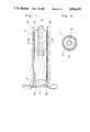
- FIG. 1is a fragmentary longitudinal sectional view of an optical measuring head according to one preferred embodiment of the present invention
- FIG. 2is a cross section taken along the line II--II in FIG. 1;
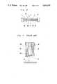
- FIG. 3is a diagram showing relation between an incident angle upon a convex lens and incident light upon a light receiving fiber
- FIG. 4is a fragmentary longitudinal sectional view of a conventional optical measuring head (already referred to);
- FIG. 5is a cross section taken along the line V--V in FIG. 4;
- FIG. 6is a side sectional view showing one example of construction of a blood specimen (already referred to).
- FIG. 7is a fragmentary longitudinal sectional view of another conventional optical measuring head (already referred to).
- an optical measuring headwhich generally includes a cylindrical portion 1 having a circular cross section, a plurality of light projecting fibers 2 axially disposed in said cylindrical portion 1 with a predetermined distance therebetween, a light receiving fiber 4 fixed at the axis of said cylindrical portion 1 through a holding member 3, with undulation having a saw-tooth cross section being formed on the inner-surface of the cylindrical portion 1 to prevent light reflection towards the side of the light receiving fiber 4, and a convex lens 6 formed, at its outer peripheral portion, with a light receiving face 5 for receiving the light from the light projecting fibers 2 and directing the light through the lens so as to be incident upon the surface 7 of the lens adjacent an object 8 to be measured, at an angle smaller than a critical angle whereby the light will not be reflected by the surface 7, and disposed at a position coaxial with the light receiving fiber 4 for focusing the light reflected from the object on a forward end face of said light
- the under surface 7 of the convex lens 6 facing the object 8 to be measuredis a flat surface, and its upper surface at the opposite side is formed into a curved surface, while the light receiving face 5 thereof is formed into a tapered surface having a straight line in cross section, whereby the light emitted from the light projecting fibers 2 goes through the convex lens 6 without being totally reflected at the under surface 7, and returns to the light receiving fiber 4 after reflection by the object 8 to be measured, for example, the blood specimen located under the measuring head.
- the predetermined distance ris assumed to be a radius of the light receiving fiber 4.
- fFcorresponds to the forward end face of the light receiving fiber 4, and as in the light represented by a two-dotted chain line C, in the case where the incident angle ⁇ with respect to the convex lens 6 is in the relation ⁇ > ⁇ 0 , the light transmitted through the convex lens 6 is deviated from the portion Ff so as not to be incident upon the light receiving fiber 4, while when the relation is ⁇ 0 as shown by a one-dotted chain line D, the light transmitted through the convex lens 6 passes through the portion fF so as to be incident upon the light receiving fiber 4.
- the amount of light in a predetermined solid angleis reduced in inverse proportion to the square of a distance between said point and the light source, while the area of a plane illuminated by the light source is directly proportional to the square of the above distance, and therefore, the sum of the amount of light within the predetermined solid angle at all points of the irradiated plane becomes constant.
- the amount of light entering the light receiving fiber 4becomes constant irrespective of the distance between the object to be measured and the convex lens 6. Moreover, in the case where the object to be measured is of the blood specimen 8, the light emitted from the light projecting fibers 2 and reflected by the transparent protective layer 9 without reaching the reacting layer 10 and the white reflecting layer 11, protrudes from said predetermined solid angle, without entering said light receiving fiber 4, and thus, the result of the measurement is not affected thereby.
- the object to be measuredis described as the blood specimen, the present invention is not limited in its application to the measurement of the nature of such blood specimen alone, but may be applied to measurements of characteristics of various other objects.
- the optical measuring headis constituted by the cylindrical portion having a circular cross section, the plurality of light projecting fibers axially disposed in the cylindrical portion through a predetermined distance, the light receiving fiber provided along the axis of the cylindrical portion, and the convex lens formed, at its outer peripheral portion, with the light receiving face for receiving the light from the light projecting fibers and directing the light through the lens so that the light will be incident upon the surface of the lens adjacent the object to be measured, at an angle smaller than the critical angle, and disposed at a position coaxial with the light receiving fiber for focusing on the forward end face of the light receiving fiber.
- the optical measuring headeven when the distance between the object to be measured and the convex lens, i.e., the optical measuring head, is varied due to, for example, errors in setting the object to be measured, etc., the characteristics of the object to be measured (e.g., besides the state of the blood specimen as described so far, surface conditions such as density, tone of shade, undulation, presence of foreign matter, etc. of various other objects) may be measured without being affected by such variation.
- the object to be measuredis, for example, of the blood specimen as described earlier, since it is possible to prevent the reflected light by the transparent protective layer from entering the light receiving fiber, a still more accurate measurement can be effected in cooperation with the earlier-mentioned advantage of not being affected by the distance.
Landscapes
- Physics & Mathematics (AREA)
- Health & Medical Sciences (AREA)
- Life Sciences & Earth Sciences (AREA)
- Chemical & Material Sciences (AREA)
- Analytical Chemistry (AREA)
- Biochemistry (AREA)
- General Health & Medical Sciences (AREA)
- General Physics & Mathematics (AREA)
- Immunology (AREA)
- Pathology (AREA)
- Investigating Or Analysing Materials By Optical Means (AREA)
- Investigating Or Analysing Biological Materials (AREA)
- Measurement Of The Respiration, Hearing Ability, Form, And Blood Characteristics Of Living Organisms (AREA)
Abstract
Description
Claims (2)
Applications Claiming Priority (2)
| Application Number | Priority Date | Filing Date | Title |
|---|---|---|---|
| JP61-144991 | 1986-09-19 | ||
| JP1986144991UJPS6350044U (en) | 1986-09-19 | 1986-09-19 |
Publications (1)
| Publication Number | Publication Date |
|---|---|
| US4816670Atrue US4816670A (en) | 1989-03-28 |
Family
ID=15374935
Family Applications (1)
| Application Number | Title | Priority Date | Filing Date |
|---|---|---|---|
| US07/098,332Expired - Fee RelatedUS4816670A (en) | 1986-09-19 | 1987-09-18 | Optical measuring head |
Country Status (2)
| Country | Link |
|---|---|
| US (1) | US4816670A (en) |
| JP (1) | JPS6350044U (en) |
Cited By (28)
| Publication number | Priority date | Publication date | Assignee | Title |
|---|---|---|---|---|
| US4906845A (en)* | 1986-06-17 | 1990-03-06 | Bellhouse Technology Limited | Optical sensor for detecting liquid medium |
| US5402508A (en)* | 1993-05-04 | 1995-03-28 | The United States Of America As Represented By The United States Department Of Energy | Fiber optic probe having fibers with endfaces formed for improved coupling efficiency and method using same |
| EP0655221A1 (en)* | 1993-11-26 | 1995-05-31 | L'oreal | Colorimetrical measuring head, and method for determining the internal colour of a non opaque material |
| US5625459A (en)* | 1995-03-03 | 1997-04-29 | Galileo Electro-Optics Corporation | Diffuse reflectance probe |
| US5751424A (en)* | 1996-11-05 | 1998-05-12 | Kb Science | Scalable non-contact optical backscatter insertion probe |
| US5764840A (en)* | 1995-11-20 | 1998-06-09 | Visionex, Inc. | Optical fiber with enhanced light collection and illumination and having highly controlled emission and acceptance patterns |
| US5901261A (en)* | 1997-06-19 | 1999-05-04 | Visionex, Inc. | Fiber optic interface for optical probes with enhanced photonic efficiency, light manipulation, and stray light rejection |
| US5911017A (en)* | 1996-07-31 | 1999-06-08 | Visionex, Inc. | Fiber optic interface for laser spectroscopic Raman probes |
| US5953477A (en)* | 1995-11-20 | 1999-09-14 | Visionex, Inc. | Method and apparatus for improved fiber optic light management |
| US6138046A (en)* | 1999-04-20 | 2000-10-24 | Miravant Medical Technologies, Inc. | Dosimetry probe |
| US6174424B1 (en) | 1995-11-20 | 2001-01-16 | Cirrex Corp. | Couplers for optical fibers |
| US6208783B1 (en) | 1997-03-13 | 2001-03-27 | Cirrex Corp. | Optical filtering device |
| US6580935B1 (en) | 1999-03-12 | 2003-06-17 | Cirrex Corp. | Method and system for stabilizing reflected light |
| US20050230605A1 (en)* | 2004-04-20 | 2005-10-20 | Hamid Pishdadian | Method of measuring using a binary optical sensor |
| US20060215971A1 (en)* | 2003-07-03 | 2006-09-28 | Schlumberger Technology Corporation | Double-Ended Distributed Temperature Sensing Systems |
| US20070133000A1 (en)* | 2005-12-05 | 2007-06-14 | E. I. Dupont De Nemours And Company | Method for measuring a color property of a liquid |
| US20070131018A1 (en)* | 2005-12-05 | 2007-06-14 | E. I. Dupont De Nemours And Company | Liquid measurement cell having a pressurized air cavity therein |
| US20070132991A1 (en)* | 2005-12-05 | 2007-06-14 | E. I. Dupont De Nemours And Conpany | System for measuring a color property of a liquid |
| US20070132999A1 (en)* | 2005-12-05 | 2007-06-14 | E. I. Dupont De Nemours And Company | Probe apparatus for measuring a color property of a liquid |
| US20070132992A1 (en)* | 2005-12-05 | 2007-06-14 | E. I. Dupont De Nemours And Company | Liquid measurement cell having a transparent partition therein |
| US8864755B2 (en) | 2002-07-10 | 2014-10-21 | Angiodynamics, Inc. | Device and method for endovascular treatment for causing closure of a blood vessel |
| US9782562B2 (en) | 2002-04-04 | 2017-10-10 | Angiodynamics, Inc. | Venous insufficiency treatment method |
| US9814513B2 (en) | 2011-06-30 | 2017-11-14 | Angiodynamics, Inc. | Endovascular plasma treatment device and method of use |
| US11576724B2 (en) | 2011-02-24 | 2023-02-14 | Eximo Medical Ltd. | Hybrid catheter for vascular intervention |
| US11684420B2 (en) | 2016-05-05 | 2023-06-27 | Eximo Medical Ltd. | Apparatus and methods for resecting and/or ablating an undesired tissue |
| US20240061188A1 (en)* | 2021-01-20 | 2024-02-22 | Nippon Telegraph And Telephone Corporation | Cylindrical multi-core ferrule and optical connector |
| US12038322B2 (en) | 2022-06-21 | 2024-07-16 | Eximo Medical Ltd. | Devices and methods for testing ablation systems |
| US12376904B1 (en) | 2020-09-08 | 2025-08-05 | Angiodynamics, Inc. | Dynamic laser stabilization and calibration system |
Families Citing this family (1)
| Publication number | Priority date | Publication date | Assignee | Title |
|---|---|---|---|---|
| JP6868928B1 (en)* | 2020-12-24 | 2021-05-12 | 東横化学株式会社 | Liquid type discrimination sensor |
Citations (1)
| Publication number | Priority date | Publication date | Assignee | Title |
|---|---|---|---|---|
| US4379225A (en)* | 1980-07-03 | 1983-04-05 | Kontes Glass Company | Fiberoptic head with fiber bundles having different numerical apertures |
Family Cites Families (2)
| Publication number | Priority date | Publication date | Assignee | Title |
|---|---|---|---|---|
| JPS4321353Y1 (en)* | 1965-09-18 | 1968-09-07 | ||
| JPS5146181A (en)* | 1974-10-18 | 1976-04-20 | Asahi Optical Co Ltd |
- 1986
- 1986-09-19JPJP1986144991Upatent/JPS6350044U/jaactivePending
- 1987
- 1987-09-18USUS07/098,332patent/US4816670A/ennot_activeExpired - Fee Related
Patent Citations (1)
| Publication number | Priority date | Publication date | Assignee | Title |
|---|---|---|---|---|
| US4379225A (en)* | 1980-07-03 | 1983-04-05 | Kontes Glass Company | Fiberoptic head with fiber bundles having different numerical apertures |
Cited By (47)
| Publication number | Priority date | Publication date | Assignee | Title |
|---|---|---|---|---|
| US4906845A (en)* | 1986-06-17 | 1990-03-06 | Bellhouse Technology Limited | Optical sensor for detecting liquid medium |
| US5402508A (en)* | 1993-05-04 | 1995-03-28 | The United States Of America As Represented By The United States Department Of Energy | Fiber optic probe having fibers with endfaces formed for improved coupling efficiency and method using same |
| EP0655221A1 (en)* | 1993-11-26 | 1995-05-31 | L'oreal | Colorimetrical measuring head, and method for determining the internal colour of a non opaque material |
| FR2712985A1 (en)* | 1993-11-26 | 1995-06-02 | Oreal | Colorimetric measuring head, and method for determining the internal color of a non-opaque material. |
| EP0815434A4 (en)* | 1995-03-03 | 1999-06-09 | Galileo Electro Optics Corp | Diffuse reflectance probe |
| US5625459A (en)* | 1995-03-03 | 1997-04-29 | Galileo Electro-Optics Corporation | Diffuse reflectance probe |
| US6370406B1 (en) | 1995-11-20 | 2002-04-09 | Cirrex Corp. | Method and apparatus for analyzing a test material by inducing and detecting light-matter interactions |
| US6416234B1 (en) | 1995-11-20 | 2002-07-09 | Cirrex, Corp. | Couplers for optical fibers |
| US6487349B2 (en) | 1995-11-20 | 2002-11-26 | Cirrex Corp. | Method and apparatus for improved fiber optic light management |
| US5878178A (en)* | 1995-11-20 | 1999-03-02 | Visionex Inc | Optical fiber with enhanced light collection and illumination and having highly controlled emission and acceptance patterns |
| US5764840A (en)* | 1995-11-20 | 1998-06-09 | Visionex, Inc. | Optical fiber with enhanced light collection and illumination and having highly controlled emission and acceptance patterns |
| US5953477A (en)* | 1995-11-20 | 1999-09-14 | Visionex, Inc. | Method and apparatus for improved fiber optic light management |
| US6366726B1 (en) | 1995-11-20 | 2002-04-02 | Cirrex Corp. | Fiber optic probes for indwelling investigations |
| US6144791A (en)* | 1995-11-20 | 2000-11-07 | Cirrex Corp. | Beam steering for optical fibers and other related devices |
| US6174424B1 (en) | 1995-11-20 | 2001-01-16 | Cirrex Corp. | Couplers for optical fibers |
| US6222970B1 (en) | 1995-11-20 | 2001-04-24 | Cirrex Corp. | Methods and apparatus for filtering an optical fiber |
| US5911017A (en)* | 1996-07-31 | 1999-06-08 | Visionex, Inc. | Fiber optic interface for laser spectroscopic Raman probes |
| US5751424A (en)* | 1996-11-05 | 1998-05-12 | Kb Science | Scalable non-contact optical backscatter insertion probe |
| US6208783B1 (en) | 1997-03-13 | 2001-03-27 | Cirrex Corp. | Optical filtering device |
| US5901261A (en)* | 1997-06-19 | 1999-05-04 | Visionex, Inc. | Fiber optic interface for optical probes with enhanced photonic efficiency, light manipulation, and stray light rejection |
| US6580935B1 (en) | 1999-03-12 | 2003-06-17 | Cirrex Corp. | Method and system for stabilizing reflected light |
| US6138046A (en)* | 1999-04-20 | 2000-10-24 | Miravant Medical Technologies, Inc. | Dosimetry probe |
| US9782562B2 (en) | 2002-04-04 | 2017-10-10 | Angiodynamics, Inc. | Venous insufficiency treatment method |
| US10238453B2 (en) | 2002-07-10 | 2019-03-26 | Angiodynamics, Inc. | Method of making an endovascular laser treatment device for causing closure of a blood vessel |
| US8864754B2 (en) | 2002-07-10 | 2014-10-21 | Angiodynamics, Inc. | Device and method for endovascular treatment for causing closure of a blood vessel |
| US8864755B2 (en) | 2002-07-10 | 2014-10-21 | Angiodynamics, Inc. | Device and method for endovascular treatment for causing closure of a blood vessel |
| US7603009B2 (en)* | 2003-07-03 | 2009-10-13 | Schlumberger Technology Corporation | Double-ended distributed temperature sensing systems |
| US20060215971A1 (en)* | 2003-07-03 | 2006-09-28 | Schlumberger Technology Corporation | Double-Ended Distributed Temperature Sensing Systems |
| US20050230605A1 (en)* | 2004-04-20 | 2005-10-20 | Hamid Pishdadian | Method of measuring using a binary optical sensor |
| US20070133000A1 (en)* | 2005-12-05 | 2007-06-14 | E. I. Dupont De Nemours And Company | Method for measuring a color property of a liquid |
| US20070132992A1 (en)* | 2005-12-05 | 2007-06-14 | E. I. Dupont De Nemours And Company | Liquid measurement cell having a transparent partition therein |
| US7477394B2 (en) | 2005-12-05 | 2009-01-13 | E.I Du Pont De Nemours & Company | Method for measuring a color property of a liquid using a liquid measurement cell having a transparent partition therein |
| US7542143B2 (en) | 2005-12-05 | 2009-06-02 | E.I. Du Pont De Nemours And Company | Liquid measurement cell having a pressurized air cavity therein |
| US20070132991A1 (en)* | 2005-12-05 | 2007-06-14 | E. I. Dupont De Nemours And Conpany | System for measuring a color property of a liquid |
| US7684045B2 (en) | 2005-12-05 | 2010-03-23 | E.I. Du Pont De Nemours And Company | Probe apparatus for measuring a color property of a liquid |
| US7719686B2 (en) | 2005-12-05 | 2010-05-18 | E.I. Du Pont De Nemours And Company | System for measuring a color property of a liquid |
| US20070131018A1 (en)* | 2005-12-05 | 2007-06-14 | E. I. Dupont De Nemours And Company | Liquid measurement cell having a pressurized air cavity therein |
| US20070132999A1 (en)* | 2005-12-05 | 2007-06-14 | E. I. Dupont De Nemours And Company | Probe apparatus for measuring a color property of a liquid |
| US7423755B2 (en) | 2005-12-05 | 2008-09-09 | E.I. Du Pont De Nemours And Company | Liquid measurement cell having a transparent partition therein |
| WO2007067587A1 (en)* | 2005-12-05 | 2007-06-14 | E. I. Du Pont De Nemours And Company | Probe apparatus for measuring a color property of a liquid |
| US11576724B2 (en) | 2011-02-24 | 2023-02-14 | Eximo Medical Ltd. | Hybrid catheter for vascular intervention |
| US12042223B2 (en) | 2011-02-24 | 2024-07-23 | Eximo Medical Ltd. | Hybrid catheter for vascular intervention |
| US9814513B2 (en) | 2011-06-30 | 2017-11-14 | Angiodynamics, Inc. | Endovascular plasma treatment device and method of use |
| US11684420B2 (en) | 2016-05-05 | 2023-06-27 | Eximo Medical Ltd. | Apparatus and methods for resecting and/or ablating an undesired tissue |
| US12376904B1 (en) | 2020-09-08 | 2025-08-05 | Angiodynamics, Inc. | Dynamic laser stabilization and calibration system |
| US20240061188A1 (en)* | 2021-01-20 | 2024-02-22 | Nippon Telegraph And Telephone Corporation | Cylindrical multi-core ferrule and optical connector |
| US12038322B2 (en) | 2022-06-21 | 2024-07-16 | Eximo Medical Ltd. | Devices and methods for testing ablation systems |
Also Published As
| Publication number | Publication date |
|---|---|
| JPS6350044U (en) | 1988-04-05 |
Similar Documents
| Publication | Publication Date | Title |
|---|---|---|
| US4816670A (en) | Optical measuring head | |
| FI73344B (en) | LJUSUPPTAGARANORDNING. | |
| US4518259A (en) | Light guide reflectometer | |
| US5760905A (en) | Distance measuring apparatus | |
| US20040090630A1 (en) | Plasmon resonance sensor, especially for use in biosensor technology | |
| JP2009150690A (en) | Reflection-type optical sensor | |
| GB2115175A (en) | Fibre optics head featuring core spacing to block specular reflection | |
| US5781269A (en) | Distance measuring method and distance sensor | |
| JP3107410B2 (en) | Optical waveguide section refractive index distribution measurement device | |
| JPH0737888B2 (en) | Device for measuring cross-sectional area or volume of running yarn | |
| JP3890128B2 (en) | Reflective prism | |
| JP2002181695A (en) | Leak sensor | |
| US4487503A (en) | Refractometer using the limiting angle method | |
| CA2073344C (en) | Fluorescence assay apparatus | |
| US5278628A (en) | Apparatus for measuring cross-sectional distribution of refractive index of optical waveguide by RNF method | |
| US4165181A (en) | Optical arrangement in spectrophotometers | |
| EP0509847A2 (en) | Measuring the cross-sectional distribution of the refractive index of optical waveguides | |
| JP2722247B2 (en) | measuring device | |
| JPH0943144A (en) | Concentration sensor | |
| JPS63228044A (en) | Optical measuring probe | |
| SU1413441A2 (en) | Astronomical two-channel photometer | |
| JPH06109635A (en) | Optical measuring device | |
| SU603842A1 (en) | Photoelectric meter of semiconductor plate deelection | |
| SU1155848A1 (en) | Device for measuring roughness of polished surface of object | |
| JPS60222816A (en) | photoelectric contacts |
Legal Events
| Date | Code | Title | Description |
|---|---|---|---|
| AS | Assignment | Owner name:GODAI EMBODY CO., LTD., 4-19, MINAMISENBA 2-CHOME, Free format text:ASSIGNMENT OF ASSIGNORS INTEREST.;ASSIGNORS:KITAMURA, SHIRO;KOIZUMI, JUNJI;YAMADA, KIYOSHI;REEL/FRAME:005000/0718 Effective date:19871006 Owner name:FUJI PHOTO FILM CO., LTD., NO. 210 NAKANUMA, MINA Free format text:ASSIGNMENT OF ASSIGNORS INTEREST.;ASSIGNORS:KITAMURA, SHIRO;KOIZUMI, JUNJI;YAMADA, KIYOSHI;REEL/FRAME:005000/0718 Effective date:19871006 Owner name:GODAI EMBODY CO., LTD., JAPAN Free format text:ASSIGNMENT OF ASSIGNORS INTEREST;ASSIGNORS:KITAMURA, SHIRO;KOIZUMI, JUNJI;YAMADA, KIYOSHI;REEL/FRAME:005000/0718 Effective date:19871006 Owner name:FUJI PHOTO FILM CO., LTD., JAPAN Free format text:ASSIGNMENT OF ASSIGNORS INTEREST;ASSIGNORS:KITAMURA, SHIRO;KOIZUMI, JUNJI;YAMADA, KIYOSHI;REEL/FRAME:005000/0718 Effective date:19871006 | |
| FEPP | Fee payment procedure | Free format text:PAYOR NUMBER ASSIGNED (ORIGINAL EVENT CODE: ASPN); ENTITY STATUS OF PATENT OWNER: LARGE ENTITY | |
| FPAY | Fee payment | Year of fee payment:4 | |
| FEPP | Fee payment procedure | Free format text:PAYER NUMBER DE-ASSIGNED (ORIGINAL EVENT CODE: RMPN); ENTITY STATUS OF PATENT OWNER: LARGE ENTITY Free format text:PAYOR NUMBER ASSIGNED (ORIGINAL EVENT CODE: ASPN); ENTITY STATUS OF PATENT OWNER: LARGE ENTITY | |
| FPAY | Fee payment | Year of fee payment:8 | |
| REMI | Maintenance fee reminder mailed | ||
| LAPS | Lapse for failure to pay maintenance fees | ||
| FP | Lapsed due to failure to pay maintenance fee | Effective date:20010328 | |
| STCH | Information on status: patent discontinuation | Free format text:PATENT EXPIRED DUE TO NONPAYMENT OF MAINTENANCE FEES UNDER 37 CFR 1.362 |