US4816020A - Retainer device for attaching members to flexible tubes and the like to flexible tubes and the like - Google Patents
Retainer device for attaching members to flexible tubes and the like to flexible tubes and the likeDownload PDFInfo
- Publication number
- US4816020A US4816020AUS07/101,801US10180187AUS4816020AUS 4816020 AUS4816020 AUS 4816020AUS 10180187 AUS10180187 AUS 10180187AUS 4816020 AUS4816020 AUS 4816020A
- Authority
- US
- United States
- Prior art keywords
- retainer
- tabs
- tube
- valve
- inflation
- Prior art date
- Legal status (The legal status is an assumption and is not a legal conclusion. Google has not performed a legal analysis and makes no representation as to the accuracy of the status listed.)
- Expired - Lifetime
Links
- 239000012530fluidSubstances0.000claimsdescription16
- 239000000463materialSubstances0.000claimsdescription4
- 239000004033plasticSubstances0.000claimsdescription4
- 229920003023plasticPolymers0.000claimsdescription4
- 238000004891communicationMethods0.000claimsdescription3
- 229920001971elastomerPolymers0.000claimsdescription2
- 229920002457flexible plasticPolymers0.000claimsdescription2
- 230000004323axial lengthEffects0.000claims2
- 230000035515penetrationEffects0.000claims2
- 238000007599dischargingMethods0.000claims1
- 239000000806elastomerSubstances0.000claims1
- 238000000034methodMethods0.000description3
- 238000007789sealingMethods0.000description3
- 238000010276constructionMethods0.000description2
- 229920000126latexPolymers0.000description2
- 239000004816latexSubstances0.000description2
- 238000012986modificationMethods0.000description2
- 230000004048modificationEffects0.000description2
- 229920002635polyurethanePolymers0.000description2
- 239000004814polyurethaneSubstances0.000description2
- 210000002700urineAnatomy0.000description2
- 239000004677NylonSubstances0.000description1
- FAPWRFPIFSIZLT-UHFFFAOYSA-MSodium chlorideChemical compound[Na+].[Cl-]FAPWRFPIFSIZLT-UHFFFAOYSA-M0.000description1
- 230000000295complement effectEffects0.000description1
- 229940079593drugDrugs0.000description1
- 239000003814drugSubstances0.000description1
- 238000003780insertionMethods0.000description1
- 230000037431insertionEffects0.000description1
- 238000009434installationMethods0.000description1
- 239000007788liquidSubstances0.000description1
- 230000013011matingEffects0.000description1
- 229920001778nylonPolymers0.000description1
- 229920000728polyesterPolymers0.000description1
- 229920000642polymerPolymers0.000description1
- 229920000098polyolefinPolymers0.000description1
- 229920001296polysiloxanePolymers0.000description1
- 239000000126substanceSubstances0.000description1
- 210000001835visceraAnatomy0.000description1
- XLYOFNOQVPJJNP-UHFFFAOYSA-NwaterSubstancesOXLYOFNOQVPJJNP-UHFFFAOYSA-N0.000description1
Images
Classifications
- A—HUMAN NECESSITIES
- A61—MEDICAL OR VETERINARY SCIENCE; HYGIENE
- A61M—DEVICES FOR INTRODUCING MEDIA INTO, OR ONTO, THE BODY; DEVICES FOR TRANSDUCING BODY MEDIA OR FOR TAKING MEDIA FROM THE BODY; DEVICES FOR PRODUCING OR ENDING SLEEP OR STUPOR
- A61M25/00—Catheters; Hollow probes
- A61M25/10—Balloon catheters
- A61M25/1018—Balloon inflating or inflation-control devices
- A61M25/10184—Means for controlling or monitoring inflation or deflation
- A61M25/10185—Valves
- A—HUMAN NECESSITIES
- A61—MEDICAL OR VETERINARY SCIENCE; HYGIENE
- A61M—DEVICES FOR INTRODUCING MEDIA INTO, OR ONTO, THE BODY; DEVICES FOR TRANSDUCING BODY MEDIA OR FOR TAKING MEDIA FROM THE BODY; DEVICES FOR PRODUCING OR ENDING SLEEP OR STUPOR
- A61M25/00—Catheters; Hollow probes
- A61M25/10—Balloon catheters
- A61M25/1002—Balloon catheters characterised by balloon shape
Definitions
- This inventionrelates to valved medical devices and more particularly to a valve retainer for attaching a valve to a tube of a medical device.
- Catheters or tubes of medical devicessuch as used to drain internal organs, for example, Foley catheters for the catheterization of the bladder, generally have an inflatable cuff or balloon near the distal end of the catheter.
- the balloonWhen the catheter is inserted into the patient, the distal end and the uninflated balloon enters the bladder. Thereafter, the balloon is inflated to prevent the catheter from inadvertently moving out of the bladder. The catheter may remain in the patient over a considerable length of time.
- Catheters with balloonssuch as Foley catheters, usually have an auxiliary or inflation lumen, for example, a lumen formed in the sidewall of the catheter tube which connects with the balloon.
- an inflation tubeis connected to the auxiliary lumen near the proximal end of the catheter and a normally closed valve attached at the proximal end of the inflation tube.
- the valvetypically has a socket or bore to receive the distal end or tip of a syringe barrel which, when fully inserted into the valve, opens it and allows fluid, such as air, water, or other fluid, to pass through the valve from the syringe and to the inflation tube, lumen and balloon.
- fluidsuch as air, water, or other fluid
- the syringe tipcan be part way inserted into the valve to allow some fluid to escape from the balloon where it is desired to adjust the balloon pressure.
- valved cathetersthere have been certain problems associated with such valved catheters. For example, when the tip of the syringe barrel is fully inserted into the valve to open it, the tip must be seated in sealing frictional engagement with the socket of the valve so that there is no fluid leak between the valve and the tip when the syringe is forcing fluid into the inflation lumen and balloon.
- the syringe tip and valveare provided with complementary luer tapered surfaces forming a fluid tight luer lock connection during inflation of the balloon.
- a valved catheter as disclosed, for example, in U.S. Pat. No. 3,087,492has a valve which is frictionally held in place in the proximal end of an inflation tube (7).
- a syringe tip (T)is inserted into sealing engagement with internal walls of the valve and fluid is pumped from the syringe through the inflation lumen and into the balloon.
- Tsyringe tip
- Another object of the present inventionis to provide a catheter such as a Foley catheter having an inflatable balloon and improved means for retaining an inflation valve in an inflation tube connected in fluid communication with the balloon.
- Another objectis to provide an improved valve retainer for retaining an inflation valve disposed in an end portion of an inflation lumen of a medical tube which prevents inadvertent loosening or withdrawal of the valve from the inflation lumen.
- Another objectis to provide a relatively inexpensive means for maintaining a member positioned in the end portion of a flexible tubular member.
- Another objectis to make it difficult if not impossible to remove a member from a position installed in the end portion of a flexible resilient tubular member.
- Another objectis to simplify the connnection between tubular members and other members.
- Another objectis to improve the construction of devices that have tubular connections including devices such as relatively delicate medical devices and the like.
- a medical tubewhich has a flexible tube, a valve disposed within an end portion of the tube, and a retainer having tabs extending from one end of the retainer that are deflectable inwardly of the retainer to positions extending adjacent the inner surface of the retainer and the outer portion of the tube so that the tabs prevent withdrawal of the valve from the flexible tube.
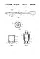
- FIG. 1is a side elevational view of a Foley catheter constructed having incorporated therein a valve retainer means in accordance with one embodiment of the present invention
- FIG. 2is a cross-sectional view taken along line 2--2 of FIG. 1;
- FIG. 3is a side elevational view of a retainer member constructed according to the teachings of the present invention.
- FIG. 4is a bottom view of the retainer member of FIG. 3;
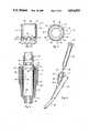
- FIG. 5is an enlarged cross-sectional view through the center of a medical device mounted in the end of a tubular member having the subject retainer means mounted thereon;
- FIG. 6is a cross-sectional view taken through the center of another embodiment of the subject retainer
- FIG. 7is a cross-sectional view through the center of a tubular member and a retainer member of the type shown in FIG. 6;
- FIG. 8is a side elevational view of a catheter device having valve means mounted in the end portion of a tubular member and held in place by retainer means constructed according to the present invention.
- number 1 in FIG. 1refers to one embodiment of a medical device shown as a urinal or Foley catheter adapted to insertion through the urethral canal and into the bladder of a patient for draining urine from the patient.
- the catheter 1includes a main catheter tube or shaft 2 having a cuff or balloon 3 surrounding a distal end portion of tube 2 and a radially outwardly tapered connector portion 4 at the proximal end for connection to a drainage tube and urine collection container or bag (not shown).
- catheter 1has longitudinally extending main and auxiliary or inflation lumens indicated at 5 and 6, repsectively.
- Tube 2has a plurality of openings 7 at the distal end which connect with main lumen 5.
- An opening 8which extends into the sidewall of the tube connects the distal end of the inflation lumen with the interior of balloon 3.
- the proximal end of the inflation lumenis connected with an inflation tube 9 having an inflation valve retainer 10 securing an inflation valve 11 within the proximal end of the inflation tube.
- the retainer 10as best seen in FIGS. 3-5, has a tubular wall portion 12 that extends between spaced opposite ends one of which is partially closed by annular flange 14, and the opposite end 16 has a plurality of spaced endwardly extending bendable tabs 18 integrally attached thereto.
- Each of the tabs 18has spaced and opposed side walls 20 and 22 which are shown at an angle relative to the axis of the tubular body such that the tabs 18 become narrower from their attached ends to their free ends.
- the free ends of the tabsare also shown formed with spaced points 23 and 24 formed by the respective side edges 20 and 22 and end edges 26 and 28 as shown.
- Each of the tabs 18also has a groove 30 formed in the outer surface thereof making the tabs 18 relatively easy to bend relative to the body portion 12.
- FIG. 4is a bottom plan view of the retainer 10 shown in FIG. 3 showing the construction with six spaced tabs 18. Also shown in FIG. 4 is the opening 32 formed by the flange 14. The opening may have different shapes including the shape shown in FIGS. 3 and 4 defined by a beveled portion 34 and a cylindrical portion 36 to receive and accommodate the member that extends therethrough. The spacing and tapering of the tabs 18 enables the tabs to be bent to positions adjacent to the inner surface 38 of the retainer without overlapping.
- FIG. 5shows a valve member 11 mounted on tube 9 which is formed of relatively soft and resilient plastic material such as rubber, latex, silicone, polyurethane or other soft polymer.
- the tube 9has a tubular proximal end portion 40 shaped to receive the valve 11 which is inserted therein into the position shown.
- the device 11has an annular outwardly extending flange portion 44 which bears against the end surface 46 of the tubular end portion 40 and in the embodiment shown, the end portion 40 also is connected to a smaller diameter tubular portion 48 of the tube 9 which is connected at the opposite end to the distal end of inflation lumen 6.
- the valve 11has a main cylindrical valve portion 50 which is positioned so as to extend into the tubular member 40, and a smaller diameter endwardly extending or operator portion 52 which extends outwardly from the proximal end of end portion 40 as shown.
- the subject retainer device 10can be installed as will be explained. First, it is necessary to the installation to deflect or bend all of the tabs 18 inwardly in order to start moving the retainer 10 onto the tubular end portion 40. With the tabs bent inwardly it is then possible to relatively easily slide the retainer member 10 into its fully seated position as shown. In this position the tabs 18 bear against the outer surface of the end portion 40 deflecting a portion of it inwardly and forming a bulge 54 against the tip portions 23 and 24 and the associated end surfaces 26 and 28.
- This bulgingprovides a positive gripping action between the tabs 18 and the end portion 40 making it virtually impossible to remove the retainer member 10 from the inflation tube 9 without destroying or damaging the end portion 40 in the process. It is significant to note that the grooves 30 formed on the outer surfaces of the tabs 18 stretch to the condition shown in FIG. 5 and in so doing narrow the distal end portion of the retainer 10. However, since the tabs are bent inwardly and backwardly, it is relatively easy to start the retainer 10 on the tubular end portion 40 and to complete the sliding thereof onto the outer surface of the portion 40.
- FIG. 6there is shown a modified embodiment 60 of the retainer member which is similar to the retainer 10 except for the fact that grooves 62 in the tabs 64 are formed on the inner rather than the outer surfaces of the tabs. This means that when the tabs are folded inwardly adjacent to the inner surface 66 of the retainer 60 that the folding will produce cavities along the fold lines of the tabs on the inner surfaces thereof.
- FIG. 7wherein the retainer 60 is shown mounted on the end of a tubular member 68 which may be a flexible tube to hold a valve assembly 70 in place therein.
- the operation of the retainer device 60is the same as the retainer device 10 with the difference noted above.
- the tabs 18can have optional sidewardly extending projections such as the projections 84 shown in dotted outline in FIG. 6.
- the projections 84are located on the sides of the tabs that engage the end portion of the tubes 9 or 68 on which they are installed to provide even greater gripping action.
- FIG. 8shows the proximal end portion of a typical device 90, such as a medical tube or catheter, on which the subject retainers 10 or 60 are installed.
- the deviceis a catheter, such as an endotracheal catheter having a main tube 92 which, in use, will extend into the throat.
- the catheter 90also has the tubular connection provided by the tube portion 48 which has an enlarged or bulbous end portion similar to the portion 40 described above into which the valve assembly 11 is positioned.
- the valve assembly 11has a tubular inlet passageway 94 which cooperates with an outlet tube or tip 96 on a syringe or like device 98.
- the syringehas a slidable piston 100, which is withdrawn to fill the syringe with a fluid such as air or a liquid such as a saline solution or other medication.
- the syringe tip 96is positioned to sealably engage the mating tubular valve inlet tube 94.
- the piston 100is moved so as to expel the fluid contained in the syringe through the valve 11 for entry into the catheter tube.
- the syringecan be used to charge air thereto for inflation. The valve will then act to maintain such balloon in inflated condition.
- the present retainer meanshas many different applications other than those described and is especially useful for installing members in the ends of relatively soft flexible plastic or plastic-like substances. It is also important that the valve means installed in tubes in such devices be installed so as to not come apart, work loose, or be damaged. Reliability is extremely important for such devices. It is obvious however that there are many other possible uses and applications for the subject device.
Landscapes
- Health & Medical Sciences (AREA)
- Life Sciences & Earth Sciences (AREA)
- Heart & Thoracic Surgery (AREA)
- Engineering & Computer Science (AREA)
- Biophysics (AREA)
- Pulmonology (AREA)
- Child & Adolescent Psychology (AREA)
- Anesthesiology (AREA)
- Biomedical Technology (AREA)
- Hematology (AREA)
- Animal Behavior & Ethology (AREA)
- General Health & Medical Sciences (AREA)
- Public Health (AREA)
- Veterinary Medicine (AREA)
- Infusion, Injection, And Reservoir Apparatuses (AREA)
Abstract
Description
Claims (20)
Priority Applications (1)
| Application Number | Priority Date | Filing Date | Title |
|---|---|---|---|
| US07/101,801US4816020A (en) | 1987-09-28 | 1987-09-28 | Retainer device for attaching members to flexible tubes and the like to flexible tubes and the like |
Applications Claiming Priority (1)
| Application Number | Priority Date | Filing Date | Title |
|---|---|---|---|
| US07/101,801US4816020A (en) | 1987-09-28 | 1987-09-28 | Retainer device for attaching members to flexible tubes and the like to flexible tubes and the like |
Publications (1)
| Publication Number | Publication Date |
|---|---|
| US4816020Atrue US4816020A (en) | 1989-03-28 |
Family
ID=22286478
Family Applications (1)
| Application Number | Title | Priority Date | Filing Date |
|---|---|---|---|
| US07/101,801Expired - LifetimeUS4816020A (en) | 1987-09-28 | 1987-09-28 | Retainer device for attaching members to flexible tubes and the like to flexible tubes and the like |
Country Status (1)
| Country | Link |
|---|---|
| US (1) | US4816020A (en) |
Cited By (30)
| Publication number | Priority date | Publication date | Assignee | Title |
|---|---|---|---|---|
| US4963133A (en)* | 1987-12-31 | 1990-10-16 | Pharmacia Deltec, Inc. | Catheter attachment system |
| US5049128A (en)* | 1990-02-06 | 1991-09-17 | Duquette Irene A | Valved infusion port |
| US5230706A (en)* | 1992-03-12 | 1993-07-27 | Duquette Irene A | Bi-directional valve assembly used in needleless injection or infusion ports |
| US5263945A (en)* | 1991-08-27 | 1993-11-23 | Contech Packaging, Inc. | Female Luer fitting with spirally spaced interior locking protuberances |
| US5360413A (en)* | 1991-12-06 | 1994-11-01 | Filtertek, Inc. | Needleless access device |
| US5395352A (en)* | 1992-02-24 | 1995-03-07 | Scimed Lift Systems, Inc. | Y-adaptor manifold with pinch valve for an intravascular catheter |
| US5399168A (en)* | 1991-08-29 | 1995-03-21 | C. R. Bard, Inc. | Implantable plural fluid cavity port |
| US5562654A (en)* | 1994-10-28 | 1996-10-08 | University Of Kentucky Research Foundation | Time-released delivery system |
| US5584875A (en)* | 1991-12-20 | 1996-12-17 | C. R. Bard, Inc. | Method for making vascular grafts |
| US5792104A (en)* | 1996-12-10 | 1998-08-11 | Medtronic, Inc. | Dual-reservoir vascular access port |
| US5865818A (en)* | 1995-06-20 | 1999-02-02 | Gould; Vincent G. | Dual function syringe and blunt assembly |
| US6039302A (en)* | 1996-11-18 | 2000-03-21 | Nypro Inc. | Swabbable luer-activated valve |
| US20020010488A1 (en)* | 2000-06-16 | 2002-01-24 | Crawford Lynn D. | Balloon occlusion device having a proximal valve |
| US20030023135A1 (en)* | 2001-06-29 | 2003-01-30 | Ulf Ulmsten | System and method for assessing urinary function |
| US20030023134A1 (en)* | 2001-06-29 | 2003-01-30 | Tracey Michael R. | System and method for assessing urinary function |
| US20030050610A1 (en)* | 2001-08-22 | 2003-03-13 | Newton Brian L. | Medical valve with expandable member |
| US20030093061A1 (en)* | 2001-11-13 | 2003-05-15 | Ganem Charles F. | Anti-drawback medical valve |
| US6755391B2 (en) | 2000-10-23 | 2004-06-29 | Nypro Inc. | Anti-drawback medical valve |
| US20040133171A1 (en)* | 2002-10-29 | 2004-07-08 | Newton Brian L. | Positive push medical valve with internal seal |
| US20050038397A1 (en)* | 2003-07-31 | 2005-02-17 | Newton Brian L. | Anti-drawback medical valve |
| US6883778B1 (en) | 1996-11-18 | 2005-04-26 | Nypro Inc. | Apparatus for reducing fluid drawback through a medical valve |
| US20060163515A1 (en)* | 2003-06-17 | 2006-07-27 | Ruschke Ricky R | Fluid handling device and method of making same |
| US20060264841A1 (en)* | 2005-01-14 | 2006-11-23 | Cote Andrew L Sr | Valve with internal lifter |
| US20060293629A1 (en)* | 2001-11-13 | 2006-12-28 | Cote Andrew L Sr | Anti-drawback medical valve |
| US20080039802A1 (en)* | 2006-08-11 | 2008-02-14 | Nypro Inc. | Medical Valve With Expandable Member |
| US7753892B2 (en) | 2001-11-13 | 2010-07-13 | Nypro Inc. | Anti-drawback medical valve |
| US7789864B2 (en) | 1996-11-18 | 2010-09-07 | Nypro Inc. | Luer-activated valve |
| US20100249724A1 (en)* | 2009-03-30 | 2010-09-30 | Np Medical Inc. | Medical Valve with Distal Seal Actuator |
| US8568371B2 (en) | 2009-06-22 | 2013-10-29 | Np Medical Inc. | Medical valve with improved back-pressure sealing |
| US9138572B2 (en) | 2010-06-24 | 2015-09-22 | Np Medical Inc. | Medical valve with fluid volume alteration |
Citations (11)
| Publication number | Priority date | Publication date | Assignee | Title |
|---|---|---|---|---|
| US3087492A (en)* | 1960-12-29 | 1963-04-30 | May L Chester | Valved catheters |
| US3131694A (en)* | 1960-12-29 | 1964-05-05 | May L Chester | Catheters |
| US3356093A (en)* | 1965-03-25 | 1967-12-05 | Oel Inc | Valved catheter |
| US3409015A (en)* | 1965-04-01 | 1968-11-05 | Davol Inc | Balloon catheter having an integral self-sealing inflation valve |
| US3495594A (en)* | 1966-11-22 | 1970-02-17 | Davol Inc | Inflating valve for catheters |
| US4232677A (en)* | 1977-06-07 | 1980-11-11 | Saul Leibinsohn | Microbe-barrier drainage device |
| US4405308A (en)* | 1981-12-23 | 1983-09-20 | The Kendall Company | Anesthesia device with selective spray ports |
| US4430081A (en)* | 1981-01-06 | 1984-02-07 | Cook, Inc. | Hemostasis sheath |
| US4484916A (en)* | 1982-01-20 | 1984-11-27 | American Hospital Supply Corporation | Medical solution container and port construction |
| US4592092A (en)* | 1982-01-20 | 1986-05-27 | American Hospital Supply Corporation | Medical solution container and port construction therefor |
| US4673393A (en)* | 1984-12-28 | 1987-06-16 | Terumo Kabushiki Kaisha | Medical instrument |
- 1987
- 1987-09-28USUS07/101,801patent/US4816020A/ennot_activeExpired - Lifetime
Patent Citations (11)
| Publication number | Priority date | Publication date | Assignee | Title |
|---|---|---|---|---|
| US3087492A (en)* | 1960-12-29 | 1963-04-30 | May L Chester | Valved catheters |
| US3131694A (en)* | 1960-12-29 | 1964-05-05 | May L Chester | Catheters |
| US3356093A (en)* | 1965-03-25 | 1967-12-05 | Oel Inc | Valved catheter |
| US3409015A (en)* | 1965-04-01 | 1968-11-05 | Davol Inc | Balloon catheter having an integral self-sealing inflation valve |
| US3495594A (en)* | 1966-11-22 | 1970-02-17 | Davol Inc | Inflating valve for catheters |
| US4232677A (en)* | 1977-06-07 | 1980-11-11 | Saul Leibinsohn | Microbe-barrier drainage device |
| US4430081A (en)* | 1981-01-06 | 1984-02-07 | Cook, Inc. | Hemostasis sheath |
| US4405308A (en)* | 1981-12-23 | 1983-09-20 | The Kendall Company | Anesthesia device with selective spray ports |
| US4484916A (en)* | 1982-01-20 | 1984-11-27 | American Hospital Supply Corporation | Medical solution container and port construction |
| US4592092A (en)* | 1982-01-20 | 1986-05-27 | American Hospital Supply Corporation | Medical solution container and port construction therefor |
| US4673393A (en)* | 1984-12-28 | 1987-06-16 | Terumo Kabushiki Kaisha | Medical instrument |
Cited By (63)
| Publication number | Priority date | Publication date | Assignee | Title |
|---|---|---|---|---|
| US4963133A (en)* | 1987-12-31 | 1990-10-16 | Pharmacia Deltec, Inc. | Catheter attachment system |
| US5049128A (en)* | 1990-02-06 | 1991-09-17 | Duquette Irene A | Valved infusion port |
| US5263945A (en)* | 1991-08-27 | 1993-11-23 | Contech Packaging, Inc. | Female Luer fitting with spirally spaced interior locking protuberances |
| US5399168A (en)* | 1991-08-29 | 1995-03-21 | C. R. Bard, Inc. | Implantable plural fluid cavity port |
| US5360413A (en)* | 1991-12-06 | 1994-11-01 | Filtertek, Inc. | Needleless access device |
| US5584875A (en)* | 1991-12-20 | 1996-12-17 | C. R. Bard, Inc. | Method for making vascular grafts |
| US5395352A (en)* | 1992-02-24 | 1995-03-07 | Scimed Lift Systems, Inc. | Y-adaptor manifold with pinch valve for an intravascular catheter |
| US5230706A (en)* | 1992-03-12 | 1993-07-27 | Duquette Irene A | Bi-directional valve assembly used in needleless injection or infusion ports |
| US5562654A (en)* | 1994-10-28 | 1996-10-08 | University Of Kentucky Research Foundation | Time-released delivery system |
| US5865818A (en)* | 1995-06-20 | 1999-02-02 | Gould; Vincent G. | Dual function syringe and blunt assembly |
| US6039302A (en)* | 1996-11-18 | 2000-03-21 | Nypro Inc. | Swabbable luer-activated valve |
| US7789864B2 (en) | 1996-11-18 | 2010-09-07 | Nypro Inc. | Luer-activated valve |
| US7100890B2 (en) | 1996-11-18 | 2006-09-05 | Nypro Inc. | Swabbable luer-activated valve |
| US6883778B1 (en) | 1996-11-18 | 2005-04-26 | Nypro Inc. | Apparatus for reducing fluid drawback through a medical valve |
| US5792104A (en)* | 1996-12-10 | 1998-08-11 | Medtronic, Inc. | Dual-reservoir vascular access port |
| US20020010488A1 (en)* | 2000-06-16 | 2002-01-24 | Crawford Lynn D. | Balloon occlusion device having a proximal valve |
| WO2001097743A3 (en)* | 2000-06-16 | 2002-05-23 | Abbott Lab | Balloon occlusion device having a proximal valve |
| AU2001271320B2 (en)* | 2000-06-16 | 2005-10-06 | Abbott Laboratories | Balloon occlusion device having a proximal valve |
| US6923822B2 (en) | 2000-06-16 | 2005-08-02 | Abbott Laboratories | Balloon occlusion device having a proximal valve |
| US6755391B2 (en) | 2000-10-23 | 2004-06-29 | Nypro Inc. | Anti-drawback medical valve |
| US7014169B2 (en) | 2000-10-23 | 2006-03-21 | Nypro Inc. | Anti-drawback medical valve |
| US20040206924A1 (en)* | 2000-10-23 | 2004-10-21 | Newton Brian L. | Anti-drawback medical valve |
| US6896650B2 (en)* | 2001-06-29 | 2005-05-24 | Ethicon Inc. | System and method for assessing urinary function |
| US20030028075A1 (en)* | 2001-06-29 | 2003-02-06 | Ulf Ulmsten | System and method for assessing urinary function |
| US20040133067A1 (en)* | 2001-06-29 | 2004-07-08 | Tracey Michael R. | System and method for assessing detrusor instability |
| US20030023135A1 (en)* | 2001-06-29 | 2003-01-30 | Ulf Ulmsten | System and method for assessing urinary function |
| US7255673B2 (en) | 2001-06-29 | 2007-08-14 | Ethicon, Inc. | System and method for assessing urinary function |
| US7252631B2 (en) | 2001-06-29 | 2007-08-07 | Ethicon, Inc. | System and method for assessing detrusor instability |
| US20030023134A1 (en)* | 2001-06-29 | 2003-01-30 | Tracey Michael R. | System and method for assessing urinary function |
| US20030027326A1 (en)* | 2001-06-29 | 2003-02-06 | Ulf Ulmsten | System and method for assessing urinary function |
| US6916283B2 (en) | 2001-06-29 | 2005-07-12 | Ethicon, Inc. | System and method for assessing urinary function |
| US20030028074A1 (en)* | 2001-06-29 | 2003-02-06 | Tracey Michael R. | System and method for assessing urinary function |
| US20030028159A1 (en)* | 2001-06-29 | 2003-02-06 | Tracey Michael R. | System and method for assessing urinary function |
| US6997884B2 (en) | 2001-06-29 | 2006-02-14 | Ethicon, Inc. | System and method for assessing urinary function |
| US7004899B2 (en) | 2001-06-29 | 2006-02-28 | Ethicon, Inc. | System and method for assessing urinary function |
| US20030050610A1 (en)* | 2001-08-22 | 2003-03-13 | Newton Brian L. | Medical valve with expandable member |
| US7396348B2 (en) | 2001-08-22 | 2008-07-08 | Nypro Inc. | Medical valve with expandable member |
| US20110066119A1 (en)* | 2001-11-13 | 2011-03-17 | Np Medical Inc. | Anti-Drawback Medical Valve |
| US7837658B2 (en) | 2001-11-13 | 2010-11-23 | Nypro Inc. | Anti-drawback medical valve |
| US20060293629A1 (en)* | 2001-11-13 | 2006-12-28 | Cote Andrew L Sr | Anti-drawback medical valve |
| US6869426B2 (en) | 2001-11-13 | 2005-03-22 | Nypro Inc. | Anti-drawback medical valve |
| US8876784B2 (en) | 2001-11-13 | 2014-11-04 | Np Medical Inc. | Anti-drawback medical valve |
| US20030093061A1 (en)* | 2001-11-13 | 2003-05-15 | Ganem Charles F. | Anti-drawback medical valve |
| US7753892B2 (en) | 2001-11-13 | 2010-07-13 | Nypro Inc. | Anti-drawback medical valve |
| US7357792B2 (en) | 2002-10-29 | 2008-04-15 | Nypro Inc. | Positive push medical valve with internal seal |
| US20040133171A1 (en)* | 2002-10-29 | 2004-07-08 | Newton Brian L. | Positive push medical valve with internal seal |
| US20060163515A1 (en)* | 2003-06-17 | 2006-07-27 | Ruschke Ricky R | Fluid handling device and method of making same |
| US20090184275A1 (en)* | 2003-06-17 | 2009-07-23 | Filtertek Inc. | Fluid handling device and method of making same |
| US7520489B2 (en) | 2003-06-17 | 2009-04-21 | Filtertek Inc. | Fluid handling device and method of making same |
| US8038123B2 (en) | 2003-06-17 | 2011-10-18 | Filtertek Inc. | Fluid handling device and method of making same |
| US20050038397A1 (en)* | 2003-07-31 | 2005-02-17 | Newton Brian L. | Anti-drawback medical valve |
| US7914502B2 (en) | 2003-07-31 | 2011-03-29 | Nypro Inc. | Anti-drawback medical valve |
| US9604047B2 (en) | 2003-07-31 | 2017-03-28 | Np Medical Inc. | Anti-drawback medical valve |
| US7887519B2 (en) | 2005-01-14 | 2011-02-15 | Nypro Inc. | Valve with internal lifter |
| US20060264841A1 (en)* | 2005-01-14 | 2006-11-23 | Cote Andrew L Sr | Valve with internal lifter |
| US8100869B2 (en) | 2006-08-11 | 2012-01-24 | Nypro Inc. | Medical valve with expandable member |
| US20080039802A1 (en)* | 2006-08-11 | 2008-02-14 | Nypro Inc. | Medical Valve With Expandable Member |
| US20100249724A1 (en)* | 2009-03-30 | 2010-09-30 | Np Medical Inc. | Medical Valve with Distal Seal Actuator |
| US8568371B2 (en) | 2009-06-22 | 2013-10-29 | Np Medical Inc. | Medical valve with improved back-pressure sealing |
| US9259565B2 (en) | 2009-06-22 | 2016-02-16 | Np Medical Inc. | Medical valve with improved back-pressure sealing |
| US9849274B2 (en) | 2009-06-22 | 2017-12-26 | Np Medical Inc. | Medical valve with improved back-pressure sealing |
| US10744314B2 (en) | 2009-06-22 | 2020-08-18 | Np Medical Inc. | Medical valve with improved back-pressure sealing |
| US9138572B2 (en) | 2010-06-24 | 2015-09-22 | Np Medical Inc. | Medical valve with fluid volume alteration |
Similar Documents
| Publication | Publication Date | Title |
|---|---|---|
| US4816020A (en) | Retainer device for attaching members to flexible tubes and the like to flexible tubes and the like | |
| US3805794A (en) | Antegrade-retrograde retention catheter | |
| US6264631B1 (en) | Catheter with distally distending balloon | |
| US4235232A (en) | Hub device for preventing liquid leakage | |
| EP0417189B1 (en) | Balloon dilation catheter | |
| US5836951A (en) | Balloon dilation catheter | |
| US5197952A (en) | Auto-inflating catheter cuff | |
| US5300023A (en) | Apparatus and method for independent movement of an instrument within a linear catheter | |
| CA1330187C (en) | Balloon dilation catheter | |
| US4228802A (en) | Self-inflating and self-cleaning catheter assembly | |
| US5312430A (en) | Balloon dilation catheter | |
| US3630206A (en) | Bladder catheter | |
| US7534224B2 (en) | Catheter with unitary component | |
| US3726283A (en) | Body-retained catheter | |
| AU613247B2 (en) | Prostate balloon dilator | |
| US3726282A (en) | Inflation valve for catheter retention balloon | |
| US3811450A (en) | Catheters | |
| US20100191183A1 (en) | Tip for an Insertion Device | |
| US8518020B2 (en) | Safety urinary catheter | |
| US7914497B2 (en) | Catheter | |
| US4776845A (en) | Rectal-stomal insert apparatus | |
| WO2004050165A1 (en) | Catheter having a balloon member invertedly attached thereto | |
| US10894148B2 (en) | Balloon-manipulating devices, balloon catheter assemblies, and methods thereof | |
| US4610663A (en) | Nephrostomy catheter with side connector | |
| JPS5910969Y2 (en) | Balloon catheter for endoscope |
Legal Events
| Date | Code | Title | Description |
|---|---|---|---|
| AS | Assignment | Owner name:SHERWOOD MEDICAL COMPANY, 1831 OLIVE STREET, ST. L Free format text:ASSIGNMENT OF ASSIGNORS INTEREST.;ASSIGNOR:BROWNELL, RICHARD G.;REEL/FRAME:004976/0916 Effective date:19871023 | |
| STCF | Information on status: patent grant | Free format text:PATENTED CASE | |
| FEPP | Fee payment procedure | Free format text:PAYOR NUMBER ASSIGNED (ORIGINAL EVENT CODE: ASPN); ENTITY STATUS OF PATENT OWNER: LARGE ENTITY | |
| FPAY | Fee payment | Year of fee payment:4 | |
| FPAY | Fee payment | Year of fee payment:8 | |
| AS | Assignment | Owner name:SHERWOOD SERVICES AG, SWITZERLAND Free format text:ASSIGNMENT OF ASSIGNORS INTEREST;ASSIGNOR:TYCO GROUP S.A.R.L.;REEL/FRAME:010180/0294 Effective date:19990406 Owner name:TYCO GROUP S.A.R.L., LUXEMBOURG Free format text:ASSIGNMENT OF ASSIGNORS INTEREST;ASSIGNOR:SHERWOOD MEDICAL COMPANY;REEL/FRAME:010255/0446 Effective date:19990406 | |
| FEPP | Fee payment procedure | Free format text:PAYOR NUMBER ASSIGNED (ORIGINAL EVENT CODE: ASPN); ENTITY STATUS OF PATENT OWNER: LARGE ENTITY Free format text:PAYER NUMBER DE-ASSIGNED (ORIGINAL EVENT CODE: RMPN); ENTITY STATUS OF PATENT OWNER: LARGE ENTITY | |
| FPAY | Fee payment | Year of fee payment:12 |