US4815669A - Shredder - Google Patents
ShredderDownload PDFInfo
- Publication number
- US4815669A US4815669AUS07/093,236US9323687AUS4815669AUS 4815669 AUS4815669 AUS 4815669AUS 9323687 AUS9323687 AUS 9323687AUS 4815669 AUS4815669 AUS 4815669A
- Authority
- US
- United States
- Prior art keywords
- documents
- transport
- shredder
- feed roller
- detection means
- Prior art date
- Legal status (The legal status is an assumption and is not a legal conclusion. Google has not performed a legal analysis and makes no representation as to the accuracy of the status listed.)
- Expired - Lifetime
Links
- 238000001514detection methodMethods0.000claimsabstractdescription34
- 238000000926separation methodMethods0.000claimsdescription5
- 230000002159abnormal effectEffects0.000description3
- 238000012986modificationMethods0.000description3
- 230000004048modificationEffects0.000description3
- 238000005452bendingMethods0.000description1
- 239000003990capacitorSubstances0.000description1
- 230000003247decreasing effectEffects0.000description1
- 230000006866deteriorationEffects0.000description1
- 238000010586diagramMethods0.000description1
- 230000000694effectsEffects0.000description1
- 230000008030eliminationEffects0.000description1
- 238000003379elimination reactionMethods0.000description1
- 238000003780insertionMethods0.000description1
- 230000037431insertionEffects0.000description1
- 230000010355oscillationEffects0.000description1
- 229920003051synthetic elastomerPolymers0.000description1
- 239000005061synthetic rubberSubstances0.000description1
Images

Classifications
- B—PERFORMING OPERATIONS; TRANSPORTING
- B02—CRUSHING, PULVERISING, OR DISINTEGRATING; PREPARATORY TREATMENT OF GRAIN FOR MILLING
- B02C—CRUSHING, PULVERISING, OR DISINTEGRATING IN GENERAL; MILLING GRAIN
- B02C18/00—Disintegrating by knives or other cutting or tearing members which chop material into fragments
- B02C18/06—Disintegrating by knives or other cutting or tearing members which chop material into fragments with rotating knives
- B02C18/16—Details
- B02C18/22—Feed or discharge means
- B02C18/2225—Feed means
- B02C18/2283—Feed means using rollers
- B—PERFORMING OPERATIONS; TRANSPORTING
- B02—CRUSHING, PULVERISING, OR DISINTEGRATING; PREPARATORY TREATMENT OF GRAIN FOR MILLING
- B02C—CRUSHING, PULVERISING, OR DISINTEGRATING IN GENERAL; MILLING GRAIN
- B02C18/00—Disintegrating by knives or other cutting or tearing members which chop material into fragments
- B02C18/0007—Disintegrating by knives or other cutting or tearing members which chop material into fragments specially adapted for disintegrating documents
- B02C2018/0023—Switching devices
Definitions
- the present inventionrelates to a shredder having a document feeding function, in which a number of documents stacked on a document feeding tray are delivered, at least, one sheet by one sheet to a pair of shredding blades so as to be shredded by the shredding blades.
- shreddersincluding a feed roller for feeding documents stacked on a document feeding tray and means for preventing many of the documents from being transported at a time
- the documentsare fed, at least, one sheet by one sheet through separation of the documents by the feed roller and are delivered from a transport path to a pair of shredding blades so as to be shredded by the shredding blades.
- documents to be shredded under conditions exceeding strength and a maximum rotational load of the shredding bladesare prevented from being transported to the shredding blades by decreasing curvature and size of the transport path. Namely, generally, as thickness of documents increases, stiffness of the documents increases. Hence, the thick documents cannot follow the small curvature and thus, stop in the course of the transport path.
- an essential object of the present inventionis to provide a shredder in which a feed roller, etc. are protected by preventing feed and transport of documents incapable of being shredded by the shredder and by controlling stoppage of the drive for the feed roller, etc., with substantial elimination of the disadvantages inherent in conventional shredders of this kind.
- a shredder embodying the present inventioncomprises: a storage means for placing thereon a number of documents to be shredded; a separate transport means for transporting the documents, at least, one sheet by one sheet through separation of the documents; a transport preventing means for preventing transport of an unsuitable document incapable of being shredded by said shredder; a transport path for transporting the documents to shredding blades; a detection means for detecting the documents, which is provided in said transport path; and a control circuit which stops said separate transport means when a signal indicative of absence of the documents has been output at a predetermined time by said detection means.
- the control circuitmakes, through determination of presence and absence of the documents on the tray, a decision as to whether or not the document detection switch is in the ON state upon lapse of a predetermined time period after start of feed of the documents. At this time, if the document detection switch is not in the ON state, drive of the first feed roller is stopped. Thus, wear of the first feed roller due to its drive is prevented and damage of the first feed roller under abnormal operating conditions is prevented.
- FIG. 1is a schematic view of a shredder according to one preferred embodiment of the present invention
- FIG. 2is a time chart indicative of control of the shredder of FIG. 1;
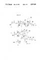
- FIG. 4is an electrical circuit diagram of a control circuit employed in the shredder of FIG. 1.
- the shredderincludes a storage device 2 for placing thereon a number of documents 1 to be shredded, a separate transport device 3 for transporting the documents 1 at least one sheet by one sheet, a transport preventing device 4 for preventing transport of the documents 1 incapable of being shredded by the shredder, a transport path 6 for transporting the documents 1 to a pair of shredding blades 5, a document sensor 7 provided in the transport path 6 and a control circuit 8 which stops the separate transport device 3 when a typical indicative of absence of the document 1 has been outputted at a predetermined time by the document sensor 7.
- the storage device 2is constituted by a tray 11 for placing the documents 1 thereon and a spring 13 for urging a rear end of the tray 11 upwardly so as to bring an uppermost one of the documents 1 on the tray 11 into contact with a first feed roller 12.
- the tray 11is pivotally mounted, at its front end, on a shredder housing 9 through a transverse shaft 10.
- a detection switch S1 for detecting presence and absence of the documents 1 placed on the tray 11is retractably provided at a central portion of the tray 11.
- the separate transport device 3is constituted by the first feed roller 12, a second feed roller 15, a belt 16 for driving the first and second feed roller 12 and 15 synchronously and a friction plate 17 for preventing a plurality of the documents 1 from being simultaneously transported.
- the first feed roller 12is rotatably supported by the shredder housing 9 so as to be disposed above the tray 11, while the friction plate 17 is made of synthetic rubber and is bonded to an upper face of a support stand 9A of the shredder housing 9 so as to be disposed below the second feed roller 15.
- the transport preventing device 4is constituted by a bent portion 18a of an upper end of an upper guide plate 18 of the transport path 6 disposed obliquely downwardly from the friction plate 17 and the friction plate 17.
- the upper end of the upper guide plate 18 of the transport path 6is bent horizontally forwardly and the friction plate 17 is disposed horizontally.
- the transport pathis defined between the upper guide plate 18 and a lower guide plate 19 extending downwardly and rearwardly in parallel with each other.
- a pair of a the shredding blades 5are of rotary type and are rotatably supported by the shredder housing 9.
- the shredderfurther includes a storage container 21, a door 22 and a cover 23.
- the control circuit 8is described with reference to FIG. 3.
- the control circuit 8is constituted by a first operational amplifier T1, a delay circuit 27, a second operational amplifier T2 and a timer circuit 28.
- On-off signals of an operation switch S2 and the detection switch S1are applied to the non-inverting input of the first operational amplifier T1, while a voltage divided by resistors R1 and R2 is applied to the inverting input of the first operational amplifier T1.
- the delay circuit 27outputs, after a delay of a first time period t1, a signal to a drive circuit 26 for driving a document feeding clutch to the first and second feed rollers 12 and 15.
- a signal of a detection switch S3 acting as the above described document sensor 7is applied to the non-inverting input of the second operational amplifier T2, while a voltage divided by resistors R3 and R4 is applied to the inverting input of the second operational amplifier T2.
- the timer circuit 28outputs a jam signal indicative of jamming of the documents 1.
- the delay circuit 27includes a third operational amplifier T3.
- the output terminal of the first operational amplifier T1is connected to the non-inverting input of the third operational amplifier T3 through a capacitor C, a resistor R5, an inverter Q1 and a diode D1, while the junction of resistors R6 and R7 is connected to the inverting input of the third operational amplifier T3.
- the timer circuit 28is constituted by a first AND circuit A1, a second AND circuit A2, a counter circuit 30 and an OR circuit B for resetting the counter circuit 30.
- One input terminal of the first AND circuit A1is connected to the output terminal of the first operational amplifier T1, while the other input terminal of the first AND circuit A1 is connected to the output terminal of the second operational amplifier T2.
- One input terminal of the second AND circuit A2is connected, through a inverter Q2, to the output terminal of the first AND circuit A1, while the other input terminal of the second AND circuit A2 is connected to an oscillation circuit 29.
- the counter circuit 28In response to an output signal of the second AND circuit A2, the counter circuit 28 outputs, after the second time period t2, a signal (high level signal) indicative of absence of the document 1 to a third AND circuit A3 via an invertor Q3.
- One input terminal of the OR circuit Bis connected to the output terminal of the first operational amplifier T1, while the other input terminal of the OR circuit B is connected to the output terminal of the second operational amplifier T2.
- the tray 11is pivoted according to the quantity of the documents 1 by the urging force of the spring 13 such that an uppermost one of the documents 1 is brought into contact with the first feed roller 12.
- the friction plate 17prevents a plurality of the documents 1 from being transported at a time.
- the document 1 delivered to the shredding blades 5is conveyed through the transport path 6 by a shredding force of the shredding blades 5.
- the feed roller 12carries to the transport path 6 and the shredding blades 6 a plurality of the documents 1 overlapping in a beltlike manner. At this time, even if an unsuitable document incapable of being shredded is inserted into the documents 1, transport of the unsuitable document is stopped by the transport preventing device 4. However, unless the detection switch S1 provided on the upper face and the lower face of the tray 11 is turned off, drive of the feed roller 12 is continued.
- the detection switch S3When transport of the unsuitable document incapable of being shredded stops due to insertion of the unsuitable document into the documents 1, the detection switch S3 provided in the course of the straight transport portion 6A detects presence and absence of the document 1. Only in the case where the detection switch S3 has detected that no document 1 has passed through the straight transport portion 6A during the second time period t2, drive of the first feed roller 12 is stopped.
- the second time period t2is determined on the basis of a time period required for transporting the document 1 to the detection switch S3 through drive of the first feed roller 12, namely, transport speed and transport distance of the document 1.
- the detection switch S1is turned on so as to indicate that there are the documents 1 on the tray 11.
- the document feed start switch (operation switch) S2is turned on, the first feed roller 12 is driven. If the document 1 capable of being shredded is transported, the detection switch S3 is turned on after the second time period t2.
- the unsuitable documentif an unsuitable document incapable of being shredded is fed, the unsuitable document does not pass through the transport path 6 after the second time period t2. Hence, the second time period t2 is counted by the timer circuit 28. If an ON signal is not outputted from the detection switch S3 upon lapse of the second time period t2, the jam signal indicative of jamming of the documents 1 is outputted and the first feed roller 12 is stopped.
- control circuit 8 of FIG. 3can also be replaced by a microcomputer.
- the control circuitmakes, through determination of presence and absence of the document on the tray, a decision as to whether or not the detection switch is in the ON state upon lapse of a predetermined time period after start of feed of the document. If the detection switch is not in the ON state, drive of the first feed roller is stopped.
Landscapes
- Engineering & Computer Science (AREA)
- Food Science & Technology (AREA)
- Crushing And Pulverization Processes (AREA)
Abstract
Description
Claims (8)
Applications Claiming Priority (2)
| Application Number | Priority Date | Filing Date | Title |
|---|---|---|---|
| JP61211111AJPS6365961A (en) | 1986-09-08 | 1986-09-08 | Document shredder |
| JP61-211111 | 1986-09-08 |
Publications (1)
| Publication Number | Publication Date |
|---|---|
| US4815669Atrue US4815669A (en) | 1989-03-28 |
Family
ID=16600589
Family Applications (1)
| Application Number | Title | Priority Date | Filing Date |
|---|---|---|---|
| US07/093,236Expired - LifetimeUS4815669A (en) | 1986-09-08 | 1987-09-04 | Shredder |
Country Status (4)
| Country | Link |
|---|---|
| US (1) | US4815669A (en) |
| JP (1) | JPS6365961A (en) |
| DE (1) | DE3729528A1 (en) |
| GB (1) | GB2196552B (en) |
Cited By (30)
| Publication number | Priority date | Publication date | Assignee | Title |
|---|---|---|---|---|
| US4964579A (en)* | 1988-03-15 | 1990-10-23 | Geha-Werke Gmbh | Document shredder with one or more trays for stacks of paper in continuous form |
| US5167374A (en)* | 1991-02-09 | 1992-12-01 | Geha-Werke Gmbh | Paper shredder with switch-off retardation |
| US5318229A (en)* | 1992-11-18 | 1994-06-07 | Brown John D | Protective device for paper shredders |
| US5362002A (en)* | 1994-01-10 | 1994-11-08 | Tsai Shao Nong | Paper shredder with automatic paper feeding device |
| US5429313A (en)* | 1993-03-22 | 1995-07-04 | Schwelling; Hermann | Paper shredder with lower cabinet and upper hood |
| US5884855A (en)* | 1998-05-13 | 1999-03-23 | Chang; Frank | Paper feed structure for paper shredders |
| US5975445A (en)* | 1997-04-14 | 1999-11-02 | Ko; Joseph Y. | Paper shredding device |
| US20070273079A1 (en)* | 2006-05-25 | 2007-11-29 | Ktf Corporation | Automatic paper feeding mechanism and automatic paper feeding device |
| US20090014565A1 (en)* | 2007-07-13 | 2009-01-15 | Fellowes Inc. | Shredder auto feed system |
| US20090032629A1 (en)* | 2007-08-02 | 2009-02-05 | Acco Uk Limited | Shredding machine |
| US20100170967A1 (en)* | 2009-01-05 | 2010-07-08 | Fellowes, Inc. | Thickness sensor based motor controller |
| US20100170969A1 (en)* | 2009-01-05 | 2010-07-08 | Fellowes, Inc. | Thickness adjusted motor controller |
| US20100213300A1 (en)* | 2004-09-10 | 2010-08-26 | Fellowes, Inc. | Shredder throat safety system |
| US20100288861A1 (en)* | 2009-05-15 | 2010-11-18 | Fellowes, Inc. | Paper alignment sensor arrangement |
| US20100320297A1 (en)* | 2009-06-18 | 2010-12-23 | Fellowes, Inc. | Restrictive throat mechanism for paper shredders |
| US20100320299A1 (en)* | 2009-06-18 | 2010-12-23 | Fellowes, Inc. | Restrictive throat mechanism for paper shredders |
| US7871027B2 (en) | 2008-02-13 | 2011-01-18 | Techko, Inc. | Auto feed shredder apparatus and methods |
| US20110053751A1 (en)* | 2009-08-25 | 2011-03-03 | Atul Arora | Method and machine for producing packaging cushioning |
| US20110186663A1 (en)* | 2004-09-10 | 2011-08-04 | Fellowes Inc. | Shredder with thickness detector |
| US8167223B2 (en) | 2007-07-13 | 2012-05-01 | Fellowes, Inc. | Shredder and auto feed system |
| US8348818B2 (en) | 2010-05-27 | 2013-01-08 | Sealed Air Corporation (Us) | Machine for producing packaging cushioning |
| US8382019B2 (en) | 2010-05-03 | 2013-02-26 | Fellowes, Inc. | In-rush current jam proof sensor control |
| US8393562B1 (en)* | 2010-12-10 | 2013-03-12 | Gregory B. Dunstan | Plastic shredder |
| US8424787B2 (en) | 2007-10-04 | 2013-04-23 | Fellowes, Inc. | Shredder thickness with anti-jitter feature |
| US8511593B2 (en) | 2010-05-28 | 2013-08-20 | Fellowes, Inc. | Differential jam proof sensor for a shredder |
| CN103433115A (en)* | 2013-09-05 | 2013-12-11 | 徐州徐工施维英机械有限公司 | Automatic protection control system and crushing machine |
| US8672247B2 (en) | 2005-07-11 | 2014-03-18 | Fellowes, Inc. | Shredder with thickness detector |
| US20150090818A1 (en)* | 2013-09-30 | 2015-04-02 | Fellowes, Inc. | Shredder auto feed system |
| US9186678B2 (en) | 2012-10-15 | 2015-11-17 | Fellowes, Inc. | Shredder auto feed system with paper stack separation mechanism |
| US9409182B2 (en) | 2013-03-15 | 2016-08-09 | Fellowes, Inc. | Shredder with paper separation and advancement mechanism |
Families Citing this family (3)
| Publication number | Priority date | Publication date | Assignee | Title |
|---|---|---|---|---|
| DE4121330A1 (en)* | 1991-06-28 | 1993-01-14 | Schleicher & Co Int | Document shredding machine - has intake side and conveyor with openings to accept goods with limiting gap and safety device to protect against damage. |
| JP3095114B2 (en)* | 1994-08-31 | 2000-10-03 | リコーエレメックス株式会社 | Paper feeder for shredder and paper feed method using the same |
| CN104043513A (en)* | 2014-06-20 | 2014-09-17 | 常磊 | Single-drive automatic paper feeding and shredding machine |
Citations (3)
| Publication number | Priority date | Publication date | Assignee | Title |
|---|---|---|---|---|
| US3614419A (en)* | 1970-04-06 | 1971-10-19 | Xerox Corp | Multiple sheet detection system |
| US4057243A (en)* | 1972-07-11 | 1977-11-08 | Ricoh Co., Ltd. | Sheet feed termination detector |
| US4192467A (en)* | 1977-05-06 | 1980-03-11 | Takefumi Hatanaka | Document shredder |
Family Cites Families (7)
| Publication number | Priority date | Publication date | Assignee | Title |
|---|---|---|---|---|
| DE2214799C2 (en)* | 1972-03-25 | 1984-03-15 | Eba-Maschinenfabrik Adolf Ehinger Kg, 7460 Balingen | Infeed mechanism for document shredder - has paper stack support with spring loaded upward motion towards transporting roller and deflecting edge |
| DE2214800C3 (en)* | 1972-03-25 | 1981-05-14 | Eba-Maschinenfabrik Adolf Ehinger Kg, 7460 Balingen | Shredding device with a cutting or shredding mechanism |
| DE2717522A1 (en)* | 1977-04-20 | 1978-10-26 | Wigand G | Shredder for microfilm - in which fed material is brushed shredded between cutters and profiled plate and withdrawn by fan |
| JPS53137486A (en)* | 1977-05-06 | 1978-11-30 | Takeshi Hatanaka | Document shredder |
| EP0047542B1 (en)* | 1980-09-08 | 1984-11-28 | Agfa-Gevaert N.V. | Dispenser for dispensing photographic sheets from a stack |
| DE3505074C2 (en)* | 1985-02-14 | 1987-04-16 | Alois Zettler Elektrotechnische Fabrik GmbH, 8000 München | Housing for device for destroying sheet material |
| DE3520890A1 (en)* | 1985-06-11 | 1986-12-11 | Alois Zettler Elektrotechnische Fabrik GmbH, 8000 München | DEVICE FOR PULLING LEAFS FROM A PILE PACK |
- 1986
- 1986-09-08JPJP61211111Apatent/JPS6365961A/enactiveGranted
- 1987
- 1987-09-04DEDE19873729528patent/DE3729528A1/enactiveGranted
- 1987-09-04GBGB8720811Apatent/GB2196552B/ennot_activeExpired - Lifetime
- 1987-09-04USUS07/093,236patent/US4815669A/ennot_activeExpired - Lifetime
Patent Citations (3)
| Publication number | Priority date | Publication date | Assignee | Title |
|---|---|---|---|---|
| US3614419A (en)* | 1970-04-06 | 1971-10-19 | Xerox Corp | Multiple sheet detection system |
| US4057243A (en)* | 1972-07-11 | 1977-11-08 | Ricoh Co., Ltd. | Sheet feed termination detector |
| US4192467A (en)* | 1977-05-06 | 1980-03-11 | Takefumi Hatanaka | Document shredder |
Cited By (59)
| Publication number | Priority date | Publication date | Assignee | Title |
|---|---|---|---|---|
| US5020733A (en)* | 1988-03-15 | 1991-06-04 | Geha-Werke Gmbh | Document shredder with one or more trays for stacks of paper in continuous form |
| US4964579A (en)* | 1988-03-15 | 1990-10-23 | Geha-Werke Gmbh | Document shredder with one or more trays for stacks of paper in continuous form |
| US5167374A (en)* | 1991-02-09 | 1992-12-01 | Geha-Werke Gmbh | Paper shredder with switch-off retardation |
| US5318229A (en)* | 1992-11-18 | 1994-06-07 | Brown John D | Protective device for paper shredders |
| US5429313A (en)* | 1993-03-22 | 1995-07-04 | Schwelling; Hermann | Paper shredder with lower cabinet and upper hood |
| US5362002A (en)* | 1994-01-10 | 1994-11-08 | Tsai Shao Nong | Paper shredder with automatic paper feeding device |
| US5975445A (en)* | 1997-04-14 | 1999-11-02 | Ko; Joseph Y. | Paper shredding device |
| US5884855A (en)* | 1998-05-13 | 1999-03-23 | Chang; Frank | Paper feed structure for paper shredders |
| US20110186663A1 (en)* | 2004-09-10 | 2011-08-04 | Fellowes Inc. | Shredder with thickness detector |
| US8870106B2 (en) | 2004-09-10 | 2014-10-28 | Fellowes, Inc. | Shredder with thickness detector |
| US8783592B2 (en) | 2004-09-10 | 2014-07-22 | Fellowes, Inc. | Shredder with thickness detector |
| US20100213300A1 (en)* | 2004-09-10 | 2010-08-26 | Fellowes, Inc. | Shredder throat safety system |
| US8672247B2 (en) | 2005-07-11 | 2014-03-18 | Fellowes, Inc. | Shredder with thickness detector |
| US8757526B2 (en) | 2005-07-11 | 2014-06-24 | Fellowes, Inc. | Shredder with thickness detector |
| USRE44161E1 (en) | 2005-07-11 | 2013-04-23 | Fellowes, Inc. | Shredder with thickness detector |
| US20070273079A1 (en)* | 2006-05-25 | 2007-11-29 | Ktf Corporation | Automatic paper feeding mechanism and automatic paper feeding device |
| US7828235B2 (en)* | 2007-07-13 | 2010-11-09 | Fellowes, Inc. | Shredder auto feed system |
| US8123152B2 (en) | 2007-07-13 | 2012-02-28 | Fellowes, Inc. | Shredder auto feed system |
| US20090014565A1 (en)* | 2007-07-13 | 2009-01-15 | Fellowes Inc. | Shredder auto feed system |
| US20110049277A1 (en)* | 2007-07-13 | 2011-03-03 | Fellowes Inc. | Shredder auto feed system |
| US8167223B2 (en) | 2007-07-13 | 2012-05-01 | Fellowes, Inc. | Shredder and auto feed system |
| US10576476B2 (en) | 2007-08-02 | 2020-03-03 | ACCO Brands Corporation | Shredding machine |
| US20110180641A1 (en)* | 2007-08-02 | 2011-07-28 | Acco Uk Limited | Shredding machine |
| US8162244B2 (en) | 2007-08-02 | 2012-04-24 | Acco Uk Limited | Shredding machine |
| US9669410B2 (en) | 2007-08-02 | 2017-06-06 | ACCO Brands Corporation | Shredding machine |
| US20090032629A1 (en)* | 2007-08-02 | 2009-02-05 | Acco Uk Limited | Shredding machine |
| US8424787B2 (en) | 2007-10-04 | 2013-04-23 | Fellowes, Inc. | Shredder thickness with anti-jitter feature |
| US9044759B2 (en) | 2007-10-04 | 2015-06-02 | Fellowes, Inc. | Shredder thickness with anti-jitter feature |
| US9724704B2 (en) | 2007-10-04 | 2017-08-08 | Fellowes Inc. | Shredder thickness with anti-jitter feature |
| US8500049B2 (en) | 2007-10-04 | 2013-08-06 | Fellowes, Inc. | Shredder thickness with anti-jitter feature |
| US8464767B2 (en) | 2007-10-04 | 2013-06-18 | Fellowes, Inc. | Shredder thickness with anti-jitter feature |
| US20110198425A1 (en)* | 2008-02-13 | 2011-08-18 | Techko, Inc. | Auto feed shredder apparatus and methods |
| US7871027B2 (en) | 2008-02-13 | 2011-01-18 | Techko, Inc. | Auto feed shredder apparatus and methods |
| US20100170969A1 (en)* | 2009-01-05 | 2010-07-08 | Fellowes, Inc. | Thickness adjusted motor controller |
| US8430347B2 (en) | 2009-01-05 | 2013-04-30 | Fellowes, Inc. | Thickness adjusted motor controller |
| US8201761B2 (en) | 2009-01-05 | 2012-06-19 | Fellowes, Inc. | Thickness sensor based motor controller |
| US20100170967A1 (en)* | 2009-01-05 | 2010-07-08 | Fellowes, Inc. | Thickness sensor based motor controller |
| US20100288861A1 (en)* | 2009-05-15 | 2010-11-18 | Fellowes, Inc. | Paper alignment sensor arrangement |
| US8205815B2 (en) | 2009-05-15 | 2012-06-26 | Fellowes, Inc. | Paper alignment sensor arrangement |
| US20100320297A1 (en)* | 2009-06-18 | 2010-12-23 | Fellowes, Inc. | Restrictive throat mechanism for paper shredders |
| US8678305B2 (en) | 2009-06-18 | 2014-03-25 | Fellowes, Inc. | Restrictive throat mechanism for paper shredders |
| US8550387B2 (en) | 2009-06-18 | 2013-10-08 | Tai Hoon K. Matlin | Restrictive throat mechanism for paper shredders |
| US20100320299A1 (en)* | 2009-06-18 | 2010-12-23 | Fellowes, Inc. | Restrictive throat mechanism for paper shredders |
| US9427928B2 (en) | 2009-08-25 | 2016-08-30 | Sealed Air Corporation (Us) | Method and machine for producing packaging cushioning |
| US20110053751A1 (en)* | 2009-08-25 | 2011-03-03 | Atul Arora | Method and machine for producing packaging cushioning |
| US8382019B2 (en) | 2010-05-03 | 2013-02-26 | Fellowes, Inc. | In-rush current jam proof sensor control |
| US8348818B2 (en) | 2010-05-27 | 2013-01-08 | Sealed Air Corporation (Us) | Machine for producing packaging cushioning |
| US8511593B2 (en) | 2010-05-28 | 2013-08-20 | Fellowes, Inc. | Differential jam proof sensor for a shredder |
| US8393562B1 (en)* | 2010-12-10 | 2013-03-12 | Gregory B. Dunstan | Plastic shredder |
| US9186678B2 (en) | 2012-10-15 | 2015-11-17 | Fellowes, Inc. | Shredder auto feed system with paper stack separation mechanism |
| US10124344B2 (en) | 2012-10-15 | 2018-11-13 | Fellowes, Inc. | Shredder auto feed system with paper stack separation mechanism |
| US9409182B2 (en) | 2013-03-15 | 2016-08-09 | Fellowes, Inc. | Shredder with paper separation and advancement mechanism |
| US10391502B2 (en) | 2013-03-15 | 2019-08-27 | Fellowes, Inc. | Shredder with paper separation and advancement mechanism |
| US10413909B2 (en) | 2013-03-15 | 2019-09-17 | Fellowes, Inc. | Shredder with paper separation and advancement mechanism |
| US11229914B2 (en) | 2013-03-15 | 2022-01-25 | Fellowes, Inc. | Shredder with paper separation and advancement mechanism |
| CN103433115B (en)* | 2013-09-05 | 2015-09-09 | 徐州徐工施维英机械有限公司 | A kind of Protection control system and crushing mechanism automatically |
| CN103433115A (en)* | 2013-09-05 | 2013-12-11 | 徐州徐工施维英机械有限公司 | Automatic protection control system and crushing machine |
| US20150090818A1 (en)* | 2013-09-30 | 2015-04-02 | Fellowes, Inc. | Shredder auto feed system |
| US9669411B2 (en)* | 2013-09-30 | 2017-06-06 | Fellowes, Inc. | Shredder auto feed system |
Also Published As
| Publication number | Publication date |
|---|---|
| JPS6365961A (en) | 1988-03-24 |
| DE3729528C2 (en) | 1989-04-20 |
| DE3729528A1 (en) | 1988-03-17 |
| JPH0418901B2 (en) | 1992-03-30 |
| GB2196552B (en) | 1990-01-10 |
| GB8720811D0 (en) | 1987-10-14 |
| GB2196552A (en) | 1988-05-05 |
Similar Documents
| Publication | Publication Date | Title |
|---|---|---|
| US4815669A (en) | Shredder | |
| US4151410A (en) | Document processing, jam detecting apparatus and process | |
| US6000693A (en) | Article detection via pinch-roll motion | |
| US4100925A (en) | Coin jamming detecting device | |
| US20010042956A1 (en) | Double feed detection method and device | |
| US4506876A (en) | Sheet paper attracting system | |
| US6722238B2 (en) | Method and device for feeding and cutting a rolled transfer paper with improved operability | |
| JPH07299377A (en) | Sheet feeder of shredder | |
| JPS624697B2 (en) | ||
| JPH0441349A (en) | Overlap feeding detecting device | |
| JP3446181B2 (en) | Paper sheet separating and feeding device | |
| JPH11134469A (en) | Paper counting machine | |
| JPS5829074Y2 (en) | The best way to get started | |
| JP2566959B2 (en) | Security thread detection device for paper processing machine | |
| JPH08290072A (en) | Shredder | |
| JP3669132B2 (en) | Paper transport device | |
| JPH085169Y2 (en) | Document feeder | |
| JP3447431B2 (en) | Document reading device | |
| JPH04164749A (en) | Multiple feed detecting device of sheet papers | |
| JPH04153665A (en) | electrophotographic equipment | |
| JPS5978048A (en) | Document handling device | |
| JPS63295363A (en) | Paper sheet accumulating device | |
| JP2504352B2 (en) | Document feeder | |
| TW414725B (en) | Paper feeder for paper crusher | |
| JPH08169631A (en) | Bill feeding device |
Legal Events
| Date | Code | Title | Description |
|---|---|---|---|
| AS | Assignment | Owner name:SHARP KABUSHIKI KAISHA, 22-22 NAGAIKE-CHO, ABENO-K Free format text:ASSIGNMENT OF ASSIGNORS INTEREST.;ASSIGNOR:FUJII, YOSHIHALU;REEL/FRAME:004789/0223 Effective date:19871023 Owner name:SHARP KABUSHIKI KAISHA, 22-22 NAGAIKE-CHO, ABENO-K Free format text:ASSIGNMENT OF ASSIGNORS INTEREST;ASSIGNOR:FUJII, YOSHIHALU;REEL/FRAME:004789/0223 Effective date:19871023 | |
| STCF | Information on status: patent grant | Free format text:PATENTED CASE | |
| FEPP | Fee payment procedure | Free format text:PAYOR NUMBER ASSIGNED (ORIGINAL EVENT CODE: ASPN); ENTITY STATUS OF PATENT OWNER: LARGE ENTITY | |
| FPAY | Fee payment | Year of fee payment:4 | |
| FEPP | Fee payment procedure | Free format text:PAYER NUMBER DE-ASSIGNED (ORIGINAL EVENT CODE: RMPN); ENTITY STATUS OF PATENT OWNER: LARGE ENTITY Free format text:PAYOR NUMBER ASSIGNED (ORIGINAL EVENT CODE: ASPN); ENTITY STATUS OF PATENT OWNER: LARGE ENTITY | |
| FEPP | Fee payment procedure | Free format text:PAYER NUMBER DE-ASSIGNED (ORIGINAL EVENT CODE: RMPN); ENTITY STATUS OF PATENT OWNER: LARGE ENTITY Free format text:PAYOR NUMBER ASSIGNED (ORIGINAL EVENT CODE: ASPN); ENTITY STATUS OF PATENT OWNER: LARGE ENTITY | |
| FPAY | Fee payment | Year of fee payment:8 | |
| FPAY | Fee payment | Year of fee payment:12 |