US4815472A - Multipoint pressure-sensing catheter system - Google Patents
Multipoint pressure-sensing catheter systemDownload PDFInfo
- Publication number
- US4815472A US4815472AUS07/057,884US5788487AUS4815472AUS 4815472 AUS4815472 AUS 4815472AUS 5788487 AUS5788487 AUS 5788487AUS 4815472 AUS4815472 AUS 4815472A
- Authority
- US
- United States
- Prior art keywords
- pressure
- transducer
- catheter system
- diaphragm
- signal
- Prior art date
- Legal status (The legal status is an assumption and is not a legal conclusion. Google has not performed a legal analysis and makes no representation as to the accuracy of the status listed.)
- Expired - Lifetime
Links
Images


Classifications
- G—PHYSICS
- G01—MEASURING; TESTING
- G01L—MEASURING FORCE, STRESS, TORQUE, WORK, MECHANICAL POWER, MECHANICAL EFFICIENCY, OR FLUID PRESSURE
- G01L9/00—Measuring steady of quasi-steady pressure of fluid or fluent solid material by electric or magnetic pressure-sensitive elements; Transmitting or indicating the displacement of mechanical pressure-sensitive elements, used to measure the steady or quasi-steady pressure of a fluid or fluent solid material, by electric or magnetic means
- G01L9/0041—Transmitting or indicating the displacement of flexible diaphragms
- G01L9/0072—Transmitting or indicating the displacement of flexible diaphragms using variations in capacitance
- G01L9/0073—Transmitting or indicating the displacement of flexible diaphragms using variations in capacitance using a semiconductive diaphragm
- A—HUMAN NECESSITIES
- A61—MEDICAL OR VETERINARY SCIENCE; HYGIENE
- A61B—DIAGNOSIS; SURGERY; IDENTIFICATION
- A61B5/00—Measuring for diagnostic purposes; Identification of persons
- A61B5/02—Detecting, measuring or recording for evaluating the cardiovascular system, e.g. pulse, heart rate, blood pressure or blood flow
- A61B5/021—Measuring pressure in heart or blood vessels
- A61B5/0215—Measuring pressure in heart or blood vessels by means inserted into the body
- A61B5/02158—Measuring pressure in heart or blood vessels by means inserted into the body provided with two or more sensor elements
- G—PHYSICS
- G01—MEASURING; TESTING
- G01L—MEASURING FORCE, STRESS, TORQUE, WORK, MECHANICAL POWER, MECHANICAL EFFICIENCY, OR FLUID PRESSURE
- G01L9/00—Measuring steady of quasi-steady pressure of fluid or fluent solid material by electric or magnetic pressure-sensitive elements; Transmitting or indicating the displacement of mechanical pressure-sensitive elements, used to measure the steady or quasi-steady pressure of a fluid or fluent solid material, by electric or magnetic means
- G01L9/0041—Transmitting or indicating the displacement of flexible diaphragms
- G01L9/0042—Constructional details associated with semiconductive diaphragm sensors, e.g. etching, or constructional details of non-semiconductive diaphragms
Definitions
- This inventionrelates in general to solid-state pressure sensors and methods of making them, and in particular to silicon pressure sensors having a diaphragm and supporting rim structure made from monocrystalline silicon wafers processed using etch-stop techniques.
- Typical applicationsinclude industrial process monitoring, such as the monitoring of gas flow under partial vacuums in semiconductor processing facilities to the precise control of air/fuel ratios in automobiles.
- Typical medical applicationsinclude measurement of blood pressure in surgery and in intensive care, air pressure in respiratory diseases, intrauterine pressure in obstetrics, abdominal and urinary pressure for diagnosis of disorders, and the like. In some such applications, it is desirable to measure pressure with an extremely small sensor so as not to disturb the system being monitored. For example, cardiovascular catheterization has become a major and common diagnostic tool in dealing with the cardiovascular system.
- catheter-tip pressure sensorIn angioplasty (balloon pumping) to treat occlusions in the coronary artery of the heart, there is presently no satisfactory means of judging the results on-line, that is, as treatment is being administered.
- Existing catheter-tip pressure sensorare single-point, not highly reliable, very expensive, and too large for use within the coronary artery. Also, they typically offer only low-level output signals which are very susceptible to noise and artifact.
- This back etchingis done normally with preferential etchants which give a bevel having a wall angle of about 52 degrees. Due to the thickness of the silicon wafer, much lateral area around the diaphragm of the transducer is required, thus making it difficult to produce a small device. This use of lateral space is not productive, in that it is not a functional part of the sensor.
- Other objects of the present inventioninclude eliminating the large rim areas associated with existing pressure sensors having a diaphragm and rim structure made from bulk silicon, and eliminating the need to provide a field shield plate during the electrostatic bonding process.
- Other objects of the present inventioninclude providing a pressure sensor that is capable of multipoint operation, is addressable, and is compatible for use on a multisite catheter having only two leads, namely the electrical power supply leads.
- One more objectis to provide such a sensor which allows on-chip temperature measurement for purposes of compensation.
- Yet another objectis to provide such a catheter system suitable for medical uses such as cardiovascular catheterization.
- Additional objects of the inventioninclude providing a transducer fabrication process that is fully batch in nature and does not require individual handling of small parts.
- the present inventionprovides an ultraminiature capacitive pressure sensor having a silicon diaphragm and rim structure made with a simple double-diffusion process.
- This novel diaphragm and rim structureis part of a silicon transducer chip which s electrostatically bonded to a glass support plate prior to removal of all of the wafer except for the diaphragm and rim structure.
- the novel diaphragm and rim structurefeatures a very small rim area, thus allowing the transducer to be constructed in ultraminiature form.
- capacitive pressure sensor of the present inventioncan be mounted, for example, in a 0.5 millimeter OD multistate cardiac catheter suitable for measuring blood pressure gradients inside the coronary artery of the heart.
- the silicon pressure transducerpreferably includes supporting interface circuitry on a chip fastened to the same glass support as the diaphragm and rim structure.
- a method of making a pressure sensor having a diaphragm in rim structure including bulk siliconcomprising the steps: (a) providing a silicon wafer; (b) forming at least one mesa upon the silicon wafer to be used as part of the rim structure of the pressure sensor; (c) impregnating a selected portion of the silicon wafer which includes the mesa with at least a first material which alters an etching characteristic of the first selected portion; (d) impregnating a second selected portion of the silicon wafer which will become the diaphragm of the sensor with a second material which alters an etching characteristic of the second selected portion; and (e) removing by etching at least a selected third portion of the silicon wafer adjacent to the first and second portions as part of forming the diaphragm and rim structure.
- Steps (c) and (d)are preferably performed by a deep diffusion and a shallow diffusion respectively of an impurity dopant, namely
- an ultraminiature solid-state capacitive pressure transducercomprising: an integrally formed structure made from single-crystal material and having a diaphragm and a rim extending about a substantial portion of the periphery of the diaphragm, the structure having at least two dimensions orthogonal to one another of less than one millimeter.
- the transducertypically includes a glass plate that is electrostatically bonded to at least part of the rim structure, and the single-crystal material is typically a silicon.
- the first materialis typically a impurity dopant selected from a group of dopants including n-type materials and p-type materials, with the preferred p-type material being boron.
- a multipoint pressure-measuring catheter systemcomprising: a catheter; a plurality of pressure sensors spaced along the catheter; and single conduit means within the catheter for providing a path for signals to be passed between an external monitor and each of the pressure sensors.
- the pressure sensorseach include pressure transducer means for converting a sensed pressure into an internal signal, switching means for applying the internal signal to the signal conduit means, and addressing means responsive to a command signal from the external monitor for selectively interrupting switching means, whereby the external monitor may receive separately the internal signal generated by each of the pressure sensors.
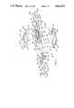
- FIG. 1is an exploded perspective view of an ultraminiature capacitive pressure sensor of the present invention which includes a silicon pressure transducer and integrated circuit chip mounted on a glass substrate;
- FIGS. 2A-2Hare a series of cross-sectional side views taken along line 2--2 of FIG. 1 showing the various processing steps associated with fabricating the silicon transducer from a silicon wafer, and bonding it to the glass support substrate;
- FIG. 3is a top cross-sectional view of the silicon pressure transducer of FIG. 1 after it is bonded to the glass substrate;
- FIG. 4is a plan view showing several completed glass silicon transducers from a matrix array of such chips which have been simultaneously bonded to a glass plate using the batch processing steps of FIG. 2, prior to dicing the plate into individual sensors;
- FIG. 5is a graph showing the capacitance change versus applied pressure characteristics of one ultraminiature pressure sensor constructed in accordance with the present invention.
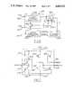
- FIG. 6is a functional block diagram of a preferred embodiment for the on-chip circuitry used in the FIG. 1 pressure sensor;
- FIG. 7is a circuit diagram of the pulse amplitude discriminator module of FIG. 6;
- FIG. 8is a circuit diagram of the two-stage counter of FIG. 6;
- FIG. 9is a detailed block diagram of the Schmitt trigger oscillator module of FIG. 6;
- FIG. 10is a signal timing diagram showing waveforms and timing relationships of various signals in the circuitry illustrated in FIGS. 6-10;
- FIG. 11is a multipoint pressure-sensing catheter system of the present invention which utilizes two of the FIG. 1 pressure sensors.
- an ultraminiature pressure sensor 30 of the present inventionis shown in an exploded perspective view for ease of understanding.
- the pressure sensor 30is comprised of three main components: a patterned glass support substrate 32 selectively metallized in certain areas, a patterned silicon transducer chip 34, and an interface circuit chip 36.
- the glass substratehas formed two therein grooves 40 and 42 at the left end 44 of the glass substrate 32, and an second pair of grooves 46 and 48 at the right end 50 of the glass substrate. Formed just beyond the inner end of the groove 40 and 42 are metallized bonding pads 60 and 62. Similarly, just beyond the inner ends of grooves 46 and 48 are metallized bonding pads 66 and 68. Typically, the grooves have trapezoidal cross-section.
- the grooves 40, 42, 46 and 48are metallized and are electrically connected respectively to pads 60, 62, 66 and 68.
- the grooves 40 and 42receive wires 70 and 72, while grooves 46 and 48 receive wires 76 and 78.
- the wires 80, 82, 86 and 88are respectively soldered or otherwise secured to grooves 40, 42, 46 and 48 prior to using the pressure sensor 30, as will later be described.
- a patterned metallized area or region 90containing a first (rear) and second (front) interconnect traces 96 and 98, which follow the periphery of and are spaced from a metallized rectangular pad 100 which serves as one-half of the active capacitor C X of the pressure transducer of sensor 30, namely the lower plate of capacitor C X .
- region 90are three metallized pads 101, 102 and 103 spaced apart from one another in a line perpendicular to the central longitudinal axis 105 of the glass support substrate 32.
- the first interconnect trace 96is connected at one end thereof to pad 106, and at the other end thereof to pad 66.
- the second trace 98is connected at one end thereof to pad 108 and at the other end thereof to pad 68.
- An enlarged view of the traces 96 and 98 and capacitor plate 100is provided in FIG. 3.
- the circuit chip 36contains a first set of beam leads 110 and 112, at the left and thereof, and a second set of beam leads 116, 117 and 118 at the right end thereof. As indicated by dashed lines 120, the circuit chip 36 is assembled to the glass support substrate 32 by flipping chip 36 over so that the beam leads 110, 112, 116, 117 and 118 respectively about against and may be bonded to bonding pads 60, 62, 106, 107 and 108 by ultrasonic bonding or thermocompression.
- the patterned transducer chip 34is preferably made from a conventional single crystal silicon wafer of the type widely used in the semiconductor industry.
- the chip 34contains a very thin centrally located diaphragm 130 which is integrally connected to and surrounded by a much thicker rectangular rim 132.
- the rim 132is preferably formed with at least two reference pressure inlet channels 133 and 134 respectively located on opposite sides of the rim, and which (until sealed off) provide access to a small space or chamber 135 under diaphragm 130.
- the silicon transducer chip 34is electrostatically bonded to the glass substrate 32 in the location indicated in phantom by-dotted lines 136.
- the circuit chip 36preferably contains all of the necessary read-out electronics, as will be further explained.
- FIGS. 1 through 4Key parts of the structure and process for making the pressure sensor 30 are the structure and process for making the transducer chip 34, and the process for joining of this chip to the glass substrate 32. This process and the resulting structure is illustrated in FIGS. 1 through 4.
- the fabrication processstarts with a 250 micron thick borosilicate glass plate 138 which may be a Corning 7740 glass plate, and which becomes the patterned glass plate 32 after processing. Since the height of the gap between the metallized capacitor plate 100 and silicon diaphragm 130 shown in FIG. 1 is typically less than 5 microns, a very smooth finish on both plates 100 and 140 are important in achieving high yield. Grooves 40, 42, 46 and 48 are first etched into the glass plate 32 with concentrated hydrofluoric (HF) acid using a gold/chromium mask.
- HFhydrofluoric
- the gold/chromium maskis preferably formed in two layers by vacuum evaporation, with the chromium layer being about 200 to 400 angstroms thick and being deposited first, and the gold layer being about 3,000 to 5,000 angstroms thick.
- This maskis patterned using conventional photolithographic techniques so that the HF acid isotropically attacks the glass only in the area where the grooves are desired.
- the two layer maskis completely removed and a second multiple-layer conductive coating is deposited everywhere on the glass, and photolithographically patterned to form the appropriate metallized areas, namely grooves 40, 42, 46 and 48, bonding pads 60, 62, 66 and 68, interconnects 96 and 98 the lower plate 100 of the active capacitor (i.e., the transducer capacitor), and the metal pads 106, 107 and 108.
- a second multiple-layer conductive coatingis deposited everywhere on the glass, and photolithographically patterned to form the appropriate metallized areas, namely grooves 40, 42, 46 and 48, bonding pads 60, 62, 66 and 68, interconnects 96 and 98 the lower plate 100 of the active capacitor (i.e., the transducer capacitor), and the metal pads 106, 107 and 108.
- the multiple-layer conductive coatingmay be made of a first layer of chromium about 300 angstroms thick for good adhesion to the glass substrate 32, and a second layer of gold about 2000 to 4000 angstroms thick for making good electrical contact with the wires, beam leads and the like connected thereto.
- a combination of three metal layersconsisting of a first layer of titanium, a second layer of platinum, and third or top layer of gold could be used as the conductive coating.
- the titanium and platinum layersshould have a combined thickness of about 200 to 300 angstroms, while the gold layer should have a thickness of 2000 to 4000 angstroms. As is shown in FIG.
- an area of overlap 139 between the rim 132 and the interconnect trace 96 in the vicinity of the metal pad 66provides the electrical connection between the rim 132 and trace 96.
- the rim 132serves as the conductive path leading to the top plate of the transducer capacitor, namely the silicon diaphragm 130.
- the wafer 140is first cleaned.
- the wafer 140is next thermally oxidized to a thickness of about 0.5 microns on all surfaces as indicated by a top layer 142 and bottom layer 144 of silicon dioxide in FIG. 2A.
- the wafer 140is then coated with a layer of photoresist, which is then patterned in accordance with a first mask so as to leave resist in two flattened U sections 146 and 148 shown in FIG. 3, with cross-sectional portions of sections 146 and 148 thereof being shown in FIG. 2A.
- the wafersare aligned in a mask aligner so that the 110-orientation flat is parallel to the long side of the diaphragm 100.
- the silicon dioxide of top layer 142is then patterned, and undesired areas thereof removed, leaving SiO 2 portions 152 and 154 located under the remaining photoresist portions 146 and 148.
- the photoresist portions 146 and 148are then removed.
- the shallow recessed sections 156, 158 and 160are removed by etching the top of the silicon wafer 140 using potassium hydroxide as an etchant and the silicon dioxide portions 152 and 154 as a mask.
- the recesses 156-160have positioned therebetween unetched mesas 162 and 164 respectively located under silicon dioxide portions 152 and 154.
- the recesses 156 and 160provide the horizontal spacing between adjacent transducers, while the recess 158 forms the gap which become space 136 in the transducer capacitor.
- the silicon dioxide portions 152 and 154are etched away with buffered HF acid.
- silion dioxideis thermally grown to a thickness of about 1.2 microns and conforms to the existing mesa structure shape. It is then photolithographically patterned in accordance with a second mask whose geometry is depicted in FIG. 3 by large and small rectangles 176 and 178 shown in dashed lines. After this patterning, as shown in FIG. 2C, the silicon dioxide portions 178, 180 and 181 remain.
- the silicon wafer 140is then impregnated in selected areas with etch-rate altering impurities by performing a deep boron diffusion, using the oxide mask portions 178, 180 and 181 to prevent the dopant gas from diffusing too far thereunder.
- This deep boron diffusion stepdefines the intended rim areas, such as rim portions 182 and 184.
- the deep boron diffusionis preferably performed at 1175 degrees C for 15 hours using a solid dopant source (e.b., boron nitride) to provide a desired rim thickness as will be further explained.
- a solid dopant sourcee.b., boron nitride
- the doped waferis then placed in a drive-in furnace at about 1100 degrees C for 40 minutes to re-oxidize the surface boron-glass layer created during the previous step to a thickness of about 0.5 microns, as indicated by layer 188 of FIG. 2D.
- a layer 190 of photoresistis deposited over the new oxide layer and patterned by removing all portions of the photoresist in the entire transducer area 192, i.e., the area within the large rectangle 176 indicated by dashed lines in FIG. 3. Thereafter, the silicon dioxide in the transducer area 192 is removed, thus leaving oxide layer portions 196 and 198 shown in FIG. 2E.
- a short or shallow boron diffusion stepis performed in the open transducer area within rectangle 176, including in the central region 200 between rim areas 182 and 184.
- the depth of this short boron diffusionis equal to the desired thickness for the silicon diaphragm 136.
- the short boron diffusion stepis performed at 1175 degrees Centrigrade for 30 minutes.
- the diaphragm area 136may be covered with a dielectric layer for protection electrical shorts and environmental contamination.
- the dielectric layer 204is preferably a compound layer comprised of a first sublayer 205 of thermally grown oxide 1000 angstroms thick and a second sublayer 206 of of CVD silicon nitride (Si 3 N 4 ) 1000 angstroms thick.
- the resulting composite layer 204is nearly neutral in stress (or in mild tension). By altering the thickness of its sublayers, such a composite layer 204 can be readily adjusted to have a temperature coefficient closely matching that of the underlining silicon diaphragm 136.
- the dielectric layer 204is initially grown and deposited over the entire wafer 140, as indicated in FIG. 2F.
- the dielectric layer 204is removed over all areas, other than the diaphragm 136. This is done as follows. A layer 207 of photoresist is applied and patterned using a fourth mask having a geometry corresponding to the inside rectangle 178 shown in FIG. 3, so that a patterned photoresist portion 208 remains and covers the diaphragm area. Then, using a plasma (dry) etch of silicon nitride, followed by a buffered HF (wet) etch to remove the oxide layer, the dielectric layer 204 is removed from all areas of wafer 140 other than the diaphragm 136, so that only dielectric layer portion 210 remains, as best seen in FIG. 2G. The same buffered HF etch also removes the back side oxide layer 144.
- a bonding stepis performed, as illustrated in FIG. 2G, wherein the silicon wafer 140 is batch bonded to the glass plate 32 using an electrostatic (anodic) bonding technique.
- the alignment of the silicon wafer 140 to the glass substrate 32is straightforward since the glass is transparent.
- the bondingis preferably formed by heating the assembly 212 of the wafer 140 and glass substrate 32 to between 400 and 450 degrees C, and then applying 400 to 600 volts DC from a suitable power source 214 across the glass plate 32 and silicon wafer 140 for two minutes. This forms a hermetic seal between the rim structure (e.g., rim portions 182 and 184) of the wafer 140 and the glass 32.
- the electrostatic bonding of a silicon wafer to glassis widely used to construct other types of silicon capacitive pressure transducers. See for example, Y. S. Lee and K. D. Wise, "A Batch-Fabricated Silicon Capacitive Pressure Transducer With Low Temperature Sensitivity", IEEE Transactions on Electron Devices, Vol. ED-29, No. 1, pp. 42-48 (Jan. 1982), which is hereby incorporated by reference. Thus, the electrostatic bonding step need not be further described here.
- the silicon wafer glass assembly shown in FIG. 2Gis immersed in an anistropic etchant for silicon (such as ethylene-diamine/pyrocatechol/water (EDP)) and all of the silicon wafer 140 is dissolved, except for the boron doped rim portions of the wafer, such as rim portions 182 and 184, and diaphragm 136 therebetween.
- an anistropic etchant for siliconsuch as ethylene-diamine/pyrocatechol/water (EDP)
- EDPethylene-diamine/pyrocatechol/water
- FIG. 4shows a portion of a glass substrate 138 having eight glass substrates 32 prior to being diced into individual substrates.
- the four substrates 32 in the centerare shown with completed glass-silicon transducers 220 of the type shown in FIG. 2H. (To avoid cluttering the Figure, the glass substrates 32' are shown without their transducers 220.)
- the fabrication process described with respect to FIGS. 1-3is fully compatible with automated batch processing techniques which will allow the transducers 220 to be prepared en masse, that is by the hundreds (or more) from a single silicon wafer.
- the glass substrates 32 shown in FIG. 4are diced along the vertical and horizontal dashed lines 222 and 224 to separate them into individual substrates 32.
- the transducer process described aboveutilizes single-sided processing of silicon wafers having normal thickness. It requires only three non-critical masking steps to produce the patterned silicon wafer diaphragm and rim structure or chip 34, and produces a very high yield. (If the optical dielectric SiO 2 -Si 3 N 4 layer is used, then a fourth mask is required.)
- the rim and diaphragm thicknessesare set by the deep and shallow boron diffusion steps with a precision of better than 0.1 microns, while lateral dimensions are controlled by lithography to a precision of better than 0.25 microns.
- the rim sizeis scalable, but is typically 12 microns thick and 80 microns wide. This is significantly smaller than those found in conventional pressure sensing structures, in which the diaphragm is formed from a back side anisotropic etch, and the width of the rim is comparable to the wafer thickness (300 microns or more). Furthermore, in the present approach, batch wafer bonding to the glass before wafer dissolution eliminates handling of individual diaphragm structures until die separation and final packaging.
- the glass 138may be sawed into individual dies (i.e., glass plates 32) before or after the bonding of the chips 36 to the metal pads 60, 62, 106, 107 and 108.
- FIG. 5shows the measured pressure characteristics of the ultraminiature sensor illustrated in FIG. 1.
- the reference cavity 135 for the sensor 130 upon which the measurements were madewas sealed and at atmospheric pressure.
- differential pressure measurement with an unsealed reference pressure inlet channel 134is also possible with the transducer 220.
- the sensor 30 upon which the measurements shown in FIG. 4 were madehad a diaphragm size of 260 microns x 600 microns x 2 microns, a capacitor plate separation of 2.2 microns, a zero-pressure capacitance of 0.33 pF, a pressure range of about 500 mmHg and a pressure sensitivity of 1440 ppm/mmHg.
- the pressure sensitivity of the transducer 220can be scaled over several orders of magnitude.
- the circuit 250includes a pulse amplitude discriminator circuit 252, a two-stage counter 254, and a Schmitt trigger oscillator circuit 256 including a Schmitt trigger oscillator 258, an enable switch 260, and a two-position selector 262.
- circuit 250Electrical power and signal communication is delivered over conductors 266 and 268 which respectively are nominally at a solid-state circuit supply voltage VDD (such as +5VDC) and ground potential GND (0.0 volts).
- VDDsolid-state circuit supply voltage
- GNDground potential GND
- the operation of circuit 250may be explained in brief as follows.
- the electrical pressure signal originating with capacitor C xis then extracted by detecting the frequency of current variations over the power lines 266 and 268. Tradeoff between pressure signal bandwidth and resolution can be attained by altering the length of the sampling time.
- Temperature compensationis accomplished by differencing the oscillation period produced using the transducer with that of an on-chip reference capacitor C R which may be a thin film capacitor internally fabricated with the other circuit components on circuit 250 in IC chip 36.
- the reference capacitor C Rtogether with the temperature coefficient of the circuit supplying power to capacitor C R , also serves as a transducer for on-chip temperature readout.
- Site and pressure/temperature transducer addressingis accomplished by signaling over the supply line 266 to circuit 252, which triggers an on-chip counter 254 and allows one particular sensor on a bussed multisensor line to be activated, while inactivated oscillator cirucits such as circuit 256 are disabled.
- multisite operationis possible.
- By depositing a thin film metal resistor having a high temperature coefficient of resistance on the diaphragm 130it is possible to measure dynamic changes in temperature as well as pressure at each sensing site to allow future thermal dilution measurements of blood flow.
- the addressable read-out circuit 250 in FIG. 5may be fabricated on a single integrated chip such as chip 36 shown in FIG. 1.
- Prototypes of the chip 36have been fabricated using standard NMOS processing, with beam leads to allow low-capacitance low-profile high-density interconnects to the transducer 220 and output leads 60, 62, 66 and 68 via the glass substrate 32.
- circuits 250can be processed using standard IC fabrication techniques and may be realized using a chip foundry; (2) the circuitry 250 is not exposed to the high voltage needed for the electrostatic bonding process; and (3) working circuit chips 36 can be selected for bonding to transducers 220, thus improving yield.
- FIG. 7shows a detailed circuit diagram of the pulse amplitude discriminator circuit 252.
- the circuit 252contains seven metal-oxide-semiconductor (MOS) insulated-gate field effect transistors (FETs) 270 through 282.
- FETs 270-274are enhancement-mode devices, while FETs 276-282 are depletion-mode devices.
- the circuit 252receives power over supply lines 266 and 268, and receives two different types of commands over supply lines 266.
- the nominal voltage VDDis +5 volts DC.
- the first command signalis a clock signal which is delivered at +8 volts DC.
- the second command signalis a reset signal which is delivered at +11 volts DC.
- the first command signalis shown in FIG. 10 on waveform 284.
- the pulses 286are the clock pulses.
- the circuit 252produces three outputs signals, namely the RESET on line 290 and the MODE and MODE* signals on lines 292 and 294.
- a waveform 296 in FIG. 10shows the timing and voltage levels of the MODE signal.
- the MODE* signalis the complement of the MODE signal. (The asterisk symbol is used to indicate the complement of whatever signal it follows.)
- the operation of circuit 252 in FIG. 7may be briefly explained as follows. When VDD line 266 temporarily goes to 8 volts, it draws node 300 to a sufficiently high level, causing gate 298 of transistor 272 to go high, which turns transistor 272 on.
- MODE*goes from a high to a low logic level, and transistor 274 turns off, which makes the MODE signal on line 292 switch from a low logic level to a high logic level.
- VDD line 266returns to 5 volts
- gate 298returns to a low logic level causing transistor 272 to turn off.
- the MODE* signalswitches from a low to high logic level, and transistor 274 turns on which causes the MODE signal on line 292 to switch from high to low.
- the VDD linegoes to 11 volts, indicating a RESET command, it draws reset line 290 from a low to high logic level.
- FIG. 8is a circuit diagram of the two-stage counter circuit 254 shown in FIG. 6.
- the circuit 254includes a first stage 310 and a second stage 312 interconnected by a single conductor 314.
- the output signal P on line 316 of first stage 310is the low-order bit output of counter 254, while the output signal CE (which stands for Chip Enable) is the output for the high-order bit of counter 254.
- the first and second stages 310 and 312each receive the MODE, MODE* and RESET signals respectively from lines 292, 294 and 290.
- the circuit 254provides as outputs the P and P* signals on lines 316 and 320 respectively from the first stage 310, and provides as outputs the CE and CE* signals on lines 318 and 270 of the second stage 312.
- waveforms 322, 324 and 326show the timing relationships for signals P, P', and CE respectively.
- the first stage 310includes inverter 330, MOSFET 332, NOR gate 334, inverter 336 and MOSFETs 338 and 339, all connected as shown.
- the second stage 312includes: inverter 340, MOSFETs 341 and 342, NOR gate 344, inverter 346 and MOSFETs 348 and 349, all connected as shown.
- the operation of stages 310 and 312will now be briefly explained, and it will be assumed that the RESET line 290 remains at a low logic level, which causes NOR gates 334 and 344 to each function as a simple inverter. As long as the MODE* signal remains high, the transistors 338 and 348 conduct.
- stage 310the NOR gate 334 and inverter 336 act as a latch to hold on the signal present on line 320 whenever transistor 338 is on and transistor 332 is off.
- stage 312the NOR gate 344 and inverter 346 act as a latch whenever transistor 348 is on (that is, conducting) and transistor 341 or 342 is off.
- line 314the P' signal
- transistor 332turns on, causing line 350 to go low irrespective of its previous state, which causes line 316 to go high and line 320 to go low.
- the MODE signal on line 292the MODE* signal on line 294 is low and transistors 338 and 339 are off.
- stage 312contains an additional transistor 341 which only allows the output signal CE* on line 270 to change state when the MODE signal on line 292 and the signal on line 314 from stage 310 are both high.
- the operation of stage 312is the same as stage 310. Note that when the RESET signal on line 290 goes high, the outputs of NOR gates 334 and 344 are forced low irrespective of the state of input lines 350 and 356, thus causing both the P signal on line 316 and the CE signal on line 318 to go low. Transistors 338 and 348 if on will latch in this RESET output state.
- FIG. 9shows a detailed block diagram of the trigger oscillator circuit 256 shown in FIG. 6.
- the circuit 256includes a MOSFET 360, which acts as the enable swithh 260.
- the switch 260is turned on whenever the gate input line 270, containing the enable signal CE* from the second stage 312 of the counter 254 is high.
- the input to transistor 360would be the output signal CE on line 318 from the second stage 312 of counter 254. Since the enable switch 260 must be on in order for the oscillator circuit 256 to operate, it will be appreciated that the input signal to transistor 360 is effectively an address signal which must be high in order for the oscillator circuit 256 to be addressed.
- the Schmitt trigger oscillator 258consists of three components, namely an inverting Schmitt trigger 362, inverter 364 and a source 366 of approximately constant current which is provided at a predetermined level from supply line 266 to output line 368.
- the current source 366is set to produce the desired rate of charging of the transducer capacitor C X and the reference capacitor C R shown in FIG. 9.
- the switching circuit 262includes four enhancement-mode MOSFETs 370-376. The operation of circuit 256 will now be briefly explained. When circuit is enabled by a high signal on the input of transistor 360, and the output of inverter 364 on line 378 is low, transistors 372 and 376 will be off, thus permitting capacitors C X and C R to charge.
- Waveform 382 in FIG. 10illustrates the operation of the FIG. 9 circuit by showing the output voltage VOUT on line 368.
- the time period T X between t1 and t2represents the interval during which the transducer capacitor C X is being repetitively charged and discharged by circuit 256.
- the time period T R between times t0 and t1represents the interval of time during which the circuit 256 is charging and discharging the reference capacitor C R .
- the circuit 256 shown in FIG. 9is disabled, thus allowing the voltage VOUT on line 368 to approach the value of voltage VDD on line 266 as shown by waveform portion 384 of waveform 382 in FIG. 10.
- any change in the rate of charging of reference capacitor C Rcan be correlated with reasonable accuracy to changes in temperature of the integrated circuit chip 336 in which capacitor C R is located.
- C Rprovides a convenient and accurate method for determining the temperature of the pressure transducer of sensor 30, so that the pressure readings obtained from the charging time of transducer capacitor C X can be accurately compensated for temperature by an external monitoring system which examines the charging rates of capacitors C X and C R . These charging rates are monitored by monitoring the frequency of the current signal drawn by circuit 252 over power supply lines 266 and 268.
- the amount of pressure applied to the diaphragm 130 of pressure transducer 220directly influences the capacitance value of capacitor C X .
- the capacitance valueincreases. Since changes in the capacitance value of capacitor C X results in proportional changes in the charging time of capacitor C X , the pressure being applied to the diaphragm 130 can be readily determined by monitoring the frequency of the current signal on power lines 256 and 268 when capacitor C X is allowed to charge by transistor 370 being on, and transistor 372 being off, as has been discussed with respect to FIG. 9.
- the pressure transducer 220 of sensor 30can be operated in several ways.
- the pressure transducer 220can be sealed at ambient pressure, or under vacuum conditions. If sealed at ambient pressure, epoxy or other suitable sealing materials can be deposited at the openings of both reference channels 133 and 134 (see FIGS. 1 and 3).
- One disadvantage of sealing gas in the cavity or chamber 135 of the pressure transducer 220is that it results in a pressure transducer which has a high temperature coefficient on account of the pressure of the trapped gas naturally changing within sealed chamber 135 as the gas temperature changes.
- the transducers 200are to be sealed under vacuum conditions, this may be done en masse simultaneously while they are still on the glass plate 138 before the glass plate sections 32 are diced into individual glass plates, by depositing a dielectric material with sealing properties directionally through a shadow mask at the mouth or opening of each of the reference channels 134 and 135.
- This taskcan be carried out in a sputtering chamber using silicon dioxide (or the like) as the sealing material using a shadow mask which only has openings above the reference channels.
- the systemincludes a very small catheter 402 such as 0.5 mm outer diameter (OD) tubing made from polyethylene or other suitable material, which has a length sufficient for the medical (or other) purpose to which the catheter will be placed.
- the system shownhas two pressure sensors 30a and 30n, which are preferably constructed like sensor 30 shown in FIG. 1, spaced apart by a predetermined distance 404 such as 5 cm.
- the catheter 402has three distinct sections: a catheter tip section 406, preferably round and gently pointed as shown to facilitate insertion into and passage along the interior of smaller blood vessels; an intermediate section 40 between the two pressure sensors 30a and 30b; and an extension section 410 to provide a conduit through which the wire leads 266 and 268 from electronic pressure sensor monitoring equipment may pass to reach the first and closest sensor 30a.
- the catheter systemuses only the two wire leads 266 and 268 which are electrically connected in parallel to the two sensors 30a and 30n, while physically being arranged in series.
- the pressure sensors 30a and 30nwhich each include a glass plate 32 with the transducer chip 34 and read-out electronics chip 36 mounted thereon, is partially encapsulated with a biomedically compatible material 414 (i.e., one that is non-toxic and will now be adversely affected by the bodily fluids to which it be exposed) such as polyimide, silicone rubber, or the like, to seal off the hollow cylindrical interior of the catheter sections from bodily fluids.
- a biomedically compatible material 414i.e., one that is non-toxic and will now be adversely affected by the bodily fluids to which it be exposed
- a biomedically compatible material 414such as polyimide, silicone rubber, or the like
- the diaphragm 130may have encapsulating material upon it, provided that the thickness of the layer of material upon the diaphragm is controlled so as to be at least about an order of magnitude more flexible than the silicon diaphragm 310.
- the integrated circuit chip 36is preferably within the dry interior of the catheter section 408 (or section 410) where it will not be contacted by bodily fluids.
- the required catheter leads 266 and 268are attached via soldering or the like into the etched grooves 40, 42, 46 and 48 as has been explained in FIG. 1. Finally, the ends of the glass plates 32 are inserted in the catheter 402, leaving only the silicon diaphragms 130 exposed for measurement.
- the pressure transducers of the present inventionmay be made much larger or smaller than the embodiments described herein by appropriate scaling of various dimensions.
- the pressure transducer of the present inventionmay be used to sense fluid flow and other conditions by providing appropriate means for causing deflection of the diaphragm are provided. Accordingly, it is to be understood that the protection sought and to be afforded hereby would be deemed to extend to the subject matter claimed and all equivalents thereof fairly within the scope of the invention.
Landscapes
- Health & Medical Sciences (AREA)
- Life Sciences & Earth Sciences (AREA)
- Physics & Mathematics (AREA)
- General Physics & Mathematics (AREA)
- Cardiology (AREA)
- Biomedical Technology (AREA)
- Surgery (AREA)
- Biophysics (AREA)
- Pathology (AREA)
- Engineering & Computer Science (AREA)
- Vascular Medicine (AREA)
- Heart & Thoracic Surgery (AREA)
- Medical Informatics (AREA)
- Molecular Biology (AREA)
- Physiology (AREA)
- Animal Behavior & Ethology (AREA)
- General Health & Medical Sciences (AREA)
- Public Health (AREA)
- Veterinary Medicine (AREA)
- Chemical & Material Sciences (AREA)
- Analytical Chemistry (AREA)
- Measuring Fluid Pressure (AREA)
Abstract
Description
TABLE 1 ______________________________________ Catheter Size 0.5 mmOD Diaphragm Size 290 × 500 × 2 microns Transducer Die Size 0.45 × 1 mm Circuit Die Size (Prototype) 0.45 × 1.1 mm Zero-Pressure Capacitance 470 fF Pressure Accuracy 1mmHg Pressure Range 500 mmHg Signal Bandwidth 50 Hz Temperature Compensation Frequency Differencing Using an On-Chip Reference CapacitorPower Supply Single 5 V Signaling Levels 8 Volts - Addressing, 11 Volts - Reset Power Dissipation less than 10 mW Output Signal Small-Signal Supply Current Variation (600 A p-p Over 850 microamps dc Baseline) Number ofSensing Sites 2 Number of Transducers/Site 2 (Pressure/On-Chip Temperature) Number ofExternal Leads 2 ______________________________________
Claims (22)
Priority Applications (5)
| Application Number | Priority Date | Filing Date | Title |
|---|---|---|---|
| US07/057,884US4815472A (en) | 1987-06-01 | 1987-06-01 | Multipoint pressure-sensing catheter system |
| US07/190,310US4881410A (en) | 1987-06-01 | 1988-05-04 | Ultraminiature pressure sensor and method of making same |
| US07/431,627US5013396A (en) | 1987-06-01 | 1989-11-03 | Method of making an ultraminiature pressure sensor |
| US07/631,655US5113868A (en) | 1987-06-01 | 1990-12-21 | Ultraminiature pressure sensor with addressable read-out circuit |
| US07/885,316US5207103A (en) | 1987-06-01 | 1992-05-18 | Ultraminiature single-crystal sensor with movable member |
Applications Claiming Priority (1)
| Application Number | Priority Date | Filing Date | Title |
|---|---|---|---|
| US07/057,884US4815472A (en) | 1987-06-01 | 1987-06-01 | Multipoint pressure-sensing catheter system |
Related Child Applications (1)
| Application Number | Title | Priority Date | Filing Date |
|---|---|---|---|
| US07/190,310DivisionUS4881410A (en) | 1987-06-01 | 1988-05-04 | Ultraminiature pressure sensor and method of making same |
Publications (1)
| Publication Number | Publication Date |
|---|---|
| US4815472Atrue US4815472A (en) | 1989-03-28 |
Family
ID=22013333
Family Applications (1)
| Application Number | Title | Priority Date | Filing Date |
|---|---|---|---|
| US07/057,884Expired - LifetimeUS4815472A (en) | 1987-06-01 | 1987-06-01 | Multipoint pressure-sensing catheter system |
Country Status (1)
| Country | Link |
|---|---|
| US (1) | US4815472A (en) |
Cited By (129)
| Publication number | Priority date | Publication date | Assignee | Title |
|---|---|---|---|---|
| US4881410A (en)* | 1987-06-01 | 1989-11-21 | The Regents Of The University Of Michigan | Ultraminiature pressure sensor and method of making same |
| US4908509A (en)* | 1988-10-27 | 1990-03-13 | Massachusetts Institute Of Technology | Traction and reaction force microsensor |
| US5013396A (en)* | 1987-06-01 | 1991-05-07 | The Regents Of The University Of Michigan | Method of making an ultraminiature pressure sensor |
| US5024240A (en)* | 1989-01-03 | 1991-06-18 | Mcconnel Fred M S | Manofluorography system, method for forming a manofluorogram and method for preparing a swallowing profile |
| US5035246A (en)* | 1987-06-30 | 1991-07-30 | Heuvelmans Joannes H A | Method for carrying out hemodynamic measurements on a patient and flow-directed balloon catheter used for this |
| US5043295A (en)* | 1987-09-09 | 1991-08-27 | Ruggerio Paul A | Method of forming an IC chip with self-aligned thin film resistors |
| DE9090044U1 (en)* | 1989-03-17 | 1991-11-21 | Merit Medical Systemc, Inc., Salt Lake City, Utah | Monitoring device for balloon catheters and associated inflatable syringes |
| US5084060A (en)* | 1989-02-15 | 1992-01-28 | Freund Precision, Inc. | Apparatus for enlarging a vessel or clearing obstructive tissue from a vessel according to vessel compliance |
| US5113868A (en)* | 1987-06-01 | 1992-05-19 | The Regents Of The University Of Michigan | Ultraminiature pressure sensor with addressable read-out circuit |
| US5141148A (en)* | 1990-07-20 | 1992-08-25 | Mitsubishi Denki Kabushiki Kaisha | Method of anodic bonding a semiconductor wafer to an insulator |
| EP0522567A1 (en)* | 1991-07-12 | 1993-01-13 | Terumo Kabushiki Kaisha | Pressure converter |
| EP0509798A3 (en)* | 1991-04-16 | 1993-03-03 | Kenneth H. Ball | Transducer particularly for use in respirator apparatus |
| US5207103A (en)* | 1987-06-01 | 1993-05-04 | Wise Kensall D | Ultraminiature single-crystal sensor with movable member |
| US5343064A (en)* | 1988-03-18 | 1994-08-30 | Spangler Leland J | Fully integrated single-crystal silicon-on-insulator process, sensors and circuits |
| WO1994022518A1 (en)* | 1993-04-05 | 1994-10-13 | Harald Mang | Artificial respiration tube, process for operating artificial respiration equipment with artificial respiration tube and installation with artificial respiration equipment and tube |
| US5357807A (en)* | 1990-12-07 | 1994-10-25 | Wisconsin Alumni Research Foundation | Micromachined differential pressure transducers |
| US5383855A (en)* | 1992-08-20 | 1995-01-24 | Medex, Inc. | Electronically monitored angioplasty system |
| US5404000A (en)* | 1992-01-10 | 1995-04-04 | Microbilt Corporation | Embossed character reader for data card terminal |
| US5417235A (en)* | 1993-07-28 | 1995-05-23 | Regents Of The University Of Michigan | Integrated microvalve structures with monolithic microflow controller |
| US5488869A (en)* | 1993-02-12 | 1996-02-06 | Csem Centre Suisse D'electronique Et De Microtechnique Sa | Capacitive absolute pressure measurement sensor and method of manufacturing a plurality of such sensors |
| US5492596A (en)* | 1994-02-04 | 1996-02-20 | The Charles Stark Draper Laboratory, Inc. | Method of making a micromechanical silicon-on-glass tuning fork gyroscope |
| US5501228A (en)* | 1992-10-30 | 1996-03-26 | Scimed Life Systems, Inc. | Vibration sensing guide wire |
| US5533515A (en)* | 1994-08-11 | 1996-07-09 | Foster-Miller | Solid state sphincter myometers |
| US5535902A (en)* | 1993-02-10 | 1996-07-16 | The Charles Stark Draper Laboratory, Inc. | Gimballed vibrating wheel gyroscope |
| WO1996026674A1 (en)* | 1995-02-27 | 1996-09-06 | Medtronic, Inc. | Implantable capacitive absolute pressure and temperature monitor system |
| WO1996026670A1 (en)* | 1995-02-27 | 1996-09-06 | Medtronic, Inc. | Implantable capacitive absolute pressure and temperature sensor |
| US5581035A (en)* | 1994-08-29 | 1996-12-03 | The Charles Stark Draper Laboratory, Inc. | Micromechanical sensor with a guard band electrode |
| US5635639A (en)* | 1991-09-11 | 1997-06-03 | The Charles Stark Draper Laboratory, Inc. | Micromechanical tuning fork angular rate sensor |
| US5635739A (en)* | 1990-02-14 | 1997-06-03 | The Charles Stark Draper Laboratory, Inc. | Micromechanical angular accelerometer with auxiliary linear accelerometer |
| US5646348A (en)* | 1994-08-29 | 1997-07-08 | The Charles Stark Draper Laboratory, Inc. | Micromechanical sensor with a guard band electrode and fabrication technique therefor |
| US5650568A (en)* | 1993-02-10 | 1997-07-22 | The Charles Stark Draper Laboratory, Inc. | Gimballed vibrating wheel gyroscope having strain relief features |
| US5758652A (en)* | 1995-10-19 | 1998-06-02 | Nikolic; Serjan D. | System and method to measure the condition of a patients heart |
| US5783973A (en)* | 1997-02-24 | 1998-07-21 | The Charles Stark Draper Laboratory, Inc. | Temperature insensitive silicon oscillator and precision voltage reference formed therefrom |
| EP0714258A4 (en)* | 1993-08-19 | 1998-12-23 | Fiberoptic Sensor Tech | Dual pressure sensing catheter |
| US5871499A (en)* | 1993-06-30 | 1999-02-16 | Novatrix, Inc. | Child birth assisting system |
| US5892153A (en)* | 1996-11-21 | 1999-04-06 | The Charles Stark Draper Laboratory, Inc. | Guard bands which control out-of-plane sensitivities in tuning fork gyroscopes and other sensors |
| US5911156A (en)* | 1997-02-24 | 1999-06-08 | The Charles Stark Draper Laboratory, Inc. | Split electrode to minimize charge transients, motor amplitude mismatch errors, and sensitivity to vertical translation in tuning fork gyros and other devices |
| US5952574A (en)* | 1997-04-29 | 1999-09-14 | The Charles Stark Draper Laboratory, Inc. | Trenches to reduce charging effects and to control out-of-plane sensitivities in tuning fork gyroscopes and other sensors |
| US5964732A (en)* | 1997-02-07 | 1999-10-12 | Abbeymoor Medical, Inc. | Urethral apparatus with position indicator and methods of use thereof |
| US5971967A (en)* | 1997-08-19 | 1999-10-26 | Abbeymoor Medical, Inc. | Urethral device with anchoring system |
| US6152181A (en)* | 1992-11-16 | 2000-11-28 | The United States Of America As Represented By The Secretary Of The Air Force | Microdevices based on surface tension and wettability that function as sensors, actuators, and other devices |
| WO2001013789A1 (en)* | 1999-08-26 | 2001-03-01 | Aortech International Plc | Improvements relating to catheter positioning |
| US6264612B1 (en)* | 2000-01-14 | 2001-07-24 | Children's Hospital Medical Center | Catheter with mechano-responsive element for sensing physiological conditions |
| US20030018273A1 (en)* | 1994-09-02 | 2003-01-23 | Jomed Inc. | Guidewire with pressure and temperature sensing capabilities |
| US6553247B1 (en) | 1999-10-04 | 2003-04-22 | Polar Electro Oy | Electrode belt of heart rate monitor |
| US20030092977A1 (en)* | 2001-10-12 | 2003-05-15 | Sahatjian Ronald A. | Catheter Lesion diagnostics |
| US20030136417A1 (en)* | 2002-01-22 | 2003-07-24 | Michael Fonseca | Implantable wireless sensor |
| US20040006368A1 (en)* | 1994-07-08 | 2004-01-08 | Ev3 Inc. | Method and device for filtering body fluid |
| US20040035206A1 (en)* | 2002-03-26 | 2004-02-26 | Ward Paul A. | Microelectromechanical sensors having reduced signal bias errors and methods of manufacturing the same |
| WO2004052182A2 (en) | 2002-12-11 | 2004-06-24 | Proteus Biomedical, Inc. | Monitoring and treating hemodynamic parameters |
| US20040152229A1 (en)* | 2002-10-18 | 2004-08-05 | Khalil Najafi | Manufacturing methods and vacuum or hermetically packaged micromachined or MEMS devices formed thereby having substantially vertical feedthroughs |
| US20040215049A1 (en)* | 2003-01-24 | 2004-10-28 | Proteus Biomedical, Inc. | Method and system for remote hemodynamic monitoring |
| US20040254483A1 (en)* | 2003-01-24 | 2004-12-16 | Proteus Biomedical, Inc. | Methods and systems for measuring cardiac parameters |
| US20040261535A1 (en)* | 2003-06-30 | 2004-12-30 | Kurtz Anthony D. | Apparatus and method for interconnecting leads in a high temperature pressure transducer |
| US20050015014A1 (en)* | 2002-01-22 | 2005-01-20 | Michael Fonseca | Implantable wireless sensor for pressure measurement within the heart |
| US20050107866A1 (en)* | 2002-06-07 | 2005-05-19 | Brown Peter S. | Endovascular graft with pressor and attachment methods |
| US20050148884A1 (en)* | 2003-10-10 | 2005-07-07 | Parks Thomas R. | High resolution solid state pressure sensor |
| US20050187482A1 (en)* | 2003-09-16 | 2005-08-25 | O'brien David | Implantable wireless sensor |
| US20060058588A1 (en)* | 2004-09-02 | 2006-03-16 | Proteus Biomedical, Inc. | Methods and apparatus for tissue activation and monitoring |
| US20060074318A1 (en)* | 2004-09-27 | 2006-04-06 | Masood Ahmed | Combination sensor guidewire and methods of use |
| US7025778B2 (en) | 2002-06-07 | 2006-04-11 | Endovascular Technologies, Inc. | Endovascular graft with pressure, temperature, flow and voltage sensors |
| US20060174712A1 (en)* | 2005-02-10 | 2006-08-10 | Cardiomems, Inc. | Hermetic chamber with electrical feedthroughs |
| US20060200220A1 (en)* | 2002-06-07 | 2006-09-07 | Brown Peter S | Endovascular graft with sensors design and attachment methods |
| US20060200031A1 (en)* | 2005-03-03 | 2006-09-07 | Jason White | Apparatus and method for sensor deployment and fixation |
| US7147604B1 (en) | 2002-08-07 | 2006-12-12 | Cardiomems, Inc. | High Q factor sensor |
| US20060283007A1 (en)* | 2005-06-21 | 2006-12-21 | Cardiomems, Inc. | Method of manufacturing implantable wireless sensor for in vivo pressure measurement |
| US20060287602A1 (en)* | 2005-06-21 | 2006-12-21 | Cardiomems, Inc. | Implantable wireless sensor for in vivo pressure measurement |
| US7162926B1 (en) | 2005-08-04 | 2007-01-16 | Kavlico Corporation | Lead embedded pressure sensor |
| US7200439B2 (en) | 2003-01-24 | 2007-04-03 | Proteus Biomedical, Inc. | Method and apparatus for enhancing cardiac pacing |
| US20070096715A1 (en)* | 2004-11-01 | 2007-05-03 | Cardiomems, Inc. | Communicating with an Implanted Wireless Sensor |
| US20070123767A1 (en)* | 2002-05-31 | 2007-05-31 | Valentino Montegrande | Intraocular pressure sensor and method of use |
| US20070247138A1 (en)* | 2004-11-01 | 2007-10-25 | Miller Donald J | Communicating with an implanted wireless sensor |
| US20070261497A1 (en)* | 2005-02-10 | 2007-11-15 | Cardiomems, Inc. | Hermatic Chamber With Electrical Feedthroughs |
| US20080072912A1 (en)* | 2005-03-09 | 2008-03-27 | Scott S D | Tracheostomy Appliances and Methods for the Treatment of Sleep Apnea Syndromes |
| US20080228167A1 (en)* | 2007-03-16 | 2008-09-18 | Stephan Mittermeyer | Catheter with pressure sensor system |
| US20080281212A1 (en)* | 2007-03-15 | 2008-11-13 | Nunez Anthony I | Transseptal monitoring device |
| US20080294218A1 (en)* | 2005-03-31 | 2008-11-27 | Proteus Biomedical, Inc. | Automated Optimization of Multi-Electrode Pacing for Cardiac Resynchronization |
| US20080306394A1 (en)* | 2005-08-12 | 2008-12-11 | Zdeblick Mark J | Measuring Conduction Velocity Using One or More Satellite Devices |
| US20090054793A1 (en)* | 2007-01-26 | 2009-02-26 | Nunez Anthony I | Cardiac pressure monitoring device |
| US20090189741A1 (en)* | 2007-03-15 | 2009-07-30 | Endotronix, Inc. | Wireless sensor reader |
| US20090284332A1 (en)* | 2008-05-15 | 2009-11-19 | Silicon Valley Medical Instruments, Inc. | Ivus system with rotary capacitive coupling |
| US20090287266A1 (en)* | 2008-05-13 | 2009-11-19 | Mark Zdeblick | High-voltage tolerant multiplex multi-electrode stimulation systems and methods for using the same |
| US20090299447A1 (en)* | 2005-07-01 | 2009-12-03 | Marc Jensen | Deployable epicardial electrode and sensor array |
| US20100022896A1 (en)* | 2003-09-16 | 2010-01-28 | Jay Yadav | Ventricular shunt system and method |
| US20100058583A1 (en)* | 2005-06-21 | 2010-03-11 | Florent Cros | Method of manufacturing implantable wireless sensor for in vivo pressure measurement |
| US20100114063A1 (en)* | 2008-11-04 | 2010-05-06 | Angiodynamics, Inc. | Catheter injection monitoring device |
| US20100204766A1 (en)* | 2005-12-22 | 2010-08-12 | Mark Zdeblick | Implantable integrated circuit |
| ITTO20090384A1 (en)* | 2009-05-20 | 2010-11-21 | Metallux Sa | PRESSURE SENSOR |
| US20100308974A1 (en)* | 2007-03-15 | 2010-12-09 | Rowland Harry D | Wireless sensor reader |
| US20110022113A1 (en)* | 2008-12-02 | 2011-01-27 | Mark Zdeblick | Analyzer Compatible Communication Protocol |
| US20110034964A1 (en)* | 2008-02-28 | 2011-02-10 | Yafei Bi | Integrated Circuit Implementation and Fault Control System, Device, and Method |
| US7918800B1 (en) | 2004-10-08 | 2011-04-05 | Endovascular Technologies, Inc. | Aneurysm sensing devices and delivery systems |
| US20110082530A1 (en)* | 2009-04-02 | 2011-04-07 | Mark Zdeblick | Method and Apparatus for Implantable Lead |
| US20110092955A1 (en)* | 2009-10-07 | 2011-04-21 | Purdy Phillip D | Pressure-Sensing Medical Devices, Systems and Methods, and Methods of Forming Medical Devices |
| US8021307B2 (en) | 2005-03-03 | 2011-09-20 | Cardiomems, Inc. | Apparatus and method for sensor deployment and fixation |
| US8066681B1 (en) | 1989-10-11 | 2011-11-29 | Edwards Life Sciences, Inc. | Intracranial pressure monitor and drainage catheter assembly |
| US8412347B2 (en) | 2009-04-29 | 2013-04-02 | Proteus Digital Health, Inc. | Methods and apparatus for leads for implantable devices |
| US8786049B2 (en) | 2009-07-23 | 2014-07-22 | Proteus Digital Health, Inc. | Solid-state thin-film capacitor |
| US8896324B2 (en) | 2003-09-16 | 2014-11-25 | Cardiomems, Inc. | System, apparatus, and method for in-vivo assessment of relative position of an implant |
| US9489831B2 (en) | 2007-03-15 | 2016-11-08 | Endotronix, Inc. | Wireless sensor reader |
| GB2544989A (en)* | 2015-12-02 | 2017-06-07 | Diasolve Ltd | Insert devices for pressure compensation |
| US9730638B2 (en) | 2013-03-13 | 2017-08-15 | Glaukos Corporation | Intraocular physiological sensor |
| US9877660B2 (en) | 2013-11-14 | 2018-01-30 | Medtronic Vascular Galway | Systems and methods for determining fractional flow reserve without adenosine or other pharmalogical agent |
| US9913585B2 (en) | 2014-01-15 | 2018-03-13 | Medtronic Vascular, Inc. | Catheter for providing vascular pressure measurements |
| US9996712B2 (en) | 2015-09-02 | 2018-06-12 | Endotronix, Inc. | Self test device and method for wireless sensor reader |
| US10003862B2 (en) | 2007-03-15 | 2018-06-19 | Endotronix, Inc. | Wireless sensor reader |
| US10130269B2 (en) | 2013-11-14 | 2018-11-20 | Medtronic Vascular, Inc | Dual lumen catheter for providing a vascular pressure measurement |
| US10194812B2 (en) | 2014-12-12 | 2019-02-05 | Medtronic Vascular, Inc. | System and method of integrating a fractional flow reserve device with a conventional hemodynamic monitoring system |
| US10201284B2 (en) | 2014-06-16 | 2019-02-12 | Medtronic Vascular Inc. | Pressure measuring catheter having reduced error from bending stresses |
| US10206592B2 (en) | 2012-09-14 | 2019-02-19 | Endotronix, Inc. | Pressure sensor, anchor, delivery system and method |
| WO2019092490A1 (en) | 2017-11-08 | 2019-05-16 | Murata Manufacturing Co., Ltd. | Rapid exchange catheter system for fractional flow reserve measurement |
| US10315013B2 (en) | 2001-07-13 | 2019-06-11 | Endophys Holdings, Llc | Sheath with sensing capabilities |
| US10430624B2 (en) | 2017-02-24 | 2019-10-01 | Endotronix, Inc. | Wireless sensor reader assembly |
| US10646122B2 (en) | 2017-04-28 | 2020-05-12 | Medtronic Vascular, Inc. | FFR catheter with covered distal pressure sensor and method of manufacture |
| US10814980B2 (en) | 2017-09-02 | 2020-10-27 | Precision Drone Services Intellectual Property, Llc | Distribution assembly for an aerial vehicle |
| US10973418B2 (en) | 2014-06-16 | 2021-04-13 | Medtronic Vascular, Inc. | Microcatheter sensor design for minimizing profile and impact of wire strain on sensor |
| US10993669B2 (en) | 2017-04-20 | 2021-05-04 | Endotronix, Inc. | Anchoring system for a catheter delivered device |
| US11185244B2 (en) | 2018-08-13 | 2021-11-30 | Medtronic Vascular, Inc. | FFR catheter with suspended pressure sensor |
| US11219741B2 (en) | 2017-08-09 | 2022-01-11 | Medtronic Vascular, Inc. | Collapsible catheter and method for calculating fractional flow reserve |
| US11235124B2 (en) | 2017-08-09 | 2022-02-01 | Medtronic Vascular, Inc. | Collapsible catheter and method for calculating fractional flow reserve |
| US11272850B2 (en) | 2016-08-09 | 2022-03-15 | Medtronic Vascular, Inc. | Catheter and method for calculating fractional flow reserve |
| US11330994B2 (en) | 2017-03-08 | 2022-05-17 | Medtronic Vascular, Inc. | Reduced profile FFR catheter |
| US11330989B2 (en) | 2014-06-16 | 2022-05-17 | Medtronic Vascular, Inc. | Microcatheter sensor design for mounting sensor to minimize induced strain |
| US11363951B2 (en) | 2011-09-13 | 2022-06-21 | Glaukos Corporation | Intraocular physiological sensor |
| WO2022220899A1 (en)* | 2021-04-12 | 2022-10-20 | Poseydon Medical Llc | Aspiration systems, devices and methods for treating ischemic stroke |
| US11615257B2 (en) | 2017-02-24 | 2023-03-28 | Endotronix, Inc. | Method for communicating with implant devices |
| US11617542B2 (en) | 2017-11-08 | 2023-04-04 | Murata Manufacturing Co., Ltd. | Electrical interconnection for a catheter |
| US11623069B2 (en) | 2017-06-23 | 2023-04-11 | Koninklijke Philips N.V. | Device with multiple electroactive material actuator units and actuating method |
| US11622684B2 (en) | 2017-07-19 | 2023-04-11 | Endotronix, Inc. | Physiological monitoring system |
Citations (9)
| Publication number | Priority date | Publication date | Assignee | Title |
|---|---|---|---|---|
| US3480003A (en)* | 1967-02-03 | 1969-11-25 | Battelle Development Corp | Apparatus for measuring esophageal motility |
| US3939823A (en)* | 1975-01-28 | 1976-02-24 | The United States Of America As Represented By The Department Of Health, Education And Welfare | Esophageal transducer |
| US3951707A (en)* | 1973-04-02 | 1976-04-20 | Kulite Semiconductor Products, Inc. | Method for fabricating glass-backed transducers and glass-backed structures |
| US4121334A (en)* | 1974-12-17 | 1978-10-24 | P. R. Mallory & Co. Inc. | Application of field-assisted bonding to the mass production of silicon type pressure transducers |
| US4152748A (en)* | 1977-05-05 | 1979-05-01 | Arkans Edward J | Multiple transducer |
| US4426768A (en)* | 1981-12-28 | 1984-01-24 | United Technologies Corporation | Ultra-thin microelectronic pressure sensors |
| US4513348A (en)* | 1984-01-13 | 1985-04-23 | United Technologies Corporation | Low parasitic capacitance pressure transducer and etch stop method |
| US4517622A (en)* | 1983-08-29 | 1985-05-14 | United Technologies Corporation | Capacitive pressure transducer signal conditioning circuit |
| US4526043A (en)* | 1983-05-23 | 1985-07-02 | At&T Bell Laboratories | Conformable tactile sensor |
- 1987
- 1987-06-01USUS07/057,884patent/US4815472A/ennot_activeExpired - Lifetime
Patent Citations (9)
| Publication number | Priority date | Publication date | Assignee | Title |
|---|---|---|---|---|
| US3480003A (en)* | 1967-02-03 | 1969-11-25 | Battelle Development Corp | Apparatus for measuring esophageal motility |
| US3951707A (en)* | 1973-04-02 | 1976-04-20 | Kulite Semiconductor Products, Inc. | Method for fabricating glass-backed transducers and glass-backed structures |
| US4121334A (en)* | 1974-12-17 | 1978-10-24 | P. R. Mallory & Co. Inc. | Application of field-assisted bonding to the mass production of silicon type pressure transducers |
| US3939823A (en)* | 1975-01-28 | 1976-02-24 | The United States Of America As Represented By The Department Of Health, Education And Welfare | Esophageal transducer |
| US4152748A (en)* | 1977-05-05 | 1979-05-01 | Arkans Edward J | Multiple transducer |
| US4426768A (en)* | 1981-12-28 | 1984-01-24 | United Technologies Corporation | Ultra-thin microelectronic pressure sensors |
| US4526043A (en)* | 1983-05-23 | 1985-07-02 | At&T Bell Laboratories | Conformable tactile sensor |
| US4517622A (en)* | 1983-08-29 | 1985-05-14 | United Technologies Corporation | Capacitive pressure transducer signal conditioning circuit |
| US4513348A (en)* | 1984-01-13 | 1985-04-23 | United Technologies Corporation | Low parasitic capacitance pressure transducer and etch stop method |
Non-Patent Citations (22)
| Title |
|---|
| "A Batch-Fabricated Silicon Capacitive Pressure Transducer with Low Temperature Sensitivity", IEEE Transactions on Electron Devices, vol. ED-29, No. 1, Jan. 1982, pp. 42-48. |
| "A High-Sensitivity Integrated-Circuit Capacitive Pressure Transducer", Wen. H. Ko, Min-Hang Bao and Yeun-Ding Hong, IEEE Transactions on Electron Devices, vol ED-29, No. 1, Jan. 1982, pp. 48-56. |
| "A High-Yield IC Compatible Multichannel Recording Array", Khalil Najafi, Kensall D. Wise and Tohru Moehizuki IEEE Transactions On Electron Devices, vol. ED-32, No. 7, Jul. 1985, pp. 1206-1211. |
| "A Monolithic Capacitive Pressure Sensor with Pulse-Period Output", Craig S. Sander, James W. Knutti and James D. Meindl, IEEE Transactions on Electron Devices, vol. ED-27, No. 5, May 1980, pp. 927-930. |
| "Development of a Miniature Pressure Transducer for Biomedical Applications", Wen Hsiung Ko, Jaroslav Hynecek and Scott F. Boettche, IEEE Transactions on Electron Devices, vol. ED-26, No. 12, Dec. 1979, pp. 1896-1905. |
| "Fabrication of Catheter-Tip and Sidewall Miniature Pressure Sensors", Masayoshi Esashi, Hiroshi Komatsu, Tadayuki Matsuo, Masafumi Takahashi, Tamotsu Takishima, Kenichi Imabayashi and Hideo Ozawa, IEEE Transactions on Electron Devices, vol. ED-29, No. 1, Jan. 1982, pp. 57-63. |
| "Fabrication Technology for a Chronic In-Vivo Pressure Sensor", Brent E. Burns, Phillip W. Barth and James B. Angell, IEDM, San Francisco, Calif., Dec. 1984, pp. 210-212. |
| "Integrated Signal Conditioning for Silicon Pressure Sensors", John M. Borky and Kensall D. Wise, IEEE Transactions on Electron Devices, vol. ED-26, No. 12, Dec. 1979, pp. 1906-1910. |
| "Laser-Recrystallized Piezoresistive Micro-Diaphragm Sensor", H. Guckel, D. W. Burns, H. H. Busta and J. F. Detry, Transducer '85, Phila. Pa., Jun. 1985, pp. 182-185. |
| "Micromechanical Thin-Film Cavity Structures for Low Pressure and Acoustic Transducer Applications", Raif S. Hijab and Richard S. Muller, Transducer '85, Phila. Ma., Jun. 1985, pp. 178-181. |
| "Scaling Limits in Batch-Fabricated Silicon Pressure Sensors", Hin-Leung Cauh and Kensall D. Wise, IEEE Transactions on Electron Devices, vol. ED-34, No. 4, Apr. 1987, pp. 850-858. |
| A Batch Fabricated Silicon Capacitive Pressure Transducer with Low Temperature Sensitivity , IEEE Transactions on Electron Devices, vol. ED 29, No. 1, Jan. 1982, pp. 42 48.* |
| A High Sensitivity Integrated Circuit Capacitive Pressure Transducer , Wen. H. Ko, Min Hang Bao and Yeun Ding Hong, IEEE Transactions on Electron Devices, vol ED 29, No. 1, Jan. 1982, pp. 48 56.* |
| A High Yield IC Compatible Multichannel Recording Array , Khalil Najafi, Kensall D. Wise and Tohru Moehizuki IEEE Transactions On Electron Devices, vol. ED 32, No. 7, Jul. 1985, pp. 1206 1211.* |
| A Monolithic Capacitive Pressure Sensor with Pulse Period Output , Craig S. Sander, James W. Knutti and James D. Meindl, IEEE Transactions on Electron Devices, vol. ED 27, No. 5, May 1980, pp. 927 930.* |
| Development of a Miniature Pressure Transducer for Biomedical Applications , Wen Hsiung Ko, Jaroslav Hynecek and Scott F. Boettche, IEEE Transactions on Electron Devices, vol. ED 26, No. 12, Dec. 1979, pp. 1896 1905.* |
| Fabrication of Catheter Tip and Sidewall Miniature Pressure Sensors , Masayoshi Esashi, Hiroshi Komatsu, Tadayuki Matsuo, Masafumi Takahashi, Tamotsu Takishima, Kenichi Imabayashi and Hideo Ozawa, IEEE Transactions on Electron Devices, vol. ED 29, No. 1, Jan. 1982, pp. 57 63.* |
| Fabrication Technology for a Chronic In Vivo Pressure Sensor , Brent E. Burns, Phillip W. Barth and James B. Angell, IEDM, San Francisco, Calif., Dec. 1984, pp. 210 212.* |
| Integrated Signal Conditioning for Silicon Pressure Sensors , John M. Borky and Kensall D. Wise, IEEE Transactions on Electron Devices, vol. ED 26, No. 12, Dec. 1979, pp. 1906 1910.* |
| Laser Recrystallized Piezoresistive Micro Diaphragm Sensor , H. Guckel, D. W. Burns, H. H. Busta and J. F. Detry, Transducer 85, Phila. Pa., Jun. 1985, pp. 182 185.* |
| Micromechanical Thin Film Cavity Structures for Low Pressure and Acoustic Transducer Applications , Raif S. Hijab and Richard S. Muller, Transducer 85, Phila. Ma., Jun. 1985, pp. 178 181.* |
| Scaling Limits in Batch Fabricated Silicon Pressure Sensors , Hin Leung Cauh and Kensall D. Wise, IEEE Transactions on Electron Devices, vol. ED 34, No. 4, Apr. 1987, pp. 850 858.* |
Cited By (263)
| Publication number | Priority date | Publication date | Assignee | Title |
|---|---|---|---|---|
| US4881410A (en)* | 1987-06-01 | 1989-11-21 | The Regents Of The University Of Michigan | Ultraminiature pressure sensor and method of making same |
| US5013396A (en)* | 1987-06-01 | 1991-05-07 | The Regents Of The University Of Michigan | Method of making an ultraminiature pressure sensor |
| US5113868A (en)* | 1987-06-01 | 1992-05-19 | The Regents Of The University Of Michigan | Ultraminiature pressure sensor with addressable read-out circuit |
| US5207103A (en)* | 1987-06-01 | 1993-05-04 | Wise Kensall D | Ultraminiature single-crystal sensor with movable member |
| US5035246A (en)* | 1987-06-30 | 1991-07-30 | Heuvelmans Joannes H A | Method for carrying out hemodynamic measurements on a patient and flow-directed balloon catheter used for this |
| US5043295A (en)* | 1987-09-09 | 1991-08-27 | Ruggerio Paul A | Method of forming an IC chip with self-aligned thin film resistors |
| US5343064A (en)* | 1988-03-18 | 1994-08-30 | Spangler Leland J | Fully integrated single-crystal silicon-on-insulator process, sensors and circuits |
| US4908509A (en)* | 1988-10-27 | 1990-03-13 | Massachusetts Institute Of Technology | Traction and reaction force microsensor |
| US5024240A (en)* | 1989-01-03 | 1991-06-18 | Mcconnel Fred M S | Manofluorography system, method for forming a manofluorogram and method for preparing a swallowing profile |
| US5084060A (en)* | 1989-02-15 | 1992-01-28 | Freund Precision, Inc. | Apparatus for enlarging a vessel or clearing obstructive tissue from a vessel according to vessel compliance |
| DE9090044U1 (en)* | 1989-03-17 | 1991-11-21 | Merit Medical Systemc, Inc., Salt Lake City, Utah | Monitoring device for balloon catheters and associated inflatable syringes |
| US8066681B1 (en) | 1989-10-11 | 2011-11-29 | Edwards Life Sciences, Inc. | Intracranial pressure monitor and drainage catheter assembly |
| US5635739A (en)* | 1990-02-14 | 1997-06-03 | The Charles Stark Draper Laboratory, Inc. | Micromechanical angular accelerometer with auxiliary linear accelerometer |
| US5141148A (en)* | 1990-07-20 | 1992-08-25 | Mitsubishi Denki Kabushiki Kaisha | Method of anodic bonding a semiconductor wafer to an insulator |
| US5357807A (en)* | 1990-12-07 | 1994-10-25 | Wisconsin Alumni Research Foundation | Micromachined differential pressure transducers |
| EP0509798A3 (en)* | 1991-04-16 | 1993-03-03 | Kenneth H. Ball | Transducer particularly for use in respirator apparatus |
| EP0522567A1 (en)* | 1991-07-12 | 1993-01-13 | Terumo Kabushiki Kaisha | Pressure converter |
| US5635639A (en)* | 1991-09-11 | 1997-06-03 | The Charles Stark Draper Laboratory, Inc. | Micromechanical tuning fork angular rate sensor |
| US5404000A (en)* | 1992-01-10 | 1995-04-04 | Microbilt Corporation | Embossed character reader for data card terminal |
| US5383855A (en)* | 1992-08-20 | 1995-01-24 | Medex, Inc. | Electronically monitored angioplasty system |
| US5501228A (en)* | 1992-10-30 | 1996-03-26 | Scimed Life Systems, Inc. | Vibration sensing guide wire |
| US6152181A (en)* | 1992-11-16 | 2000-11-28 | The United States Of America As Represented By The Secretary Of The Air Force | Microdevices based on surface tension and wettability that function as sensors, actuators, and other devices |
| US5650568A (en)* | 1993-02-10 | 1997-07-22 | The Charles Stark Draper Laboratory, Inc. | Gimballed vibrating wheel gyroscope having strain relief features |
| US5535902A (en)* | 1993-02-10 | 1996-07-16 | The Charles Stark Draper Laboratory, Inc. | Gimballed vibrating wheel gyroscope |
| US5488869A (en)* | 1993-02-12 | 1996-02-06 | Csem Centre Suisse D'electronique Et De Microtechnique Sa | Capacitive absolute pressure measurement sensor and method of manufacturing a plurality of such sensors |
| WO1994022518A1 (en)* | 1993-04-05 | 1994-10-13 | Harald Mang | Artificial respiration tube, process for operating artificial respiration equipment with artificial respiration tube and installation with artificial respiration equipment and tube |
| US5871499A (en)* | 1993-06-30 | 1999-02-16 | Novatrix, Inc. | Child birth assisting system |
| US5417235A (en)* | 1993-07-28 | 1995-05-23 | Regents Of The University Of Michigan | Integrated microvalve structures with monolithic microflow controller |
| EP0714258A4 (en)* | 1993-08-19 | 1998-12-23 | Fiberoptic Sensor Tech | Dual pressure sensing catheter |
| US5492596A (en)* | 1994-02-04 | 1996-02-20 | The Charles Stark Draper Laboratory, Inc. | Method of making a micromechanical silicon-on-glass tuning fork gyroscope |
| US7828815B2 (en) | 1994-07-08 | 2010-11-09 | Ev3 Inc. | Method and device for filtering body fluid |
| US7442200B2 (en) | 1994-07-08 | 2008-10-28 | Ev3 Inc. | Method of forming medical devices: intravascular occlusion devices |
| US7670355B2 (en) | 1994-07-08 | 2010-03-02 | Ev3 Inc. | Method and device for filtering body fluid |
| US20050192624A1 (en)* | 1994-07-08 | 2005-09-01 | Ev3 Inc. | Method and device for filtering body fluid |
| US20050203571A1 (en)* | 1994-07-08 | 2005-09-15 | Ev3 Inc. | Method and device for filtering body fluid |
| US7678130B2 (en) | 1994-07-08 | 2010-03-16 | Ev3 Inc. | Method and device for filtering body fluid |
| US7572273B2 (en) | 1994-07-08 | 2009-08-11 | Ev3 Inc. | Method and device for filtering body fluid |
| US7686815B2 (en) | 1994-07-08 | 2010-03-30 | Ev3 Inc. | Method and device for filtering body fluid |
| US7566338B2 (en) | 1994-07-08 | 2009-07-28 | Ev3 Inc. | Method and device for filtering body fluid |
| US7828816B2 (en) | 1994-07-08 | 2010-11-09 | Ev3 Inc. | Method and device for filtering body fluid |
| US7367986B2 (en) | 1994-07-08 | 2008-05-06 | Ev3 Inc. | Method and device for filtering body fluid |
| US7556636B2 (en) | 1994-07-08 | 2009-07-07 | Ev3 Inc. | Method and device for filtering body fluid |
| US7922732B2 (en) | 1994-07-08 | 2011-04-12 | Tyco Healthcare Group Lp | Method and device for filtering body fluid |
| US7947060B2 (en) | 1994-07-08 | 2011-05-24 | Tyco Healthcare Group Lp | Method and device for filtering body fluid |
| US20050119689A1 (en)* | 1994-07-08 | 2005-06-02 | Ev3 Inc. | Method and device for filtering body fluid |
| US7556635B2 (en) | 1994-07-08 | 2009-07-07 | Ev3 Inc. | Method and device for filtering body fluid |
| US7670356B2 (en) | 1994-07-08 | 2010-03-02 | Ev3 Inc. | Method and device for filtering body fluid |
| US20050192623A1 (en)* | 1994-07-08 | 2005-09-01 | Ev3 Inc. | Method and device for filtering body fluid |
| US7410492B2 (en) | 1994-07-08 | 2008-08-12 | Ev3 Inc. | Method and device for filtering body fluid |
| US20050222606A1 (en)* | 1994-07-08 | 2005-10-06 | Ev3 Inc. | Method and device for filtering body fluid |
| US20040006368A1 (en)* | 1994-07-08 | 2004-01-08 | Ev3 Inc. | Method and device for filtering body fluid |
| US20050216051A1 (en)* | 1994-07-08 | 2005-09-29 | Ev3 Inc. | Method and device for filtering body fluid |
| US7367985B2 (en) | 1994-07-08 | 2008-05-06 | Ev3 Inc. | Method and device for filtering body fluid |
| US20050203572A1 (en)* | 1994-07-08 | 2005-09-15 | Ev3 Inc. | Method of forming medical devices: intravascular occlusion devices |
| US20080071309A1 (en)* | 1994-07-08 | 2008-03-20 | Rudy Mazzocchi | Method and device for filtering body fluid |
| US20080065146A1 (en)* | 1994-07-08 | 2008-03-13 | Ev3 Inc. | Method and device for filtering body fluid |
| US20080065147A1 (en)* | 1994-07-08 | 2008-03-13 | Ev3 Inc. | Method and device for filtering body fluid |
| US7371250B2 (en) | 1994-07-08 | 2008-05-13 | Ev3 Inc. | Method and device for filtering body fluid |
| US20050203570A1 (en)* | 1994-07-08 | 2005-09-15 | Ev3 Inc. | Method and device for filtering body fluid |
| US20050021076A1 (en)* | 1994-07-08 | 2005-01-27 | Ev3 Inc. | Method and device for filtering body fluid |
| US7404820B2 (en) | 1994-07-08 | 2008-07-29 | Ev3 Inc. | Method and device for filtering body fluid |
| US20050203573A1 (en)* | 1994-07-08 | 2005-09-15 | Ev3 Inc. | Method of forming medical devices: intravascular occlusion devices |
| US20050119690A1 (en)* | 1994-07-08 | 2005-06-02 | Ev3 Inc. | Method and device for filtering body fluid |
| US5533515A (en)* | 1994-08-11 | 1996-07-09 | Foster-Miller | Solid state sphincter myometers |
| US5581035A (en)* | 1994-08-29 | 1996-12-03 | The Charles Stark Draper Laboratory, Inc. | Micromechanical sensor with a guard band electrode |
| US5646348A (en)* | 1994-08-29 | 1997-07-08 | The Charles Stark Draper Laboratory, Inc. | Micromechanical sensor with a guard band electrode and fabrication technique therefor |
| US8419648B2 (en) | 1994-09-02 | 2013-04-16 | Volcano Corporation | Ultra miniature pressure sensor |
| US7097620B2 (en) | 1994-09-02 | 2006-08-29 | Volcano Corporation | Guidewire with pressure and temperature sensing capabilities |
| US8419647B2 (en) | 1994-09-02 | 2013-04-16 | Volcano Corporation | Ultra miniature pressure sensor |
| US20030018273A1 (en)* | 1994-09-02 | 2003-01-23 | Jomed Inc. | Guidewire with pressure and temperature sensing capabilities |
| US20060094982A1 (en)* | 1994-09-02 | 2006-05-04 | Volcano Corporation | Ultra miniature pressure sensor |
| US6767327B1 (en) | 1994-09-02 | 2004-07-27 | Volcano Therapeutics, Inc. | Method of measuring blood pressure and velocity proximally and distally of a stenosis |
| WO1996026674A1 (en)* | 1995-02-27 | 1996-09-06 | Medtronic, Inc. | Implantable capacitive absolute pressure and temperature monitor system |
| JP3149957B2 (en) | 1995-02-27 | 2001-03-26 | メドトロニック・インコーポレーテッド | Implantable capacitive pressure and temperature sensors |
| WO1996026670A1 (en)* | 1995-02-27 | 1996-09-06 | Medtronic, Inc. | Implantable capacitive absolute pressure and temperature sensor |
| US5758652A (en)* | 1995-10-19 | 1998-06-02 | Nikolic; Serjan D. | System and method to measure the condition of a patients heart |
| US5892153A (en)* | 1996-11-21 | 1999-04-06 | The Charles Stark Draper Laboratory, Inc. | Guard bands which control out-of-plane sensitivities in tuning fork gyroscopes and other sensors |
| US6258060B1 (en) | 1997-02-07 | 2001-07-10 | Abbeymoon Medical, Inc. | Urethral apparatus with position indicator and methods of use thereof |
| US5964732A (en)* | 1997-02-07 | 1999-10-12 | Abbeymoor Medical, Inc. | Urethral apparatus with position indicator and methods of use thereof |
| US5911156A (en)* | 1997-02-24 | 1999-06-08 | The Charles Stark Draper Laboratory, Inc. | Split electrode to minimize charge transients, motor amplitude mismatch errors, and sensitivity to vertical translation in tuning fork gyros and other devices |
| US5783973A (en)* | 1997-02-24 | 1998-07-21 | The Charles Stark Draper Laboratory, Inc. | Temperature insensitive silicon oscillator and precision voltage reference formed therefrom |
| US5952574A (en)* | 1997-04-29 | 1999-09-14 | The Charles Stark Draper Laboratory, Inc. | Trenches to reduce charging effects and to control out-of-plane sensitivities in tuning fork gyroscopes and other sensors |
| US5971967A (en)* | 1997-08-19 | 1999-10-26 | Abbeymoor Medical, Inc. | Urethral device with anchoring system |
| US6221060B1 (en) | 1997-08-19 | 2001-04-24 | Abbeymoor Medical, Inc. | Urethral device with anchoring system |
| WO2001013789A1 (en)* | 1999-08-26 | 2001-03-01 | Aortech International Plc | Improvements relating to catheter positioning |
| US6553247B1 (en) | 1999-10-04 | 2003-04-22 | Polar Electro Oy | Electrode belt of heart rate monitor |
| US6264612B1 (en)* | 2000-01-14 | 2001-07-24 | Children's Hospital Medical Center | Catheter with mechano-responsive element for sensing physiological conditions |
| US10315013B2 (en) | 2001-07-13 | 2019-06-11 | Endophys Holdings, Llc | Sheath with sensing capabilities |
| US10716921B2 (en) | 2001-07-13 | 2020-07-21 | Endophys Holdings, Llc | Methods of using a dual-lumen sheath in intraluminal procedures |
| US20030092977A1 (en)* | 2001-10-12 | 2003-05-15 | Sahatjian Ronald A. | Catheter Lesion diagnostics |
| US7291110B2 (en) | 2001-10-12 | 2007-11-06 | Boston Scientific Corporation | Catheter lesion diagnostics |
| US7481771B2 (en) | 2002-01-22 | 2009-01-27 | Cardiomems, Inc. | Implantable wireless sensor for pressure measurement within the heart |
| US20030136417A1 (en)* | 2002-01-22 | 2003-07-24 | Michael Fonseca | Implantable wireless sensor |
| US7699059B2 (en) | 2002-01-22 | 2010-04-20 | Cardiomems, Inc. | Implantable wireless sensor |
| US20050015014A1 (en)* | 2002-01-22 | 2005-01-20 | Michael Fonseca | Implantable wireless sensor for pressure measurement within the heart |
| US20040035206A1 (en)* | 2002-03-26 | 2004-02-26 | Ward Paul A. | Microelectromechanical sensors having reduced signal bias errors and methods of manufacturing the same |
| US20070123767A1 (en)* | 2002-05-31 | 2007-05-31 | Valentino Montegrande | Intraocular pressure sensor and method of use |
| US7025778B2 (en) | 2002-06-07 | 2006-04-11 | Endovascular Technologies, Inc. | Endovascular graft with pressure, temperature, flow and voltage sensors |
| US20050107866A1 (en)* | 2002-06-07 | 2005-05-19 | Brown Peter S. | Endovascular graft with pressor and attachment methods |
| US20060200220A1 (en)* | 2002-06-07 | 2006-09-07 | Brown Peter S | Endovascular graft with sensors design and attachment methods |
| US7488345B2 (en) | 2002-06-07 | 2009-02-10 | Endovascular Technologies, Inc. | Endovascular graft with pressor and attachment methods |
| US20060149347A1 (en)* | 2002-06-07 | 2006-07-06 | Hayashi Reid K | Endovascular graft with pressure, temperature, flow and voltage sensors |
| US7261733B1 (en) | 2002-06-07 | 2007-08-28 | Endovascular Technologies, Inc. | Endovascular graft with sensors design and attachment methods |
| US7147604B1 (en) | 2002-08-07 | 2006-12-12 | Cardiomems, Inc. | High Q factor sensor |
| US20040152229A1 (en)* | 2002-10-18 | 2004-08-05 | Khalil Najafi | Manufacturing methods and vacuum or hermetically packaged micromachined or MEMS devices formed thereby having substantially vertical feedthroughs |
| US7098117B2 (en) | 2002-10-18 | 2006-08-29 | The Regents Of The University Of Michigan | Method of fabricating a package with substantially vertical feedthroughs for micromachined or MEMS devices |
| US8712549B2 (en) | 2002-12-11 | 2014-04-29 | Proteus Digital Health, Inc. | Method and system for monitoring and treating hemodynamic parameters |
| WO2004052182A2 (en) | 2002-12-11 | 2004-06-24 | Proteus Biomedical, Inc. | Monitoring and treating hemodynamic parameters |
| US7267649B2 (en) | 2003-01-24 | 2007-09-11 | Proteus Biomedical, Inc. | Method and system for remote hemodynamic monitoring |
| US20070219591A1 (en)* | 2003-01-24 | 2007-09-20 | Mark Zdeblick | Methods and apparatus for enhancing cardiac pacing |
| US7204798B2 (en) | 2003-01-24 | 2007-04-17 | Proteus Biomedical, Inc. | Methods and systems for measuring cardiac parameters |
| US7738958B2 (en) | 2003-01-24 | 2010-06-15 | Proteus Biomedical, Inc. | Methods and apparatus for enhancing cardiac pacing |
| US20040254483A1 (en)* | 2003-01-24 | 2004-12-16 | Proteus Biomedical, Inc. | Methods and systems for measuring cardiac parameters |
| US20040215049A1 (en)* | 2003-01-24 | 2004-10-28 | Proteus Biomedical, Inc. | Method and system for remote hemodynamic monitoring |
| US7200439B2 (en) | 2003-01-24 | 2007-04-03 | Proteus Biomedical, Inc. | Method and apparatus for enhancing cardiac pacing |
| US20070161914A1 (en)* | 2003-01-24 | 2007-07-12 | Mark Zdeblick | Methods and systems for measuring cardiac parameters |
| US20080097227A1 (en)* | 2003-01-24 | 2008-04-24 | Zdeblick Mark J | Method and system for remote hemodynamic monitoring |
| US6895822B2 (en)* | 2003-06-30 | 2005-05-24 | Kulite Semiconductor Products, Inc. | Apparatus and method for interconnecting leads in a high temperature pressure transducer |
| US20040261535A1 (en)* | 2003-06-30 | 2004-12-30 | Kurtz Anthony D. | Apparatus and method for interconnecting leads in a high temperature pressure transducer |
| US20050187482A1 (en)* | 2003-09-16 | 2005-08-25 | O'brien David | Implantable wireless sensor |
| US9265428B2 (en) | 2003-09-16 | 2016-02-23 | St. Jude Medical Luxembourg Holdings Ii S.A.R.L. (“Sjm Lux Ii”) | Implantable wireless sensor |
| US8870787B2 (en)* | 2003-09-16 | 2014-10-28 | Cardiomems, Inc. | Ventricular shunt system and method |
| US20060235310A1 (en)* | 2003-09-16 | 2006-10-19 | O'brien David | Method of manufacturing an implantable wireless sensor |
| US8896324B2 (en) | 2003-09-16 | 2014-11-25 | Cardiomems, Inc. | System, apparatus, and method for in-vivo assessment of relative position of an implant |
| US20100022896A1 (en)* | 2003-09-16 | 2010-01-28 | Jay Yadav | Ventricular shunt system and method |
| US7574792B2 (en) | 2003-09-16 | 2009-08-18 | Cardiomems, Inc. | Method of manufacturing an implantable wireless sensor |
| US20050148884A1 (en)* | 2003-10-10 | 2005-07-07 | Parks Thomas R. | High resolution solid state pressure sensor |
| US9078570B2 (en)* | 2003-10-10 | 2015-07-14 | Sierra Scientific Instruments, Inc. | High resolution solid state pressure sensor |
| WO2005040744A3 (en)* | 2003-10-10 | 2007-05-10 | Sierra Scient Instr Inc | High resolution solid state pressure sensor |
| US20060058588A1 (en)* | 2004-09-02 | 2006-03-16 | Proteus Biomedical, Inc. | Methods and apparatus for tissue activation and monitoring |
| US7713194B2 (en) | 2004-09-02 | 2010-05-11 | Proteus Biomedical, Inc. | Methods for configuring satellite electrodes |
| US20070185549A1 (en)* | 2004-09-02 | 2007-08-09 | Proteus Biomedical, Inc. | Methods and apparatus for tissue activation and monitoring |
| US7713195B2 (en) | 2004-09-02 | 2010-05-11 | Proteus Biomedical, Inc. | Methods for controlling implantable satellite electrodes |
| US20100114234A1 (en)* | 2004-09-02 | 2010-05-06 | Proteus Biomedical, Inc. | Implantable Satellite Effectors |
| US8700148B2 (en) | 2004-09-02 | 2014-04-15 | Proteus Digital Health, Inc. | Methods and apparatus for tissue activation and monitoring |
| US20070179569A1 (en)* | 2004-09-02 | 2007-08-02 | Proteus Biomedical, Inc. | Methods and apparatus for tissue activation and monitoring |
| US20070173896A1 (en)* | 2004-09-02 | 2007-07-26 | Proteus Biomedical, Inc. | Methods and apparatus for tissue activation and monitoring |
| US20070173897A1 (en)* | 2004-09-02 | 2007-07-26 | Proteus Biomedical, Inc. | Methods and apparatus for tissue activation and monitoring |
| US20070185548A1 (en)* | 2004-09-02 | 2007-08-09 | Proteus Biomedical, Inc. | Methods and apparatus for tissue activation and monitoring |
| US7214189B2 (en) | 2004-09-02 | 2007-05-08 | Proteus Biomedical, Inc. | Methods and apparatus for tissue activation and monitoring |
| US7935056B2 (en) | 2004-09-02 | 2011-05-03 | Proteus Biomedical, Inc. | Intravascularly implantable integrated circuits |
| US20100249883A1 (en)* | 2004-09-02 | 2010-09-30 | Proteus Biomedical, Inc. | Methods for Configuring Satellite Electrodes |
| US7640060B2 (en) | 2004-09-02 | 2009-12-29 | Proteus Biomedical, Inc. | Implantable satellite effectors |
| US20070185537A1 (en)* | 2004-09-02 | 2007-08-09 | Proteus Biomedical, Inc. | Methods and apparatus for tissue activation and monitoring |
| US8123684B2 (en) | 2004-09-02 | 2012-02-28 | Proteus Biomedical, Inc. | Methods for configuring implantable satellite effectors |
| US20080027289A1 (en)* | 2004-09-02 | 2008-01-31 | Proteus Biomedical, Inc. | Implantable satellite effectors |
| US7637867B2 (en) | 2004-09-02 | 2009-12-29 | Proteus Biomedical, Inc. | Methods for configuring implantable satellite effectors |
| US8277386B2 (en) | 2004-09-27 | 2012-10-02 | Volcano Corporation | Combination sensor guidewire and methods of use |
| US9717472B2 (en) | 2004-09-27 | 2017-08-01 | Volcano Corporation | Combination sensor guidewire and methods of use |
| US8231537B2 (en) | 2004-09-27 | 2012-07-31 | Volcano Corporation | Combination sensor guidewire and methods of use |
| US9770225B2 (en) | 2004-09-27 | 2017-09-26 | Volcano Corporation | Combination sensor guidewire and methods of use |
| US20060241505A1 (en)* | 2004-09-27 | 2006-10-26 | Masood Ahmed | Combination sensor guidewire and methods of use |
| US20060074318A1 (en)* | 2004-09-27 | 2006-04-06 | Masood Ahmed | Combination sensor guidewire and methods of use |
| US20110213413A1 (en)* | 2004-10-08 | 2011-09-01 | Endovascular Technologies, Inc. | Aneurysm sensing devices and delivery systems |
| US7918800B1 (en) | 2004-10-08 | 2011-04-05 | Endovascular Technologies, Inc. | Aneurysm sensing devices and delivery systems |
| US7245117B1 (en) | 2004-11-01 | 2007-07-17 | Cardiomems, Inc. | Communicating with implanted wireless sensor |
| US20070096715A1 (en)* | 2004-11-01 | 2007-05-03 | Cardiomems, Inc. | Communicating with an Implanted Wireless Sensor |
| US20090224773A1 (en)* | 2004-11-01 | 2009-09-10 | Cardiomems, Inc. | Communicating With an Implanted Wireless Sensor |
| US7550978B2 (en) | 2004-11-01 | 2009-06-23 | Cardiomems, Inc. | Communicating with an implanted wireless sensor |
| US7839153B2 (en) | 2004-11-01 | 2010-11-23 | Cardiomems, Inc. | Communicating with an implanted wireless sensor |
| US8237451B2 (en) | 2004-11-01 | 2012-08-07 | Cardiomems, Inc. | Communicating with an implanted wireless sensor |
| US7466120B2 (en) | 2004-11-01 | 2008-12-16 | Cardiomems, Inc. | Communicating with an implanted wireless sensor |
| US20070247138A1 (en)* | 2004-11-01 | 2007-10-25 | Miller Donald J | Communicating with an implanted wireless sensor |
| US20090224837A1 (en)* | 2004-11-01 | 2009-09-10 | Cardiomems, Inc. | Preventing a False Lock in a Phase Lock Loop |
| US7932732B2 (en) | 2004-11-01 | 2011-04-26 | Cardiomems, Inc. | Preventing a false lock in a phase lock loop |
| US20060177956A1 (en)* | 2005-02-10 | 2006-08-10 | Cardiomems, Inc. | Method of manufacturing a hermetic chamber with electrical feedthroughs |
| US7662653B2 (en) | 2005-02-10 | 2010-02-16 | Cardiomems, Inc. | Method of manufacturing a hermetic chamber with electrical feedthroughs |
| US7647836B2 (en) | 2005-02-10 | 2010-01-19 | Cardiomems, Inc. | Hermetic chamber with electrical feedthroughs |
| US20060174712A1 (en)* | 2005-02-10 | 2006-08-10 | Cardiomems, Inc. | Hermetic chamber with electrical feedthroughs |
| US7854172B2 (en) | 2005-02-10 | 2010-12-21 | Cardiomems, Inc. | Hermetic chamber with electrical feedthroughs |
| US20070261497A1 (en)* | 2005-02-10 | 2007-11-15 | Cardiomems, Inc. | Hermatic Chamber With Electrical Feedthroughs |
| US20090145623A1 (en)* | 2005-02-10 | 2009-06-11 | O'brien David | Hermetic Chamber with Electrical Feedthroughs |
| US8118749B2 (en) | 2005-03-03 | 2012-02-21 | Cardiomems, Inc. | Apparatus and method for sensor deployment and fixation |
| US20060200031A1 (en)* | 2005-03-03 | 2006-09-07 | Jason White | Apparatus and method for sensor deployment and fixation |
| US8021307B2 (en) | 2005-03-03 | 2011-09-20 | Cardiomems, Inc. | Apparatus and method for sensor deployment and fixation |
| US20080072912A1 (en)* | 2005-03-09 | 2008-03-27 | Scott S D | Tracheostomy Appliances and Methods for the Treatment of Sleep Apnea Syndromes |
| US8800564B2 (en)* | 2005-03-09 | 2014-08-12 | Elaine D. Scott | Tracheostomy appliances and methods for the treatment of sleep apnea syndromes |
| US20080294218A1 (en)* | 2005-03-31 | 2008-11-27 | Proteus Biomedical, Inc. | Automated Optimization of Multi-Electrode Pacing for Cardiac Resynchronization |
| US8036743B2 (en) | 2005-03-31 | 2011-10-11 | Proteus Biomedical, Inc. | Automated optimization of multi-electrode pacing for cardiac resynchronization |
| US20100058583A1 (en)* | 2005-06-21 | 2010-03-11 | Florent Cros | Method of manufacturing implantable wireless sensor for in vivo pressure measurement |
| US9078563B2 (en) | 2005-06-21 | 2015-07-14 | St. Jude Medical Luxembourg Holdings II S.à.r.l. | Method of manufacturing implantable wireless sensor for in vivo pressure measurement |
| US11103147B2 (en) | 2005-06-21 | 2021-08-31 | St. Jude Medical Luxembourg Holdings Ii S.A.R.L. (“Sjm Lux 11”) | Method and system for determining a lumen pressure |
| US7621036B2 (en) | 2005-06-21 | 2009-11-24 | Cardiomems, Inc. | Method of manufacturing implantable wireless sensor for in vivo pressure measurement |
| US11103146B2 (en) | 2005-06-21 | 2021-08-31 | St. Jude Medical Luxembourg Holdings Ii S.A.R.L. (“Sjm Lux 11”) | Wireless sensor for measuring pressure |
| US11179048B2 (en) | 2005-06-21 | 2021-11-23 | St. Jude Medical Luxembourg Holdings Ii S.A.R.L. (“Sjm Lux 11”) | System for deploying an implant assembly in a vessel |
| US20060287602A1 (en)* | 2005-06-21 | 2006-12-21 | Cardiomems, Inc. | Implantable wireless sensor for in vivo pressure measurement |
| US11890082B2 (en) | 2005-06-21 | 2024-02-06 | Tc1 Llc | System and method for calculating a lumen pressure utilizing sensor calibration parameters |
| US11684276B2 (en) | 2005-06-21 | 2023-06-27 | Tc1, Llc | Implantable wireless pressure sensor |
| US20060287700A1 (en)* | 2005-06-21 | 2006-12-21 | Cardiomems, Inc. | Method and apparatus for delivering an implantable wireless sensor for in vivo pressure measurement |
| US20060283007A1 (en)* | 2005-06-21 | 2006-12-21 | Cardiomems, Inc. | Method of manufacturing implantable wireless sensor for in vivo pressure measurement |
| US20090299447A1 (en)* | 2005-07-01 | 2009-12-03 | Marc Jensen | Deployable epicardial electrode and sensor array |
| US7162926B1 (en) | 2005-08-04 | 2007-01-16 | Kavlico Corporation | Lead embedded pressure sensor |
| US20070028698A1 (en)* | 2005-08-04 | 2007-02-08 | Kavlico Corporation | Lead embedded pressure sensor |
| US20080306394A1 (en)* | 2005-08-12 | 2008-12-11 | Zdeblick Mark J | Measuring Conduction Velocity Using One or More Satellite Devices |
| US7983751B2 (en) | 2005-08-12 | 2011-07-19 | Proteus Biomedical, Inc. | Measuring conduction velocity using one or more satellite devices |
| US20100204766A1 (en)* | 2005-12-22 | 2010-08-12 | Mark Zdeblick | Implantable integrated circuit |
| US8894582B2 (en) | 2007-01-26 | 2014-11-25 | Endotronix, Inc. | Cardiac pressure monitoring device |
| US20090054793A1 (en)* | 2007-01-26 | 2009-02-26 | Nunez Anthony I | Cardiac pressure monitoring device |
| US20090189741A1 (en)* | 2007-03-15 | 2009-07-30 | Endotronix, Inc. | Wireless sensor reader |
| US10003862B2 (en) | 2007-03-15 | 2018-06-19 | Endotronix, Inc. | Wireless sensor reader |
| US9721463B2 (en) | 2007-03-15 | 2017-08-01 | Endotronix, Inc. | Wireless sensor reader |
| US20080281212A1 (en)* | 2007-03-15 | 2008-11-13 | Nunez Anthony I | Transseptal monitoring device |
| US8493187B2 (en) | 2007-03-15 | 2013-07-23 | Endotronix, Inc. | Wireless sensor reader |
| US20100308974A1 (en)* | 2007-03-15 | 2010-12-09 | Rowland Harry D | Wireless sensor reader |
| US8154389B2 (en) | 2007-03-15 | 2012-04-10 | Endotronix, Inc. | Wireless sensor reader |
| US9489831B2 (en) | 2007-03-15 | 2016-11-08 | Endotronix, Inc. | Wireless sensor reader |
| US9305456B2 (en) | 2007-03-15 | 2016-04-05 | Endotronix, Inc. | Wireless sensor reader |
| US9894425B2 (en) | 2007-03-15 | 2018-02-13 | Endotronix, Inc. | Wireless sensor reader |
| US20080228167A1 (en)* | 2007-03-16 | 2008-09-18 | Stephan Mittermeyer | Catheter with pressure sensor system |
| US20110034964A1 (en)* | 2008-02-28 | 2011-02-10 | Yafei Bi | Integrated Circuit Implementation and Fault Control System, Device, and Method |
| US8473069B2 (en) | 2008-02-28 | 2013-06-25 | Proteus Digital Health, Inc. | Integrated circuit implementation and fault control system, device, and method |
| US20090287266A1 (en)* | 2008-05-13 | 2009-11-19 | Mark Zdeblick | High-voltage tolerant multiplex multi-electrode stimulation systems and methods for using the same |
| US9084575B2 (en) | 2008-05-15 | 2015-07-21 | Acist Medical Systems, Inc. | IVUS system with rotary capacitive coupling |
| US20090284332A1 (en)* | 2008-05-15 | 2009-11-19 | Silicon Valley Medical Instruments, Inc. | Ivus system with rotary capacitive coupling |
| US9675325B2 (en) | 2008-05-15 | 2017-06-13 | Acist Medical Systems, Inc. | IVUS system with rotary capacitive coupling |
| US20100114063A1 (en)* | 2008-11-04 | 2010-05-06 | Angiodynamics, Inc. | Catheter injection monitoring device |
| US20110022113A1 (en)* | 2008-12-02 | 2011-01-27 | Mark Zdeblick | Analyzer Compatible Communication Protocol |
| US20110082530A1 (en)* | 2009-04-02 | 2011-04-07 | Mark Zdeblick | Method and Apparatus for Implantable Lead |
| US8412347B2 (en) | 2009-04-29 | 2013-04-02 | Proteus Digital Health, Inc. | Methods and apparatus for leads for implantable devices |
| RU2521869C2 (en)* | 2009-05-20 | 2014-07-10 | Металлюкс Са | Pressure sensor |
| ITTO20090384A1 (en)* | 2009-05-20 | 2010-11-21 | Metallux Sa | PRESSURE SENSOR |
| US8878313B2 (en) | 2009-05-20 | 2014-11-04 | Metallux Sa | Pressure sensor |
| WO2010134043A1 (en)* | 2009-05-20 | 2010-11-25 | Metallux Sa | Pressure sensor |
| US8786049B2 (en) | 2009-07-23 | 2014-07-22 | Proteus Digital Health, Inc. | Solid-state thin-film capacitor |
| US9913959B2 (en) | 2009-10-07 | 2018-03-13 | Endophys Holdings, Llc | Device configured for real-time pressure sensing |
| US20110092955A1 (en)* | 2009-10-07 | 2011-04-21 | Purdy Phillip D | Pressure-Sensing Medical Devices, Systems and Methods, and Methods of Forming Medical Devices |
| US9597480B2 (en) | 2009-10-07 | 2017-03-21 | Endophys Holding, LLC | Intraluminal devices and systems |
| US11363951B2 (en) | 2011-09-13 | 2022-06-21 | Glaukos Corporation | Intraocular physiological sensor |
| US10206592B2 (en) | 2012-09-14 | 2019-02-19 | Endotronix, Inc. | Pressure sensor, anchor, delivery system and method |
| US9730638B2 (en) | 2013-03-13 | 2017-08-15 | Glaukos Corporation | Intraocular physiological sensor |
| US10849558B2 (en) | 2013-03-13 | 2020-12-01 | Glaukos Corporation | Intraocular physiological sensor |
| US10130269B2 (en) | 2013-11-14 | 2018-11-20 | Medtronic Vascular, Inc | Dual lumen catheter for providing a vascular pressure measurement |
| US9877660B2 (en) | 2013-11-14 | 2018-01-30 | Medtronic Vascular Galway | Systems and methods for determining fractional flow reserve without adenosine or other pharmalogical agent |
| US9913585B2 (en) | 2014-01-15 | 2018-03-13 | Medtronic Vascular, Inc. | Catheter for providing vascular pressure measurements |
| US11701012B2 (en) | 2014-06-16 | 2023-07-18 | Medtronic Vascular, Inc. | Microcatheter sensor design for minimizing profile and impact of wire strain on sensor |
| US12053265B2 (en) | 2014-06-16 | 2024-08-06 | Medtronic Vascular, Inc. | Microcatheter sensor design for mounting sensor to minimize induced strain |
| US10973418B2 (en) | 2014-06-16 | 2021-04-13 | Medtronic Vascular, Inc. | Microcatheter sensor design for minimizing profile and impact of wire strain on sensor |
| US10201284B2 (en) | 2014-06-16 | 2019-02-12 | Medtronic Vascular Inc. | Pressure measuring catheter having reduced error from bending stresses |
| US11330989B2 (en) | 2014-06-16 | 2022-05-17 | Medtronic Vascular, Inc. | Microcatheter sensor design for mounting sensor to minimize induced strain |
| US11850030B2 (en) | 2014-06-16 | 2023-12-26 | Medtronic Vascular, Inc. | Pressure measuring catheter having reduced error from bending stresses |
| US10194812B2 (en) | 2014-12-12 | 2019-02-05 | Medtronic Vascular, Inc. | System and method of integrating a fractional flow reserve device with a conventional hemodynamic monitoring system |
| US10282571B2 (en) | 2015-09-02 | 2019-05-07 | Endotronix, Inc. | Self test device and method for wireless sensor reader |
| US9996712B2 (en) | 2015-09-02 | 2018-06-12 | Endotronix, Inc. | Self test device and method for wireless sensor reader |
| GB2544989A (en)* | 2015-12-02 | 2017-06-07 | Diasolve Ltd | Insert devices for pressure compensation |
| US11272850B2 (en) | 2016-08-09 | 2022-03-15 | Medtronic Vascular, Inc. | Catheter and method for calculating fractional flow reserve |
| US11461568B2 (en) | 2017-02-24 | 2022-10-04 | Endotronix, Inc. | Wireless sensor reader assembly |
| US10430624B2 (en) | 2017-02-24 | 2019-10-01 | Endotronix, Inc. | Wireless sensor reader assembly |
| US11615257B2 (en) | 2017-02-24 | 2023-03-28 | Endotronix, Inc. | Method for communicating with implant devices |
| US12067448B2 (en) | 2017-02-24 | 2024-08-20 | Endotronix, Inc. | Wireless sensor reader assembly |
| US11330994B2 (en) | 2017-03-08 | 2022-05-17 | Medtronic Vascular, Inc. | Reduced profile FFR catheter |
| US10993669B2 (en) | 2017-04-20 | 2021-05-04 | Endotronix, Inc. | Anchoring system for a catheter delivered device |
| US10646122B2 (en) | 2017-04-28 | 2020-05-12 | Medtronic Vascular, Inc. | FFR catheter with covered distal pressure sensor and method of manufacture |
| US11623069B2 (en) | 2017-06-23 | 2023-04-11 | Koninklijke Philips N.V. | Device with multiple electroactive material actuator units and actuating method |
| US11622684B2 (en) | 2017-07-19 | 2023-04-11 | Endotronix, Inc. | Physiological monitoring system |
| US12213760B2 (en) | 2017-07-19 | 2025-02-04 | Endotronix, Inc. | Physiological monitoring system |
| US11235124B2 (en) | 2017-08-09 | 2022-02-01 | Medtronic Vascular, Inc. | Collapsible catheter and method for calculating fractional flow reserve |
| US11219741B2 (en) | 2017-08-09 | 2022-01-11 | Medtronic Vascular, Inc. | Collapsible catheter and method for calculating fractional flow reserve |
| US10814980B2 (en) | 2017-09-02 | 2020-10-27 | Precision Drone Services Intellectual Property, Llc | Distribution assembly for an aerial vehicle |
| US11718400B2 (en) | 2017-09-02 | 2023-08-08 | Precision Drone Services Intellectual Property, Llc | Distribution assembly for an aerial vehicle |
| WO2019092490A1 (en) | 2017-11-08 | 2019-05-16 | Murata Manufacturing Co., Ltd. | Rapid exchange catheter system for fractional flow reserve measurement |
| US11617542B2 (en) | 2017-11-08 | 2023-04-04 | Murata Manufacturing Co., Ltd. | Electrical interconnection for a catheter |
| US11185244B2 (en) | 2018-08-13 | 2021-11-30 | Medtronic Vascular, Inc. | FFR catheter with suspended pressure sensor |
| WO2022220899A1 (en)* | 2021-04-12 | 2022-10-20 | Poseydon Medical Llc | Aspiration systems, devices and methods for treating ischemic stroke |
Similar Documents
| Publication | Publication Date | Title |
|---|---|---|
| US4815472A (en) | Multipoint pressure-sensing catheter system | |
| US5113868A (en) | Ultraminiature pressure sensor with addressable read-out circuit | |
| US5013396A (en) | Method of making an ultraminiature pressure sensor | |
| US4881410A (en) | Ultraminiature pressure sensor and method of making same | |
| US5207103A (en) | Ultraminiature single-crystal sensor with movable member | |
| Chau et al. | An ultraminiature solid-state pressure sensor for a cardiovascular catheter | |
| US5377524A (en) | Self-testing capacitive pressure transducer and method | |
| Lee et al. | A batch-fabricated silicon capacitive pressure transducer with low temperature sensitivity | |
| Ji et al. | An ultraminiature CMOS pressure sensor for a multiplexed cardiovascular catheter | |
| Borky et al. | Integrated signal conditioning for silicon pressure sensors | |
| Ko et al. | Development of a miniature pressure transducer for biomedical applications | |
| Ko et al. | A high-sensitivity integrated-circuit capacitive pressure transducer | |
| US4079508A (en) | Miniature absolute pressure transducer assembly and method | |
| US8286510B2 (en) | Force sensor and method for detecting at least one force component | |
| US3918019A (en) | Miniature absolute pressure transducer assembly and method | |
| Kalvesten et al. | The first surface micromachined pressure sensor for cardiovascular pressure measurements | |
| JP2517467B2 (en) | Capacitive pressure sensor | |
| Esashi et al. | Fabrication of catheter-tip and sidewall miniature pressure sensors | |
| EP1359402B1 (en) | Pressure sensor | |
| US6150681A (en) | Monolithic flow sensor and pressure sensor | |
| JPH05501159A (en) | Integrated capacitive pressure sensor and its manufacturing method | |
| KR20010032103A (en) | Micromechanical differential pressure sensor device | |
| Kudoh et al. | An integrated miniature capacitive pressure sensor | |
| JP2577038B2 (en) | Pressure sensor | |
| Burns et al. | Fabrication technology for a chronic in-vivo pressure sensor |
Legal Events
| Date | Code | Title | Description |
|---|---|---|---|
| AS | Assignment | Owner name:REGENTS OF THE UNIVERSITY OF MICHIGAN, THE, ANN AR Free format text:ASSIGNMENT OF ASSIGNORS INTEREST.;ASSIGNORS:WISE, KENSALL D.;CHAU, HIN-LEUNG;REEL/FRAME:004774/0489 Effective date:19870813 Owner name:REGENTS OF THE UNIVERSITY OF MICHIGAN, THE,MICHIGA Free format text:ASSIGNMENT OF ASSIGNORS INTEREST;ASSIGNORS:WISE, KENSALL D.;CHAU, HIN-LEUNG;REEL/FRAME:004774/0489 Effective date:19870813 | |
| STCF | Information on status: patent grant | Free format text:PATENTED CASE | |
| FEPP | Fee payment procedure | Free format text:PAYOR NUMBER ASSIGNED (ORIGINAL EVENT CODE: ASPN); ENTITY STATUS OF PATENT OWNER: SMALL ENTITY Free format text:PAT HOLDER CLAIMS SMALL ENTITY STATUS - SMALL BUSINESS (ORIGINAL EVENT CODE: SM02); ENTITY STATUS OF PATENT OWNER: SMALL ENTITY | |
| FPAY | Fee payment | Year of fee payment:4 | |
| CC | Certificate of correction | ||
| FEPP | Fee payment procedure | Free format text:PAYOR NUMBER ASSIGNED (ORIGINAL EVENT CODE: ASPN); ENTITY STATUS OF PATENT OWNER: SMALL ENTITY Free format text:PAYER NUMBER DE-ASSIGNED (ORIGINAL EVENT CODE: RMPN); ENTITY STATUS OF PATENT OWNER: SMALL ENTITY | |
| FPAY | Fee payment | Year of fee payment:8 | |
| FPAY | Fee payment | Year of fee payment:12 |