US4813526A - Conveyor - Google Patents
ConveyorDownload PDFInfo
- Publication number
- US4813526A US4813526AUS07/113,502US11350287AUS4813526AUS 4813526 AUS4813526 AUS 4813526AUS 11350287 AUS11350287 AUS 11350287AUS 4813526 AUS4813526 AUS 4813526A
- Authority
- US
- United States
- Prior art keywords
- conveyor
- chassis
- frame
- section
- moving frame
- Prior art date
- Legal status (The legal status is an assumption and is not a legal conclusion. Google has not performed a legal analysis and makes no representation as to the accuracy of the status listed.)
- Expired - Fee Related
Links
- 239000003415peatSubstances0.000description1
Images


Classifications
- B—PERFORMING OPERATIONS; TRANSPORTING
- B65—CONVEYING; PACKING; STORING; HANDLING THIN OR FILAMENTARY MATERIAL
- B65G—TRANSPORT OR STORAGE DEVICES, e.g. CONVEYORS FOR LOADING OR TIPPING, SHOP CONVEYOR SYSTEMS OR PNEUMATIC TUBE CONVEYORS
- B65G41/00—Supporting frames or bases for conveyors as a whole, e.g. transportable conveyor frames
- B65G41/001—Supporting frames or bases for conveyors as a whole, e.g. transportable conveyor frames with the conveyor adjustably mounted on the supporting frame or base
- B65G41/005—Supporting frames or bases for conveyors as a whole, e.g. transportable conveyor frames with the conveyor adjustably mounted on the supporting frame or base mounted for both pivotal and linear movement
Definitions
- This inventionis directed toward an improved mobile conveyor unit.
- conveyor unitsthat have a conveyor that can be raised or lowered to change the location of the unloading end of the conveyor vertically.
- Conveyor unitsare also known which have conveyors that can be extended or retracted to change the location of the unloading end of the conveyor longitudinally.
- conveyor unitshaving conveyors which combine both features such as that shown in U.S. Pat. No. 3,826,353 by way of example. However, even these combined conveyor units must be frequently shut down and moved to a new position when in use to accomodate the growing pile of goods delivered by the conveyor unit.
- a mobile conveyor unithaving a driveable chassis with two conveyors mounted thereon in back-to-back relation.
- the conveyor unitcan be driven to the work location and properly positioned there by manoeuvering the chassis. Once in place, the two conveyors on the unit are used to transport goods between two locations. At least one of the conveyors can be moved up and down, and extended or retracted, so as to change the location of its free end thus changing the loading-unloading location. In addition, this one conveyor can also be swung laterally to provide another dimension to locating its free end and thus greatly increasing its efficiency. With the ability to swing the conveyor laterally, the unit need not be shut down as often to reposition it.
- meansare provided at the free end of the one conveyor for controlling its position.
- an operatorworking at the free end of this conveyor to load or unload goods onto or from it, can quickly raise or lower, extend or retract, or laterally swing the conveyor to suit changing working conditions and thus obtain more efficient operation.
- the inventionis particularly directed toward a mobile conveyor unit having a wheeled chassis and a first conveyor having longitudinally spaced-apart ends.
- Meansare provided for mounting the first conveyor, at one end, on the chassis.
- the first conveyorextends away from the chassis to have its other end clear of the chassis.
- a second conveyoris provided also having longitudinally spaced-apart ends.
- Meansare provided for mounting the first conveyor, at one end, on the chassis.
- the first conveyorextends away from the chassis to have its other end clear of the chassis.
- a second conveyoris provided also having logitudinally spaced-apart ends.
- Meansare provided for mounting the second conveyor, at one end, on the chassis with the one end located adjacent the one end of the first conveyor so that goods can be transferred between the conveyors.
- the second conveyorextends from the chassis in a direction away from the first conveyor to have its other end clear of the chassis.
- Meansare provided for raising and lowering the second conveyor about its one end, and means are provided for swinging the second
- the second conveyorpreferably has a first section, and a second section slidably mounted within the first section, and movable out of the first section to extend the second conveyor.
- An operator's stationis mounted on the other end of the second conveyor on the second section.
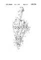
- FIG. 1is a perspective view of the mobile conveyor
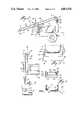
- FIG. 2is a side detail view of the first conveyor
- FIG. 3is a top detail view of the connection of the first conveyor to the chassis
- FIG. 4is a side detail view of the second conveyor and the movable support frame
- FIG. 5is a detail view showing the mounting of the second conveyor lifting means
- FIG. 6is a cross-section view taken along line 6--6 in FIG. 4;
- FIG. 7Ais a detail cross-section view of the second conveyor taken along line 7A--7A in FIG. 4;
- FIG. 7Bis a detail cross-section view of the second conveyor taken along line 7B-7B in FIG. 7A;
- FIG. 8Ais a schematic view of the second conveyor in an extended position
- FIG. 8Bis a schematic view of the second conveyor in a retracted position.
- the mobile conveyor unit 1 of the present inventionhas a chassis 3 mounted on front and rear pairs of wheels 5, 7.
- the rear pair of wheels 5is driven via suitable drive means (not shown), by a motor 9 mounted at the rear of the chassis 3.
- At least the front pair of wheels 7can be steered by suitable steering means (not shown) from an operator's station located at one side, and to the rear, of the chassis 3.
- the mobile conveyor unit 1can thus be easily moved to the desired operating location.
- a first conveyor 13is mounted on the chassis 3 of the conveyor unit 1.
- the first conveyor 13, as shown in FIG. 2,has an elongated, tubular frame 15.
- An endless conveyor belt 17is mounted over rollers 19, 21 located at the ends 23, 25 of the frame 15.
- One of the end rollers 19, 21is driven by motor means (not shown) to move the belt 17 over the rollers so that its upper run 27 can carry goods from the outer end 23 of the conveyor to its inner end 25.
- a plurality of idler rollers 29are mounted on the frame 15 to support the belt 17, particularly the upper run 27 of the belt, between the end rollers 19, 21.
- the first conveyor 13is pivotally mounted at its inner end 25 to an upright, fixed support frame 31.
- the upright support frame 31is fixedly mounted to the chassis 3 near its rear end 33 and carries a pair of horizontally spaced-apart mounting brackets 35 at its upper end 37 as shown in FIG. 3.
- a pair of mounting brackets 39is provided on the frame 15 of the first conveyor 13 adjacent its inner end 25.
- the brackets 39are located under the guide roller 21.
- Horizontal mounting pins 41pass through brackets 35, 39 to pivotally connect the first conveyor 13 to the support frame 31.
- the first conveyor 13is also supported on the chassis 3 by a pair of movable, rigid, supports 43.
- Each support 43preferably comprises a hydraulic actuator 45 having a projecting piston rod 47.
- the actuator 45is pivotally mounted via a pivot pin 49 to a bracket 51 fixed to the chassis 3 at its rear end 33.
- the projecting piston rod 47is pivotally mounted, via a pivot pin 53 to a bracket 55 fixed to the bottom of the conveyor frame 15 at a point spaced from its inner end 25.
- the piston rods 47 of the actuators 45can be extended or withdrawn to raise or lower the first conveyor 13 about the horizontal mounting pin 41. Thus the height of the outer end 23 of the first conveyor 13 can be adjusted to locate it in the desired working position.
- a pair of rigid, rear guide members 57, 59is mounted on the end 33 of the chassis 3 and extends upwardly, one on each side of the first conveyor 13.
- the guide members 57, 59can be braced to the support frame 31 if needed.
- the guide members 57, 59lie closely adjacent to wear bars 61 mounted on the sides of the frame 15 of the first conveyor 13.
- the rear guide members 57, 59guide the first conveyor 13 during its up and down movement, and serve to steady it in its selected position.
- a second conveyor 65is mounted on the chassis 3 of the conveyor unit 1 in a position to cooperate with the first conveyor 13.
- the second conveyor 65has an inner end 67 located adjacent the inner end 25 of the first conveyor 13 as shown in FIG. 4.
- the second conveyor 65extends forwardly of the chassis 3 to have its outer end 69 well clear of the front end 71 of the chassis.
- the second conveyor 65has two, tubular frames 73, 75.
- the tubular frame 75is telescopically mounted within the tubular frame 73.
- the first, larger conveyor frame 73is pivotally mounted at its inner end 67 to a horizontally extending, movable, support frame 77.
- the movable support frame 77has an inner end 79 located adjacent the upright fixed support frame 31.
- a socket 81is centrally located at the bottom, inner end 79 of the frame 77.
- the support frame 77is pivotally mounted, via the socket 81, to a vertical pivot pin 83 centrally fixed to the chassis 3 adjacent support frame 31.
- the support frame 77can swing horizontally about the pivot pin 83.
- the front end 85 of the movable support frame 77is guided for movement along a curved support track 89 mounted on the chassis 3 at its front end 71.
- the track 89is preferably part-circular in shape with its center of curvature located at the vertical axis of the pivot pin 83.
- the track 89extends well past each side of the chassis 3.
- a pair of wheels 91is rotatably mounted on the front end 85 of the frame 77. At least one of the wheels 91 can be driven by a motor (not shown) to move the movable support frame 77 horizontally along the track 89 about the pivot 83. As the support frame 77 swings horizontally about the pivot 83, so does the second conveyor 65 that it carries.
- the movable support frame 77carries an upright support 95 at its inner end 79.
- a pair of horizontally spaced-apart brackets 97is mounted on the upright support 95 at its upper end 99.
- the second conveyor 65has a pair of brackets 101 at its inner end 67 on the first tubular frame 73.
- a horizontal pivot pin 103connects the brackets 97, 101 together thereby pivotally connecting the second conveyor 65 to the movable support frame 77.
- the second conveyor 65can swing up and down about pivot pin 103 relative to the movable support frame 77.
- Means 105are provided for moving the second conveyor 65 up and down about its inner end 67.
- These moving means 105can comprise a pair of hydraulic actuators 107, 109 each having a projecting piston rod 113.
- One actuator 107is vertically located on one side of the first frame 73 of the second conveyor near its mid-point and the other actuator 109 is vertically located on the other side of the first frame 73.
- Means 115are provided for pivotally mounting each of the actuators 107, 109 to the sides of the first frame 73.
- the mounting means 115as shown in FIG. 5, can comprise a pivot pin 117 extending laterally from the actuator 107 and rotatably mounted in a bracked 119 fixed to the frame 73.
- the bracket 119is fixed to the top of a post 121 extending up from the side of the frame 73 at about its center.
- the post 121anchors tensioning members 123, 125 extending up to the top of the post from the ends 67, 127 respectively of the frame 73.
- Actuator 109is attached to the other side of the frame in a similar manner.
- Means 129are also provided for pivotally mounting each of the actuators 107, 109 to the support frame 77.
- the mounting means 129comprise a pivot pin 131 which connects the piston rod 111 of actuator 107 to a bracket 135 on the side of the movable support frame 77.
- Actuator 109is mounted in a similar manner to the other side of the support frame 77.
- Means 139are provided for guiding the second conveyor 65 during its up and down movement.
- the guiding meanscomprise a pair of rigid front guide members 141, 143 fixed to the front end 85 of the movable frame 77 and extending upwardly about the second conveyor 65 adjacent the sides 145, 147 of the first frame 73 as shown in FIGS. 4 and 6. Wear bars 149, 151 on the bottom of the sides 145, 147 of the first frame 73 guide the second conveyor 65 between the guide members 141, 143 during its up and down movement.
- the guide members 141, 143also serve to steady the second conveyor 65.
- the second conveyor 65has the first, elongated, tubular frame 73 mounted on the movable support frame 77 via the pivot pin 103 and the hydraulic actuators 107, 109.
- the second elongated, tubular frame 75is slidably mounted within the first frame 73 by means of a pair of guide channels 155, 157 fixed to the inner surfaces of the side walls 145, 147 of the first frame 73 as shown in FIGS. 7A and 7B.
- a pair of longitudinally spaced-apart, outwardly projecting guide members 163, 165is provided on each side wall 167, 169 of the second frame 75 near its inner end 171.
- the guide members 163, 165slide in the guide channels 155, 157 to slidably mount the second frame 75 within the first frame 73.
- Means 175are provided for moving the second frame 75 relative to the first frame 73.
- These moving means 175, as shown in FIG. 4,can comprise an endless chain 177 running between a first sprocket wheel 179 fixed to the first frame 73 at its rear end 67 and a second sprocket wheel 181 fixed to the first frame 73 at its front end 127.
- the chain 177is linked on a bracket 183 fixed to the side wall 167 of the second frame 75 near its inner end 185.
- Motor means(not shown) operate one of the sprocket wheels 179, When the one sprocket wheel is operated, the chain drive moves the second frame 75 relative to the first frame 65 along the guide channels 155, 157.
- An endless conveyor belt 191is provided on the second conveyor 65.
- the belt 191passes over a first roller 193 on the inner end 67 of the first frame 73 and along the top of the first frame 73 over carrying rollers 195 as shown in FIGS. 8A and 8B.
- the belt 191drops down onto the top of the projecting portion of the second frame 75 running to a second roller 199 at the outer end 69 of the second frame 75 while passing over carrying rollers 203. From the second roller 199, the belt 191 passes back under the second frame 75 to a third roller 205 mounted at the rear end 185 of the second frame 75.
- the beltpasses over a fourth roller 207 mounted at the bottom of the front end 127 of the first frame 73. From fourth roller 207 the belt passes back along the bottom of the first frame 73 to the first roller 193 via any necessary returning rollers 209. At least one of the main rollers 193, 199, 205, 207 is driven by a motor (not shown) to drive the belt 191.
- a second operator's station 213is provided at the outer end of the second frame 73 of the second conveyor 65.
- the second station 213is mounted from the side of the second frame 75 and carries controls allowing an operator at this station to laterally swing, raise or lower, and shorten or lengthen the second conveyor 65 as required.
- This featureis particularly useful piling goods, such as bags of peat, in a huge pile.
- the operator doing the actual piling of the goods delivered by the second conveyorcan keep repositioning the delivery end 69 of the second conveyor in the most convenient unloading positions from the second station 213.
- Either conveyor 13, 65can be operated from the first operator's station Station 213 however operates the second conveyor only.
- the conveyors 13, 65can of course be operated in either direction. It is also contemplated that the first conveyor 13 could also be made in two frame sections, with one frame section slidable within the other frame section so that the conveyor 13 could be extended in a similar manner to the second conveyor 65.
- a third operator's stationcould be provided at the outer end 23 of the first conveyor 13 to raise or lower it, or to extend or retract it if the conveyor is made in two sections. The main operator's station 11 only is used to drive the mobile conveyor unit to or from a job site and to reposition the conveyor unit at the job site.
Landscapes
- Engineering & Computer Science (AREA)
- Mechanical Engineering (AREA)
- Framework For Endless Conveyors (AREA)
- Intermediate Stations On Conveyors (AREA)
Abstract
Description
Claims (12)
Applications Claiming Priority (2)
| Application Number | Priority Date | Filing Date | Title |
|---|---|---|---|
| CA522083 | 1986-11-03 | ||
| CA522083 | 1986-11-03 |
Publications (1)
| Publication Number | Publication Date |
|---|---|
| US4813526Atrue US4813526A (en) | 1989-03-21 |
Family
ID=4134288
Family Applications (1)
| Application Number | Title | Priority Date | Filing Date |
|---|---|---|---|
| US07/113,502Expired - Fee RelatedUS4813526A (en) | 1986-11-03 | 1987-10-28 | Conveyor |
Country Status (1)
| Country | Link |
|---|---|
| US (1) | US4813526A (en) |
Cited By (59)
| Publication number | Priority date | Publication date | Assignee | Title |
|---|---|---|---|---|
| US4981204A (en)* | 1989-11-02 | 1991-01-01 | Smith Roger G | Mobile material-handling apparatus |
| US5074402A (en)* | 1990-12-24 | 1991-12-24 | General Electric Company | Extensible ammunition conveyor |
| US5099634A (en)* | 1986-11-25 | 1992-03-31 | Browntree Trading Company Proprietary Ltd. | Method and means for loading packaged particulate materials |
| US5154036A (en)* | 1990-02-06 | 1992-10-13 | Focke & Co. (Gmbh & Co.) | Process and apparatus for the handling, especially conveyance of blanks |
| US5188208A (en)* | 1991-02-13 | 1993-02-23 | Meco Australia Pty Limited | Belt conveyor advancing and/or retreating return end |
| US5282501A (en)* | 1993-01-29 | 1994-02-01 | Miller Iii George E | Wood processing apparatus |
| AU652414B2 (en)* | 1991-02-13 | 1994-08-25 | Meco Australia Pty Limited | Belt conveyor advancing and/or retreating return end |
| US5351809A (en)* | 1993-04-26 | 1994-10-04 | Rapistan Demag Corporation | Multiple-stage extendable conveyor |
| US5423413A (en)* | 1993-10-01 | 1995-06-13 | Rapistan Demag Corporation | Electrical cable support in extendable conveyor |
| US5429471A (en)* | 1993-02-11 | 1995-07-04 | Ecofina S.R.L. | Apparatus and method for loading automatic machines with objects packed in alternating orientations |
| WO1997031713A1 (en)* | 1996-02-28 | 1997-09-04 | Columbus Mckinnon Corporation | Telescoping infeed conveyor |
| US5697753A (en)* | 1995-09-19 | 1997-12-16 | Recot, Inc. | Semiautomatic stacker for stackable articles |
| US5863174A (en)* | 1995-10-06 | 1999-01-26 | Mola; Enrico | Apparatus for picking up poultry from breeding pens |
| WO1999012834A1 (en) | 1997-09-09 | 1999-03-18 | United Parcel Service Of America, Inc. | Automated array sorter for conveyors |
| WO1999050091A1 (en)* | 1998-04-01 | 1999-10-07 | Putzmeister Ag | Travelling conveyor |
| US5988356A (en)* | 1997-09-08 | 1999-11-23 | United Parcel Service Of America, Inc. | Automated diverter capable of sorting bulky articles |
| US6006921A (en)* | 1998-04-03 | 1999-12-28 | Diamond Z Manufacturing Co., Inc. | Transportable trommel assembly |
| US6006893A (en)* | 1996-04-24 | 1999-12-28 | Mannesmann Dematic Rapistan Corp. | Extendable trailer loader/unloader with user interface section |
| US6116842A (en)* | 1998-10-02 | 2000-09-12 | Harris; Richard D. | Transfer car for a conveyor system |
| WO2001079093A1 (en)* | 2000-04-13 | 2001-10-25 | Turkey Scope, Llc | Livestock loading/unloading system |
| US6332736B1 (en) | 1999-04-08 | 2001-12-25 | James Cape And Sons Company | Method and apparatus for spreading paving materials |
| US6431346B1 (en)* | 1996-04-24 | 2002-08-13 | Rapistan Systems Advertising Corp. | Extendable trailer loader/unloader with user interface section |
| US20020121430A1 (en)* | 2001-01-26 | 2002-09-05 | Roland Grundl | Mobile feeder and mounting device |
| US6447234B2 (en)* | 1997-02-21 | 2002-09-10 | Turkey Scope, Llc | Livestock loading/unloading system |
| US6454510B1 (en)* | 2000-06-17 | 2002-09-24 | Turkey Scope, Llc | Livestock unloading system |
| US6477987B2 (en)* | 2000-04-20 | 2002-11-12 | John S. Taylor | Method and apparatus for relocating live poultry |
| US6484862B1 (en) | 2000-07-18 | 2002-11-26 | Rapistan Systems Advertising Corp. | Extendable gravity loader |
| US20040031662A1 (en)* | 2002-08-14 | 2004-02-19 | Jacoba Dekoning Adrianus Petrus | Telescoping tube conveyor |
| DE10255843A1 (en)* | 2002-11-29 | 2004-06-17 | Caljan Loading-Systems | Telescopic conveyor |
| US6782993B2 (en)* | 2002-01-28 | 2004-08-31 | Terra Nova Technologies, Inc. | Mobile conveyor system and method for multiple lift stacking |
| US20050178090A1 (en)* | 2002-02-27 | 2005-08-18 | John Koke | Vacuum packaging machine |
| US20050258015A1 (en)* | 2003-02-05 | 2005-11-24 | Kinzer Dwight E | Track-and-trolley conveyor guidance system |
| US20060064946A1 (en)* | 1999-10-27 | 2006-03-30 | Cryovac, Inc. | Vacuum packaging machine |
| US7055297B1 (en)* | 1998-10-28 | 2006-06-06 | Cryovac, Inc. | Vacuum packaging machine |
| US20070031227A1 (en)* | 2005-08-05 | 2007-02-08 | Donelson Construction Co.Llc. | Truck mounted bulk material transfer unit |
| US20070102263A1 (en)* | 2005-11-10 | 2007-05-10 | Dieter Hoffmann | Mobile conveying and stacking system for multilayer dumping and process for operating the system |
| WO2008046191A1 (en)* | 2006-10-11 | 2008-04-24 | Pierre Laganiere | Extendable conveyor system |
| US7448486B1 (en) | 2007-08-10 | 2008-11-11 | Masaba, Inc. | Telescoping conveyor drive system |
| US20090074546A1 (en)* | 2005-05-02 | 2009-03-19 | Univeyor A/S | System for unloading or loading of cargo |
| US20090169351A1 (en)* | 2007-12-26 | 2009-07-02 | Kuan-Shiung Wu | Automatic stacking device |
| US20100009731A1 (en)* | 2008-07-09 | 2010-01-14 | Coers Bruce A | Agricultural work machine having an unloading system for unloading an agricultural product |
| US20100012467A1 (en)* | 2008-07-15 | 2010-01-21 | Coers Bruce A | Tractor mounted unloading conveyor |
| CN101955069A (en)* | 2010-05-28 | 2011-01-26 | 四川邓仕机械制造有限公司 | Movable conveyor |
| CN101955068A (en)* | 2010-09-20 | 2011-01-26 | 扬州中欧工业机器人有限公司 | Telescopic bidirectional loading and unloading conveyor |
| US20120090957A1 (en)* | 2010-10-15 | 2012-04-19 | Sanofi-Aventis U.S. Llc | Apparatus and method for loading and unloading containers |
| CN102514905A (en)* | 2011-12-31 | 2012-06-27 | 刘勇 | Conveyor |
| US20120255835A1 (en)* | 2011-04-06 | 2012-10-11 | Precision Automation & Robotics India Ltd. | Cargo handling system |
| CN101624131B (en)* | 2009-07-27 | 2013-05-01 | 四川邓仕机械制造有限公司 | Conveyor |
| US8464859B2 (en) | 2010-10-26 | 2013-06-18 | Engineered Lifting Systems & Equipment Inc. | Conveyor apparatus for unloading packages from shipping containers |
| US8944239B2 (en) | 2010-10-26 | 2015-02-03 | Engineered Lifting Systems & Equipment Inc. | Conveyor apparatus for loading or unloading packages from shipping containers |
| DE102013019688A1 (en)* | 2013-11-26 | 2015-06-11 | Sew-Eurodrive Gmbh & Co Kg | Transport system with vehicle, in particular for transporting a lifting device |
| US9090411B2 (en) | 2010-10-15 | 2015-07-28 | Sanofi-Aventis U.S. Llc | Apparatus and method for loading and unloading containers |
| US20150336747A1 (en)* | 2014-05-23 | 2015-11-26 | Ty-Crop Manufacturing Ltd. | Material Handling Conveyor Vehicle |
| US9428348B2 (en) | 2010-10-21 | 2016-08-30 | Ty-Crop Manufacturing Ltd. | Mobile material handling and metering system |
| US9643789B2 (en) | 2014-06-09 | 2017-05-09 | Ty-Crop Manufacturing Ltd. | Control system for material handling conveyor vehicle |
| US9957108B2 (en) | 2015-06-08 | 2018-05-01 | Continental Intermodal Group-Trucking Llc | Conveyor transition for material handling |
| US10046245B1 (en) | 2016-06-06 | 2018-08-14 | Galaxy America Inc. | Obstacle apparatus and method |
| CN110844471A (en)* | 2019-10-31 | 2020-02-28 | 中船华南船舶机械有限公司 | Telescopic vertical lifting equipment |
| WO2022046139A1 (en)* | 2020-08-31 | 2022-03-03 | Fmh Conveyors Llc | Extendable loader with multiple conveyors |
Citations (5)
| Publication number | Priority date | Publication date | Assignee | Title |
|---|---|---|---|---|
| US2138200A (en)* | 1937-08-04 | 1938-11-29 | William A Whitmire | Mucking machine and conveyer system |
| US2805759A (en)* | 1955-06-21 | 1957-09-10 | Frank E Manceau | Potato elevator |
| US3717263A (en)* | 1971-01-21 | 1973-02-20 | J Mcwilliams | Apparatus for loading bagged mail from a loading dock into a highway vehicle |
| US3825107A (en)* | 1971-07-26 | 1974-07-23 | M Mahacek | Extendible conveyor system |
| US3826353A (en)* | 1972-08-04 | 1974-07-30 | C Greasley | Conveyors |
- 1987
- 1987-10-28USUS07/113,502patent/US4813526A/ennot_activeExpired - Fee Related
Patent Citations (5)
| Publication number | Priority date | Publication date | Assignee | Title |
|---|---|---|---|---|
| US2138200A (en)* | 1937-08-04 | 1938-11-29 | William A Whitmire | Mucking machine and conveyer system |
| US2805759A (en)* | 1955-06-21 | 1957-09-10 | Frank E Manceau | Potato elevator |
| US3717263A (en)* | 1971-01-21 | 1973-02-20 | J Mcwilliams | Apparatus for loading bagged mail from a loading dock into a highway vehicle |
| US3825107A (en)* | 1971-07-26 | 1974-07-23 | M Mahacek | Extendible conveyor system |
| US3826353A (en)* | 1972-08-04 | 1974-07-30 | C Greasley | Conveyors |
Cited By (93)
| Publication number | Priority date | Publication date | Assignee | Title |
|---|---|---|---|---|
| US5099634A (en)* | 1986-11-25 | 1992-03-31 | Browntree Trading Company Proprietary Ltd. | Method and means for loading packaged particulate materials |
| US4981204A (en)* | 1989-11-02 | 1991-01-01 | Smith Roger G | Mobile material-handling apparatus |
| US5154036A (en)* | 1990-02-06 | 1992-10-13 | Focke & Co. (Gmbh & Co.) | Process and apparatus for the handling, especially conveyance of blanks |
| US5074402A (en)* | 1990-12-24 | 1991-12-24 | General Electric Company | Extensible ammunition conveyor |
| EP0492932A3 (en)* | 1990-12-24 | 1993-03-17 | General Electric Company | Conveyor |
| AU652414B2 (en)* | 1991-02-13 | 1994-08-25 | Meco Australia Pty Limited | Belt conveyor advancing and/or retreating return end |
| US5188208A (en)* | 1991-02-13 | 1993-02-23 | Meco Australia Pty Limited | Belt conveyor advancing and/or retreating return end |
| US5282501A (en)* | 1993-01-29 | 1994-02-01 | Miller Iii George E | Wood processing apparatus |
| US5429471A (en)* | 1993-02-11 | 1995-07-04 | Ecofina S.R.L. | Apparatus and method for loading automatic machines with objects packed in alternating orientations |
| US5351809A (en)* | 1993-04-26 | 1994-10-04 | Rapistan Demag Corporation | Multiple-stage extendable conveyor |
| US5423413A (en)* | 1993-10-01 | 1995-06-13 | Rapistan Demag Corporation | Electrical cable support in extendable conveyor |
| US5487462A (en)* | 1993-10-01 | 1996-01-30 | Rapistan Demag Corporation | Extendable conveyor without base unit |
| US5697753A (en)* | 1995-09-19 | 1997-12-16 | Recot, Inc. | Semiautomatic stacker for stackable articles |
| US5863174A (en)* | 1995-10-06 | 1999-01-26 | Mola; Enrico | Apparatus for picking up poultry from breeding pens |
| WO1997031713A1 (en)* | 1996-02-28 | 1997-09-04 | Columbus Mckinnon Corporation | Telescoping infeed conveyor |
| US5669562A (en)* | 1996-02-28 | 1997-09-23 | Columbus Mckinnon Corporation | Telescoping infeed conveyor |
| AU713019B2 (en)* | 1996-02-28 | 1999-11-18 | Columbus Mckinnon Corporation | Telescoping infeed conveyor |
| EP0886545A4 (en)* | 1996-02-28 | 2000-12-20 | Columbus Mckinnon Corp | Telescoping infeed conveyor |
| US6006893A (en)* | 1996-04-24 | 1999-12-28 | Mannesmann Dematic Rapistan Corp. | Extendable trailer loader/unloader with user interface section |
| US6431346B1 (en)* | 1996-04-24 | 2002-08-13 | Rapistan Systems Advertising Corp. | Extendable trailer loader/unloader with user interface section |
| US6823985B2 (en) | 1996-04-24 | 2004-11-30 | Rapistan Systems Advertising Corp. | Extendable trailer loader/unloader with user interface section |
| US6447234B2 (en)* | 1997-02-21 | 2002-09-10 | Turkey Scope, Llc | Livestock loading/unloading system |
| US5988356A (en)* | 1997-09-08 | 1999-11-23 | United Parcel Service Of America, Inc. | Automated diverter capable of sorting bulky articles |
| WO1999012834A1 (en) | 1997-09-09 | 1999-03-18 | United Parcel Service Of America, Inc. | Automated array sorter for conveyors |
| US6227377B1 (en) | 1997-09-09 | 2001-05-08 | United Parcel Service Of America, Inc. | Automated array sorter for conveyors |
| WO1999050091A1 (en)* | 1998-04-01 | 1999-10-07 | Putzmeister Ag | Travelling conveyor |
| US6006921A (en)* | 1998-04-03 | 1999-12-28 | Diamond Z Manufacturing Co., Inc. | Transportable trommel assembly |
| US6116842A (en)* | 1998-10-02 | 2000-09-12 | Harris; Richard D. | Transfer car for a conveyor system |
| US7055297B1 (en)* | 1998-10-28 | 2006-06-06 | Cryovac, Inc. | Vacuum packaging machine |
| US6332736B1 (en) | 1999-04-08 | 2001-12-25 | James Cape And Sons Company | Method and apparatus for spreading paving materials |
| US7228674B2 (en) | 1999-10-27 | 2007-06-12 | Cryovac, Inc. | Vacuum packaging machine |
| US20060064946A1 (en)* | 1999-10-27 | 2006-03-30 | Cryovac, Inc. | Vacuum packaging machine |
| WO2001079093A1 (en)* | 2000-04-13 | 2001-10-25 | Turkey Scope, Llc | Livestock loading/unloading system |
| US6477987B2 (en)* | 2000-04-20 | 2002-11-12 | John S. Taylor | Method and apparatus for relocating live poultry |
| US6454510B1 (en)* | 2000-06-17 | 2002-09-24 | Turkey Scope, Llc | Livestock unloading system |
| US20020154972A1 (en)* | 2000-06-17 | 2002-10-24 | Sinn Steven C. | Livestock unloading system |
| US6484862B1 (en) | 2000-07-18 | 2002-11-26 | Rapistan Systems Advertising Corp. | Extendable gravity loader |
| US6533096B2 (en) | 2000-07-18 | 2003-03-18 | Rapistan Systems Advertising Corp. | Extendable gravity loader |
| US20020121430A1 (en)* | 2001-01-26 | 2002-09-05 | Roland Grundl | Mobile feeder and mounting device |
| US6725996B2 (en)* | 2001-01-26 | 2004-04-27 | Joseph Voegele Ag | Mobile feeder and mounting device |
| US6782993B2 (en)* | 2002-01-28 | 2004-08-31 | Terra Nova Technologies, Inc. | Mobile conveyor system and method for multiple lift stacking |
| US20050178090A1 (en)* | 2002-02-27 | 2005-08-18 | John Koke | Vacuum packaging machine |
| US7296390B2 (en) | 2002-02-27 | 2007-11-20 | Sealed Air New Zealand | Vacuum packaging machine having a plurality of vacuum chambers for performing a vacuum sealing operation on product packages |
| US6805229B2 (en)* | 2002-08-14 | 2004-10-19 | Adrianus Petrus Jacoba Dekoning | Telescoping tube conveyor |
| US20040031662A1 (en)* | 2002-08-14 | 2004-02-19 | Jacoba Dekoning Adrianus Petrus | Telescoping tube conveyor |
| DE10255843B4 (en)* | 2002-11-29 | 2012-06-06 | Caljan Rite-Hite Aps | Telescopic conveyor |
| DE10255843A1 (en)* | 2002-11-29 | 2004-06-17 | Caljan Loading-Systems | Telescopic conveyor |
| US20070031220A1 (en)* | 2003-02-05 | 2007-02-08 | Kinzer Dwight E | Arcuate guide apparatus and method for conveyor(s) |
| US7125215B2 (en)* | 2003-02-05 | 2006-10-24 | Dwight Eric Kinzer | Track-and-trolley conveyor guidance system |
| US20050258015A1 (en)* | 2003-02-05 | 2005-11-24 | Kinzer Dwight E | Track-and-trolley conveyor guidance system |
| US20070031221A1 (en)* | 2003-02-05 | 2007-02-08 | Kinzer Dwight E | Guide apparatus and method for conveyor(s) |
| US7267517B2 (en)* | 2003-02-05 | 2007-09-11 | Dwight Eric Kinzer | Arcuate guide apparatus and method for conveyor(s) |
| US7267518B2 (en)* | 2003-02-05 | 2007-09-11 | Dwight Eric Kinzer | Guide apparatus and method for conveyor(s) |
| US8262334B2 (en)* | 2005-05-02 | 2012-09-11 | Univeyor A/S | System for unloading or loading of cargo |
| US20090074546A1 (en)* | 2005-05-02 | 2009-03-19 | Univeyor A/S | System for unloading or loading of cargo |
| AU2006276216B9 (en)* | 2005-07-27 | 2011-11-03 | Dwight Eric Kinzer | Track-and-trolley conveyor guidance system |
| AU2006276216B2 (en)* | 2005-07-27 | 2011-10-27 | Dwight Eric Kinzer | Track-and-trolley conveyor guidance system |
| US20070031227A1 (en)* | 2005-08-05 | 2007-02-08 | Donelson Construction Co.Llc. | Truck mounted bulk material transfer unit |
| US8033775B2 (en) | 2005-08-05 | 2011-10-11 | Donelson Construction Co., Llc | Truck mounted bulk material transfer unit |
| US7284650B2 (en)* | 2005-11-10 | 2007-10-23 | MAN TAKRAF Fördertechnik GmbH | Mobile conveying and stacking system for multilayer dumping and process for operating the system |
| US20070102263A1 (en)* | 2005-11-10 | 2007-05-10 | Dieter Hoffmann | Mobile conveying and stacking system for multilayer dumping and process for operating the system |
| WO2008046191A1 (en)* | 2006-10-11 | 2008-04-24 | Pierre Laganiere | Extendable conveyor system |
| US7448486B1 (en) | 2007-08-10 | 2008-11-11 | Masaba, Inc. | Telescoping conveyor drive system |
| US20090071797A1 (en)* | 2007-08-10 | 2009-03-19 | Jim Frankl | Telescoping conveyor drive system |
| US7784597B2 (en) | 2007-08-10 | 2010-08-31 | Masaba, Inc. | Telescoping conveyor drive system |
| US20090169351A1 (en)* | 2007-12-26 | 2009-07-02 | Kuan-Shiung Wu | Automatic stacking device |
| US20100009731A1 (en)* | 2008-07-09 | 2010-01-14 | Coers Bruce A | Agricultural work machine having an unloading system for unloading an agricultural product |
| US8398469B2 (en)* | 2008-07-09 | 2013-03-19 | Deere & Company | Agricultural work machine having an unloading system for unloading an agricultural product |
| US8132659B2 (en)* | 2008-07-15 | 2012-03-13 | Deere & Company | Tractor mounted unloading conveyor |
| US20100012467A1 (en)* | 2008-07-15 | 2010-01-21 | Coers Bruce A | Tractor mounted unloading conveyor |
| CN101624131B (en)* | 2009-07-27 | 2013-05-01 | 四川邓仕机械制造有限公司 | Conveyor |
| CN101955069A (en)* | 2010-05-28 | 2011-01-26 | 四川邓仕机械制造有限公司 | Movable conveyor |
| CN101955068B (en)* | 2010-09-20 | 2013-02-27 | 扬州中欧工业机器人有限公司 | Telescopic bidirectional loading and unloading conveyor |
| CN101955068A (en)* | 2010-09-20 | 2011-01-26 | 扬州中欧工业机器人有限公司 | Telescopic bidirectional loading and unloading conveyor |
| US8684652B2 (en)* | 2010-10-15 | 2014-04-01 | Sanofi-Aventis U.S. Llc | Apparatus and method for loading and unloading containers |
| US20120090957A1 (en)* | 2010-10-15 | 2012-04-19 | Sanofi-Aventis U.S. Llc | Apparatus and method for loading and unloading containers |
| US9090411B2 (en) | 2010-10-15 | 2015-07-28 | Sanofi-Aventis U.S. Llc | Apparatus and method for loading and unloading containers |
| US9428348B2 (en) | 2010-10-21 | 2016-08-30 | Ty-Crop Manufacturing Ltd. | Mobile material handling and metering system |
| US8464859B2 (en) | 2010-10-26 | 2013-06-18 | Engineered Lifting Systems & Equipment Inc. | Conveyor apparatus for unloading packages from shipping containers |
| US8944239B2 (en) | 2010-10-26 | 2015-02-03 | Engineered Lifting Systems & Equipment Inc. | Conveyor apparatus for loading or unloading packages from shipping containers |
| US20120255835A1 (en)* | 2011-04-06 | 2012-10-11 | Precision Automation & Robotics India Ltd. | Cargo handling system |
| CN102514905A (en)* | 2011-12-31 | 2012-06-27 | 刘勇 | Conveyor |
| DE102013019688A1 (en)* | 2013-11-26 | 2015-06-11 | Sew-Eurodrive Gmbh & Co Kg | Transport system with vehicle, in particular for transporting a lifting device |
| DE102013019688B4 (en) | 2013-11-26 | 2022-05-05 | Sew-Eurodrive Gmbh & Co Kg | Transport system with vehicle for transporting a load handling device |
| US9334124B2 (en) | 2014-05-23 | 2016-05-10 | Ty-Crop Manufacturing Ltd. | Material handling conveyor vehicle |
| US9499348B2 (en)* | 2014-05-23 | 2016-11-22 | Ty-Crop Manufacturing Ltd. | Material handling conveyor vehicle |
| US20150336747A1 (en)* | 2014-05-23 | 2015-11-26 | Ty-Crop Manufacturing Ltd. | Material Handling Conveyor Vehicle |
| US9643789B2 (en) | 2014-06-09 | 2017-05-09 | Ty-Crop Manufacturing Ltd. | Control system for material handling conveyor vehicle |
| US9957108B2 (en) | 2015-06-08 | 2018-05-01 | Continental Intermodal Group-Trucking Llc | Conveyor transition for material handling |
| US10046245B1 (en) | 2016-06-06 | 2018-08-14 | Galaxy America Inc. | Obstacle apparatus and method |
| CN110844471A (en)* | 2019-10-31 | 2020-02-28 | 中船华南船舶机械有限公司 | Telescopic vertical lifting equipment |
| WO2022046139A1 (en)* | 2020-08-31 | 2022-03-03 | Fmh Conveyors Llc | Extendable loader with multiple conveyors |
| US11718481B2 (en) | 2020-08-31 | 2023-08-08 | Fmh Conveyors Llc | Extendable loader with multiple conveyors |
Similar Documents
| Publication | Publication Date | Title |
|---|---|---|
| US4813526A (en) | Conveyor | |
| US5718325A (en) | Adjustable conveyor system for man-loaded cargos | |
| US3945484A (en) | Single belt, multiple conveyor system | |
| US5299674A (en) | Conveyor system and method employing a mobile belt support structure | |
| US3527313A (en) | Apparatus for walking ground-working machinery | |
| US4523669A (en) | Retractable conveyor belt | |
| US3687276A (en) | Self-propelled conveyor apparatus | |
| US5088873A (en) | Manipulator mixed freight handling system | |
| CA2004664A1 (en) | Mixed freight handling system | |
| CA1199627A (en) | Pipe pickup and laydown machine | |
| US3817401A (en) | Self-propelled dual-jack hoist | |
| JP4037669B2 (en) | Truck loader and installation method | |
| JPH01117199A (en) | Carrier truck assembly for extensible boom machine | |
| US4557368A (en) | Field crop harvesting and packing machine | |
| CN109720776A (en) | A kind of telescopic inverted arch trestle belt trolley | |
| US2751095A (en) | Hydraulically operated load handling system for trucks | |
| EP0837018B1 (en) | Continuous unloader | |
| US3437174A (en) | Mobile platform construction | |
| US3602385A (en) | Fork lifting apparatus | |
| US3539067A (en) | Vehicle for loading and unloading bales of hay and like articles | |
| US5131798A (en) | Railroad car conveyor | |
| JPH09100011A (en) | Adjustable type conveyor system by which person loads or unloads freight | |
| US7798344B2 (en) | Tarping system | |
| CN210972650U (en) | Movable folding belt conveyor | |
| US3045850A (en) | Dual fork lift attachment |
Legal Events
| Date | Code | Title | Description |
|---|---|---|---|
| AS | Assignment | Owner name:ENTERPRISES PREMIER CDN LTEE., 454 CHEMIN TEMICOUA Free format text:ASSIGNMENT OF ASSIGNORS INTEREST.;ASSIGNOR:BELANGER, BERNARD;REEL/FRAME:004913/0416 Effective date:19880609 Owner name:ENTERPRISES PREMIER CDN LTEE.,CANADA Free format text:ASSIGNMENT OF ASSIGNORS INTEREST;ASSIGNOR:BELANGER, BERNARD;REEL/FRAME:004913/0416 Effective date:19880609 | |
| FEPP | Fee payment procedure | Free format text:PAYOR NUMBER ASSIGNED (ORIGINAL EVENT CODE: ASPN); ENTITY STATUS OF PATENT OWNER: SMALL ENTITY | |
| FEPP | Fee payment procedure | Free format text:PAYOR NUMBER ASSIGNED (ORIGINAL EVENT CODE: ASPN); ENTITY STATUS OF PATENT OWNER: SMALL ENTITY Free format text:PAYER NUMBER DE-ASSIGNED (ORIGINAL EVENT CODE: RMPN); ENTITY STATUS OF PATENT OWNER: SMALL ENTITY | |
| FPAY | Fee payment | Year of fee payment:4 | |
| REMI | Maintenance fee reminder mailed | ||
| LAPS | Lapse for failure to pay maintenance fees | ||
| FP | Lapsed due to failure to pay maintenance fee | Effective date:19970326 | |
| STCH | Information on status: patent discontinuation | Free format text:PATENT EXPIRED DUE TO NONPAYMENT OF MAINTENANCE FEES UNDER 37 CFR 1.362 |