US4813434A - Steerable guidewire with deflectable tip - Google Patents
Steerable guidewire with deflectable tipDownload PDFInfo
- Publication number
- US4813434A US4813434AUS07/175,099US17509988AUS4813434AUS 4813434 AUS4813434 AUS 4813434AUS 17509988 AUS17509988 AUS 17509988AUS 4813434 AUS4813434 AUS 4813434A
- Authority
- US
- United States
- Prior art keywords
- spring coil
- proximal
- guidewire
- distal end
- wire
- Prior art date
- Legal status (The legal status is an assumption and is not a legal conclusion. Google has not performed a legal analysis and makes no representation as to the accuracy of the status listed.)
- Expired - Lifetime
Links
- 229910000679solderInorganic materials0.000claimsdescription12
- 238000000576coating methodMethods0.000claimsdescription6
- 239000011248coating agentSubstances0.000claimsdescription5
- 229910001220stainless steelInorganic materials0.000description5
- 239000010935stainless steelSubstances0.000description4
- 239000004830Super GlueSubstances0.000description3
- FGBJXOREULPLGL-UHFFFAOYSA-Nethyl cyanoacrylateChemical compoundCCOC(=O)C(=C)C#NFGBJXOREULPLGL-UHFFFAOYSA-N0.000description3
- 230000037431insertionEffects0.000description3
- 238000003780insertionMethods0.000description3
- 229910052751metalInorganic materials0.000description3
- 239000002184metalSubstances0.000description3
- 239000000853adhesiveSubstances0.000description2
- 230000001070adhesive effectEffects0.000description2
- 238000010276constructionMethods0.000description2
- 239000004429CalibreSubstances0.000description1
- 229910001260Pt alloyInorganic materials0.000description1
- 229920006362Teflon®Polymers0.000description1
- 238000005219brazingMethods0.000description1
- 230000002526effect on cardiovascular systemEffects0.000description1
- 239000000017hydrogelSubstances0.000description1
- 239000000463materialSubstances0.000description1
- 239000004033plasticSubstances0.000description1
- 229920003023plasticPolymers0.000description1
- 229920000098polyolefinPolymers0.000description1
- -1polytetrafluoroethylenePolymers0.000description1
- 229920001343polytetrafluoroethylenePolymers0.000description1
- 239000004810polytetrafluoroethyleneSubstances0.000description1
- 229920000915polyvinyl chloridePolymers0.000description1
- 239000004800polyvinyl chlorideSubstances0.000description1
- 238000005476solderingMethods0.000description1
- 239000000126substanceSubstances0.000description1
- WFKWXMTUELFFGS-UHFFFAOYSA-NtungstenChemical compound[W]WFKWXMTUELFFGS-UHFFFAOYSA-N0.000description1
- 229910052721tungstenInorganic materials0.000description1
- 239000010937tungstenSubstances0.000description1
- 238000003466weldingMethods0.000description1
- 238000004804windingMethods0.000description1
Images


Classifications
- A—HUMAN NECESSITIES
- A61—MEDICAL OR VETERINARY SCIENCE; HYGIENE
- A61B—DIAGNOSIS; SURGERY; IDENTIFICATION
- A61B1/00—Instruments for performing medical examinations of the interior of cavities or tubes of the body by visual or photographical inspection, e.g. endoscopes; Illuminating arrangements therefor
- A61B1/005—Flexible endoscopes
- A61B1/0051—Flexible endoscopes with controlled bending of insertion part
- A61B1/0057—Constructional details of force transmission elements, e.g. control wires
- A—HUMAN NECESSITIES
- A61—MEDICAL OR VETERINARY SCIENCE; HYGIENE
- A61B—DIAGNOSIS; SURGERY; IDENTIFICATION
- A61B1/00—Instruments for performing medical examinations of the interior of cavities or tubes of the body by visual or photographical inspection, e.g. endoscopes; Illuminating arrangements therefor
- A61B1/005—Flexible endoscopes
- A61B1/01—Guiding arrangements therefore
- A—HUMAN NECESSITIES
- A61—MEDICAL OR VETERINARY SCIENCE; HYGIENE
- A61M—DEVICES FOR INTRODUCING MEDIA INTO, OR ONTO, THE BODY; DEVICES FOR TRANSDUCING BODY MEDIA OR FOR TAKING MEDIA FROM THE BODY; DEVICES FOR PRODUCING OR ENDING SLEEP OR STUPOR
- A61M25/00—Catheters; Hollow probes
- A61M25/01—Introducing, guiding, advancing, emplacing or holding catheters
- A61M25/0105—Steering means as part of the catheter or advancing means; Markers for positioning
- A61M25/0133—Tip steering devices
- A61M25/0136—Handles therefor
- A—HUMAN NECESSITIES
- A61—MEDICAL OR VETERINARY SCIENCE; HYGIENE
- A61M—DEVICES FOR INTRODUCING MEDIA INTO, OR ONTO, THE BODY; DEVICES FOR TRANSDUCING BODY MEDIA OR FOR TAKING MEDIA FROM THE BODY; DEVICES FOR PRODUCING OR ENDING SLEEP OR STUPOR
- A61M25/00—Catheters; Hollow probes
- A61M25/01—Introducing, guiding, advancing, emplacing or holding catheters
- A61M25/09—Guide wires
- A61M25/09016—Guide wires with mandrils
- A61M25/09033—Guide wires with mandrils with fixed mandrils, e.g. mandrils fixed to tip; Tensionable wires
- A—HUMAN NECESSITIES
- A61—MEDICAL OR VETERINARY SCIENCE; HYGIENE
- A61M—DEVICES FOR INTRODUCING MEDIA INTO, OR ONTO, THE BODY; DEVICES FOR TRANSDUCING BODY MEDIA OR FOR TAKING MEDIA FROM THE BODY; DEVICES FOR PRODUCING OR ENDING SLEEP OR STUPOR
- A61M25/00—Catheters; Hollow probes
- A61M25/01—Introducing, guiding, advancing, emplacing or holding catheters
- A61M25/09—Guide wires
- A61M25/09041—Mechanisms for insertion of guide wires
- A—HUMAN NECESSITIES
- A61—MEDICAL OR VETERINARY SCIENCE; HYGIENE
- A61B—DIAGNOSIS; SURGERY; IDENTIFICATION
- A61B17/00—Surgical instruments, devices or methods
- A61B17/22—Implements for squeezing-off ulcers or the like on inner organs of the body; Implements for scraping-out cavities of body organs, e.g. bones; for invasive removal or destruction of calculus using mechanical vibrations; for removing obstructions in blood vessels, not otherwise provided for
- A61B2017/22001—Angioplasty, e.g. PCTA
- A—HUMAN NECESSITIES
- A61—MEDICAL OR VETERINARY SCIENCE; HYGIENE
- A61M—DEVICES FOR INTRODUCING MEDIA INTO, OR ONTO, THE BODY; DEVICES FOR TRANSDUCING BODY MEDIA OR FOR TAKING MEDIA FROM THE BODY; DEVICES FOR PRODUCING OR ENDING SLEEP OR STUPOR
- A61M25/00—Catheters; Hollow probes
- A61M25/01—Introducing, guiding, advancing, emplacing or holding catheters
- A61M25/09—Guide wires
- A61M2025/09175—Guide wires having specific characteristics at the distal tip
Definitions
- the present inventionis directed to a steerable guidewire. More particularly, the invention is directed to a steerable guidewire having enhanced steerability due to rotational control combined with a deflectable tip, which guidewire is suitable for use connection with the insertion of a catheter into a vessel of the body.
- Coil spring guides or guidewireshave been widely used for facilitating the insertion of a catheter into a vessel in the body.
- a coil spring guide with a rounded tipis inserted into a vessel, a catheter is slipped about the coil spring guide until the catheter is in place, and then the guide is retracted from the vessel.
- a coil spring guideis first inserted into a catheter with the rounded tip of the guide extending beyond the distal end of the catheter. Then, this assembly is inserted into a vessel with the rounded tip of the coil spring guide facilitating placement of the guide and catheter tubing in the vessel without puncturing of the vessel. Once in place, the coil spring guide may be retracted, leaving the catheter in the vessel.
- a helically wound flexible spring coilhaving proximal and distal ends, the proximal end of said spring coil being attached to the flexible tubing and the distal end of said spring coil comprising stretched coils
- deflection wireextending through the flexible tubing and spring coil, said deflection wire having proximal and distal ends, and
- a rounded tipattached to the distal end of the spring coil and the distal end of the deflection wire.
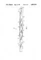
- FIG. 1represents a substantially cross-sectional view of the distal portion of an embodiment of the invention
- FIG. 2represents a substantially cross-sectional view of the distal portion of another embodiment of the invention.
- FIG. 3represents a substantially cross-sectional view of the distal portion of a further embodiment of the invention.
- FIGS. 4 and 5each represent a detail of the tubing shown in FIG. 3;
- FIG. 6represents a cross-sectional view of the proximal portion of an embodiment of the invention.
- the invention hereincomprises a guidewire having improved steerability.
- Steeringis provided by a steering or control wire, i.e., a deflection wire, in conjunction with tubing having a spring coil distal portion.
- the proximal end of the tubingis attached to a control means in which the deflection wire is engaged in a deflection knob assembly.
- Rotation of the deflection knobcauses movement of the deflection wire in an axial direction, which causes the distal end of the guidewire to move toward or away from its longitudinal axis.
- rotation of the control means or a member of the control means attached to the tubing and deflection wireresults in torque being applied to the entire guidewire assembly, and the torque is transmitted to the distal end of the guidewire to cause desired rotation of the guidewire tip.
- the combination of deflection and rotation according to the inventionresults in enhanced steerability.
- Applicants' inventionis directed to a guidewire comprised of flexible tubing having proximal and distal ends and inner and outer surfaces, a helically wound flexible spring coil having proximal and distal ends, said spring coil being attached to the distal end of the flexible tubing, optionally at the proximal end of said spring coil, and the distal end of said spring coil comprising coils having a looser wound, i.e., stretched coils.
- a deflection wireextends through the flexible tubing and spring coil, said deflection wire having proximal and distal ends, and an optional control or safety wire has proximal and distal ends, the proximal end of the control wire being attached to said spring coil proximal to the stretched coils.
- a rounded tipengage the distal end of the spring coil, the distal end of the deflection wire, and the distal end of the control wire.
- the stretched coils of the spring coilthat is, where the tension of the winding of the spring coil body is reduced to form "looser wound” coils, are extremely functional in that they facilitate deflection of the guidewire tip.
- the distal portion of the deflection wiremay be untapered or, advantageously, tapered, the tapering functioning to facilitate deflection.
- a tapered distal portionis flat.
- Applicants' guidewirecomprises tubing, preferably flexible metal tubing such as is used in a hypodermic needle, and a spring coil.
- the distal end of the tubingmust be suitably attached to the spring coil in such a manner to form a continuous lumen for the deflection wire.
- the distal portion of the tubingis concentrically tapered and then angularly tapered to a point, the point being attached to the spring coil.
- the distal end of the spring coilhas a rounded tip, and the proximal end of the guidewire is attached to a control means.
- a guidewire 1comprises tubing 2 having deflection wire 3 arranged axially therein.
- the distal end 4 of tubing 2is recessed to provide a receptacle 5 for the proximal end 6 of spring coil 7.
- the distal end 8 of spring coil 7comprises a cap or tip 9, which is rounded, preferably semi-spherical, in shape.
- Tip 9is formed by a weld, a braze, solder, or an adhesive such as U.V. curing or cyanoacrylate adhesive.
- the coils of spring coil 7 proximal to distal end 8are stretched as compared to the coils in the remainder of spring coil 7.
- the stretched coils 10extend from distal end 8 to adhesion point 11.
- a control wire 12extends from adhesion point 11 to tip 9.
- stretched coils 10are comprised of a radiopaque material such as platinum alloy or the like.
- Proximal end 6 of spring coil 7is affixed, preferably welded, brazed, or soldered, to receptacle 5 at adhesion point 15.
- adhesion point 11comprises a weld, braze, or solder point encompassing the proximal end of control wire 12.
- Deflection wire 3is tapered in its distal portion 13, preferably to a point, or substantially a point, at its distal end 14.
- the taperingwhich begins at about the distal end 4 of the tubing 2, can be linear, stepped, or otherwise non-linear.
- guidewire 20comprises tubing 21 and spring coil 22.
- the distal portion 24 of tubing 21is recessed such that the proximal portion 25 of spring coil 22 fits thereover.
- the proximal portion 25 of spring coil 22is affixed to tubing 21, preferably by welding, brazing, or soldering, at adhesion point 26.
- Deflection wire 23is tapered at its distal end.
- Preferably said tapered portionis substantially flat.
- the coils of spring coil 22 proximal to distal end 27comprise stretched coils 28, which extend from distal end 27 to adhesion point 29.
- a control wire 30is located within said stretched coils, and the proximal end of control wire 30 is affixed at adhesion point 29.
- the distal end 27 of stretched coils 28, the distal end of control wire 30, and the distal end of deflection wire 23are engaged by cap or tip 31.
- distal portion 24 of tubing 21is shown as an integral member of tubing 21. It is within the scope of this invention that distal portion 24 could comprise a separate section of tubing suitably bonded or affixed to tubing 21. Also, the control wire 12 or 30 shown in FIGS. 1 and 2 is optional If this member is not present, there still may or may not be an adhesion point 11 or 29 located at the proximal end of the stretched coils 10 or 28, respectively.
- Guidewire 40comprises tubing 41 having deflection wire 42 arranged axially therein.
- the distal portion 43 of tubing 41is tapered, preferably, in successively, concentrically tapered sections wherein the diameter of the tubing 41 is reduced.
- the distal end 44 of tubing 41is angularly tapered to a point, which can be seen more clearly in FIGS. 4 and 5.
- the proximal portion of spring coil 45is attached to tubing 41 at adhesion point 46.
- the distal end 47 of spring coil 45comprises tip 48, which is rounded, preferably semispherical, in shape. Tip 48 is formed by a weld, a braze, solder, or an adhesive such as U.V. curing or cyanoacrylate adhesive.
- the coils of spring coil 45 proximal to distal end 47are stretched as compared to the coils in the remainder of spring coil 45.
- the stretched coils 49extend from about 1 to 15 cm, preferably from about 2 to 12 cm, from distal end 47.
- Distal end 44 of tubing 41is attached, preferably welded, brazed, or soldered, to the interior surface of stretched coils 49 at adhesion point 50.
- adhesion point 46comprises a weld, braze, or solder point encompassing the proximal end of spring coil 45.
- FIGS. 4 and 5the configuration or shape of the distal end 44 of the tubing can be seen in two different views.
- the distal portion of tubing 41has been shaped, preferably ground, to provide a point 51.
- the catheter guidewire according to the inventionterminates in a control means such as is shown in FIG. 6.
- Said control means 60comprises a tip rotation knob 61 and a tip deflection knob 62.
- the distal portion of tip rotation knob 61is bonded by suitable bonding means, such as a cyanoacrylate adhesive, to the outer surface of guidewire tubing 63.
- suitable bonding meanssuch as a cyanoacrylate adhesive
- the proximal portion of tubing 63terminates within the distal portion of tip rotation knob 61.
- the distal end of a deflection wire 64terminates within, and is engaged by, a deflection member 65.
- deflection member 65has threads 66, and the interior surface of the distal end of tip deflection knob 62 has corresponding threads 67.
- Axial motion of tip deflection knob 62is restrained by annular projection 68.
- deflection member 65is caused to move in an axial direction, that is, either proximally or distally, and deflection wire 64 moves similarly in axial motion relative to tubing 63. Said movement causes the distal end of the guidewire to deflect either toward or away from its longitudinal axis.
- Rotation of tip rotation knob 61causes tubing 63 and deflection wire 64 to rotate together to cause the distal end of the guidewire to rotate.
- the tubingis metal tubing such as stainless steel hypodermic needle tubing having an o.d. of from about 0.010 to 0.040 inch, more preferably from about 0.012 to 0.020 inch, and an i.d. of from about 0.003 to 0.033 inch, more preferably from about 0.005 to 0.017 inch.
- the tubingis successively tapered, advantageously by grinding, distally from a point proximal to the distal end of the spring coil.
- the tubingis ground to dimensions small enough to fit within the spring coil and then, in the distal portion of the tubing, to a "point". For example, the o.d.
- the tubing within the spring coilmay be from about 0.006 to 0.030 inch, preferably from about 0.008 to 0.020 inch, and the distal end of the tubing may be linearly tapered to a point having a thickness of from about 0.0003 to 0.002 inch, preferably from about 0.0007 to 0.0017 inch.
- the linear distance from the initial angular taper to the pointwill be from about 1 to 15 cm, preferably from about 2 to 12 cm.
- Spring coil 7, 22, or 45may be comprised of flat or round metal wire and may comprise one continuous coil or two or more, preferably two, coil sections that are joined together.
- the spring coilis comprised of stainless steel round or rectangular wire and has an o.d. of from about 0.008 to 0.035 inch, preferably from about 0.010 to 0.018 inch.
- Such wiremay have, for example, a cross-sectional width of from about 0.0005 to 0.005 inch, preferably from about 0.001 to 0.004 inch, and a cross-sectional length of from about 0.002 to 0.013 inch, preferably from about 0.003 to 0.012 inch.
- the total length of the guidewireis from about 100 to 190 cm, preferably from about 160 to 180 cm, of which the spring coil comprises from about 25 to 35 cm, more preferably about 30 cm.
- the stretched coilscomprise from about 1 to 10 cm, preferably from about 2 to 8 cm, of the spring coil.
- the control wirewhich is from about 2 to 15 cm in length, preferably comprises small calibre flat tungsten or stainless steel ribbon, having a substantially rectangular cross-section.
- Suitable wiresinclude a flat stainless steel ribbon having dimensions of from 0.0005 to 0.003 inch ⁇ 0.002 to 0.004 inch, more preferably about 0.001 inch ⁇ 0.003 inch.
- the deflection wirewhich extends the length of the guidewire, preferably comprises a stainless steel wire having an o.d. of from about 0.003 to 0.016 inch, more preferably from about 0.005 to 0.012 inch.
- the distal portion of the deflection wireis advantageously tapered for flexibility, said tapering preferably starting approximately at the distal portion of the tubing.
- the taperingcan either be constant or stepped to the extent that the distal end of the deflection wire comprises a "point" of either sharp or flattened shape, having a diameter or effective diameter of from about 0.0003 to 0.003 inch, preferably from about 0.0007 to 0.0017 inch.
- the entire length of the guidewire, optionally including the tipbe coated with a lubricous coating.
- a lubricous coatingexamples include polyolefins, a polytetrafluoroethylene, such as is available as TEFLON® from du Pont, as well as hydrogels, polyvinyl chloride, or other suitable plastic or polymeric substances having low friction surfaces.
Landscapes
- Health & Medical Sciences (AREA)
- Life Sciences & Earth Sciences (AREA)
- Public Health (AREA)
- Biophysics (AREA)
- Engineering & Computer Science (AREA)
- Biomedical Technology (AREA)
- Heart & Thoracic Surgery (AREA)
- Veterinary Medicine (AREA)
- Animal Behavior & Ethology (AREA)
- General Health & Medical Sciences (AREA)
- Surgery (AREA)
- Anesthesiology (AREA)
- Hematology (AREA)
- Pulmonology (AREA)
- Physics & Mathematics (AREA)
- Nuclear Medicine, Radiotherapy & Molecular Imaging (AREA)
- Optics & Photonics (AREA)
- Pathology (AREA)
- Radiology & Medical Imaging (AREA)
- Medical Informatics (AREA)
- Molecular Biology (AREA)
- Media Introduction/Drainage Providing Device (AREA)
Abstract
Description
Claims (20)
Priority Applications (1)
| Application Number | Priority Date | Filing Date | Title |
|---|---|---|---|
| US07/175,099US4813434A (en) | 1987-02-17 | 1988-03-31 | Steerable guidewire with deflectable tip |
Applications Claiming Priority (2)
| Application Number | Priority Date | Filing Date | Title |
|---|---|---|---|
| US07/015,249US4757827A (en) | 1987-02-17 | 1987-02-17 | Steerable guidewire with deflectable tip |
| US07/175,099US4813434A (en) | 1987-02-17 | 1988-03-31 | Steerable guidewire with deflectable tip |
Related Parent Applications (1)
| Application Number | Title | Priority Date | Filing Date |
|---|---|---|---|
| US07/015,249DivisionUS4757827A (en) | 1987-02-17 | 1987-02-17 | Steerable guidewire with deflectable tip |
Publications (1)
| Publication Number | Publication Date |
|---|---|
| US4813434Atrue US4813434A (en) | 1989-03-21 |
Family
ID=26687137
Family Applications (1)
| Application Number | Title | Priority Date | Filing Date |
|---|---|---|---|
| US07/175,099Expired - LifetimeUS4813434A (en) | 1987-02-17 | 1988-03-31 | Steerable guidewire with deflectable tip |
Country Status (1)
| Country | Link |
|---|---|
| US (1) | US4813434A (en) |
Cited By (88)
| Publication number | Priority date | Publication date | Assignee | Title |
|---|---|---|---|---|
| US4940062A (en)* | 1988-05-26 | 1990-07-10 | Advanced Cardiovascular Systems, Inc. | Guiding member with deflectable tip |
| EP0399660A1 (en)* | 1989-05-24 | 1990-11-28 | C.R. Bard, Inc. | Hot tip device with optical diagnostic capability |
| US4998916A (en)* | 1989-01-09 | 1991-03-12 | Hammerslag Julius G | Steerable medical device |
| US5037391A (en)* | 1989-01-09 | 1991-08-06 | Pilot Cardiovascular Systems, Inc. | Steerable angioplasty device |
| US5069217A (en)* | 1990-07-09 | 1991-12-03 | Lake Region Manufacturing Co., Inc. | Steerable guide wire |
| US5069226A (en)* | 1989-04-28 | 1991-12-03 | Tokin Corporation | Catheter guidewire with pseudo elastic shape memory alloy |
| US5108368A (en)* | 1990-01-04 | 1992-04-28 | Pilot Cardiovascular System, Inc. | Steerable medical device |
| US5147317A (en)* | 1990-06-04 | 1992-09-15 | C.R. Bard, Inc. | Low friction varied radiopacity guidewire |
| US5203772A (en)* | 1989-01-09 | 1993-04-20 | Pilot Cardiovascular Systems, Inc. | Steerable medical device |
| US5259393A (en)* | 1992-05-13 | 1993-11-09 | Cordis Corporation | Guidewire having controlled radiopacity tip |
| US5308324A (en)* | 1989-01-09 | 1994-05-03 | Pilot Cardiovascular Systems, Inc. | Steerable medical device |
| US5315747A (en)* | 1992-10-30 | 1994-05-31 | Pameda N.V. | Method of preparing a balloon dilatation catheter |
| WO1994015524A1 (en)* | 1991-11-08 | 1994-07-21 | Electro-Catheter Corporation | Tip deflectable steerable catheter |
| US5333620A (en)* | 1991-10-30 | 1994-08-02 | C. R. Bard, Inc. | High performance plastic coated medical guidewire |
| US5344399A (en)* | 1992-05-26 | 1994-09-06 | Dlp, Inc. | Dual flexible introducer and cannula |
| US5345945A (en)* | 1990-08-29 | 1994-09-13 | Baxter International Inc. | Dual coil guidewire with radiopaque distal tip |
| US5353808A (en)* | 1992-03-04 | 1994-10-11 | Cordis Corporation | Guidewire having distally located marker segment |
| US5377690A (en)* | 1993-02-09 | 1995-01-03 | C. R. Bard, Inc. | Guidewire with round forming wire |
| US5396902A (en)* | 1993-02-03 | 1995-03-14 | Medtronic, Inc. | Steerable stylet and manipulative handle assembly |
| US5402799A (en)* | 1993-06-29 | 1995-04-04 | Cordis Corporation | Guidewire having flexible floppy tip |
| US5407432A (en)* | 1992-03-30 | 1995-04-18 | Pameda N.V. | Method of positioning a stent |
| US5433200A (en)* | 1990-07-09 | 1995-07-18 | Lake Region Manufacturing, Inc. | Low profile, coated, steerable guide wire |
| US5474537A (en)* | 1992-03-30 | 1995-12-12 | Pameda N.V. | Inflatable shaft catheter |
| US5480382A (en)* | 1989-01-09 | 1996-01-02 | Pilot Cardiovascular Systems, Inc. | Steerable medical device |
| US5488959A (en)* | 1993-12-27 | 1996-02-06 | Cordis Corporation | Medical guidewire and welding process |
| US5497783A (en)* | 1994-05-18 | 1996-03-12 | Scimed Life Systems, Inc. | Guidewire having radioscopic tip |
| WO1996015819A1 (en)* | 1994-11-23 | 1996-05-30 | Navarre Biomedical, Ltd. | Flexible catheter |
| US5531690A (en)* | 1992-10-30 | 1996-07-02 | Cordis Corporation | Rapid exchange catheter |
| US5611777A (en)* | 1993-05-14 | 1997-03-18 | C.R. Bard, Inc. | Steerable electrode catheter |
| US5662119A (en)* | 1991-08-28 | 1997-09-02 | Medtronic Inc. | Steerable stylet and manipulative handle assembly |
| US5797856A (en)* | 1995-01-05 | 1998-08-25 | Cardiometrics, Inc. | Intravascular guide wire and method |
| US5810790A (en) | 1996-11-19 | 1998-09-22 | Ebling; Wendell V. | Catheter with viewing system and port connector |
| USRE36628E (en)* | 1987-01-07 | 2000-03-28 | Terumo Kabushiki Kaisha | Method of manufacturing a differentially heat treated catheter guide wire |
| US6132388A (en)* | 1997-10-16 | 2000-10-17 | Scimed Life Systems, Inc. | Guide wire tip |
| WO2001072368A3 (en)* | 2000-03-31 | 2002-05-16 | Medtronic Inc | Intralumenal visualization system with deflectable mechanism |
| US6390992B1 (en)* | 1995-05-05 | 2002-05-21 | Advanced Cardiovascular Systems, Inc. | Intraluminal device with lubricious surface |
| US20030069520A1 (en)* | 2001-10-05 | 2003-04-10 | Scimed Life Systems, Inc. | Guidewire with stiffness blending connection |
| US6575920B2 (en)* | 2001-05-30 | 2003-06-10 | Scimed Life Systems, Inc. | Distal tip portion for a guide wire |
| EP1346747A2 (en) | 2002-03-22 | 2003-09-24 | Cordis Corporation | Guidewire with deflectable tip |
| US6673025B1 (en) | 1993-12-01 | 2004-01-06 | Advanced Cardiovascular Systems, Inc. | Polymer coated guidewire |
| US20040024413A1 (en)* | 2002-07-31 | 2004-02-05 | Lentz David J. | Wire reinforced articulation segment |
| US20040034365A1 (en)* | 2002-08-16 | 2004-02-19 | Lentz David J. | Catheter having articulation system |
| US20040082881A1 (en)* | 2002-03-22 | 2004-04-29 | David Grewe | Guidewire with deflectable tip having improved torque characteristics |
| US6733500B2 (en) | 2000-03-31 | 2004-05-11 | Medtronic, Inc. | Method and system for delivering a medical electrical lead within a venous system |
| US20040106897A1 (en)* | 1990-02-02 | 2004-06-03 | Thompson Russell B. | Assemblies for creating compound curves in distal catheter regions |
| US20040106878A1 (en)* | 2002-12-03 | 2004-06-03 | Scimed Life Systems, Inc. | Composite medical device with markers |
| US20040143239A1 (en)* | 2003-01-17 | 2004-07-22 | Scimed Life Systems, Inc. | Unbalanced reinforcement members for medical device |
| US20040167441A1 (en)* | 2003-02-26 | 2004-08-26 | Reynolds Brian R. | Composite medical device |
| US20040193205A1 (en)* | 2002-03-22 | 2004-09-30 | Robert Burgermeister | Steerable balloon catheter |
| US6836687B2 (en) | 2000-03-31 | 2004-12-28 | Medtronic, Inc. | Method and system for delivery of a medical electrical lead within a venous system |
| US20050065456A1 (en)* | 2003-09-22 | 2005-03-24 | Scimed Life Systems, Inc. | Guidewire with reinforcing member |
| US20050119644A1 (en)* | 2003-12-01 | 2005-06-02 | Koerner Richard J. | Articulating catheter tip with wedge-cuts |
| US6926711B2 (en) | 2003-07-30 | 2005-08-09 | Cryocor, Inc. | Articulating catheter for cryoablation with reduced diameter section |
| US20050177132A1 (en)* | 2004-02-09 | 2005-08-11 | Lentz David J. | Catheter articulation segment with alternating cuts |
| US20050177131A1 (en)* | 2004-02-09 | 2005-08-11 | Lentz David J. | Catheter articulation segment with alternating cuts |
| DE102004003082A1 (en)* | 2004-01-21 | 2005-08-18 | Siemens Ag | Catheter for insertion into vessel, comprising individually controlled pressurized or fluid filled bending segments |
| DE102004003166A1 (en)* | 2004-01-21 | 2005-08-18 | Siemens Ag | Catheter for introduction into a hollow organ incorporates in its interior at least one bending element which has the form of a hose or a balloon and is pressurizable with a filler medium |
| US6955657B1 (en) | 2001-12-31 | 2005-10-18 | Advanced Cardiovascular Systems, Inc. | Intra-ventricular substance delivery catheter system |
| US20050283179A1 (en)* | 2004-06-17 | 2005-12-22 | Lentz David J | Introducer sheath |
| US20050288626A1 (en)* | 2004-06-24 | 2005-12-29 | Koerner Richard J | Active system for deflecting a distal portion of a catheter into a hoop configuration |
| US20050288656A1 (en)* | 2004-06-24 | 2005-12-29 | Koerner Richard J | System for bi-directionally controlling the cryo-tip of a cryoablation catheter |
| US20060004350A1 (en)* | 2004-06-30 | 2006-01-05 | Eric Ryba | System and method for varying return pressure to control tip temperature of a cryoablation catheter |
| US20060122537A1 (en)* | 2001-10-05 | 2006-06-08 | Brian Reynolds | Composite guidewire |
| US20060173382A1 (en)* | 2005-01-31 | 2006-08-03 | John Schreiner | Guidewire with superelastic core |
| US20070083253A1 (en)* | 2005-10-06 | 2007-04-12 | Fischell David R | Stent delivery system using a steerable guide wire |
| US20070083132A1 (en)* | 2005-10-11 | 2007-04-12 | Sharrow James S | Medical device coil |
| US20070213689A1 (en)* | 2002-03-22 | 2007-09-13 | Grewe David D | Deflectable tip infusion guidewire |
| US20070219465A1 (en)* | 2002-03-22 | 2007-09-20 | Rudolph Cedro | Guidewire with deflectable tip having improved flexibility |
| US20070219464A1 (en)* | 2002-03-22 | 2007-09-20 | Stephen Davis | Guidewire with deflectable re-entry tip |
| US20070233215A1 (en)* | 2003-04-04 | 2007-10-04 | Sommer John L | Mapping guidelet |
| US20080146967A1 (en)* | 1997-06-04 | 2008-06-19 | Richardson Mark T | Polymer coated guidewire |
| US20080161898A1 (en)* | 2006-10-31 | 2008-07-03 | Ryan Thomas Bauer | Mapping guidelet |
| US20080243215A1 (en)* | 2007-03-30 | 2008-10-02 | Sommer John L | Controller for a medical lead delivery device |
| US20080242964A1 (en)* | 2006-10-31 | 2008-10-02 | Horrigan John B | Medical lead delivery device |
| US7455646B2 (en) | 1997-06-04 | 2008-11-25 | Advanced Cardiovascular Systems, Inc. | Polymer coated guide wire |
| US20090118644A1 (en)* | 2007-11-02 | 2009-05-07 | Boston Scientific Scimed, Inc. | Medical device for crossing an occlusion in a vessel |
| US20090131873A1 (en)* | 2000-03-31 | 2009-05-21 | Medtronic, Inc. | System and method for positioning implantable medical devices within coronary veins |
| US20100191150A1 (en)* | 2009-01-27 | 2010-07-29 | Palme Jr Robert A | Guidewire |
| US7771388B2 (en) | 2005-10-12 | 2010-08-10 | Daniel Olsen | Steerable catheter system |
| US7815600B2 (en) | 2002-03-22 | 2010-10-19 | Cordis Corporation | Rapid-exchange balloon catheter shaft and method |
| US20110190831A1 (en)* | 2010-01-29 | 2011-08-04 | Kyphon Sarl | Steerable balloon catheter |
| US8206427B1 (en) | 1994-06-08 | 2012-06-26 | Medtonic Vascular, Inc. | Apparatus and methods for endoluminal graft placement |
| US8337519B2 (en) | 2003-07-10 | 2012-12-25 | Boston Scientific Scimed, Inc. | Embolic protection filtering device |
| US20140323918A1 (en)* | 2013-04-30 | 2014-10-30 | Asahi Intecc Co., Ltd. | Guidewire |
| US9445784B2 (en) | 2005-09-22 | 2016-09-20 | Boston Scientific Scimed, Inc | Intravascular ultrasound catheter |
| EP3238771A1 (en) | 2016-04-26 | 2017-11-01 | Jeffrey Thomas Loh | Swivel enhanced guidewire |
| US10172638B2 (en) | 2010-06-23 | 2019-01-08 | Device Source, Llc | Multiple function vascular device |
| US11452533B2 (en) | 2019-01-10 | 2022-09-27 | Abbott Cardiovascular Systems Inc. | Guide wire tip having roughened surface |
Citations (19)
| Publication number | Priority date | Publication date | Assignee | Title |
|---|---|---|---|---|
| US3452742A (en)* | 1966-05-31 | 1969-07-01 | Us Catheter & Instr Corp | Controlled vascular curvable spring guide |
| US3503385A (en)* | 1965-09-27 | 1970-03-31 | Cordis Corp | Guidable catheter assembly and manipulator therefor |
| US3521620A (en)* | 1967-10-30 | 1970-07-28 | William A Cook | Vascular coil spring guide with bendable tip |
| US3528406A (en)* | 1965-10-29 | 1970-09-15 | Us Catheter & Instr Corp | Flexible spring guide tip for insertion of vascular catheters |
| US3547103A (en)* | 1965-10-29 | 1970-12-15 | William A Cook | Coil spring guide |
| US3625200A (en)* | 1969-08-26 | 1971-12-07 | Us Catheter & Instr Corp | Controlled curvable tip member |
| US3789841A (en)* | 1971-09-15 | 1974-02-05 | Becton Dickinson Co | Disposable guide wire |
| US3841308A (en)* | 1973-10-15 | 1974-10-15 | Medical Evaluation Devices & I | Distally valved catheter device |
| US3906938A (en)* | 1974-09-03 | 1975-09-23 | Lake Region Manufacturing Comp | Coil spring wire guide |
| US3973556A (en)* | 1975-06-20 | 1976-08-10 | Lake Region Manufacturing Company, Inc. | Smoothened coil spring wire guide |
| US4003369A (en)* | 1975-04-22 | 1977-01-18 | Medrad, Inc. | Angiographic guidewire with safety core wire |
| US4020829A (en)* | 1975-10-23 | 1977-05-03 | Willson James K V | Spring guide wire with torque control for catheterization of blood vessels and method of using same |
| US4215703A (en)* | 1978-08-29 | 1980-08-05 | Willson James K V | Variable stiffness guide wire |
| US4456017A (en)* | 1982-11-22 | 1984-06-26 | Cordis Corporation | Coil spring guide with deflectable tip |
| US4538622A (en)* | 1983-11-10 | 1985-09-03 | Advanced Cardiovascular Systems, Inc. | Guide wire for catheters |
| US4545390A (en)* | 1982-09-22 | 1985-10-08 | C. R. Bard, Inc. | Steerable guide wire for balloon dilatation procedure |
| US4554929A (en)* | 1983-07-13 | 1985-11-26 | Advanced Cardiovascular Systems, Inc. | Catheter guide wire with short spring tip and method of using the same |
| US4619274A (en)* | 1985-04-18 | 1986-10-28 | Advanced Cardiovascular Systems, Inc. | Torsional guide wire with attenuated diameter |
| US4641654A (en)* | 1985-07-30 | 1987-02-10 | Advanced Cardiovascular Systems, Inc. | Steerable balloon dilatation catheter assembly having dye injection and pressure measurement capabilities |
- 1988
- 1988-03-31USUS07/175,099patent/US4813434A/ennot_activeExpired - Lifetime
Patent Citations (20)
| Publication number | Priority date | Publication date | Assignee | Title |
|---|---|---|---|---|
| US3503385A (en)* | 1965-09-27 | 1970-03-31 | Cordis Corp | Guidable catheter assembly and manipulator therefor |
| US3528406A (en)* | 1965-10-29 | 1970-09-15 | Us Catheter & Instr Corp | Flexible spring guide tip for insertion of vascular catheters |
| US3547103A (en)* | 1965-10-29 | 1970-12-15 | William A Cook | Coil spring guide |
| US3452740A (en)* | 1966-05-31 | 1969-07-01 | Us Catheter & Instr Corp | Spring guide manipulator |
| US3452742A (en)* | 1966-05-31 | 1969-07-01 | Us Catheter & Instr Corp | Controlled vascular curvable spring guide |
| US3521620A (en)* | 1967-10-30 | 1970-07-28 | William A Cook | Vascular coil spring guide with bendable tip |
| US3625200A (en)* | 1969-08-26 | 1971-12-07 | Us Catheter & Instr Corp | Controlled curvable tip member |
| US3789841A (en)* | 1971-09-15 | 1974-02-05 | Becton Dickinson Co | Disposable guide wire |
| US3841308A (en)* | 1973-10-15 | 1974-10-15 | Medical Evaluation Devices & I | Distally valved catheter device |
| US3906938A (en)* | 1974-09-03 | 1975-09-23 | Lake Region Manufacturing Comp | Coil spring wire guide |
| US4003369A (en)* | 1975-04-22 | 1977-01-18 | Medrad, Inc. | Angiographic guidewire with safety core wire |
| US3973556A (en)* | 1975-06-20 | 1976-08-10 | Lake Region Manufacturing Company, Inc. | Smoothened coil spring wire guide |
| US4020829A (en)* | 1975-10-23 | 1977-05-03 | Willson James K V | Spring guide wire with torque control for catheterization of blood vessels and method of using same |
| US4215703A (en)* | 1978-08-29 | 1980-08-05 | Willson James K V | Variable stiffness guide wire |
| US4545390A (en)* | 1982-09-22 | 1985-10-08 | C. R. Bard, Inc. | Steerable guide wire for balloon dilatation procedure |
| US4456017A (en)* | 1982-11-22 | 1984-06-26 | Cordis Corporation | Coil spring guide with deflectable tip |
| US4554929A (en)* | 1983-07-13 | 1985-11-26 | Advanced Cardiovascular Systems, Inc. | Catheter guide wire with short spring tip and method of using the same |
| US4538622A (en)* | 1983-11-10 | 1985-09-03 | Advanced Cardiovascular Systems, Inc. | Guide wire for catheters |
| US4619274A (en)* | 1985-04-18 | 1986-10-28 | Advanced Cardiovascular Systems, Inc. | Torsional guide wire with attenuated diameter |
| US4641654A (en)* | 1985-07-30 | 1987-02-10 | Advanced Cardiovascular Systems, Inc. | Steerable balloon dilatation catheter assembly having dye injection and pressure measurement capabilities |
Cited By (147)
| Publication number | Priority date | Publication date | Assignee | Title |
|---|---|---|---|---|
| USRE36628E (en)* | 1987-01-07 | 2000-03-28 | Terumo Kabushiki Kaisha | Method of manufacturing a differentially heat treated catheter guide wire |
| US4940062A (en)* | 1988-05-26 | 1990-07-10 | Advanced Cardiovascular Systems, Inc. | Guiding member with deflectable tip |
| US5203772A (en)* | 1989-01-09 | 1993-04-20 | Pilot Cardiovascular Systems, Inc. | Steerable medical device |
| US5480382A (en)* | 1989-01-09 | 1996-01-02 | Pilot Cardiovascular Systems, Inc. | Steerable medical device |
| US4998916A (en)* | 1989-01-09 | 1991-03-12 | Hammerslag Julius G | Steerable medical device |
| US5037391A (en)* | 1989-01-09 | 1991-08-06 | Pilot Cardiovascular Systems, Inc. | Steerable angioplasty device |
| US5308324A (en)* | 1989-01-09 | 1994-05-03 | Pilot Cardiovascular Systems, Inc. | Steerable medical device |
| US5069226A (en)* | 1989-04-28 | 1991-12-03 | Tokin Corporation | Catheter guidewire with pseudo elastic shape memory alloy |
| EP0399660A1 (en)* | 1989-05-24 | 1990-11-28 | C.R. Bard, Inc. | Hot tip device with optical diagnostic capability |
| US5108368A (en)* | 1990-01-04 | 1992-04-28 | Pilot Cardiovascular System, Inc. | Steerable medical device |
| US20040106897A1 (en)* | 1990-02-02 | 2004-06-03 | Thompson Russell B. | Assemblies for creating compound curves in distal catheter regions |
| US5147317A (en)* | 1990-06-04 | 1992-09-15 | C.R. Bard, Inc. | Low friction varied radiopacity guidewire |
| US5433200A (en)* | 1990-07-09 | 1995-07-18 | Lake Region Manufacturing, Inc. | Low profile, coated, steerable guide wire |
| US5069217A (en)* | 1990-07-09 | 1991-12-03 | Lake Region Manufacturing Co., Inc. | Steerable guide wire |
| US5345945A (en)* | 1990-08-29 | 1994-09-13 | Baxter International Inc. | Dual coil guidewire with radiopaque distal tip |
| US5873842A (en)* | 1991-08-28 | 1999-02-23 | Medtronic, Inc. | Steerable stylet and manipulative handle assembly |
| US5662119A (en)* | 1991-08-28 | 1997-09-02 | Medtronic Inc. | Steerable stylet and manipulative handle assembly |
| US5333620A (en)* | 1991-10-30 | 1994-08-02 | C. R. Bard, Inc. | High performance plastic coated medical guidewire |
| WO1994015524A1 (en)* | 1991-11-08 | 1994-07-21 | Electro-Catheter Corporation | Tip deflectable steerable catheter |
| US5353808A (en)* | 1992-03-04 | 1994-10-11 | Cordis Corporation | Guidewire having distally located marker segment |
| US5738667A (en)* | 1992-03-30 | 1998-04-14 | Cordis Corporation | Rapid exchange catheter system |
| US5407432A (en)* | 1992-03-30 | 1995-04-18 | Pameda N.V. | Method of positioning a stent |
| US5474537A (en)* | 1992-03-30 | 1995-12-12 | Pameda N.V. | Inflatable shaft catheter |
| US5413560A (en)* | 1992-03-30 | 1995-05-09 | Pameda N.V. | Method of rapid catheter exchange |
| US5259393A (en)* | 1992-05-13 | 1993-11-09 | Cordis Corporation | Guidewire having controlled radiopacity tip |
| US5443448A (en)* | 1992-05-26 | 1995-08-22 | Dlp, Inc. | Dual flexible introducer and cannula |
| US5344399A (en)* | 1992-05-26 | 1994-09-06 | Dlp, Inc. | Dual flexible introducer and cannula |
| US5315747A (en)* | 1992-10-30 | 1994-05-31 | Pameda N.V. | Method of preparing a balloon dilatation catheter |
| US5531690A (en)* | 1992-10-30 | 1996-07-02 | Cordis Corporation | Rapid exchange catheter |
| US5396902A (en)* | 1993-02-03 | 1995-03-14 | Medtronic, Inc. | Steerable stylet and manipulative handle assembly |
| US5377690A (en)* | 1993-02-09 | 1995-01-03 | C. R. Bard, Inc. | Guidewire with round forming wire |
| US5935102A (en)* | 1993-05-14 | 1999-08-10 | C. R. Bard | Steerable electrode catheter |
| US5611777A (en)* | 1993-05-14 | 1997-03-18 | C.R. Bard, Inc. | Steerable electrode catheter |
| US5402799A (en)* | 1993-06-29 | 1995-04-04 | Cordis Corporation | Guidewire having flexible floppy tip |
| US6673025B1 (en) | 1993-12-01 | 2004-01-06 | Advanced Cardiovascular Systems, Inc. | Polymer coated guidewire |
| US5488959A (en)* | 1993-12-27 | 1996-02-06 | Cordis Corporation | Medical guidewire and welding process |
| US5497783A (en)* | 1994-05-18 | 1996-03-12 | Scimed Life Systems, Inc. | Guidewire having radioscopic tip |
| US8206427B1 (en) | 1994-06-08 | 2012-06-26 | Medtonic Vascular, Inc. | Apparatus and methods for endoluminal graft placement |
| US8317854B1 (en) | 1994-06-08 | 2012-11-27 | Medtronic Vascular, Inc. | Apparatus and methods for endoluminal graft placement |
| WO1996015819A1 (en)* | 1994-11-23 | 1996-05-30 | Navarre Biomedical, Ltd. | Flexible catheter |
| US5704926A (en)* | 1994-11-23 | 1998-01-06 | Navarre Biomedical, Ltd. | Flexible catheter |
| US5797856A (en)* | 1995-01-05 | 1998-08-25 | Cardiometrics, Inc. | Intravascular guide wire and method |
| US6390992B1 (en)* | 1995-05-05 | 2002-05-21 | Advanced Cardiovascular Systems, Inc. | Intraluminal device with lubricious surface |
| US5810790A (en) | 1996-11-19 | 1998-09-22 | Ebling; Wendell V. | Catheter with viewing system and port connector |
| US7455646B2 (en) | 1997-06-04 | 2008-11-25 | Advanced Cardiovascular Systems, Inc. | Polymer coated guide wire |
| US7494474B2 (en) | 1997-06-04 | 2009-02-24 | Advanced Cardiovascular Systems, Inc. | Polymer coated guidewire |
| US20080146967A1 (en)* | 1997-06-04 | 2008-06-19 | Richardson Mark T | Polymer coated guidewire |
| US6475167B1 (en) | 1997-10-16 | 2002-11-05 | Scimed Life Systems, Inc. | Guide wire tip |
| US6132388A (en)* | 1997-10-16 | 2000-10-17 | Scimed Life Systems, Inc. | Guide wire tip |
| US10328243B2 (en) | 2000-03-31 | 2019-06-25 | Medtronic, Inc. | System and method for positioning implantable medical devices within coronary veins |
| US8734397B2 (en) | 2000-03-31 | 2014-05-27 | Medtronic, Inc. | System and method for positioning implantable medical devices within coronary veins |
| US20090131873A1 (en)* | 2000-03-31 | 2009-05-21 | Medtronic, Inc. | System and method for positioning implantable medical devices within coronary veins |
| WO2001072368A3 (en)* | 2000-03-31 | 2002-05-16 | Medtronic Inc | Intralumenal visualization system with deflectable mechanism |
| US6733500B2 (en) | 2000-03-31 | 2004-05-11 | Medtronic, Inc. | Method and system for delivering a medical electrical lead within a venous system |
| US6743227B2 (en) | 2000-03-31 | 2004-06-01 | Medtronic, Inc. | Intraluminal visualization system with deflectable mechanism |
| US6836687B2 (en) | 2000-03-31 | 2004-12-28 | Medtronic, Inc. | Method and system for delivery of a medical electrical lead within a venous system |
| US6575920B2 (en)* | 2001-05-30 | 2003-06-10 | Scimed Life Systems, Inc. | Distal tip portion for a guide wire |
| US20030069520A1 (en)* | 2001-10-05 | 2003-04-10 | Scimed Life Systems, Inc. | Guidewire with stiffness blending connection |
| US7618379B2 (en) | 2001-10-05 | 2009-11-17 | Boston Scientific Scimed, Inc. | Composite guidewire |
| US7993286B2 (en) | 2001-10-05 | 2011-08-09 | Boston Scientific Scimed, Inc. | Composite guidewire |
| US8414506B2 (en) | 2001-10-05 | 2013-04-09 | Boston Scientific Scimed, Inc. | Composite guidewire |
| US20060122537A1 (en)* | 2001-10-05 | 2006-06-08 | Brian Reynolds | Composite guidewire |
| US6918882B2 (en) | 2001-10-05 | 2005-07-19 | Scimed Life Systems, Inc. | Guidewire with stiffness blending connection |
| US20070244414A1 (en)* | 2001-10-05 | 2007-10-18 | Boston Scientific Scimed, Inc. | Composite guidewire |
| US20070135734A1 (en)* | 2001-10-05 | 2007-06-14 | Boston Scientific Scimed, Inc. | Composite guidewire |
| US7074197B2 (en) | 2001-10-05 | 2006-07-11 | Scimed Life Systems, Inc. | Composite guidewire |
| US20090270721A1 (en)* | 2001-12-31 | 2009-10-29 | Abbott Cardiovascular Systems Inc. | Intra-ventricular substance delivery cathether system |
| US20060136025A1 (en)* | 2001-12-31 | 2006-06-22 | Webler William E | Intra-ventricular substance delivery catheter system |
| US8152757B2 (en) | 2001-12-31 | 2012-04-10 | Advanced Cardiovascular Systems, Inc. | Intra-ventricular substance delivery catheter system |
| US7559924B2 (en) | 2001-12-31 | 2009-07-14 | Abbott Cardiovascular Systems Inc. | Intra-ventricular substance delivery catheter system |
| US6955657B1 (en) | 2001-12-31 | 2005-10-18 | Advanced Cardiovascular Systems, Inc. | Intra-ventricular substance delivery catheter system |
| US20040082881A1 (en)* | 2002-03-22 | 2004-04-29 | David Grewe | Guidewire with deflectable tip having improved torque characteristics |
| US20070219465A1 (en)* | 2002-03-22 | 2007-09-20 | Rudolph Cedro | Guidewire with deflectable tip having improved flexibility |
| EP1346747A2 (en) | 2002-03-22 | 2003-09-24 | Cordis Corporation | Guidewire with deflectable tip |
| US7520863B2 (en) | 2002-03-22 | 2009-04-21 | Cordis Corporation | Guidewire with deflectable tip having improved torque characteristics |
| US7481778B2 (en)* | 2002-03-22 | 2009-01-27 | Cordis Corporation | Guidewire with deflectable tip having improved flexibility |
| US8454673B2 (en) | 2002-03-22 | 2013-06-04 | Cordis Corporation | Rapid-exchange balloon catheter shaft and method |
| US7815600B2 (en) | 2002-03-22 | 2010-10-19 | Cordis Corporation | Rapid-exchange balloon catheter shaft and method |
| US20110034989A1 (en)* | 2002-03-22 | 2011-02-10 | Cordis Corporation | Rapid-exchange balloon catheter shaft and method |
| US7351214B2 (en) | 2002-03-22 | 2008-04-01 | Cordis Corporation | Steerable balloon catheter |
| US20060241519A1 (en)* | 2002-03-22 | 2006-10-26 | Hikmat Hojeibane | Guidewire with deflectable tip |
| US7128718B2 (en) | 2002-03-22 | 2006-10-31 | Cordis Corporation | Guidewire with deflectable tip |
| US20070219464A1 (en)* | 2002-03-22 | 2007-09-20 | Stephen Davis | Guidewire with deflectable re-entry tip |
| US20040193205A1 (en)* | 2002-03-22 | 2004-09-30 | Robert Burgermeister | Steerable balloon catheter |
| US20070213689A1 (en)* | 2002-03-22 | 2007-09-13 | Grewe David D | Deflectable tip infusion guidewire |
| US20040024413A1 (en)* | 2002-07-31 | 2004-02-05 | Lentz David J. | Wire reinforced articulation segment |
| JP2004065932A (en)* | 2002-07-31 | 2004-03-04 | Cryocor Inc | Joint part reinforced with wire |
| US7004937B2 (en)* | 2002-07-31 | 2006-02-28 | Cryocor, Inc. | Wire reinforced articulation segment |
| US20040034365A1 (en)* | 2002-08-16 | 2004-02-19 | Lentz David J. | Catheter having articulation system |
| US7153277B2 (en) | 2002-12-03 | 2006-12-26 | Scimed Life Systems, Inc. | Composite medical device with markers |
| US20040106878A1 (en)* | 2002-12-03 | 2004-06-03 | Scimed Life Systems, Inc. | Composite medical device with markers |
| US7951093B2 (en) | 2002-12-03 | 2011-05-31 | Boston Scientific Scimed, Inc. | Composite medical device with markers |
| US20070112282A1 (en)* | 2002-12-03 | 2007-05-17 | Boston Scientific Scimed, Inc. | Composite medical device with markers |
| US8377035B2 (en) | 2003-01-17 | 2013-02-19 | Boston Scientific Scimed, Inc. | Unbalanced reinforcement members for medical device |
| US20040143239A1 (en)* | 2003-01-17 | 2004-07-22 | Scimed Life Systems, Inc. | Unbalanced reinforcement members for medical device |
| US20040167441A1 (en)* | 2003-02-26 | 2004-08-26 | Reynolds Brian R. | Composite medical device |
| US8103358B2 (en) | 2003-04-04 | 2012-01-24 | Medtronic, Inc. | Mapping guidelet |
| US20070233215A1 (en)* | 2003-04-04 | 2007-10-04 | Sommer John L | Mapping guidelet |
| US8337519B2 (en) | 2003-07-10 | 2012-12-25 | Boston Scientific Scimed, Inc. | Embolic protection filtering device |
| US6926711B2 (en) | 2003-07-30 | 2005-08-09 | Cryocor, Inc. | Articulating catheter for cryoablation with reduced diameter section |
| US7785273B2 (en) | 2003-09-22 | 2010-08-31 | Boston Scientific Scimed, Inc. | Guidewire with reinforcing member |
| US20050065456A1 (en)* | 2003-09-22 | 2005-03-24 | Scimed Life Systems, Inc. | Guidewire with reinforcing member |
| EP1525897A2 (en) | 2003-10-23 | 2005-04-27 | Cordis Corporation | Steerable balloon catheter |
| US20050119644A1 (en)* | 2003-12-01 | 2005-06-02 | Koerner Richard J. | Articulating catheter tip with wedge-cuts |
| US20050187467A1 (en)* | 2004-01-21 | 2005-08-25 | Martin Kleen | Catheter |
| DE102004003082A1 (en)* | 2004-01-21 | 2005-08-18 | Siemens Ag | Catheter for insertion into vessel, comprising individually controlled pressurized or fluid filled bending segments |
| US20050203371A1 (en)* | 2004-01-21 | 2005-09-15 | Martin Kleen | Catheter device |
| DE102004003166A1 (en)* | 2004-01-21 | 2005-08-18 | Siemens Ag | Catheter for introduction into a hollow organ incorporates in its interior at least one bending element which has the form of a hose or a balloon and is pressurizable with a filler medium |
| DE102004003166B4 (en)* | 2004-01-21 | 2011-09-15 | Siemens Ag | catheter |
| US7957790B2 (en) | 2004-01-21 | 2011-06-07 | Siemens Aktiengesellschaft | Catheter |
| DE102004003082B4 (en)* | 2004-01-21 | 2011-01-20 | Siemens Ag | catheter device |
| US7637903B2 (en) | 2004-02-09 | 2009-12-29 | Cryocor, Inc. | Catheter articulation segment with alternating cuts |
| US20100100073A1 (en)* | 2004-02-09 | 2010-04-22 | Cryocor, Inc. | Catheter articulation segment with alternating cuts |
| US20050177132A1 (en)* | 2004-02-09 | 2005-08-11 | Lentz David J. | Catheter articulation segment with alternating cuts |
| US8092444B2 (en) | 2004-02-09 | 2012-01-10 | Boston Scientific Scimed, Inc. | Catheter articulation segment with alternating cuts |
| US20050177131A1 (en)* | 2004-02-09 | 2005-08-11 | Lentz David J. | Catheter articulation segment with alternating cuts |
| US20050283179A1 (en)* | 2004-06-17 | 2005-12-22 | Lentz David J | Introducer sheath |
| US20050288656A1 (en)* | 2004-06-24 | 2005-12-29 | Koerner Richard J | System for bi-directionally controlling the cryo-tip of a cryoablation catheter |
| US7285108B2 (en) | 2004-06-24 | 2007-10-23 | Cryocor, Inc. | Active system for deflecting a distal portion of a catheter into a hoop configuration |
| US7374553B2 (en) | 2004-06-24 | 2008-05-20 | Cryocor, Inc. | System for bi-directionally controlling the cryo-tip of a cryoablation catheter |
| US20050288626A1 (en)* | 2004-06-24 | 2005-12-29 | Koerner Richard J | Active system for deflecting a distal portion of a catheter into a hoop configuration |
| US20060004350A1 (en)* | 2004-06-30 | 2006-01-05 | Eric Ryba | System and method for varying return pressure to control tip temperature of a cryoablation catheter |
| US7357797B2 (en) | 2004-06-30 | 2008-04-15 | Cryocor, Inc. | System and method for varying return pressure to control tip temperature of a cryoablation catheter |
| US20060173382A1 (en)* | 2005-01-31 | 2006-08-03 | John Schreiner | Guidewire with superelastic core |
| US9445784B2 (en) | 2005-09-22 | 2016-09-20 | Boston Scientific Scimed, Inc | Intravascular ultrasound catheter |
| US9254211B2 (en)* | 2005-10-06 | 2016-02-09 | Cordis Corporation | Stent delivery system using a steerable guide wire |
| US20070083253A1 (en)* | 2005-10-06 | 2007-04-12 | Fischell David R | Stent delivery system using a steerable guide wire |
| US20070083132A1 (en)* | 2005-10-11 | 2007-04-12 | Sharrow James S | Medical device coil |
| US7771388B2 (en) | 2005-10-12 | 2010-08-10 | Daniel Olsen | Steerable catheter system |
| US20100312178A1 (en)* | 2005-10-12 | 2010-12-09 | Daniel Olsen | Steerable catheter system |
| US8388572B2 (en) | 2005-10-12 | 2013-03-05 | Cordis Corporation | Steerable catheter system |
| US8532733B2 (en) | 2006-10-31 | 2013-09-10 | Medtronic, Inc. | Mapping guidelet |
| US7881806B2 (en) | 2006-10-31 | 2011-02-01 | Medtronic, Inc. | Medical lead delivery device |
| US20080161898A1 (en)* | 2006-10-31 | 2008-07-03 | Ryan Thomas Bauer | Mapping guidelet |
| US20080242964A1 (en)* | 2006-10-31 | 2008-10-02 | Horrigan John B | Medical lead delivery device |
| US20080243215A1 (en)* | 2007-03-30 | 2008-10-02 | Sommer John L | Controller for a medical lead delivery device |
| US8644955B2 (en) | 2007-03-30 | 2014-02-04 | Medtronic, Inc. | Controller for a medical lead delivery device |
| US20090118644A1 (en)* | 2007-11-02 | 2009-05-07 | Boston Scientific Scimed, Inc. | Medical device for crossing an occlusion in a vessel |
| US7841994B2 (en) | 2007-11-02 | 2010-11-30 | Boston Scientific Scimed, Inc. | Medical device for crossing an occlusion in a vessel |
| US8740815B2 (en) | 2009-01-27 | 2014-06-03 | Device Source Llc | Guidewire |
| US20100191150A1 (en)* | 2009-01-27 | 2010-07-29 | Palme Jr Robert A | Guidewire |
| US20110190831A1 (en)* | 2010-01-29 | 2011-08-04 | Kyphon Sarl | Steerable balloon catheter |
| US10172638B2 (en) | 2010-06-23 | 2019-01-08 | Device Source, Llc | Multiple function vascular device |
| US20140323918A1 (en)* | 2013-04-30 | 2014-10-30 | Asahi Intecc Co., Ltd. | Guidewire |
| EP3238771A1 (en) | 2016-04-26 | 2017-11-01 | Jeffrey Thomas Loh | Swivel enhanced guidewire |
| US11452533B2 (en) | 2019-01-10 | 2022-09-27 | Abbott Cardiovascular Systems Inc. | Guide wire tip having roughened surface |
| US12137923B2 (en) | 2019-01-10 | 2024-11-12 | Abbott Cardiovascular Systems Inc. | Guide wire tip having roughened surface |
Similar Documents
| Publication | Publication Date | Title |
|---|---|---|
| US4813434A (en) | Steerable guidewire with deflectable tip | |
| US4815478A (en) | Steerable guidewire with deflectable tip | |
| US4757827A (en) | Steerable guidewire with deflectable tip | |
| US6056702A (en) | Guidewire with outer sheath | |
| CA2168309C (en) | Guide wire | |
| CA2195484C (en) | Stiff catheter guidewire with flexible distal portion | |
| US5065769A (en) | Small diameter guidewires of multi-filar, cross-wound coils | |
| US5188621A (en) | Extendable guidewire assembly | |
| US5376083A (en) | Steerable infusion guide wire | |
| US4619274A (en) | Torsional guide wire with attenuated diameter | |
| US5228453A (en) | Catheter guide wire | |
| US5308324A (en) | Steerable medical device | |
| EP0466437A1 (en) | Steerable guide wire | |
| EP1388350B1 (en) | Guide wire | |
| US5203772A (en) | Steerable medical device | |
| US5497783A (en) | Guidewire having radioscopic tip | |
| US7481778B2 (en) | Guidewire with deflectable tip having improved flexibility | |
| WO1992019151A1 (en) | Catheter guide wire | |
| US20060241419A1 (en) | Guide wire | |
| EP0570510A1 (en) | Multifilar coil guide wire | |
| EP0435961A1 (en) | Small diameter guidewires | |
| EP0911055B1 (en) | Guidewire with outer sheath | |
| WO1992008501A1 (en) | Fixed wire catheter and unitary guidewire |
Legal Events
| Date | Code | Title | Description |
|---|---|---|---|
| FEPP | Fee payment procedure | Free format text:PAYOR NUMBER ASSIGNED (ORIGINAL EVENT CODE: ASPN); ENTITY STATUS OF PATENT OWNER: LARGE ENTITY | |
| STCF | Information on status: patent grant | Free format text:PATENTED CASE | |
| AS | Assignment | Owner name:VERSAFLEX DELIVERY SYSTEMS INC., A CORP. OF DE Free format text:MERGER;ASSIGNOR:VDSI ACQUISITION SUBSIDIARY, INC.;REEL/FRAME:005190/0023 Effective date:19880429 Owner name:MEDTRONIC VERSAFLEX, INC. Free format text:CHANGE OF NAME;ASSIGNOR:VERSAFLEX, INC.;REEL/FRAME:005190/0021 Effective date:19880517 | |
| CC | Certificate of correction | ||
| FEPP | Fee payment procedure | Free format text:PAYOR NUMBER ASSIGNED (ORIGINAL EVENT CODE: ASPN); ENTITY STATUS OF PATENT OWNER: LARGE ENTITY Free format text:PAT HLDR NO LONGER CLAIMS SMALL ENT STAT AS INDIV INVENTOR (ORIGINAL EVENT CODE: LSM1); ENTITY STATUS OF PATENT OWNER: LARGE ENTITY Free format text:PAYER NUMBER DE-ASSIGNED (ORIGINAL EVENT CODE: RMPN); ENTITY STATUS OF PATENT OWNER: LARGE ENTITY | |
| FPAY | Fee payment | Year of fee payment:4 | |
| FPAY | Fee payment | Year of fee payment:8 | |
| FEPP | Fee payment procedure | Free format text:PAYOR NUMBER ASSIGNED (ORIGINAL EVENT CODE: ASPN); ENTITY STATUS OF PATENT OWNER: LARGE ENTITY Free format text:PAYER NUMBER DE-ASSIGNED (ORIGINAL EVENT CODE: RMPN); ENTITY STATUS OF PATENT OWNER: LARGE ENTITY | |
| FPAY | Fee payment | Year of fee payment:12 |